Standard English - BD|SENSORS
Standard English - BD|SENSORS
Standard English - BD|SENSORS

Create successful ePaper yourself
Turn your PDF publications into a flip-book with our unique Google optimized e-Paper software.
Operating manualMultifunctional Process Transmitter CIT 400 / CIT 401CIT 400front panel housingCIT 401top-hat rail housingImportant notes:Please read this operating manual carefully before installing and starting upthe device.This operating manual must be kept at an accessible location for furtheruse.The device may only be installed, used and serviced by persons who arefamiliar with this operating manual as well as with the applicable regulationson occupational safety and accident prevention.BD SENSORS GmbHBD-Sensors-Straße 1 Telefon +49 (0) 92 35 / 98 11- 0 www.bdsensors.deD - 95199 Thierstein Telefax +49 (0) 92 35 / 98 11- 11 info@bdsensors.de
CIT 400 / CIT 401Table of contents1. General .................................................................................................................................... 31.1 Information on the intended use ......................................................................................... 31.2 Target group ...................................................................................................................... 31.3 Symbols used ..................................................................................................................... 31.4 Safety notes....................................................................................................................... 31.5 Security note for the Ex-version of CIT 400 ..................................................................... 31.6 Contents of packaging ...................................................................................................... 42. Product identification .............................................................................................................. 43. Installation ................................................................................................................................ 53.1 General notes .................................................................................................................... 53.2 Special notes ..................................................................................................................... 53.3 Top-hat rail mounting ........................................................................................................ 53.4 Front panel mounting .......................................................................................................... 53.5 Electrical installation ......................................................................................................... 53.6 Installation example ............................................................................................................ 74. Overvoltage protection............................................................................................................ 85. Operation................................................................................................................................. 85.1 Operating and display elements ......................................................................................... 85.2 Menu operation................................................................................................................... 95.3 Description of the menu levels............................................................................................ 95.4 Structure of the menu system ............................................................................................. 95.5 Menu list ........................................................................................................................... 116. Error handling ........................................................................................................................ 167. Programming examples ........................................................................................................ 167.1 Level measurement .......................................................................................................... 167.2 Interface level measurement ............................................................................................ 177.3 In bounds / out of bounds ................................................................................................. 187.4 Changing of pumps .......................................................................................................... 198. Placing out of service ........................................................................................................... 199. Service .................................................................................................................................. 1910. Recalibration ....................................................................................................................... 2011. Repair .................................................................................................................................. 2012. Disposal............................................................................................................................... 2013. Warranty conditions ............................................................................................................ 2014. Appendix ............................................................................................................................. 2114.1 Declaration of conformity .............................................................................................. 2114.2. EC type-examination for CIT 400 with Ex-protection .................................................. 222
CIT 400 / CIT 4011. General1.1 Information on the intended use• The multifunctional process transmitters CIT 400 and CIT 401 have been especially developedfor the supply and data acquisition of 2- and 3-wire-sensors with current signal.• The micro-controlled devices collect the signal of the sensor and show the measuredvalue in a 4-digit LED-display.• For simple handling, the device features an extensive menu system with several menulevels. The display can be freely programmed via 3 push-buttons in the touchpad, whichallow navigation through the menu system and feeding in values.• The combination of independent limit value relays and freely scaleable analogueoutput allows the solution of nearly every measurement task. The device is equippedwith a password access protection to permit operation of the complete menu system onlyto authorized persons.• The available versions of housing allow mounting on top-hat rails and in front panels ofcontrol cabinets.• The CIT 400 with Ex-protection is designed for supplying intrinsically safe sensors inexplosive atmosphere of areas 0/1.• The device shall be used according to the area of application specified above!• No liability is assumed and warranty claims are not guaranteed in case of improperapplication, modification of or damage to the device.1.2 Target groupThis operating manual is intended for qualified technical personnel.1.3 Symbols used: Caution : Note1.4 Safety notesThe following notes must be observed to avoid hazards for the operator and his environment:The device may only be installed, used and serviced by persons who are familiar withthis operating manual!Applicable regulations regarding occupational safety, accident prevention and nationalinstallation standards must be complied with!The product must only be used within the specifications! (Compare the technical data inthe current data sheet.)Install the device in the currentless condition!1.5 Security note for the Ex-version of CIT 400When using the CIT 400 in intrinsic areas, the following additional demands must be fulfilled:For the installation, maintenance and cleaning of the device, you must absolutely observethe relevant regulations and stipulations on explosion protection (VDE 0160, VDE0165 and EN 60,079-14, EN 50,014-50,020) as well as the occupational safety provisions.3 www.bdsensors.com
CIT 400 / CIT 401Have the installation, maintenance and cleaning of the devices only performed by personswho are specifically trained and authorized for this purpose and who are familiarwith the devices!Working on live parts, except for intrinsically safe circuits, is principally prohibited whilean explosion hazard is present.Modifications on devices and connections void the explosion protection approval andthe warranty!It is the responsibility of the user to verify whether the chosen device is suitable for theintended application and the existing environmental conditions. BD SENSORS does notassume liability for an incorrect selection and its consequences!The technical data listed for the explosion sector correspond to the values certified inthe EC type-examination certificate.The technical data of the EC type-examination certificate are listed in the appendix.They are engaging and must absolutely be complied with.For operation and maintenance work, the operator is obligated to observe the informationon the warning signs possibly affixed to the device.1.6 Contents of packagingPlease verify that all listed parts are included in the delivery:• Multifunctional Process Transmitter CIT 400 or CIT 401• Operating Manual "CIT 400 / CIT 401"• for front panel housing: additionally 2 screw-in clamps2. Product identificationThe device can be identified by its type plate. It provides the most important data. By theordering code, the product can be clearly identified.Type designationInput pressurerangesSignalInputOutputYear ofmanufactureOrdering codeFig. 1 Type plate for devices without Ex-protectionSerial numberType designationInput pressurerangesSafety technicalmaximum valuesInputYear ofmanufactureSerialnumberNumber of EC typeexaminationcertificateOrdering codeFig. 2 Type plate CIT 400 with Ex-protectionEx-designation4
CIT 400 / CIT 401For identification of the firmware, the program version (e. g. P071) will appear for about 1second in the display after starting up the device. Please hold it ready for inquiry calls.3. Installation3.1 General notes• Do not use any force when installing the devices!• Keep in mind that this device is an electronic precision measuring device. Handle thedevice carefully and properly to avoid damages.3.2 Special notesThe transmitter mounting place has to be selected according to certain criteria.Please avoid strictly:• direct sunlight (use weatherproof cover if necessary)• heat emitting objects (max. ambient temperature: +40°C• objects with strong electromagnetic fields (e. g. frequency converters)• corrosive chemicals or gas• mechanical shocks• vibrations• radioactive radiation• installation close to footpaths or travel waysPlease observe the following points when selecting the measurement place:• The installation surface must be free of vibrations.• The ambient temperature must be between -20º C and +60 ºC, for Ex units between -20°C and +40 °C• Keep away from power lines or frequency converters (approx. 100 m).3.3 Top-hat rail mountingThe unit will be fastened by snapping it onto an installed DIN top-hat rail with a minimumlength of 70 mm.3.4 Front panel mountingThe front panel housing has to be fastened by using 2 screw-in clamps.• Push the panel housing front sided into the panel cut-out as far as possible.• Hang the 2 screw-in clamps into 2 opposed undercuts in the housing.• After that tighten the two set screws while holding the screw-in clamps firmly with the otherhand.3.5 Electrical installationFor installation the lawful regulations of the respective country have to be observed.The power supply must be separately protected by a 6 A slow-blow fuse and has to beisolated from other facility parts (separate turn-off, e. g. by using an automatic cut-outwith >B< characteristics).Please note during installation that electronic components may be destroyed by electrostaticbursts. Therefore, avoid high electrostatic charge by providing proper ground connection.5 www.bdsensors.com
CIT 400 / CIT 401Before impressing the rated voltage, the transmitter and sensor installation must be correctlycompleted and checked.All outer circuits, wires and lines connected to the device must have a minimum isolationresistance of 250 V. If the voltage exceeds 42 V DC, a minimum isolation resistanceof 500 kΩ is necessary.The section dimension of the power supply wires must be 0.75 mm² in accordance toIEC 227 or IEC 245. To observe the degree of ingress protection, please refer to the technicaldata in the appendix. The maximum switching voltage on the relay contacts must notexceed 250 V. According to Ex-protection, you must check if the devices’ power supplieshave to be integrated into the emergency shutdown conception of the facility.When installing the device, the different types of housing (top-hat rail and front panel) haveno effect on the denomination of the terminal clamps, only their locations will vary.For the electrical connection, please note the device’s configuration.One copper wire with a maximum cross section of 2.5 mm² can be connected per clamp.Connection is made by using terminal clamps and a screwdriver with a 2.5 mm blade. Theterminal clamps are normally unscrewed on delivery. Nevertheless, this must be checkedbefore connecting the power supply or the signal wires.Before first connection, it is necessary to have a slight pressure on the screw of theclamping connection to ensure a safe opening and a correct connection.CIT 400:top-hat rail housing without Ex-protection top-hat rail housing with Ex-protectionfront panel housing without Ex-protectionfront panel housing with Ex-protectionFig. 3.1 Terminal clamps CIT 4006
CIT 400 / CIT 401CIT 401:top-hat rail housingtop-hat rail housingFig. 3.2 Terminal clamps CIT 4013.6 Installation exampleThe power supply of the transmitter has principally not been drawn, but is mandatory. Theexamples listed below represent only a selection of possible combinations between sensorsand CIT 400 or CIT 401.Example 1: CIT 400 with analogue output,supplied by a 2-wire-sensor; with alarm relayExample 2: CIT 400 with analogue outputsupplied by a 3-wire-sensor; with alarm relayLimit valuemessageRel. 1Limit valuemessageRel. 1DisplayWriterDisplayWriterFig. 4 CIT400 with 2-wire-sensorFig. 5 CIT 400 with 3-wire-ultrasonic-sensorExample 3: CIT 400 as transmitter, when supplied with voltage signals from a pickup or tosimulate an external sensor with voltage output at the CIT 400.Sensor4-20 mALimit valuemessageRel. 1DisplayWriterFig. 6 CIT 400 with pickup feeding a mA-signalThe examples are based on the CIT 400; CIT 401 has a pin configuration different fromthe analogue output.7 www.bdsensors.com
CIT 400 / CIT 4014. Overvoltage protectionFor effective protection of the process transmitters, it is necessary to protect power supply andmA outputs by using overvoltage protection devices. We recommend:- Data Pro 2x1 24 V/24 V for potential-free (galvanically isolated) data lines, 25 A leakagecurrent as well as automatic self-control by failsafe diodes, which interrupt the currentsignal in case of error and cause an error message, given out by the process transmitter.Sensor supplyAnalogueoutputDisplayWriterFig. 7 Overvoltage protectionof analogue inputsFig. 8 Overvoltage protectionof analogue outputsSupplyFig. 9 Overvoltage protection of power supplyPlease pay attention to the non-reversed connection of the Data Pro (p-side to transmitter) aswell as to a correct, straight wiring supply. The grounding (earth) must lead to the unprotectedside. The cross section of the ground wire should be 6 mm² at least!5. Operation5.1 Operating and display elementsCIT 400 CIT 401LED relay 1 LED relay 2LED relay 2 LED relay 3displayLED relay 1 LED relay 4"▲" - button"▼" - buttonFig. 10 Touchpad- Ener Pro 220 Tr for 230 V power supply of the process transmitter. Leakage current 20.000 Aand high capacity (up to 16 A) for safe and durable protection of several devices simultaneously.LED EnterbuttonAlarm8
CIT 400 / CIT 401The touchpad of the process transmitter was designed to be user-friendly. So even an untraineduser will be able to carry out easily all fundamental tasks which ensure a correct operationof the unit. The indication of the measured value as well as the configuration of theindividual parameters occur through a menu via the display. The individual functions can beset with the help of three miniature push buttons located in the front.5.2 Menu operationThe menu system is a closed system allowing you to scroll both forward and backward throughthe individual set-up menus to navigate to the desired setting item. To leave a menu item, pushthe Enter-button. To leave the menu system completely, the last menu item has to be scrolledover or you will have to wait until the device changes automatically to display mode (about1 minute after pushing a button). All settings are permanently stored in an EEPROM and thereforeavailable again even after disconnecting the device from the supply voltage.• "▲" button: with this button you move forward in the menu system or increase the displayedvalue; it will also lead you to operating mode• "▼" button: with this button you move back in the menu system or decrease the displayedvalue; it will also lead you to operating mode• Enter-button: with this button the menu levels can be entered to reach the menus items;use this button also to confirm the menu items and the set values5.3 Description of the menu levelsThere are 8 menu levels, which can be chosen separately.Paof = password protectiondiSP = displaySinP = signal input (analogue input)Lin = linearizationrELn = contacts (relays)Aout = analogue outputtESt = simulation- / testing modeALLG = unit parametersCAL = calibration5.4 Structure of the menu systemThe menu system and the menu items have been designed as simply as possible. Each individualmenu item is described below in detail allowing a straightforward and quick configurationof your device. The structure of the menu systems for the process transmitters CIT 400 andCIT 401 is identical. The CIT 401 deviates from the other by the gray marked menus, which arenot available with CIT 400.Please follow the manual meticulously and remember that changes of the adjustable parametersbecome only effective after pushing the "OK" button and after leaving the menuitem. If an error message appears in the display after pushing the enter-button, the setvalue will not be stored.9 www.bdsensors.com
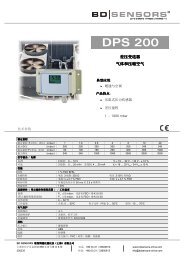
CIT 400 / CIT 401Display mode(measured value isdisplayed)PasswordactivationMenu PAoFParameters of thedisplayMenu diSPScaled measurementvaluesMenu diS1Input signalin mAMenu diS2Input signalin %Menu diS3Output signalin %Menu diS4Scaled valuewith offset anddisplay offsetMenu diS5Output signalin mAMenu diS6Parameters ofsignal inputMenu SinPStarting point ofmeasuring rangeMenu ZPinEnd point ofmeasuring rangeMenu EPinDecimal pointpositionMenu dPParameters forlinearizationMenu LinLinearizationon / offMenu Lin on/ offNumber ofsupporting pointMenu nSupporting pointinput signalMenu in nSupporting pointoutput signalMenu ou nNumber of supporting point: n = 2 ... 32"n" stands for the number of the supporting pointSwitching modehysteresis/compareMenu HY1/CP1Switching pointrelay 1Menu S1onReset pointrelay 1Menu S1ofContact invertingrelay 1Menu In1Switch-on delayrelay 1Menu D1onSwitch-off delayrelay 1Menu D1ofParameters ofcontactsMenu rELn1up to4Switching modehysteresis/compareMenu HY2/CP2Switching modehysteresis/compareMenu HY3/CP3Switching pointrelay 2Menu S2onSwitching pointrelay 3Menu S3onReset pointrelay 2Menu S2ofReset pointrelay 3Menu S3ofContact invertingrelay 2Menu In2Contact invertingrelay 3Menu In3Switch-on delayrelay 2Menu D2onSwitch-on delayrelay 3Menu D3onSwitch-off delayrelay 2Menu D2ofSwitch-off delayrelay 3Menu D3ofSwitching modehysteresis/compareMenu HY4/CP4Switching pointrelay 4Menu S4onReset pointrelay 4Menu S4ofContact invertingrelay 4Menu In4Switch-on delayrelay 4Menu D4onSwitch-off delayrelay 4Menu D4ofParameters ofanalogue outputMenu AoutOutputsignalMenu outYmin. measuredvalueMenu ZPoumax. measuredvalueMenu EPouSimulation/testing modeMenu tEStStatusrelay 1Menu R1SiStatusrelay 2Menu R2SiStatusrelay 3Menu R3SiStatusrelay 4Menu R4SiStatusalarm relayMenu ALSiStatusanalogue outputMenu AnSiOnOnOnOnOn0 mAOFFOFFOFFOFFOFF4 mA20 mAUnitparametersMenu ALLGRelaisexchangeMenu CHAnPasswordsettingMenu PAnrDefaultsettingMenu LoADfreely selectable (Si)OFF234Parameters forcalibrationMenu CALAdjusting signalinput of offsetMenu SioFAdjusting signalinput of spanMenu SiSPFig. 11 Menu system P07410
5.5 Menu listMenu level diSP - parameter of the display (mode)The menus "dIS1" to "dIS6" determine the display mode.CIT 400 / CIT 401Display - scaled measurement valuedIS1Indicates the scaled measurement value on the display. The indicatedvalue may vary between 0.000 and 9999. Confirm with Enter after selecting"dIS1" in order to activate this mode.Display - input in mAdIS2Indicates the input signal in mA on the display. In this mode, the unit virtuallyoperates as a mA-meter which indicates the sensor current. Confirmwith Enter after selecting "dIS2" in order to activate this displaymode.Display - input in %dIS3Indicates the input signal as percentage on the display. The value rangesbetween 0 and 100 % and has a direct relation to the sensor signalwhich varies within a range of 4 to 20 mA. Confirm withEnter after selecting "dlS3" in order to activate this display mode.Display - analogue output in %dIS4Indicates the output signal as percentage on the display. The valueranges between 0 and 100 % and has a direct relation to the analogueoutput of the transmitter which varies within a range of 4 to 20 mA (dependingon the value selected in menu "outY"). Confirm with Enter afterselecting "dlS4" in order to activate this display mode.Display - scaled measurement value with offset and display offsetdIS5Indicates the scaled measurement value with the added offset on thedisplay. The indicated value may vary between 0.000 and 9999. The displayoffset must be entered in the menu "dIS5". Confirm with Enter afterselecting "dlS5" in order to activate this display mode. The value set herewill be used as display offset and will be added to the investigated measurementvalue. Use the arrow keys to enter the numeric value and confirmwith Enter.Display - output in mAdIS6Indicates the output signal in mA on the display. In this mode, the unitvirtually operates as a mA-meter which represents the analogue outputof the transmitter. This is essential for the user to check the signal circuitto operate correctly and if subsequent evaluation units indicate the samevalues. Confirm with Enter after selecting "dlS6" in order to activate thisdisplay mode.11 www.bdsensors.com
CIT 400 / CIT 401Menu level SinP - parameter of signal input (analogue input)The subordinate menu items are used to define the measurement span of the analogue inputfor 4 mA and 20 mA.Signal input - starting point of measuring rangeZPInThe measurement value for the analogue input at 4 mA must be enteredhere. Normally this value is 0, which means 0 m at 4 mA in case of apressure probe with a measurement range of 0 to 6 m water columnheight. Use the arrow keys to enter the numeric value and confirm withEnter.Signal input - end point of measuring rangeEPInThe measurement value for the analogue input at 20 mA must be enteredhere. Normally this is the maximum measurement span, resultingfrom the example above, i. e. a value of 6. Use the arrow keys to enterthe numeric value and confirm with Enter.Signal input - decimal point positiondPHere you can define the decimal point position. Use the arrow keys tomove the decimal point and confirm with Enter.Menu level Lin - parameter of the linearizationVia this menu level, you can linearize the input signal (sensor) by a supporting point. This functionis essential when the sensor signal is not linear to the output signal of the process transmitter.By this function, it is possible to get an output signal nearly linear to the filling volume in irregularshaped tanks.Linearization - activation / deactivationLion/Liof With this menu, the linearization can be switched on or off. In the switchoffmode, the supporting points are not taken into account.Linearization - number of supporting pointsnIn this menu, the number of supporting points has to be set. The permissiblerange is set from 2 to 32 supporting points.Linearization - input signal of supporting pointsin nIn this menu, the first part of the supporting points has to be defined,whereas "n" in the menu designation is replaced by the number of thesupporting point (in 1, in 2, ... in32). The sensor signal of the respectivesupporting point which lies on the input must be entered. In the followingmenu, the corresponding output signal must be set. The input value isbased on the scaling limits defined in the menu level SinP.Linearization - output signal of the supporting pointsou nIn this menu, the second part of the supporting points has to be defined,whereas "n" in the menu designation is replaced by the value of the respectivesupporting point (ou 1, ou 2, ... ou32). The value has to be enteredcorresponding to the value for reaching a supporting point. Betweentwo supporting points, the course is linear. Please note that thesupporting points must be entered in ascending sequence, i. e. the valuefor n+1 has to be higher than the value for n. The output signal on theanalogue output is developed by the indicated value, whereas the parametersfrom the menu level Aout are used.12
Menu level rELn - parameter of the contacts (relais)CIT 400 / CIT 401The menu items of this level are responsible for the limit value settings and the switching behaviourof the relays. Since the menus for the relays have been conceived identically, the descriptionis the same for all menus. This menu level can be called up by pressing Enter like any othermenu. After that, the respective relay must be selected. This can be achieved by selecting thenumbers of the relay with the arrow keys. Confirm your selection with Enter (CIT 400 features 2relays; CIT 401 features 4 relays).Contacts - switching mode hysteresis/compareHY 1 / CP 1HY 2 / CP 2HY 3 / CP 3HY 4 / CP 4Contacts - switching pointS1onS2onS3onS4onContacts - reset pointS1ofS2ofS3ofS4ofContacts - invertingIn 1In 2In 3In 4Contacts - switch-on delayD1on D2onD3on D4onContacts - switch-off delayD1of D2ofD3of D4ofWith this menu, you can define the switching logic of the relays. It is possibleto select between the so-called hysteresis mode HY X (limit level)and the compare mode CP X (in bounds/out of bounds). Select with arrowkeys as usual – HYon indicates the selected hysteresis mode (limitlevel). CPon will indicate the window mode (in bounds/out of bounds).Confirm with Enter. (compare 7. Programming examples)This menu defines the upper switching point of the respective relay. Theprogramming example shows the function of this menu. In hysteresismode (limit level), this value determines e. g. the turn-on point. In windowmode (in bounds/out of bounds), this value determines e. g. the inbounds upper switching point. The value can be set using the arrow keys.Confirm with Enter.This menu defines the lower switching point of the respective relay. Theprogramming example shows the function of this menu. In hysteresismode (limit level), this value determines e. g. the reset point. In comparemode (in bounds/out of bounds), this value determines e. g. the inbounds lower switching point. The value can be set using the arrow keys.Confirm with Enter.This menu allows you to invert the relay position. In hysteresis mode(limit level), the upper and lower switching points will be changed. Inwindow mode (in bounds/out of bounds), the switching behaviour willchange from in bounds to out of bounds. Please note that this determinationis valid only in case of activated auxiliary power, as the relay has tobe powered with auxiliary power depending on the parameter setting.Relay inversion will be set by using the arrow keys. "St" in the displayindicates the standard position, "In" the inverted relay position. Confirmthe setting with Enter.This menu is used to define a switch-on delay within a range from 0 to100 seconds for the selected relay. Set the delay with the arrow keysand confirm with Enter.With this menu, you can define a switch-off delay within a range from 0to 100 seconds for the selected relay. Set the delay with the arrow keysand confirm with Enter.13 www.bdsensors.com
CIT 400 / CIT 401Menu level Aout - analogue outputThe settings for the analogue signal output are determined in the menu items.Analogausgang - output signaloutYThis menu defines the output signal range. You can choose betweenthe following settings: 4-20 mA, 0-20 mA, 20-4 mA and 20-0 mA. Selectby using the arrow keys and confirm with Enter.Analogue output - minimum measurement valueZPouIn this menu, you can enter the minimum measurement value whichshould correspond to the analogue output signal, e. g. 0 meters. If thesensor reaches this value, the output will be e. g. 4 mA if the signalrange in menu "outY" was set to 4-20 mA.Analogue output - maximum measurement valueEPouEnter the maximum measurement value which has to correspond tothe analogue output signal here. If, for example, "ZPIn" and "EPIn" of apressure sensor are given with 0 up to 6 meters, the menu "EPou" canbe set on 5 meters. If the sensor reaches this value, the output will bee. g. 20 mA if the signal range in menu "outY" was set to 4-20 mA.Menu level tESt - simulation / testing modeIn this menu level, all test and simulation menus are located. The simulation options cover amanual relay control as well as an analogue output signal simulation.Simulation - status of the relaysR1SIR2SIR3SIR4SIALSIThis menu is used to simulate the relay conditions. Menu "ALSI" is responsiblefor the alarm relay. By using the arrow keys, it is possible tosimulate the "energized" (ON) and "de-energized" (OFF) condition. Therelay will change its condition immediately after selection. Pressing Enterwill exit the respective simulation menu.Simulation - status of the analogue outputAnSIThe signal value of the analogue output can be simulated using thismenu. You can pre-set the fixed values 0 mA, 4 mA, 20 mA and variablevalues. In order to set a variable signal value, use the arrow keysto move to screen "SI" meaning output value simulation. Press Enterand "12.00" mA will appear as simulation value. Now you can set withthe arrow keys the signal value to be rendered on the signal output afterpressing the Enter key. Abort simulation by leaving this menu.14
Menu level ALLG - unit parameterMenu level contains general unit parameters.CIT 400 / CIT 401Unit parameter - relay exchangeCHAnWith this menu, you can set the exchange of used relays if they reach adefined value. The background of this function is a pump exchange inorder to achieve a regular pump load (capacity utilisation).By changing the relays, both pumps will be activated on reaching thenext turn-on point. With CIT 400, this function can be switched on andoff. With CIT 401, values 2, 3, 4, and OFF can be set. The value givesthe number of used relays for the changing.Unit parameter - password settingPAnrThis menu defines the unit password (PIN). Set the number by using thearrow keys and confirm with Enter. To activate the password, use menu"PAoF".The default setting for the password is "5".Unit parameter - default settingLoAdThe unit’s factory default settings can be loaded by using this menu. Inorder to execute this function, you should know the password (PIN). Ifthis function is selected, the unit will wait for PIN entry. The function willnot be executed until a correct entry of the password. The default settingfor the password is "5".Please note that also the password is reset to default.Menu level CAL - calibrationThis level is for self-calibration of the analogue input to the lower and upper sensor signal(4/20 mA). You can choose between single and double point calibration.Calibration - adjusting signal input of offsetSIofWith this menu, you can adjust the zero point of the transmitter(4 mA) to the applied sensor signal. To start the calibration, it is necessaryto enter the password. For this, the minimum output signal (outputof the min. measurement span of the sensor) must be applied to thetransmitter input.Calibration - adjusting signal input of spanSISPWith this menu, you can adjust the final value of the measurement span(20 mA) to the applied sensor signal. To start the calibration, it is necessaryto enter the password. For this, the maximum output signal (outputof the max. measurement span of the sensor) must be applied tothe transmitter input.15 www.bdsensors.com
CIT 400 / CIT 4016. Error handlingError messages Possible causeErr- cable break between sensor onanalogue input- mechanical sensor damage and thereforeinterruption- sensor damage-> current on analogue input below 3.3 mAErr- sensor electronics damaged- supplying too high current- cable short circuit or connection boxcauses current higher than 22 mA onanalogue input due to humidity ordamaged terminal clamps.-> current on analogue input higher than3.3 mAHeavy fluctuationof mea-- contacting problems due to cable- cable damagedsurement values- connection box or similarextension- humidity in the cable- sensor damageError corrective- check cable for damage- exchange cable or sensor ifnecessary- check cable for damage- exchange cable or sensor ifnecessary- check all contacts andconnections- replace filter on cable end- check connection box forhumidity ingressIf you detect an error, please try to eliminate it by this table or send the device to our serviceaddress for repair.Repairs on the device may only be performed by the manufacturer!7. Programming examplesPlease note that the display offset has to be set on "0" in the examples.Compare "dIS5" under "5.5 menu list".7.1 Level measurementgiven: tank (max. level 7 m); medium: water; probe 4-20 mA; measuring range 10 mrequired: indication of measurement value, pen recorder on analogue output (4-20 mA),final peak of pen recorder 20 mA at 7 mThe process transmitter has to indicate the max. filling level of the tank (7 m).measuring range0 up to 10 m16
Programming:Select the menu "dlS1" in the menu level "dlSP".Set the following values in the menu level "SInP":ZPIn = 0 (starting point of measuring range)EPIn = 10 (end point of pressure range)dP = 2 (decimal point position)Set the following values in the menu level "Aout":outY = 4-20 (output signal in mA)ZPou = 0 (min. measured value)EPou = 7 (max. measured value)7.2 Interface level measurementCIT 400 / CIT 401given: tank (max. level 7 m); medium: water, probe 4-20 mA, measurement range 10 mrequired: pen recorder on analogue output 4-20 mA, final peak of pen recorder 20 mA at 7 m;the process transmitter has to indicate the max. filling level of the tank; relay 1 shouldhave the function of a limit value switch (on = 6 m; off = 5 m)Please note that the values in "S1on" and "S2on" usually have to be higher than thevalues in "S1of" and "S2of". To exchange the switching points, please use the menucontact inverting ("In 1" and "In 2")ONS1on / S2onOFFS1of / S2ofOFFONONOFFswitch-on point > switch-off pointOFFS1on / S2onONS1of / S2ofONswitch-on point < switch-off pointProgrammingSelect the menu "dlS1" in the menu level "dlSP".Set the following values in the menu level "SinP":ZPIn = 0 (starting point of measuring range)EPIn = 10 (end point of pressure range)dP = 2 (decimal point position)Select the menu "1" in the menu level "rELn" and set the following values:HY 1/CP 1 = HYon (hysteresis mode)S1on = 6 (switching point relay 1)S1of = 5 (reset point relay 1)In1 = St (Set point inverting relay 1)Set the following values in the menu level "Aout":outY = 4-20 (output signal in mA)ZPou = 0 (min. measured value)EPou = 7 (max. measured value)OFFOFFON17 www.bdsensors.com
CIT 400 / CIT 4017.3 In bounds / out of boundsgiven:tank (max. level 7 m); medium: water; probe 4-20 mA; measuring range 10 mrequired: pen recorder on analogue output 4-20 mA, final peak of pen recorder 20 mA at 7 m;the process transmitter has to indicate the max. filling level of the tank, relay 1 shouldhave the function of an out of bounds switch and relay 2 the function of an in boundsswitch (bound between 3 m and 4 m)For using the out of bounds function, the menu "In 1" has to be set on "In".Please note that the values in "S1on" and "S2on" usually have to be higher than thevalues in "S1of" and "S2of". To exchange the switching points, please use the menucontact inverting ("In 1" and "In 2")OFFS1on / S2onONS1of / S2ofOFFin bounds functionONS1on / S2onOFFS1of / S2ofONout of bounds functionProgrammingSelect the menu "dlS1" in the menu level "dlSP".Set the following values in the menu level "SinP":ZPIn = 0 (starting point of measuring range)EPIn = 10 (end point of pressure range)dP = 2 (decimal point position)Select the menu "1" in the menu level "rELn" and set the following values:HY 1/CP 1 = CPon (window mode)S1on = 4 (switching point relay 1)S1of = 3 (reset point relay 1)In1 = In (set point inverting relay 1)Select the menu "2" in the menu level "rELn" and set the following values:HY 2/CP 2 = CPon (windows mode)S2on = 4 (switching point relay 2)S2of = 3 (reset point relay 2)In2 = St (no inverting of relay 2)Set the following values in the menu level "Aout":outY = 4-20 (output signal in mA)ZPou = 0 (min. measured value)EPou = 7 (max. measured value)18
7.4 Changing of pumpsCIT 400 / CIT 401given: tank (max. level 7 m); medium: water; probe 4-20 mA; measuring range 10 mrequired: pen recorder on analog output 4-20 mA, final peak of pen recorder 20 mA at 7 m;the process transmitter has to indicate the max. filling level of the tank (7 m); relay 1should have the function of a limit value switch (on = 6 m; off = 5 m) with a switch-ondelay of 10 seconds; alternating with relay 2 (on = 6 m; off = 4.5 m)Please note that the values in "S1on" and "S2on" usually have to be higher than thevalues in "S1of" and "S2of". To exchange the switching points, please use the menucontact inverting ("In 1" and "In 2")ProgrammingSelect the menu "dlS1" in the menu level "dlSP".Set the following values in the menu level "SinP":ZPIn = 0 (starting point of measuring range)EPIn = 10 (end point of pressure range)dP = 2 (decimal point position)Select the menu "1" in the menu level "rELn" and set the following values:HY 1/CP 1 = HYon (hysteresis mode)S1on = 6 (upper switching point 1)S1of = 5 (lower switching point 1)In1 = In (inverting of relay 1)d1on = 10 (switch-on delay in seconds)Select the menu "2" in the menu level "rELn" and set the following values:HY 2/CP 2 = HYon (hysteresis mode)S2on = 6 (upper switching point 2)S2of = 4.5 (lower switching point 2)In2 = In (inverting of relay 2)d2on = 10 (switch-on delay in seconds)Set the following values in the menu level "Aout":outY = 4-20 (output signal in mA)ZPou = 0 (min. measured value)EPou = 7 (max. measured value)Select the menu "ALLG" and set the following values:CHAn = On (change relays)8. Placing out of serviceWhen dismantling the device, this must always be done in the depressurized andcurrentless condition!9. ServiceThis device is maintenance-free.If desired, the device can be cleaned using non-aggressive cleaning solutions. Clean the housingwith a dry lint-free cloth if necessary. When cleaning the enclosure surface with a wet cloth,first disconnect the device from mains.19 www.bdsensors.com
CIT 400 / CIT 40110. RecalibrationDuring the life-time of the device, the offset may shift. As a consequence, a deviating signal valuein reference to the nominal pressure range starting point may be transmitted.The full scale may also shift. This would cause a signal value of the pressure switch to betransmitted that deviates from the nominal pressure range end point.If one of these two phenomena occurs after prolonged use, a recalibration is recommended toensure furthermore high accuracy.You can send us the device for recalibration. It is also possible to perform this recalibration byyourself with the help of a pressure reference. The required information is given in the menu"CAL" in the menu list.11. RepairIf there are malfunctions which cannot be eliminated the device should be sent to us for repair.Before that the device has to be cleaned carefully and packed shatter-proofed. Youhave to enclose a note of return with detailed defect description when sending the device. Ifyour device came in contact with harmful substances, a declaration of decontamination isadditionally required. Appropriate forms can be downloaded from our homepagewww.bdsensors.com. Should you dispatch a device without a declaration of decontaminationand if there are any doubts in our service department regarding the used medium, repairwill not be started until an acceptable declaration is sent.If the device came in contact with hazardous substances, certain precautionshave to be complied with for purification!Our service address:BD SENSORS GmbHServiceabteilungBD-Sensors-Str. 195199 ThiersteinGermany12. DisposalThe device must be disposed according to the European Directives 2002/96/ECand 2003/108/EC (on waste electrical and electronic equipment). Waste ofelectrical and electronic equipment may not be disposed by domestic refuse.Special consideration is required for the disposal if the device hasbeen in contact with hazardous substances!13. Warranty conditionsThe warranty conditions are subject to the legal warranty period of 24 months from the date ofdelivery. In case of improper use, modifications of or damages to the device, we do not acceptwarranty claims. Furthermore, defects due to normal wear are not subject to warranty services.20
CIT 400 / CIT 40114. Appendix14.1 Declaration of conformity21 www.bdsensors.com
CIT 400 / CIT 40114.2. EC type-examination for CIT 400 with Ex-protection22
CIT 400 / CIT 40123 www.bdsensors.com
CIT 400 / CIT 401BD SENSORS GmbHBD-Sensors-Str. 195199 ThiersteinGermanyPhone +49 (0) 92 35 / 98 11- 0Fax +49 (0) 92 35 / 98 11- 11The addresses of our 'Distribution Partners' are listed on our homepage www.bdsensors.com.It is possible to download data sheets, operating manuals, ordering codes and certificates,as well.further agencies in:EUROPEASIA• Belgium • Iran• Denmark • Israel• Germany • Kazakhstan• England • Taiwan• France • Thailand• Greece• Italy AUSTRALIA• Lithuania • Queensland• Luxembourg• Netherlands• Norway• Poland• Romania• Russia• Sweden• Switzerland• Slovakia• Spain• Czech Republic• Turkey• UkraineThe contents of this operating manual reflect the version available at the time of printing. Ithas been issued to our best knowledge and belief. However, errors may still be included. Forincorrect statements and their consequences, liability cannot be assumed by BD SENSORS.– Technical modifications reserved –Telefon +49 (0) 92 35 / 98 11- 0Telefax +49 (0) 92 35 / 98 11- 11www.bdsensors.deinfo@bdsensors.deCIT400-401_E_16071024