13 Deflections of beams - Free
13 Deflections of beams - Free
13 Deflections of beams - Free

Create successful ePaper yourself
Turn your PDF publications into a flip-book with our unique Google optimized e-Paper software.
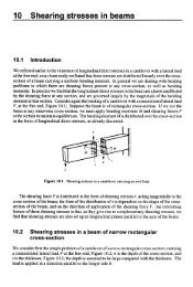
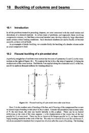
<strong>13</strong> <strong>Deflections</strong> <strong>of</strong> <strong>beams</strong><strong>13</strong>.1 IntroductionIn Chapter 7 we showed that the loading actions at any section <strong>of</strong> a simply-supported beam orcantilever can be resolved into a bending moment and a shearing force. Subsequently, inChapters9 and 10, we discussed ways <strong>of</strong> estimating the stresses due to these bending moments and shearingforces. There is, however, another aspect <strong>of</strong> the problem <strong>of</strong> bending which remains to be treated,namely, the calculation <strong>of</strong> the stifiess <strong>of</strong> a beam. In most practical cases, it is necessary that abeam should be not only strong enough for its purpose, but also that it should have the requisitestiffness, that is, it should not deflect from its original position by more than a certain amount.Again, there are certain types <strong>of</strong><strong>beams</strong>, such as those camed by more than two supports and <strong>beams</strong>with their ends held in such a way that they must keep their original directions, for which wecannot calculate bending moments and shearing forces without studying the deformations <strong>of</strong> theaxis <strong>of</strong> the beam; these problems are statically indeterminate, in fact.In this chapter we consider methods <strong>of</strong> finding the deflected form <strong>of</strong> a beam under a givensystem <strong>of</strong> external loads and having known conditions <strong>of</strong> support.<strong>13</strong>.2 Elastic bending <strong>of</strong> straight <strong>beams</strong>It was shown in Section 9.2 that a straight beam <strong>of</strong> uniform cross-section, when subjected to endcouples A4 applied about a principal axis, bends into a circular arc <strong>of</strong> radius R, given by---1 M- (<strong>13</strong>.1)R EIwhere EI, which is the product <strong>of</strong> Young's modulus E and the second moment <strong>of</strong> area I about therelevant principal axis, is the flexural stiffness <strong>of</strong> the beam; equation ( <strong>13</strong>.1) holds only for elasticbending.Where a beam is subjected to shearing forces, as well as bending moments, the axis <strong>of</strong> the beamis no longer bent to a circular arc. To deal with this type <strong>of</strong> problem, we assume that equation(<strong>13</strong>.1) still defines the radius <strong>of</strong> curvature at any point <strong>of</strong> the beam where the bending moment isM. This implies that where the bending moment varies from one section <strong>of</strong> the beam to another,the radius <strong>of</strong> curvature also vanes from section to section, in accordance with equation (<strong>13</strong>.1).In the unstrained condition <strong>of</strong> the beam, Cz is the longitudinal centroidal axis, Figure <strong>13</strong>.1, andCx, Cy are the principal axes in the cross-section. The co-ordinate axes Cx, Cy are so arranged thatthe y-axis is vertically downwards. This is convenient as most practical loading conditions giverise to vertically downwards deflections. Suppose bending moments are applied about axesparallel to Cx, so that bending is restricted to the yz-plane, because Cx and Cy are principal axes.
298 <strong>Deflections</strong> <strong>of</strong> <strong>beams</strong>where A is a constant. On integrating once more1EIv = -- Mz’ + AI + B2(<strong>13</strong>.9)where B is another constant. If we measure v relative to a line CD joining the ends <strong>of</strong> the beam,vis zero at each end. Then v = 0, for z = 0 and z = L.On substituting these two conditions into equation (<strong>13</strong>.9), we have1B = 0 and A = -ML2The equation (<strong>13</strong>.9) may be written1EIv = -Mz(L - Z)2(<strong>13</strong>.10)At the mid-length, z = U., andv = ML 2-8EI(<strong>13</strong>.11)which is the greatest deflection. At the ends z = 0 and z = L/2,d v - ML dv ML- -(iz 2 EI a!? 2 EI- at C; - = -- at D(<strong>13</strong>.12)It is important to appreciate that equation (<strong>13</strong>.3), expressing the radius <strong>of</strong> curvature R in terms <strong>of</strong>v, is only true if the displacement v is small.Figure <strong>13</strong>.5 Distortion <strong>of</strong> a beam in pure bending.
Elastic bending <strong>of</strong> straight <strong>beams</strong> 299We can study more accurately the pure bending <strong>of</strong> a beam by considering it to be deformed intothe arc <strong>of</strong> a circle, Figure <strong>13</strong>.5; as the bending moment M is constant at all sections <strong>of</strong> the beam,the radius <strong>of</strong> curvature R is the same for all sections. If L is the length between the ends, Figure<strong>13</strong>.5, and D is the mid-point,OB = 4-jThus the central deflection v, isv = BD = R - \IR2 - (L2/4)Thenv = i iSuppose WR is considerably less than unity; thenwhich can be written1L2 L2I+-+ ...8R 4Rv = -1Butand so-il+- v = ML M8EI 4(E42+...I ~ L ~(<strong>13</strong>.<strong>13</strong>)Clearly, if (L2/4Rz) is negligible compared with unity we have, approximately,which agrees with equation (1 3.1 1). The more accurate equation (<strong>13</strong>.<strong>13</strong>) shows that, when (Lz/4R2)
300 <strong>Deflections</strong> <strong>of</strong> <strong>beams</strong>is not negligible, the relationshp between v and A4 is non-linear; for all practical purposes thisrefinement is unimportant, and we find simple linear relationships <strong>of</strong> the type <strong>of</strong> equation (1 3.1 1)are sufficiently accurate for engineering purposes.<strong>13</strong>.3 Simply-supported beam carrying a uniformly distributed loadA beam <strong>of</strong> uniform flexural stiffness EI and span L is simply-supported at its ends, Figure <strong>13</strong>.6;it carries a uniformly distributed lateral load <strong>of</strong> w per unit length, whch induces bending in the yzplane only. Then the reactions at the ends are each equal to %wL; if z is measured from the endC, the bending moment at a distance z from C is1 1 2M = -WLZ - -WZ2 2Figure <strong>13</strong>.6 Simply-supported beam carrying a uniformly supported load.Then from equation ( <strong>13</strong> S),Eld2v1 1= -M = -- WLZ + - wz2dz2 2 2On integrating,dv WLZ 2 wz 3EI- = --+dz4 6+ AandEIv = --wLz3 + -wz4+Az+B (<strong>13</strong>.14)12 24Suppose v = 0 at the ends z = 0 and z = L; thenB = 0, and A = wL’I24
Cantilever with a concentrated load 301Then equation (<strong>13</strong>.14) becomeswzEZv = - [L’ - 2Lz2 + z’]24(<strong>13</strong>.15)The deflection at the mid-length, z = Y., is5wL4v = -3 84 El(1 3.16)<strong>13</strong>.4 Cantilever with a concentrated loadA uniform cantilever <strong>of</strong> flexural stiffness Eland length L carries a vertical concentrated load Watthe free end, Figure <strong>13</strong>.7. The bending moment a distance z from the built-in end isM = -W(L - z)Figure <strong>13</strong>.7 Cantilever carrying a vertical load at the remote end.Hence equation ( <strong>13</strong>.5) givesd2vEZ- = W(L - Z)dz2ThenEIk = w(Lz - i Z 2 ) -L A (<strong>13</strong>.17)dzand
302 <strong>Deflections</strong> <strong>of</strong> <strong>beams</strong>EIv = W( ;Lz2 - iz3) + Az + BAt the end z = 0, there is zero slope in the deflected form, so that dv/dz = 0; then equation(<strong>13</strong>.17) gives A = 0. Furthermore, at z = 0 there is also no deflection, so that B = 0. Thenwz 2EIv = - (3L - Z)6Atthe free end,^ = L,WL 3VI. = -3 EI(<strong>13</strong>.18)The slope <strong>of</strong> the beam at the free end is0, = (2)- - WL2? = L 2EI(<strong>13</strong>.19)When the cantilever is loaded at some point between the ends, at a distance a, say, from thebuilt-in support, Figure <strong>13</strong>.8, the beam between G and D carries no bending moments and thereforeremains straight. The deflection at G can be deduced from equation (<strong>13</strong>.18); for z = a,wa 3v, = -3 E/(<strong>13</strong>.20)and the slope at z = a isWa 2eo = -2EI(<strong>13</strong>.21)Then the deflection at the free end D <strong>of</strong> the cantilever isFigure <strong>13</strong>.8 Cantilever with a load applied between the ends.
Cantilever with a uniformly distributed load 303Wa ’VL = - wu3 + (L - a) -3EI2EI-- wu2 ( 3 - ~ a)6EI(<strong>13</strong>.22)<strong>13</strong>.5 Cantilever with a uniformly distributed loadA uniform cantilever, Figure <strong>13</strong>.9, carries a uniformly distributed load <strong>of</strong> w per unit length overthe whole <strong>of</strong> its length. The bending moment at a distance z from C is1M = --w (L - z)’2Then, from equation (<strong>13</strong>.5),d‘v 1 1EI- = -W (L - z)’ = -W (L2 - ~ L + z z’)dz’ 2 2Figure <strong>13</strong>.9 Cantilever carrying a uniformly distributed load.ThusandEI- = -w L’z - Lz2 + -z3 + A* 7 7dz 2 3’ 1I’EIv1= -w -L’z’ - -Lz3 + -z4 + Az + B21 2 3 12At the built end, z = 0, and we have
304 <strong>Deflections</strong> <strong>of</strong> <strong>beams</strong>-& - O and v = OCLThusA = B = 0. Then1E~v = -W (6L2z2- 4Lz3 + z4)24At the free end, D, the vertical deflection isWL 4VL = -8EI(<strong>13</strong>.23)<strong>13</strong>.6 Propped cantilever with distributed loadThe uniform cantilever <strong>of</strong> Figure <strong>13</strong>.1 O(i) carries a uniformly distributed load w and is supportedon a rigid knife edge at the end D. Suppose P is the force on the support at D. Then we regardFigure <strong>13</strong>.10(i) as the superposition <strong>of</strong> the effects <strong>of</strong> P and w acting separately.Figure <strong>13</strong>.10 (i) Uniformly loaded cantilever propped at one end.(ii) <strong>Deflections</strong> due to w alone. (iii) <strong>Deflections</strong> due to P alone.If w acts alone, the deflection at D is given by equation (<strong>13</strong>.23), and has the valueWL 4v, = -8EIIf the reaction P acted alone, there would be an upward deflectionPL 3v* = -3 EI
at D. If the support maintains zero deflection at D,v,-v2 = 0Propped cantilever with distributed load 305Thls gives-PL3- -- WL3EI 8EIorp = - 3wL8(<strong>13</strong>.24)Problem <strong>13</strong>.1A steel rod 5 cm diameter protrudes 2 m horizontally from a wall. (i)Calculate the deflection due to a load <strong>of</strong> 1 kN hung on the end <strong>of</strong> the rod. Theweight <strong>of</strong> the rod may be neglected. (ii) If a vertical steel wire 3 m long, 0.25cm diameter, supports the end <strong>of</strong> the cantilever, being taut but unstressedbefore the load is applied, calculate the end deflection on application <strong>of</strong> theload. TakeE = 200GN/m2. (RNEC)Solution(1) The second moment <strong>of</strong> are <strong>of</strong> the cross-section isTI, = - (0.050)4 = 0.307 x m464The deflection at the end is then(ii)Let T = tension in the wire; the area <strong>of</strong> cross-section <strong>of</strong> the wire is 4.90 xelongation <strong>of</strong>the wire is thene = - -EA- T(3)(200 x 109)(4.90 xm2. TheThe load on the end <strong>of</strong> the cantilever is then (1000 - T), and this produces a deflection <strong>of</strong>(1000 - fi(2)3v =3(200 x 109)(0.307 x
306 <strong>Deflections</strong> <strong>of</strong> <strong>beams</strong>If this equals the stretching <strong>of</strong> the wire, then(1000- 71(2)3 - T(3)3(200 x 109)(0.307 x 1O-6) (200 x 109)(4.90 x 1O-6)This gives T = 934 N, and the deflection <strong>of</strong> the cantilever becomesv = (66)(2)3 = 0.00276 m3(200 x 109)(0.307 x 1O-6)Problem <strong>13</strong>.2A platform carrying a uniformly distributed load rests on two cantileversprojecting a distance 1 m from a wall. The distance between the two cantileversis %1. In what ratio might the load on the platform be increased if the endswere supported by a cross girder <strong>of</strong> the same section as the cantilevers, restingon a rigid column in the centre, as shown? It may be assumed that when thereis no load on the platform the cantilevers just touch the cross girder withoutpressure. (Cambridge)SolutionLet w, = the safe load per unit length on each cantilever when unsupported.Then the maximum bending moment = %w, 12.Let w, = the safe load when supported,6 = the deflection <strong>of</strong> the end <strong>of</strong> each cantilever,I/tR = the pressure between each cantilever and the cross girder.Then the pressure is3 3 E16-R -- - w,l --2 8 - I’
Simply-supported beam carrying a concentrated lateral load 307We see from the figure above that(R/2)(1/4)3 - R<strong>13</strong>3 EI 384 EIis= - -I having the same value for the cantilevers and cross girder. Substituting this value <strong>of</strong> 6- R -3w21 R---2 8 128or48R = -w2165The upward pressure on the end <strong>of</strong> each cantilever is YJ? = 24wJ/65, giving a bending momentat the wall equal to 24wJ2/65. The bending moment <strong>of</strong> opposite sign due to the distributed loadis %wJ2. Hence it is clear that the maximum bending moment due to both acting together mustoccur at the wall and is equal to (% - 24/65) wJ2 = (17/<strong>13</strong>0) wJ2. If h s is to be equal to % wIZ2,we must have w, = (65/17) w,; in other words, the load on the platform can be increased in theratio 65/17, or nearly 4/1. The bending moment at the centre <strong>of</strong> the cross girder is 6~~1’165, whichis less than that at the wall.<strong>13</strong>.7 Simply-supported beam carrying a concentrated lateral loadConsider a beam <strong>of</strong> uniform flexural stiffness EI and length L, which is simply-supported at itsends C and G, Figure <strong>13</strong>.1 1. The beam carries a concentrated lateral load W at a distance a fromC. Then the reactions at C and G areWav, = E (L - u) vc = -LLFigure <strong>13</strong>.11<strong>Deflections</strong> <strong>of</strong> a simply-supported beamcarrying a concentrated lateral load.Now consider a section <strong>of</strong> the beam a distance z from C; if z < a, the bending moment at thesection is
308<strong>Deflections</strong> <strong>of</strong> <strong>beams</strong>M = vczand ifz > a,M = V,Z- Mz - a)ThenEId2v= -V, z for z < adz2andE& = -vC z + ~ (- z a) for z > adz2On integrating these equations, we haveEIdv1= --Vc z2 + A for z < adz 2(<strong>13</strong>.25)dv 1EI- = --Vcz2 +W(iz2 -az) +A' for z > adz 2(<strong>13</strong>.26)and1EIv = --Vc z3 + AZ + B for z < a6(<strong>13</strong>.27)+A'z + B' for z>a (<strong>13</strong>.28)In these equations A, B, A' and B' are arbitrary constants. Now for z = a the values <strong>of</strong> v given byequations (<strong>13</strong>.27) and(<strong>13</strong>.28) are equal, and the slopes given by equations (<strong>13</strong>.25) and(<strong>13</strong>.26) arealso equal, as there is continuity <strong>of</strong> the deflected form <strong>of</strong> the beam through the point D. Then1 1--vc a3 + Aa + B = --Vc 6 a3 + W($-<strong>13</strong> - t .3) + Aia + Bi6and
Simply-supported beam carrying a concentrated lateral load 309These two equations give(<strong>13</strong>.29)Ai the extreme ends <strong>of</strong> the beam v = 0, so that when z = 0 equation (1 3.27) gives B = 0, and whenz =L, equation (<strong>13</strong>.28) givesWe have finally,1 WA = -V, L2 -- (L - a)’6 6LB = O(<strong>13</strong>.30)But Vc = W(L - a)/L, so that equations (<strong>13</strong>.30) becomeWaA = - (L - a)(2L - a)6LB = O(<strong>13</strong>.31)
310 <strong>Deflections</strong> <strong>of</strong> <strong>beams</strong>Then equations (<strong>13</strong>.27) and (<strong>13</strong>.28) may be writtenEIV=W6L6L~L’-~uL+u~ z forz a, may be writtenWEIv= --(L-a)z3+-6L6L(2L2 - 3aL+ u23(<strong>13</strong>.34)Then equations (<strong>13</strong>.32) and (<strong>13</strong>.33) differ only by the last term <strong>of</strong> equation (<strong>13</strong>.34); ifthe last term<strong>of</strong> equation (<strong>13</strong>.34) is discarded when z < a, then equation (<strong>13</strong>.34) may be used to define thedeflected form in all parts <strong>of</strong> the beam.On putting z = a, the deflection at the loaded point D isVD =wa2 (L - .)23 EIL(<strong>13</strong>.35)When W is at the centre <strong>of</strong> the beam, a = %L, andWLVD = -48EI(<strong>13</strong>.36)This is the maximum deflection <strong>of</strong> the beam only when a = %L.<strong>13</strong>.8 Macaulay’s methodThe observation that equations (<strong>13</strong>.32) and (<strong>13</strong>.33) differ only by the last term <strong>of</strong> equation (<strong>13</strong>.34)leads to Macaulay‘s method, which ignores terms which are negative withm the Macaulay brackets.That is, if the term [z -a] in equation (<strong>13</strong>.34) is negative, it is ignored, so that equation (<strong>13</strong>.34) canbe used for the whole beam. The method will be demonstrated by applying it to a few examples.Consider the beam shown in Figure <strong>13</strong>.12, which is simply-supported at its ends and loadedwith a concentrated load W.
Macaulay’s method 31 1Figure <strong>13</strong>.12 Form <strong>of</strong> step-function used in deflection analysis <strong>of</strong> a beam.By taking moments, it can be seen thatv, = w (L - a)/L (<strong>13</strong>.37)and the bending moment when z < a isM = vcz (<strong>13</strong>.38)Then bending moment when z > a isM = vc z - W(Z - a) (<strong>13</strong>.39)Nowd2vEl - = -Mdz2hence, the Macaulay method allows us to express this relationship as follows- - - - - - - z < = a -_--__-* ---__ -----a < z < Ld’vEI - =dz’-Vc z+w [z - a](<strong>13</strong>.40)On integrating equation (<strong>13</strong>.40), we getv, z2 WE/- dv1 -- + A +- [z - a]’dz 2 2(<strong>13</strong>.41)and-v z3 WEIV = C +A~+B ++-.I’6 6(<strong>13</strong>.42)
312 Deflection <strong>of</strong> barnsThe term on the right <strong>of</strong> equations ( <strong>13</strong>.40) and ( <strong>13</strong>.4 1) must be integrated by the manner shown,so that the arbitrary constants A and B apply when z < a and also when z > a. The square brackets[ ] are called Macaulay brackets and do not appi'y when the term inside them is negative.The two boundary conditions are:atz = 0, v = 0 and atz = L, v = 0Applying the first boundary condition to equation (<strong>13</strong>.42), we getB = OApplying the second boundary condition to equation (<strong>13</strong>.42), we get0 = -V, L3/6 + AL + W (L - ~ ) ~ / 6or AL = W (L - a) L3/(6L) - W (L - ~ )~/6or A = W (L - a) L/6 - W (L - u )~/(~L)- W (L - a) {L - (L - a)Z/L}6:. EIv = -W(L - a)z3/(6L)+ w(L - a) (4 - (L - u)~/L}x/~+ W[Z - aF/6On putting z = a, we get the deflection at D, namely v,i e.VD = (L - a) {-a3/L + (L - (L - a)2/L) a + 0)6EI= wL - a) {-a3/L + (L - (L2 - 2aL + a2)/L) a}6EI= NL - a) (-a3/L + La - La + 2a2 - a3/L)6EIor VD =HqL - a)? a23 EIL
Simply-supported beam with distributed load over a portion <strong>of</strong> the span 3<strong>13</strong>If W is placed centrally, so that a = W2,VD =w( L- L / 2)2 (L / 2)3 EIL(<strong>13</strong>.43)<strong>13</strong>.9 Simply-supported beam with distributed load over a portion <strong>of</strong>the spanSuppose that the load is w per unit length over the portion DG, Figure <strong>13</strong>.<strong>13</strong>; the reactions at theends <strong>of</strong> the beam areWvC = - (L - a)22LWvc = -(p- a2)2LThe bending moment at a &stance z from C iswhere the square brackets are Macaulay brackets, which only apply when the term inside them ispositive.M = -(L-a)2z-~[z-a]2Wi.e.2LHenced’v -wEI-=-(L-&2 2LU)‘ z(<strong>13</strong>.44)d v wso that EI-= -(L-a)’z2+A& 4Land-WEIv = -(L-a)’z3t12LAzt B+ “[.-.IZ 2+“[.-a]’6Wt -[z- .I424(<strong>13</strong>.45)(<strong>13</strong>.46)
314 Deflection <strong>of</strong> <strong>beams</strong>The boundary conditions are that whenFigure <strong>13</strong>.<strong>13</strong> Load extending to one support.z = 0, v = 0 andwhen z = L, v = 0Applying the first boundary condition to equation (<strong>13</strong>.46), we getB = OApplying the second boundary condition to equation ( 1 3.46), we geto =--(L-U) L~+AL+-(L-u)12 24W 2 W 4W 2 W 4:.A = -(L-U) L--(L-U)12 24 L= -"( L-a) 2{ 2L2-(k?)2}24 L= -(L-u)2(2L2-L2-u*W24 L+2uL1orA = -(L-u)2( W24 LL2+2Lu-u2)The equation for the deflection curve is then:EIv = -(L-a)2z3+-(L-a)-W W 2 (L2+ 2Lu-a2)z2L24 L+-[,-.I4 W24(<strong>13</strong>.47)where the square brackets in equation (<strong>13</strong>.47) are Macaulay brackets.When the load does not extend to either support, Figure <strong>13</strong>.14(i), the result <strong>of</strong> equation ( 1 3.47)may be used by superposing an upwards distributed load <strong>of</strong> w per unit length over the length GH
Simply-supported beam with distributed load over a portion <strong>of</strong> the span 315on a downwards distributed load <strong>of</strong> w per unit length over DH, Figure <strong>13</strong>.14(ii). Due to thedownwards distributed load aloneEIv =-(L-u) -W 2 z ~+-(L-u)~(L~+~Lu-u~Wz2L24 L+q-q24(<strong>13</strong>.48)where the square brackets in equation (<strong>13</strong>.48) are Macaulay brackets.1Figure <strong>13</strong>.14 Load not extending to either support.Due to the upwards distributed loadEZv = -(L-b)2z3--(L-b)2(L2+2L6-b2W W z2L24 L1--[z- W24bI4(<strong>13</strong>.49)where the square brackets in equation (1 3.49) are Macaulay brackets.On superposing the two deflected forms, the resultant deflection is given by3wzWEIv = - -(b-~) (2L-U- 6) + -2L24 L{(L-.)2 (f.2 + 2La -a’) -(L-b)2 ( L2 -b 2Lb 4 2 ) ) (<strong>13</strong>.50)+-+14 W24- --[z-~I~ W
316 Defleetion <strong>of</strong> <strong>beams</strong>where the square brackets <strong>of</strong> equation (<strong>13</strong>.50) are Macaulay brackets and must be ignored if theterm inside them becomes negative.<strong>13</strong>.10 Simply-supported beam with a couple applied at anintermediate pointThe simply-supported beam <strong>of</strong> Figure <strong>13</strong>.15 carries a couple M, applied to the beam at a point adistance u from C. The vertical reactions at each end are (MJL). The bending moment a distancez from C isM2M = - + Mu [z - u]"L(<strong>13</strong>.51)Figure <strong>13</strong>.15 Beam with a couple applied at a point in the span.The term on the right <strong>of</strong> equation (1 3.5 1) is so written, so that equation (1 3.5 1) applied over thewhole length <strong>of</strong> the beam.Hence,c -- - - - - - - - z < = u ---------- - cd'v MazEl-=dz2L------a < z < L ------- Ma [z- U]Odvdz... El - = -Maz2+A - Ma[Z-U] (<strong>13</strong>.52)2LandEIv = - Maz t Azt B6LThe boundary conditions are that3Ma- -[z- u]'2(<strong>13</strong>.53)v = 0 at z = O andat z = LFrom the first boundary condition, we getB = O
Simply-supported beam with a couple applied at an intermediate point 317From the second boundary condition, we getMk' -40 = - + AL - (L - a)'6 2-MkMa6 2L:. A = - + - (L - a)'==- Ma (-L' + 3L' + 30' - 6aL)6L- Ma (2L' - 6La + 3~')6L6L6L2L2-6La+3a 2) +- -";"-[,-a12(<strong>13</strong>.54)where the square brackets in equation (<strong>13</strong>.54) are Macaulay brackets.The deflection at D, when z = a, isMilaVD = - (L - a) (L - 2 43 EIL(<strong>13</strong>.55)Problem <strong>13</strong>.3A steel beam rests on two supports 6 m apart, and carries a uniformlydistributed load <strong>of</strong> 10 kN per metre run. The second moment <strong>of</strong> area <strong>of</strong> thecross-section is 1 x m4 and E = 200 GN/m2. Estimate the maximumdeflection.SolutionThe greatest deflection occurs at mid-length and has the value given by equation (1 3.16):5wL4 - 5(100 x 10)) (6)4y = - -384EI 384(200 x 10') (1 x lo-))= 0.00844 m
318 <strong>Deflections</strong> <strong>of</strong> <strong>beams</strong>Problem <strong>13</strong>.4A uniform, simply-supported beam <strong>of</strong> span L carries a uniformly distributedlateral load <strong>of</strong> w per unit length. It is propped on a knife-edge support at adistance a from one end. Estimate the vertical force on the prop.R = - WL81 - 2 [;)2 + [$E(, L - $
Simply-supported beam with a couple applied at an intermediate point 319SolutionFrom section <strong>13</strong>.7, the lateral deflection at any point is given byW6Lwa6LEIV = --(L - a)z3 + -b~* - ~ U L+ a*)z for z > aW wz = waEIv = --(L - a)z3 +-(z - 3a) +-(2L2 + a2)z --wa3 for z > a6L 6 6L 6Let us suppose first that a > %L, when we would expect the greatest deflection to occur in therange z < a; over this rangeThis is zero wheni.e. whenEI- m,= -- Wwa(L - a)z2 + - (2L' - 3aL + a*)dz 2L 6LW-- (L - a)z2 + 5 ( 2~3 - 3 a ~2L6L1(L - a)z2 = -a (2LZ - 3aL + a*)3+ a2) = oor whenz = 4-If this gives a root in the range z < a, thenG-- (2L - a) < aand 2L -a < 3a, or a > %L. This is compatible with our earlier suppositions. Then, with a > %L,the greatest deflection occurs at the point
320 <strong>Deflections</strong> <strong>of</strong> <strong>beams</strong>-1z = [(a/3) (2L - a)I2 and has the value4-wa (2L - a) (L - a)9LEIvmax = -If a < %L, the greatest deflection occurs in the range z > a; in this case we replace a by (L - a),whence the greatest deflection occurs at the pointz= ,/-,andhasthevalue=v, - 9LEI (L2 - q-3<strong>13</strong>.11 Beam with end couples and distributed loadSuppose the ends <strong>of</strong> the beam CD, Figure <strong>13</strong>.16, rest on knife-edges, and carry couples M, and MPIf, in addition, the beam carries a uniformly distributed lateral load w per unit length, the bendingmoment a distance z from C isMc z 1M = -(L-z)+M,-+-wz(L-z)L L 2The equation <strong>of</strong> the deflection curve is then given byd2v Mc z 1Ef - - -- (L - Z ) - MD - - - wz (L - Z)dZ2 L L 2ThenEI- *--- %(Lz - Tz2) 1dZ L- ?(:) MD- ?w($ 1 - $) + AFigure <strong>13</strong>.16 Simply-supported beam carrying a uniformly suuuorted load.
Beam with end couples and distributed load 321and(<strong>13</strong>.56)If the ends <strong>of</strong> the beam remain at the same level, v = 0 for z = 0 and z = L. Then B = 0 andThen+Z24+The slopes at the ends are= - L (84. + 4MD + wL2)( z)z=o 24EI= -- L (44 + 8MD + wL2)24EISuppose that the end D <strong>of</strong> the beam now slnks an amount 6 downwards relative to C. Then at v =Lwe have v = 6, instead <strong>of</strong> v = 0. In equation (<strong>13</strong>.56), A is then given by1 1 1AL = E16 + -M&’ + -Md2 + -wL43 6 24For the slopes at the ends we have(s)z=oL 624EIL= - (8M, + 4MD + wL2) + -- --L6(4Mc + 8M, + wL2) + -24EIL(<strong>13</strong>.57)
322 <strong>Deflections</strong> <strong>of</strong> <strong>beams</strong><strong>13</strong>.12 Beams with non-uniformly distributed loadWhen a beam carries a load which is not uniformly distributed the methods <strong>of</strong> the previous articlescan still be employed if M and JMdz are both integrable functions <strong>of</strong> z, for we have in all casesd2v-EI- =dz'M"(") =which can be written in the formd z d z-- MEIIf I is uniform along the beam the first integral <strong>of</strong> this ism,- = A-'[M& EI (<strong>13</strong>.58)G5where A is a constant. The second integral is1v = AZ + B -- [[Mdzdz (<strong>13</strong>.59)E/If M and JM dz are integrable function <strong>of</strong> z the process <strong>of</strong> finding v can be continued analytically,the constants A and B being found from the terminal conditions. Failing this the integrations mustbe performed graphically or numerically. This is most readily done by plotting the bendingmomentcurve, and from that deducing a curve <strong>of</strong> areas representing JM dz. From this curve athird is deduced representing JJM dz dz.Problem <strong>13</strong>.6A uniform, simply-supported beam carries a distributed lateral load varying inintensity from w, at one end to 2w0 at the other. Calculate the greatest lateraldeflection in the beam.SolutionThe vertical reactions at 0 and A are (2<strong>13</strong>) wJ and (516) wJ. The bending moment at any sectiona distance z from 0 is then
Beams with non-uniformly distributed load 323M2 1 WG3= -w,Lz - TWG~3 6L- -ThenOn integrating once,where C, is a constant.-ITOn integrating further,*w&3 W#4EIv = - --+24 120Lc,z + c2where C, is a further constant. If v = 0 at z = L, we have11C, = --w,,L3 and C, = 0180Then11 W,LZ~ wG4 wG5EIv = - w&’z - - - - + -180 9 24 120LThe greatest deflection occurs at dv/dz = 0, i.e. when-W,LZ* WG3 W#4 -11 w*L3--+-+- -180 3 6 24Lor when+ 60(;)3 - 120(;)2 + 22 =The relevant root <strong>of</strong> this equation is z/L =OS06 which gives the point <strong>of</strong> maximum deflection neaito the mid-length. The maximum deflection is
324 <strong>Deflections</strong> <strong>of</strong> <strong>beams</strong>7.03 w, L4 wo L4v, i --- - 0.0195-360 EI EIThis is negligibly different from the deflection at mid-span, which is5w0L4(VIz = L/2 = -256EI<strong>13</strong>.<strong>13</strong> Cantilever with irregular loadingIn Figure <strong>13</strong>.17(i) a cantilever is free at D and built-in to a rigid wall at C. The bending momentcurve is DM <strong>of</strong> Figure <strong>13</strong>.17(ii); the bending moments are assumed to be hogging, and aretherefore negative. The curve CH represents JtM dz, and its ordinates are drawn downwardsbecause M is negative. The curve CG is then constructed from CH by finding1 [Mi&&Inequation(l3.51),theconstantsAandBarebothzeroas v = Oanddvldz = Oatz = 0. ThenCD is the base line for both curves.Figure <strong>13</strong>.17 Cantilever carrying any system <strong>of</strong> lateral loads.<strong>13</strong>.14 Beams <strong>of</strong> varying sectionWhen the second moment <strong>of</strong> area <strong>of</strong> a beam varies from one section to another, equations (1 3.58)and (<strong>13</strong>.59) take the forms- -dzdV - A - L J ?E
Cantilever with irregular loading 325andv = Az+B-- 1 r,+EThe general method <strong>of</strong> procedure follows the same lines as before. If (M/I) and J(M/l)dz areintegrable functions <strong>of</strong> z, then (dv/dz) and v may be evaluated analytically; otherwise graphical ornumerical methods must be employed, when a curve <strong>of</strong> (M/I) must be taken as the starting pointinstead <strong>of</strong> a curve <strong>of</strong> M.Problem <strong>13</strong>.7A cantilever strip has a length L, a constant breadth b and thickness t varyingin such a way that when the cantilever carries a lateral end load W, the centreline <strong>of</strong> the strip is bent into a circular arc. Find the form <strong>of</strong> variation <strong>of</strong> thethckness t.SolutionThe second moment <strong>of</strong> area, I, at any section is1I = -bt312The bending moment at any section is (- Wz), so thatd2vEl- = WZdz2Then-d2v - -wzrL2 ElIf the cantilever is bent into a circular arc, then d*v/dZ' is constant, and we must havewz-- - constantEI
326 <strong>Deflections</strong> <strong>of</strong> <strong>beams</strong>This requires thatZ--I- constantor I " 2Thus,1- bt' ot z12or1t " z3Any variation <strong>of</strong> the formt = to ($71where to is the thickness at the built-in end will lead to bending in the form <strong>of</strong> a circular arc.Problem <strong>13</strong>.8The curve M, below, represents the bending moment at any section <strong>of</strong> a timbercantilever <strong>of</strong> variable bending stiffness. The second moments <strong>of</strong> area are givenin the table below. Taking E = 11 GN/m2, deduce the deflection curve.z(frornsupportedend)(rn) 0 0.1 0.2 0.3 0.5 0.7 0.9 1.1 1.3 1.5 1.6 1.7I (m') 50.8 27.4 17.4 12.25 5.65 3.23 1.69 0.783 0.278 0.074 0.0298 0 x10~4
Non-uniformly distributed load and terminal couples 321SolutionThe first step is to calculate M/I at each section and to plot the M/I curve. We next plot the areaunder this curve at any section to give the curveFrom this, the curveIis plotted to give the deflected formThe maximum deflection at the free end <strong>of</strong> the cantilever is1v = - (300 x lo6) = 300 lo6 = 0.0272 mE 11 x 109<strong>13</strong>.1 5 Non-uniformly distributed load and terminal couples;the method <strong>of</strong> moment-areasConsider a simply-supported beam carrying end moments M, and M,, as in Figure <strong>13</strong>.16, and adistributed load <strong>of</strong> varying intensity w. Suppose M, is the bending moment at any section due tothe load w acting alone on the beam. ThenMMc(LMD= Mo+- - z) + -2L LThe differential equation for the deflection curve is(<strong>13</strong>.60)The integral between the limits z = 0 and z = L is(<strong>13</strong>.61)
328 Deflection <strong>of</strong> <strong>beams</strong>Again, on multiplying equation ( <strong>13</strong>.60) by z, we have(<strong>13</strong>.62)ButThus, on integrating equation (<strong>13</strong>.62),(<strong>13</strong>.63)But if v = 0 when z = 0 and z =L, then equation (<strong>13</strong>.63) becomesThenMDL McL 1:=L 3EI 6EI EILMozdz(<strong>13</strong>.64)On substituting this value <strong>of</strong> (dddz), into equation (<strong>13</strong>.61),(2)M,L 1 L 1 LMcL - - - -I Mozdz - -1 M0z& (<strong>13</strong>.65):=0 = 6EI El o EIL othe integral J: Mo dz is the area <strong>of</strong> the bending moment curve due to the load w alone; M, zdzis the moment <strong>of</strong> h s area about the end z = 0 <strong>of</strong> the beam. If A is the area <strong>of</strong> the bending momentdiagram due to the lateral loads only, and z is the distance <strong>of</strong> its centroid from z = 0, thenA = [Modz,z - = LfMozdzAand equations (<strong>13</strong>.64) and (<strong>13</strong>.65) may be written
Non-uniformly distributed load and terminal couples 329(<strong>13</strong>.66)(<strong>13</strong>.67)The method <strong>of</strong> analysis, malung use <strong>of</strong> A and Z, is known as the method <strong>of</strong> moment-areas; it canbe extended to deal with most problems <strong>of</strong> beam deflections.When the section <strong>of</strong> the beam is not constant, equation ( <strong>13</strong>.60) becomesThe slopes at the ends <strong>of</strong> the beam are then given byandIt is necessary to plot five curves <strong>of</strong> (Mdl),(l/l), (do, (;/l), (M,@) and to find their areas.As an example <strong>of</strong> the use <strong>of</strong> equations (<strong>13</strong>.66) and (<strong>13</strong>.67), consider the beam <strong>of</strong> Figure<strong>13</strong>.18(i), which carries end couples, Mc and MD, and a concentrated load Wat a distance a from C.The bending moment diagram for W acting alone is the triangle CBD, Figure <strong>13</strong>.18(ii). Thearea <strong>of</strong> this triangle is' (7) 2waA = -L - (L -a) = -(L -a)2To evaluate its first moment about C, divide the triangle into two right-angled triangles, havingcentroids at G, and G,, respectively. Then
330 Deflection <strong>of</strong> <strong>beams</strong>- 1 wuAz = --a [-L (L - .I] $ +21= - wu (Lz - 2).6+[L - u] [F(L - 41 [; (L + zul]Figure <strong>13</strong>.18 Moment-area solution <strong>of</strong> a beam carrying end couplesand a concentrated load.Then equations (<strong>13</strong>.66) and (<strong>13</strong>.67) give(3= M& MDL wu= 0 3EI 6EI 6EILH=,,- + - + - (a2 - 3aL + 2L2)M4 -- -- - ML4 - -(L? wu - UZ)- 6EI 3EI 6EILProblem <strong>13</strong>.9SolutionDetermine the deflection <strong>of</strong> the free end <strong>of</strong> the stepped cantilever shown inFigure <strong>13</strong>.19(a).The bending moment diagram is shown in Figure <strong>13</strong>.19(b) and the M/I diagramis shown in Figure <strong>13</strong>.19(c).
Non-uniformly distributed load and terminal couples 33 1From equation (<strong>13</strong>.61)(2 1:Figure <strong>13</strong>.19 Stepped cantilever.E1 z - - v = - moment <strong>of</strong> area <strong>of</strong> the bending moment diagramL1Eor [ z 5 - V) = -- x moment <strong>of</strong> area <strong>of</strong> the MII diagram0Consider the moment <strong>of</strong> area <strong>of</strong> MI1 about the point A, because we know that:. [.m,- and v = 0 at the point Bdz.] d, dv -4-b x- dv - .A]z = L dz z = oL 2 L WL L 3L WL L ($+$.$)I- - - x - x - x - + - x - x - + - x - xI" - E1 2 <strong>13</strong> 2 61 2 4 61 4
332 Deflection <strong>of</strong> <strong>beams</strong>oro+v, = w.'[L+L+L.(;+;)]E1 24 16 24-- &[L+-+-EI 24 16 1 144 5 ,5WL3VA = -36EIProblem <strong>13</strong>.10 Determine the deflection <strong>of</strong> the free end <strong>of</strong> the varying depth cantilever shownin Figure <strong>13</strong>.20(a)(c)Milqramx(Wn)Figure <strong>13</strong>.20 Varying depth cantilever.SolutionTaking the moment <strong>of</strong> area <strong>of</strong> the M/I diagram about A, we eliminate v, and dv/dz at B, becausethey are both zero. Additionally, as the M/I diagram is numerical, we can use numericalintegration, namely Simpsons rule, as shown in Table <strong>13</strong>.1.
<strong>Deflections</strong> <strong>of</strong> <strong>beams</strong> due to shear 333Table <strong>13</strong>.1 Numerical intemation <strong>of</strong> the moment <strong>of</strong> M/I about AOrdinateMnzZIMZSMf(zMX!-)1234500.208 WWI0.25 WL/I0.25 WWI0.2 WWI0W4W23L/4L00.052 WL'/I0.125WL2/I0.188WLZ/I0.2 wP/z1424100.208 wL2/I0.25 WP/I0.752 WL'/I0.2 WL'/IFrom Table <strong>13</strong>.1,Z1.41w~'fl<strong>13</strong>.1 6 <strong>Deflections</strong> <strong>of</strong> <strong>beams</strong> due to shearIn our simple theory <strong>of</strong> bending <strong>of</strong> <strong>beams</strong>, we assumed that plane sections remain plane duringbendmg. The effect <strong>of</strong> shearing forces in a beam is to distort plane cross-sections into cwedplanes. In the cantilever <strong>of</strong> Figure <strong>13</strong>.2 1, the cross-section DH warps as the force F is applied, dueto the shearing strains in the fibres <strong>of</strong> the beam. We assume that the shearing stresses set up by Fare distributed in the manner already discussed in Chapter 10. This is not true strictly, becauseshearing distortions no longer allow sections to remain plane; however, we assume these shearingeffects are secondary, and we are justified therefore in estimating them on our original theory.Figure <strong>13</strong>.21 Shearing distortions in acantilever.Figure <strong>13</strong>.22 Shearing deflection at theneutral axis <strong>of</strong> a beam.
334 Deflection <strong>of</strong> <strong>beams</strong>Suppose the shearing stress at the neutral axis <strong>of</strong> the beam is T ~”, then the shearing strain at theneutral axis isT~~YN, = - (<strong>13</strong>.68)Gwhere G is the shearing modulus. The additional deflection arising from shearing <strong>of</strong> the crosssectionis thenTN.46vs = yNA sz = -GszThen(<strong>13</strong>.69)For a cantilever <strong>of</strong> thin rectangular cross-section, Section 10.2,3FT~~ = -2ht(<strong>13</strong>.70)where h is the depth <strong>of</strong> the cross-section, and t is the thickness. Then*s- - -3Fa5 2GhtThenvs = - 3Fz + A2Ght(<strong>13</strong>.71)At z = 0, there is no shearing deflection, so A = 0. At the end z = L,3 FL(VJr. = -2Ght(<strong>13</strong>.72)The bending deflection at the free end, z = L, isFL3 - 4FL(v),* = - --3 E1 Eh 3t(<strong>13</strong>.73)
<strong>Deflections</strong> <strong>of</strong> <strong>beams</strong> due to shear335Then the total end deflection is4FL3 3FLEh3t 2GhtVL = -i-(<strong>13</strong>.74)For most materials (3EBG) is <strong>of</strong> order unity, so the contribution <strong>of</strong> the shear to the total deflectionis equal approximately to (h/L)’. Clearly, the shearing deflection is important only for deep <strong>beams</strong>.Table <strong>13</strong>.2 provides a summary <strong>of</strong> the maximum bending moments and lateral deflections forsome statically determinate <strong>beams</strong>.Problem <strong>13</strong>.1 1 A 1.5 m length <strong>of</strong> the beam <strong>of</strong> Problem 1 1.2 is simply-supported at each end,and carries concentrated lateral load <strong>of</strong> 10 kN at the mid-span. Compare thecentral deflections due to bending and shearing.SolutionFrom Problem 11.2, the second moment <strong>of</strong> area <strong>of</strong> the equivalent steel I-beam is 12.1 xThe central deflection due to bending is, therefore,m4.‘ B = - - wz3 - (10 x lo3) (1.5)3 = 0.290 x m48Es 1, 48 (200 x 10’) (12.1 xThe average shearing stress in the timber islo’ = 0.445 MN/m2(0.15) (0.075)If the shearing modulus for timber is4 x lo9 N/m2the shearing strain in the timber is
336 Deflection <strong>of</strong> <strong>beams</strong>The resulting central deflection due to shearing isv, = y x 0.75 = (0.111 x lO-3) (0.75) = 0.0833 x lO-3 mTable <strong>13</strong>.2 Bendine moment and deflections for some simple <strong>beams</strong>Thus, the shearing deflection is nearly 30% <strong>of</strong> the bending deflection. The estimated total centraldeflection isv = vB + vs = 0.373 x lO-3 m
Further problems (answers on page 693)Further problems 337<strong>13</strong>.12 A straight girder <strong>of</strong> uniform section and length L rests on supports at the ends, and ispropped up by a third support in the middle. The weight <strong>of</strong> the girder and its load is wper unit length. If the central support does not yield, prove that it takes a load equal to(5/8)wL.<strong>13</strong>.1 3<strong>13</strong>.14A horizontal steel girder <strong>of</strong> uniform section, 15 m long, is supported at its extremitiesand carries loads <strong>of</strong> 120 kN and 80 kN concentrated at points 3 m and 5 m from the twoends, respectively. I for the section <strong>of</strong> the girder is 1.67 x lO-3 m' and E = 200 GN/m2.Calculate the deflections <strong>of</strong> the girder at points under the two loads. (Cambridge)A wooden mast, with a uniform diameter <strong>of</strong> 30 cm, is built into a concrete block, and issubjected to a horizontal pull at point 10 m from the ground. The wire guy A is to beadjusted so that it becomes taut and begins to take part <strong>of</strong> the load when the mast isloaded to a maximum stress <strong>of</strong> 7 MN/m2.Estimate the slack in the guy when the mast is unloaded. Take E for timber = 10 GN/m*.(Cam bridge)<strong>13</strong>.15 A bridge across a river has a span 21, and is constructed with <strong>beams</strong> resting on the banksand supported at the middle on a pontoon. When the bridge is unloaded the threesupports are all at the same level, and the pontoon is such that the vertical displacementis equal to the load on it multiplied by a constant 2. Show that the load on the pontoon,due to a concentrated load W, placed one-quarter <strong>of</strong> the way along the bridge, is givenby,,(I11w6EIA+F)where I is the second moment <strong>of</strong> area <strong>of</strong> the section <strong>of</strong> the <strong>beams</strong>. (Cambridge)
338 Deflection <strong>of</strong> <strong>beams</strong><strong>13</strong>.1 6 Two equal steel <strong>beams</strong> are built-in at one end and connected by a steel rod as shown.Show that the pull in the tie rod isP =(35 Wl332 + I))where d is the diameter <strong>of</strong> the rod, and 1 is the second moment <strong>of</strong> area <strong>of</strong> the section <strong>of</strong>each beam about its neutral axis. (Cambridge)