USER GUIDE - Alarm Radio Monitoring Ltd
USER GUIDE - Alarm Radio Monitoring Ltd
USER GUIDE - Alarm Radio Monitoring Ltd
- No tags were found...

You also want an ePaper? Increase the reach of your titles
YUMPU automatically turns print PDFs into web optimized ePapers that Google loves.
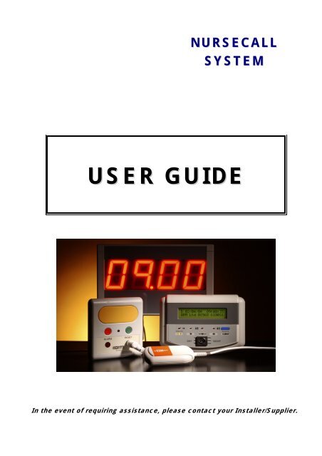
NURSECALLSYSTEM<strong>USER</strong> <strong>GUIDE</strong>In the event of requiring assistance, please contact your Installer/Supplier.
2 Display Operation .There are two types of display – Remote & Internal.Panel with StandardRemote Master DisplayPanel with InternalMaster DisplayConfigurationEditing buttonsSystemStatus LED’sKeyswitch set to “Enable” allows access to thesystem’s configuration filesWhen the keyswitch is in the enable position, the Silence Buttonis used to access the configuration menu.2.1 Operation.For normal operation (no calls or alarms on the system) the panel display will show:‘D’ = Keyswitch in Day mode‘N’ = Keyswitch in Night modeD 20/05/06 14:04‘Agents Name & Phone Number’From time to time the Rx & TX leds will flash indicating that the system and devices are communicating.2.2 Day/Night Mode.The keyswitch on the front of the display module has 3 settings:- Day- Night- EnableDay and Night settings are for the normal operation of the system and are indicated by a D or N at the top left ofthe display. These settings influence the type of response the system will show for any alarm, call or fault thatoccurs on the system.In Night mode a quieter sounder is used for all Calls on the system & faults will be displayed but without the soundermaking a noise.The Enable key position activates the buttons on the front of the display such that system parameters may bechanged. The Silence button does not silence the sounder in this mode, but instead is used to access the menustructure.For Normal Operation the keyswitch should be in the Day / Night position and the light above the Enablebutton should NOT be lit.5
2.3 Calls On System.In the event of a Call signal being sent by a unit the display will, for example, show:ROOM 4STAFF CALLROOM 4C XX DATE TIMECall/<strong>Alarm</strong> Level indicator:C = CallA = <strong>Alarm</strong>F = FaultWhere C = Call (A=<strong>Alarm</strong> for emergency, F = Fault), XX is the sensor number and the Time & Date of each Call aredisplayed. The bottom line of the display will alternate between displaying ‘STAFF CALL’ and ‘C XX DATE TIME’.2.4 Control Panel/Display Sounders.The Control Panel/Display sounders will make a different noise depending on what type of Call/<strong>Alarm</strong> is on thesystem, so staff can audibly differentiate between the Call types:CALL TYPEPatient CallStaff Call / AssistEmergency / AttackSOUNDER TYPESlow IntermittentFast IntermittentOn ConstantThe panel will return to normal operation only when the unit sending the call has been reset.2.5 Silence Button.Pressing the Silence button on any of the Display units when a Call/<strong>Alarm</strong> is on the system will cause all the soundersto remain quiet, the Call/<strong>Alarm</strong> information will still remain on the Displays.If a Call/<strong>Alarm</strong> remains unanswered, the sounders will resound after 4 minutes to remind staff that the Call stillneeds attending to. Emergency / Attack alarms will cause the panel to resound after 1 minute. (Sounder silencetimes are configurable)If the Silence button has been pressed following a Call, and then another Call comes onto the system, the Sounderswill re-sound to advise staff that there is another Call which needs attending to.2.6 Pagers.If Staff Pagers are incorporated into the system, then any Calls/<strong>Alarm</strong>s that are generated onto the system will berelayed directly to the pagers, enabling Staff to see the locations of calls without having to return to a central DisplayUnit.The pagers will display the Location & Type of Call/<strong>Alarm</strong> just as the Display Units willi.e.BLUE BATHROOMEMERGENCYIf a Call/<strong>Alarm</strong> remains unanswered the Pagers will be re-paged every minute, to remind/advise Staff that the Callstill needs attending to; this will occur until the unit has been reset.6
3.5 Infra Red Sensor.If a Call Point has an Infra Red sensor it can be remotely activated by activating an Infra Red trigger device (i.e.BeltClip / Pendant / Keyfob). Simply point the IR trigger unit at the Call Point and press the Assist / Emergencybutton.(Note: Call Points without an Infra Red sensor cannot be remotely activated)After an <strong>Alarm</strong> activation from an Infra Red trigger device (i.e. BeltClip / Pendant) it will be necessary to reset anyCall Points that have been activated.Point the front of the alarmed Infra Red trigger device at the Call Point then Press & Hold the Blue Reset button onthe IR trigger device for approximately 5 seconds, until the IR trigger device emits a Double beep and the LED on theCall Point stops flashing.If using Keyfobs, point a Staff Keyfob at the Call Point and press the Blue reset button until the Call Point resets.Alternatively once all IR trigger units have been reset, then press the Green Reset Button on the front of the CallPoint to reset it.3.6 Infra Red Ceiling Pull Cord.The Infra Red Remote Ceiling Pull Cords are monitored by the Call point on thewall in the ensuite/bathroom.If the Infra Red Ceiling Pull Cord is pulled it will transmit an infra red signal to the Wall Unit and activatea Call on the NurseCall system.The Nurse Call system will then display the location of the Call.BED 1 WCCALL SHOWERTo Reset the Call simply press the Green Reset button on the Call PointLow Battery.If the battery in the Ceiling Pull Cord runs low you will see aBED 1 WC“CHECK C/PULLCORD” fault message. Unscrew the top of theCHECK C/PULL CORDCeiling Pull Cord and replace the battery.Battery part number: BAT-AA-CPC8
4 Door Monitors .The Door <strong>Monitoring</strong> units will monitor doors to detect when they are opened and alert staff of any unauthorised use.The Door Monitor unit also doubles as an extra Call Point with fully functional Big Yellow Call and Red Emergencybuttons.Staff Override Keyswitch4.1 Arming. - close the door then turn the keyswitch on the unit to thevertical position. If the door is now opened the door monitor will beep and flash itsLED and send a Door Open signal to the control panel.FIRE EXITDOOR OPEN4.2 Staff Override. (Disarming) - to disarm the door, turn the keyswitch to the horizontal position.This disables the door monitoring function and allows the door to be opened without activating an alarm.It may be required to disarm the door monitoring function at times, especially if you are using a door constantly anddo not want it to send an alarm to the system every time the door is opened.Remember to re-arm the Door Monitor once finished.4.3 Staff Call. - Press the large Yellow button on the front of a wall unit.4.4 Emergency Call. - Press the Red button on the front of a wall unit.Both Staff & Emergency calls can be activated with the Door Monitor keyswitch in either position.4.5 Reset. – press the Green Reset button on the front of the unit4.6 Door Bell.The Door Monitor units can also be interfaced with a Door Bell, to enable visitors to notify staff that they are waitingat the Front Door.Pressing the Door Bell will activate the Door <strong>Monitoring</strong> unit and transmit a Callsignal to the Control Panel.Upon answering the door, reset the Door <strong>Monitoring</strong> unit in the normal wayMAIN ENTRANCEDOOR BELL9
5 Battery Replacement .The Low Battery warning comes 30 days prior to the battery reaching a level which may cause the unit not to workproperly any more.The Call Points require one battery per unit: re-order code: BAT-AANC.For old style Call Points please order BAT-AALTo replace the battery in the Call Points, firstly remove the unit from its bracket.• To do this simply push the Locking Tab at the base of the bracket towards thewall and at the same time slide the unit up and off the bracket.• Turn the unit over and remove the back cover.• To do this pull the tab at the top of the cover down and atthe same time push on the bottom right hand corner of thecover, this will release the cover so it can be removed.• Remove the exhausted battery and dispose of in a safe way and replacewith a new battery.• Ensure that the pins on the unit PCB are lined up with the holes on the battery PCB and insert thenew battery• If the battery is inserted correctly the unit should beep and a small bright green LED, located to the left ofthe battery, will flash.• Replace the back cover, ensuring that the battery PCB is lined up with the holding slot on the underside ofthe cover.• To reattach to the unit to the bracket line up the slots on the back of the unit and slide down until thelocking tab clicks into place.10
6 User Menu .The User Menu enables the following parameters to be modified/interrogated:• Unit Isolation• Time• Date• Battery Log• Print the Event Log• Sensor Name• Patient Name (only used on systems with Resident IR key fobs)• Staff Name (only used on systems with Staff IR key fobs)Access to the User Menu is done using the keyswitch and buttons on the front of the Master Display Unit:Keyswitch set to “Enable” allows access to thesystem’s configuration filesNavigation Keys used to scrollthrough Menu HeadingsConfigurationEditing buttonsSystemStatus LED’sSelection Keys used to scrollUp /Down through options• Turn the keyswitch on the Display unit to the Enable position (ensure light above enable lights up).• Press the Silence button to select the User Menu.• Then press the (up arrow) key above the Enable light to enter the User Menu.6.1 To Isolate a Faulty Unit.• Enter the User Menu• Press the Silence button until the display shows:ISOLATE SENSORON “Sensor Name”This menu allows individual sensors to be isolated from System Operation.• Use the Selection Keys to scroll through the sensors on the system.Up arrow above Enable light to navigate up through Sensor list.Down arrow above TX light to navigate down through Sensor list.• Use the key (Printer key) to turn a Sensor ON or OFF.Note: If the sensor was in fault at the time it was isolated it will be necessary to reset the Fault message by turning the keyswitch toNight and then back to Day.• The display will then show:as a reminder that a unit has been taken off the system.1 Isolated• This unit can now be sent for repair/replacement, the system will ignore that it is missing from site until ithas been returned and can then be un-isolated.11
6.2 Setting the Time.• Enter the User Menu.• Press the Silence button until the display shows:(with the cursor flashing on the hour)CHANGE TIMETime 07.30• Use the Selection Keys (above TX & Enable) to change the time and press the key (Printer key) tomove the cursor between the hour and minute fields.Note: To save the changes to the Time press the Silence Button once the new time has been entered.6.3 Setting the Date.• Enter the User Menu.• Press the Silence button until the display shows:CHANGE DATEDate 30/01/06(with the cursor flashing on the day)• Use the Selection Keys (above TX & Enable) to change the date and press the key (Printer key) tomove the cursor between the day/month/year fields.Note: To save the changes to the Date press the Silence button once the date has been entered.6.4 Sensor Battery/Signal Strength Log.• Enter the User MenuBATTERY LOG / Print3.5V “Sensor Name”• Press the Silence button until the display shows:• Use the Selection Keys (above TX & Enable) to scroll through each sensor to view the battery volts.• If a Printer / PC is connected then the Battery/Signal Strength Log for all the sensors may be printed out bypressing the key (Printer key).This prints:Sens - Sensor Number - Sensor Number allocated to each UnitBatt - Battery Voltage - Last received Battery VoltsTIME - Current Time - Time Count since last receptionLst - Last - Last Time Interval between receptionsMax - Max Time - Maximum Time between receptionsRSSI - Average Signal Strength - Average Signal Strength of UnitsNote 1: Sensor numbers 235 to 266 relate to the Control Panels.Note 2: The Last & Max times are historic Values.6.5 Event Log.• Enter the User Menu• Press the Silence button until the display shows:EVENT LOGSelectsPrints• Press the Selection key above TX light go back in time to view past events.• If a Printer / PC is connected the Event Log may be printed out from the historic event selected in thedisplay up to the present date by pressing the Printer key12
6.6 Edit Sensor Names.Plug the keyboard into the socket on the base of the display.(for panels with embedded displays the keyboard socket is inside the panel on the back of the display PCB)• Enter the User Menu• Press the Silence button until the display shows, for example:Serial Number of unitSn_014600L_Room 4Sensor_001Sensor Number of unitUnit Location Label• Then Unlock the Memory for editing (see Appendix A)• If you know the Serial number of the unit whose label you wish to change, type it in on the keyboard, thenpress Return. The units’ Sensor number and existing Label will be displayed. Press Return twice to move to the“L_xxx” field (Location Label).• If you do not know the Serial number of the unit whose label you wish to change, but you do know the Sensornumber, press Return on the keyboard to move the cursor to the next field, then type in the Sensor number ofthe unit and press Return.• Type the new label that you wish the unit to have and press Return to save it.• If the new label is shorter than the old label, use the space bar key to remove leftover characters.• Remember to re-lock the Memory (see Appendix A)• If you do not know either the Serial or the Sensor Number of the unit whose label you wish to change, pressReturn so that the Sensor field is highlighted and use the Selection keys (above TX & Enable) to scroll up anddown through the units on the system until you reach the unit that needs changing.• Once you have reached the unit that you wish to change the label for, press Return on the keyboard tomove to the bottom line (Location Label field) and type the new label that you wish the unit to have,press Return to save the new label.• If the new label is shorter than the old label, use the space bar key to remove leftover characters.• Remember to re-lock the Memory (see Appendix A)• To EXIT the <strong>USER</strong> Menu, turn the Keyswitch to Night and then back to the Day position.6.7 Patient Name.Patient Keyfobs can be personalised with the Patient’s name if required. (default setting is Patient 1,Pateint 2 etc etc)• To rename a Patient Keyfob plug the keyboard into the socket on the base of the display.(for panels with embedded displays the keyboard socket is inside the panel on the back of the display PCB)• Enter the User Menu• Press the Silence button until the display shows, for example:Keyfob namePATIENT NAME 1PATIENT 1Patient Keyfob sensor number• Then Unlock the Memory for editing (see Appendix A)13
• Press the buttons above TX & Enable lights, to scroll through the Keyfob sensor numbers until to reachthe keyfob number that you want to change the name for.• Type the new name and use the space bar to over type any remaining characters from the previous label.• Press Return to save the new name. Once finished editing all the names remember to re-lock thememory (see Appendix A).• To EXIT the <strong>USER</strong> Menu, turn the Keyswitch to Night and then back to the Day position.6.8 Staff Name.Staff Keyfobs can be personalised with the Staff’s name if required. (default setting is Staff 1,Staff 2 etc etc)• Follow the same procedure as for editing Patient Keyfob names (Section 12.7 above)• the display you require is:Keyfob nameSTAFF NAME 0STAFF 0Staff Keyfob sensor number• Remember to re-lock the memory once finished (see Appendix A).14
7 TROUBLE SHOOTING .In the event of a system fault, please firstly refer to the Common Issues below. Ifyou then require assistant please contact your Installer/Supplier.CONSTANT PATIENT CALLS.Fault: The wall unit sends a Patient Call. When reset is pressed, the system Resets but goes straight back intoalarm with patient call.Cause: If the unit is a Pull Cord check the cord is free and that the internal switch is operating freely. If it isjammed, release the cord.CONSTANT STAFF CALL OR EMERGENCY CALL.Fault: The Wall Unit sends Staff Call or Emergency. When reset is pressed, the system Resets but goes straightback into alarm with Staff Call or Emergency.Cause: Check the Yellow (Staff Call) and the Red (<strong>Alarm</strong>) buttons are free. Check the label on the front of the unit isnot holding down the buttons. This label is a sticky label and may be removed and repositioned.CONSTANT BLEEPING FROM A UNIT.Fault: The Wall Unit bleeps constantly.Cause: Check the Reset button operates freely. Check the label is not holding the button down.If unit is still bleeping change the batteryUNIT CALLS BUT DOES NOT RESET.To temporarily minimise the nuisance effect of this fault, the faulty unit should be isolated via the User Menu andreplaced with a spare unit until the faulty unit can be repaired/replaced.LOW BATTERY.Fault: Low Battery is indicated on the Control Panel against a Unit location.Cause: The Unit’s battery is low and its internal battery should be replaced.RF FAIL.Fault:RF Fail / RF FLT is indicated on the Control Panel against a Unit.Cause: The Unit has failed to communicate with the Control Panel. Put the unit in question into alarm and thenreset it. If the alarm is NOT received or the unit does not Reset, then firstly change the battery and retry. If the unitstill does not work properly then it will need to be replaced.A ‘RF Fail’ fault will also show if any of the systems’ units are taken away from site without firstly isolating them fromthe system.IR FAULT.Fault: IR/FLT is indicated on the Control Panel against a Unit location.Cause: There is a fault with the units’ Infra Red sensor. Isolate the unit via the User Menu and return the unit forrepair.CHECK C/PULLCORD FAULT.15
Fault: CHECK C/PULLCORD is indicated on the Control Panel against a Unit location.Cause: The infra red Ceiling Pull Cord unit has failed to check in with the Wall unit.1. Firstly check to see if the Pull Cord triggers the wall unit.2. Check the Wall unit actually works.3. Replace the battery in the Ceiling Pull Cord.FAULT WARNINGS ON DISPLAY.If a fault appears on the system the display will show, for example:ROOM 4LOW BATTERYROOM 4F XX DATE TIME(or RF/FLT, T/FLT, IR/FLT instead of LOW BATTERY)where F = fault and XX is the sensor number. The lower line of the display will alternate between the type of fault(i.e. LOW BATTERY) and details of the faulty unit (F XX DATE TIME).DAY MODE:If the panel is in the DAY mode the Internal Buzzer will sound intermittently, pressing the Red Silence Button willcancel the buzzer but the fault will continue to be displayed.NIGHT MODE:If the panel is in NIGHT mode then the fault will only be displayed and the panel will be silent.16
8 Service and Maintenance .All Units on the system will periodically transmit their status to the Control Panel, enabling the system to monitor thefunctionality of all units on the system.The Control Panel will also monitor the battery levels of all the units incorporated into the system and notify you ofany Low Battery faults when they arise, giving you 30 days notice before the battery becomes too low.If a fault or low battery is detected the Display will show the Sensor number and it’s location along with the fault.For information about replacing the batteries in the various units please see Battery Replacement at the end of therelevant sections.For faults firstly refer to the Trouble Shooting section, if the fault persists then contact your Installer/Supplier.Do not remove any of the Call Points from the site as this will cause the control panel to raise a warning that a unitis missing (RF Fault will be displayed)We recommend that you have your system serviced once a year to meet with Care Standards requirements and atleast once every three years to replace all system batteries.17
APPENDIX A: Unlocking & Relocking Memory .Unlocking Panel Memory.Before Editing Unit names, the memory must be “enabled”. To do this, Open Control Panel door and move thejumper on LK1 so that it connects both “B” pins. When the memory is “enabled” the memory LED illuminates on newpanels only. (see below)To “Enable Memory”, amemory jumper must connectboth “B” pins on LK1.When the Memory is“Enabled” this LED illuminates(New panel versions only)NOTE: (LOCKING MEMORY)To Lock Memory after programmingremove the jumper from both “B” pins,(the Memory LED will turn off) and parkthe jumper on one pin only for future use.NOTE:If the control panel board has a different layout from the above images, then see below for older panelversions.18
Older Versions of Control Panels.1.)Link 1(Memory Enable).Place jumper onboth pins.NOTE: (LOCKING MEMORY)To Lock Memory after programming remove the jumper from both pins and park the jumper on onepin only for future use.2.)Link 2(Memory Enable).Place jumper ontop 2 pins.NOTE: (LOCKING MEMORY)To Lock Memory after programming remove the jumper from both pins and park the jumper on onepin only for future use.19