User Guide - Alarm Radio Monitoring Ltd
User Guide - Alarm Radio Monitoring Ltd
User Guide - Alarm Radio Monitoring Ltd

Create successful ePaper yourself
Turn your PDF publications into a flip-book with our unique Google optimized e-Paper software.
Contents1. General <strong>Radio</strong> Systems2. Basic Operations2.1 Normal2.2 Fault2.3 <strong>Alarm</strong>2.4 Evacuate2.5 Alert2.6 Silence2.7 Reset2.8 Print3. Advanced Operation3.1 Main Menu3.2 Isolate / Enable Devices3.3 Test Modes & Options3.4 Change Options3.5 Event Log4. Fire <strong>Alarm</strong> TestingAppendix:<strong>Alarm</strong> & Fault Code List
1.0 GeneralElectro-Detectors has drawn from over eight years experience of manufacturing radio fire alarmsystems and has taken into account the changing requirements of the market place to producea system offering greater controllability of devices from the control panel. The MILLENNIUMsystem is a worthy successor to the well-established EDA series. At the heart of theMILLENNIUM system is a compact control panel designed around a 16-bit processor andfeaturing surface mount technology. 16 times more powerful than its predecessor and capableof supporting 3 times the number of devices, the panel benefits from well designed and clearlylabelled operational features. Versatile software means that the millennium will interface readilywith most other hardwired systems and is user friendly. Programming of devices can be carriedout by either direct use of the internal keypad or via the PC interface. Excellent message qualityis achieved as a result of a CCFL backlit 8 line liquid crystal display. As with all Electro-Detectors products, build quality is stringently controlled at every stage ensuring completereliability of the system during operation.The fire alarm installed is a fully addressable radio system. Each device is individuallyidentifiable by means of a unique unit number between 1 and 3000 inclusively. There is nowiring between units, control panels and sounders, the system communicating via short waveradio transmissions. No other radio equipment will interfere with the system and, likewise, thefire alarm will not interfere with any other radio equipment.For smaller installations a system has been designed to cater for 999 devices in twenty zones.The panel uses a smaller LED backlit 4 line liquid crystal display. This panel operates in asimilar manner to other panels but has some sophisticated functions omitted.The operation of the system is dependant on the configuration, set by the commissioningengineer, but each installation is generally similar.When a smoke or heat detector detects an alarm condition or a break glass unit is operated, therelevant information will be displayed on the control panel. This includes the device location,unit number and zone of alarm. The sounders will operate. The situation should be investigatedfor the cause, and once under control the system can be silenced.Any subsequent alarm will operate the sounders once more and the relevant information for thenew alarm being displayed on the screen.If the system detects any faults on any of the devices or the control panels e.g. mains fail or unitremoval, a fault will be displayed. A buzzer will sound on the control panel to attract someone’sattention. This can be silenced until the cause of the problem is corrected.For further operation of the system refer to the remaining sections of this manual.If you have any queries on the operation of the panel, please contact the company thatmaintains the system, printed on the reverse of this manual.If a particular option is not available, a suitable message will be displayed.
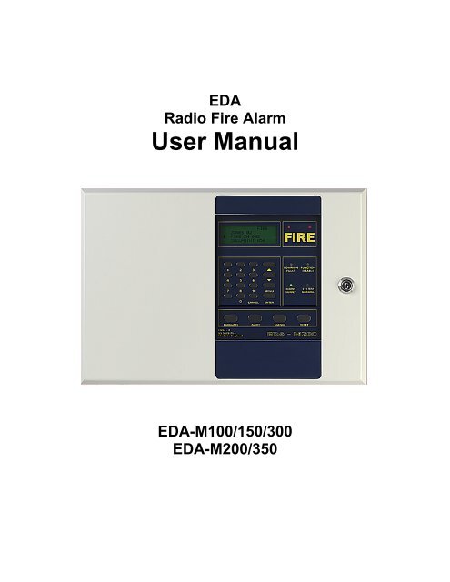
2 Basic OperationIn order to operate the panel the front panel door will have to be unlocked.(Note: This section describes operation of a system with standard configuration.Operation is for the EDA-M100 and EDA-M150 unless otherwise stated)EDA-M100 and EDA-M150EDA-M2002.1 Normal When no faults or alarms are being displayed, the display will appear dark. Thecurrent time and date are displayed in area (3), not available on the EDA-200. Theinstalling agents name and telephone number will be displayed in area (2).Whenever a radio message is received or transmitted the appropriate Rx or Tx box(1) will flash. Nothing will be displayed in area (4). The system Normal LED (6) willbe illuminated. The mains supply light will be illuminated indicating the supply ishealthy.2.2 Fault When the panel detects a fault condition the internal buzzer will soundcontinuously and the common fault light will illuminate. The display back light willbe switched on and the initial fault will be displayed on the first line, as shown inthe example below. The display will detail the type of fault, which device and whenit occurred. If programmed, a text location will be displayed below. The EDA-M200is not capable of detailing dates and times for any of its events.Any subsequent faults will be displayed, and scroll through, on the bottom twolines of the display. The EDA-M200 will only display one fault at a time.Each fault is visible for a short period of time. Pressing the ↑ and ↓ keys will causeeither the previous or the next fault to be displayed. This will then continue to scrollfrom the event being displayed. It is possible for 300 faults to be scrolled through.Area (3) will alternate between the total fault count and the date and time. Theinstalling agents name and telephone number remains in area (2) of the display. Inorder to conserve power the LCD backlight will switch off 15 minutes after a faultoccurs on any panel.If the mains supply is interrupted the fault will be indicated as above and the MainsSupply light will be extinguished. For a complete list of faults see appendix.
1ST ZN LAST ZN TOTAL04 04 011 ZONE 04 HEAT 003Second floor outsideExample - <strong>Alarm</strong> Display for EDA-M200Text Line scrolls across theLCD2.4 Evacuate Pressing the evacuate button will operate the sounders, if they are not alreadysounding. This will override an intermittent sounding alarm. ‘Evacuate’ will bedisplayed on the display along with the panel number where the button waspressed. The text location for this panel and the date and time is displayed. Abuzzer on the control panel sounds continuously. By default the AUX relays 1and 4 operate but may be redefined using the PC software.2.5 Alert The alert function is designed as a warning. Pressing this button will cause thesounders to sound an intermittent tone. It will not override an evacuate or alarmtone, but will be displayed on the screen in a similar way to the Evacuatemessage. The buzzer sounds continuously whilst in this state. By default theAUX relay 2 operates but may be redefined using the PC software.2.6 Silence If the system is in an alarm or alert state, from either a smoke detector, breakglass or panel, pressing this button will silence the sounders. A message willappear on the screen indicating the operation is taking place. It can take severalseconds for the complete system to silence. An internal buzzer will now soundintermittently. A subsequent alarm condition from a different unit or pressingeither Evacuate or Alert will cause the sounders to re-sound.If a fault is being displayed operation of this button will silence the internalbuzzer. Any subsequent faults will re sound the buzzer.In both of the above situations the silence LED above the button will beilluminated. The events remain on the screen. On the EDA-M200 the LED’s arenot fitted and the status is indicated on the top line of the LCD.In alarm the silence operation by default clears the sounder relays and AUX 4;the AUX mask may be reconfigured using the PC software.2.7 Reset Once the system has been silenced, whether it be a fault or alarm condition, Resetwill cause the system to return to normal. The reset button is disabled for sixseconds after the silence has been pressed. The display will be cleared and amessage will appear indicating the system is resetting. If the alarms or faultspersist they will be redisplayed and actioned upon accordingly. If there were faultsprior to an alarm condition reset will cause the faults to be re-displayed.In alarm the reset operation clears AUX 1 and 3 by default but may be reconfiguredusing the PC.In fault the reset operation clears AUX 2 by default, but will clear the relaysprogrammed to operate on fault using the PC.Pressing Reset for 3 seconds in a system normal state will cause the lamps testfunction to operate. This will in turn flash all LED’s and flash the LCD.
2.8 Print Momentarily pressing the print button will print earlier events in reverse order aspreviously displayed on the screen, starting with the most recent event first. Whenthe required events have printed, a short press of the print button will cause theprinting to cease. The print operation will terminate automatically once the entirelog has been printed. A message appears on the LCD whilst the printer isfinishing. This will take a few seconds as printing is terminated and the paper is fedout. To feed the paper through the printer press and hold the print button for therequired amount of paper feed and then release the button. The printer is onlyavailable on the EDA-M150. If a printer is not fitted a suitable message will bedisplayed.
3.0 Advanced OperationThis section details use of the menus and the functions available to a user. A password isrequired to perform these functions. There are two levels of access, i/ a user and ii/ an engineer.The default user password for a newly supplied panel is 2222. If the password is forgotten anengineer will be required to gain access to the system to alter the user password.3.1 Main MenuTo enter the menu system press the button labelled menu. This function is disabled if thesystem is in an alarm condition. The display will prompt the user to enter a four digit password.There are five attempts to enter the correct password. If after five times the password is still notcorrect, the menu button will be disabled for thirty minutes.Once entered correctly the system will display momentarily that entry has been granted to auser and how many failed access attempts since the last entry. The main menu, detailed below,will now be displayed.If the menu system is entered and no keys are pressed for five minutes, which can be adjusted,the menu will cancel.All menus operate in the same basic manner. The highlighted bar can be moved up and downusing the ∧ and ∨ keys. Pressing enter will then select this option. The scroll bar will wrap roundthe screen. For example, to select Change Options press the ∨ key until Change Options ishighlighted and press Enter. Alternatively the number preceding the option can be pressed forfast access. On the M200 panel the menu bar is not featured and therefore the menu item mustbe selected using the numeric keys.To exit completely from the menus to the system display press cancel.To return to the previous menu press 0.<strong>Alarm</strong>s will override the menu system. New faults will cause the buzzer to sound and theappropriate LED’s illuminate but will not override the menu. The buzzer can be silenced bypressing silence. The faults will be displayed when the user exits the menu.MAIN MENU1. Isolate / Enable2. Test Modes & Options3. Change Options4. View Event Log0. ExitUse ↑↓ to highlight and press enter toselectMain Menu for EDA-M100 and EDA-M1501.Isol Dev2.Isol Zone3.Isol Aux4.Event Log5.TestCancel-ExitMain Menu for EDA-M200
3.2 Isolate / Enable DevicesSingle units or areas of units can be disabled by using this function. For example, if somewelding work was being performed that could possibly operate some detection units, then theseunits could be isolated. Both individual units and areas of detectors can be isolated through thismenu.A pulsed panel buzzer is active while devices are isolated which can be silenced by pressingthe Silence key while no faults or alarms are being displayed.Both Fault and alarm conditions are disabled through this function.When the system is set-up, a time limit is programmed to automatically re-enable any isolateddevices or zones when the period has expired.A maximum of fifteen devices and fifteen zones can be isolated at any one time. Fifteenauxiliaries can also be isolated.enter to selectISOATE / ENABLE1. Isolate Detector2. Enable Detector3. Isolate Zone4. Enable Zone5. Isolation of Aux0. ExitUse ↑↓ to highlight and pressIsolate DevEnable DevWhen this function is selected a list of the currently isolated devices isdisplayed. The user is prompted to enter the unit number of the device to bedisabled. Units 1 to 3000 can be disabled. A four digit number can be enteredor a one, two or three digit number followed by enter. The unit number will beadded to the isolated list of devices. All units except sounders and actuatorscan be isolated. To exit from this screen press cancel. Devices that do notexist on the system can not be isolated.On selecting this function a list of isolated devices is displayed, the first in thelist being highlighted. To enable a device, use the ∧ and ∨ keys to select theunit to be enabled and press enter. This unit will now be enabled and will beomitted from the list.Isolate Zone This operates in the same way to the isolation of a detector. Zones 1 to 999can be isolated. If a zone is isolated call points will still operate buttransmitters, smoke and heat detectors will be isolated.Enable ZoneIsolate AuxThis operates in the same way to enable detector.The auxiliary relays on panels can be isolated. Either an individual panel canbe isolated or all of the panels. The user is prompted to enter a two digitnumber relating to the panel number to be isolated. Entering 00 isolates allpanels. A total of fifteen panels can be isolated at any one time. To enable thepanels, press the ∧ or ∨ keys until the required panel to be enabled ishighlighted and press enter.
Isolating and enabling devices, zones and auxiliaries on the EDA-M200This is similar to the EDA-M100 and EDA-M150. Once the option is selected units and zonescan be isolated and enabled on the same respective screen. Devices do not have to be loggedto the system to be isolated. To isolate a device or zone select the appropriate option and enterthe number followed by return. The isolated number will be displayed below. To isolate othernumbers repeat the operation. To enable the zones or devices select the appropriate option andusing the ∧ or ∨ keys position the cursor on the number to be enabled. Press enter to enablethe number. The EDA-M200 panel only has the ability to communicate with 999 devices in 20zones.3.3 Test Modes & OptionsThe test mode facility allows the system to be tested with the minimum of disruption to thepremises. The options are displayed below.All test modes will automatically re-enable themselves if more than 30 minutes elapses after thelast activation. This value can be altered to a new setting by an engineer. The timeout setting isdisplayed on the menu screen. On the EDA-M200 the timeout is not labelled but is located inthe bottom right of the screen.A pulsed panel buzzer is active while in test mode but can be silenced by pressing the Silencekey while no faults or alarms are being displayed.To activate any of the test modes either highlight the option using the ∧ and ∨ keys and pressenter or press the appropriate number. The new status will be displayed to the right hand side ofthe line. To enable the test modes Exit and save must be selected. Pressing cancel will not alterthe test mode status. On the EDA-M200 options are selected by pressing the appropriatenumber. The test menu on the EDA-M200 is available as option 5 from the main menu. Thetest menu is relocated when accessed as an engineer - see section 7.0.TEST MODES & OPTIONS1. Test Off2. Aux Isolated3. Auto Silence Off4. Zone All0. Exit & Save Timeout:030minUse ↑↓ to highlight and press enter to selectMenu for EDA-M100 and EDA-M1501.Test OFF2.Aux ENAB3.A.Sl OFF4.Zone ALARM5.BellsENAB0.Done030minMenu for EDA-M200TestAuxWhenever a test is being carried out, for the system to see the event as aroutine test, this option should be selected. The default is off.This option allows the auxiliary relays on all panels to be isolated or enabled.The default is enabled.
Auto SilenceWith this option all sounders will silence automatically after 6 seconds. Therewill be a slight delay before all sounders silence.Zone of <strong>Alarm</strong> With this option enabled only sounders in the area of testing will operate. Thiscan be used in conjunction with the auto silence option.3.4 Change OptionsThis function is not available on the EDA-M200 panel.Selection of this displays a sub-menu allowing the user to change the date, time and userpassword. The menu is shown below.Change Options1. Change Date and Time2. Change <strong>User</strong> Password3. Change Language0. ExitUse ↑↓ to highlight and press enter toselectDate and Time<strong>User</strong> PasswordLanguageTo change the date and time select option 1. Use the ∧ and ∨ keys tohighlight the figure to be changed. Press enter to select the figure and it willstart to flash. Use the ∧ or ∨ keys to change the value and press enter whenfinished. Once the date and time are correct select ‘accept’ and press enter.Pressing cancel will exit without making any changes.To change the users password select option 2. The user will be prompted toenter the new password and then to re-enter the new password again. If thetwo passwords agree the password will be changed otherwise the oldpassword will be reverted to. Passwords are at no point visible on thesystem. If the password is forgotten an engineer will have to be called to seta new password.Not implemented3.5 View Event LogThe event log is the history of all operations that have taken place on the system. The 300 mostrecent events are stored. The information displayed includes an event number, the event type,the device number, the location, the date and the time the event occurred. By selecting thismenu the following sub-menu appears. This allows you to selectively view events. If an option isnot available a message will be displayed.VIEW EVENT LOG1. All Events2. Test Events3. Engineering Events4. Real Events5. Fault Events0. ExitUse ↑↓ to highlight and press enter toselect
Viewing the events, using any of the above options is essentially the same. Once selected themost recent event will be displayed as shown below. By using the ∧ or ∨ keys, the event log canbe scrolled through to examine all events. If there is no event displayed with the event numberthen the end of the log has been reached. Pressing cancel will return to the menu. Whenviewing events other than ‘all events’ some events may appear blank. These are events notrelating to the search selected.View All Events3 Low Battery Smoke Detector 0143 12:33 21-11-991st Floor South Wing Outside Room 122 Unit Removal Callpoint 0142 12:34 21-11-99Ground Floor Main Entrance Opposite Reception∧ , ∨ Scroll, Cancel - ExitAll events will be displayed including silence alarms, silence faults and resets.AllTestEngineeringRealAll events will be displayed including silence alarms, silence faults and resets.Only events that were performed in a test mode will be displayed.Only events that were performed by an engineer will be displayed.Only real events will be displayed i.e. events that occurred whilst not in a testmode or an engineering mode.To view the event log on the EDA-M200 select the appropriate option. There are no options forviewing particular events. Use the cancel key to exit from the event log.
Appendix:<strong>Alarm</strong> & Fault ListPanel <strong>Alarm</strong>sEvacuate Control XXAlert Control XXFire Zn XXX Control XXEvacuate pressed on panel number XXAlert pressed on panel number XXFire event generated from CP inputPanel FaultsC (Displayed in Zone Number) Processor FailureInterference 1 Control XXInterference on panel frequencyInterference 2 Control XXInterference on device frequencyTx/Rx Fail 1 Control XXTransceiver fail on panel frequencyTx/Rx Fail 2 Control XXTransceiver fail on device frequencyMains Low Control XXMains supply below 195V ACMains High Control XXMains supply above 255V ACBatt Low Control XX Battery voltage below 8.5VBatt High Control XXBattery voltage above 15VOC Flt Ant Control XXAntenna Open circuitSC Flt Ant Control XXAntenna Short circuitOC Flt Snd 1 Control XXSounder 1 Open circuitSC Flt Snd 1 Control XXSounder 1 Short circuitOC Flt Snd 2 Control XXSounder 2 Open circuitSC Flt Snd 2 Control XXSounder 2 Short circuitOC Flt Snd 3 Control XXSounder 3 Open circuitSC Flt Snd 3 Control XXSounder 3 Short circuitOC Flt Snd 4 Control XXSounder 4 Open circuitSC Flt Snd 4 Control XXSounder 4 Short circuitWire Fault Control XXMonitor Input Open circuitOC Flt CP Control XXExternal Callpoint Open circuitSC Flt CP Control XXExternal Callpoint Short circuitComms Fl XX Control YYPanel YY has failed to communicate with panel XXDisp. Fail Control XXFailure of main panel displayDevice <strong>Alarm</strong>sFire Zone XXX Smoke Det XXXXFire Zone XXX Heat Det XXXXFire Zone XXX Callpoint XXXXFire Zone XXX Sounder XXXXFire Zone XXX Wire Cct XXXXFire Zone XXX External XXXXFire Zone XXX Trans. XXXXSmoke detector fire eventHeat detector fire eventCallpoint fire eventSounder CP input fire eventEDA400 wired interface fire eventExternal wired interface fire eventTransmitter fire eventDevice FaultsVerify Fail Smoke Det XXXXUnit Removal Callpoint XXXXBatt 1 Low Sounder XXXXBatt 2 Low Sounder XXXXBatt Low Smoke Det XXXXInt. Fail Sounder XXXXOC Flt Callpoint XXXXSC Flt Trans. XXXXExtnal. Flt Sounder XXXXTX/RX Fail Sounder XXXXWire Fault Smoke Det XXXXType Error Callpoint XXXXVerify Fail (Smoke, Heat, Callpoint, Sounder, Trans.)Unit Removal (Smoke, Heat, Callpoint, Sounder, Trans)Main Battery low (Sounder)Standby Battery Low (Sounder)Battery Low (Smoke, Heat, Callpoint, Transmitter)Processor Failure (Sounder)External Open Circuit Wire Fault (Callpoint, Trans.)External Short Circuit Wire Fault (Callpoint, Trans.)External Fault (Sounder)Transmitter/Receiver Failure (Sounder)External Wire Fault (Smoke, Heat, Sounder)Device type is different to that specified in option