Nova Woodlathe Cast Iron Stand - Teknatool
Nova Woodlathe Cast Iron Stand - Teknatool
Nova Woodlathe Cast Iron Stand - Teknatool
- No tags were found...

Create successful ePaper yourself
Turn your PDF publications into a flip-book with our unique Google optimized e-Paper software.
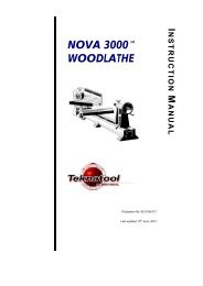
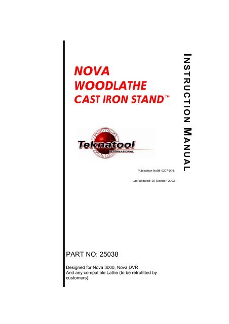
NOVAWOODLATHECAST IRON STAND Publication No98-0307-004.I NSTRUCTION M ANUALLast updated: 29 October, 2003PART NO: 25038Designed for <strong>Nova</strong> 3000, <strong>Nova</strong> DVRAnd any compatible Lathe (to be retrofitted bycustomers).
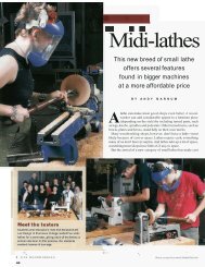
<strong>Nova</strong> <strong>Woodlathe</strong> <strong>Cast</strong> <strong>Iron</strong> <strong>Stand</strong> FeaturesROBUST CONTRUCTION:The cast iron stand set comprises of two cast iron legs, one on either side,which are interchangeable. The stand pieces are cast from a high grade ofcast iron with extremely good section thickness and CAD generatedinternal gussets at all critical points to withstand extremely high stresseswith practically no distortion. <strong>Cast</strong> iron has always been the material ofchoice for wood lathe construction because of its inherent mass andexcellent modulus of vibration dampening.The cast iron stand has been purposely designed to be heavy, solidand robust keeping this in mind.1
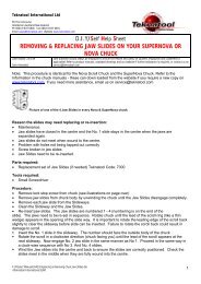
Fig 1: Exploded viewITEM NO. QTY. PART NO. DESCRIPTION1 2 25031 <strong>Cast</strong> <strong>Iron</strong> <strong>Stand</strong> Legs2 1 25035 <strong>Stand</strong> Tray3 8 NHZ12 M12 Nut4 2 BNMZ12025 Bolt M12 x 255 4 BNMZ12030 Bolt M12 x 306 2 BNMZ08020 Bolt M8 x 207 2 NHZ8 M8 Nut8 8 BNMZ12065 Bolt M12 x 659 8 FW12 Washer M1210 2 FFW08 Washer Fender M8 ZP"J" bolt Kit - Pre Oct 03 [2 feet] extensions onlyITEM NO. QTY. PART NO. DESCRIPTION1 1 NA M8 J bolt2 1 NA M10x 40 bolt3 2 NHZ10 M10 Nut4 1 NHZ8 M8 Nut2
ASSEMBLY INSTRUCTIONS:SAFETY: THE STAND AND LATHE ELEMENTS ARE HEAVY, PLEASE EMPLOY CORRECTLIFTING TECHNIQUES AND EQUIPMENT AND HAVE SOMEONE ASSIST. USE CORRECTTOOLS AND OBSERVE RECOMMENDED PRACTICES.Set up your workshop area before beginning assembly of the lathe standPlease follow the steps listed below for assembling the stand.1) Make the two stand legs stand upright facing each other at approximately the samedistance apart as the length of the lathe. The stand legs will stand upright on the two feetalthough not very stable, but this is enough to carry out the assembly. It is stronglyrecommended that two people are involved up to step 3, after which one person canfinish off the rest of the procedure.2) Assemble the tray item 2, (sloping away from you as shown in the exploded view) withthe M8 bolts, nuts and fender washers. You may have to adjust he length between thestand legs to align the holes. DO NOT tighten fully at this point. Now the tray will hold thestand legs together. The stand at this point will be a bit wobbly as the fasteners are notsecured completely. This initial set up enables the lathe to be placed on the stand.3) Before placing the lathe install the M10 bolt and nuts on the stand piece that has beendrilled to take the additional J-bolt clamping. (See Fig 4.) Adjust the M10 bolt right downso that it does not interfere with the web section on the extension bed. Now place thelathe on the two stand legs. Position the lathe bed and extension holes to match withholes on the stand legs. Place the M12 x60mm bolts (item 8) from the top (8 of them),except the two that are fastened from the bottom on the far left side of the main bed (usewashers on all bolts. The two bolts on the far left side directly fasten into the tapped holesin the main bed). Fasten the M12 nuts and washers (items 3 and 9) to the M12 x 60bolts. Tighten all M12 bolts and nuts firmly.Fig 3: Sketch showing assembly of additional J-bolt clamping on the web.J-Bolt gets fastened frombottom of the casting withan M8 nutM8 bolt placed under the web with oneM8 nut on either side of the casting.Place the bolt with the nut before startingthe lathe assembly.4) Attach the accessory fastening kit on the extension side as shown in picture (Fig 3) andtighten firmly.3
5) Fully tighten the M8 bolts and nuts on the tray.6) Now, with the help of a marking pen, mark the position for drilling holes into concrete floorfor securing the construction bolts. On the feet of the stand legs, there are two holes, one isan M12 tapped hole for the jacking bolts, the other is a plain 14mm hole for the constructionbolts. The position for construction bolts have not been shown in the exploded view.7) Once the hole positions have been marked, shift the lathe aside and install the constructionbolts. Refer to your supplier on the size of drill recommended for the construction bolts youbuy.8) Lift and position the complete unit over these construction bolts. Tighten all nuts firmly.9) Install all M12x30mm bolts (item 5) for jacking as shown in the exploded view in the M12tapped holes on each of the feet of the stand legs.10) Level the lathe bed with the help of the above jacking bolts with the help of a spirit level.11) Once the lathe has been leveled tighten all construction bolts firmly.12) Re-inspect to ensure all fasteners are firmly secured everywhere.13) The stand installation is now complete.4
<strong>Nova</strong> <strong>Woodlathe</strong> <strong>Cast</strong> <strong>Iron</strong> <strong>Stand</strong> ManualPublication Code: 98-0307-004© <strong>Teknatool</strong> International 20035 98-0307-004