Fundamentals of profibus pa networks - Krohne
Fundamentals of profibus pa networks - Krohne
Fundamentals of profibus pa networks - Krohne

You also want an ePaper? Increase the reach of your titles
YUMPU automatically turns print PDFs into web optimized ePapers that Google loves.
5<br />
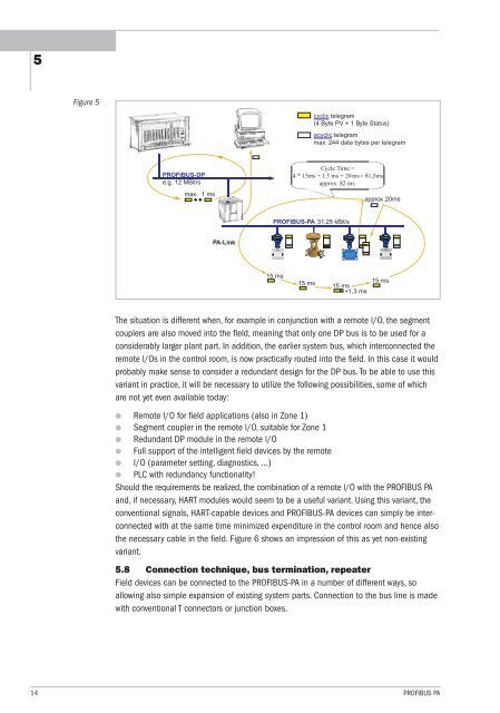
Figure 5<br />
3. Radar-Füllstandsmesssysteme<br />
PROFIBUS-DP<br />
e.g. 12 MBit/s<br />
max. 1 ms<br />
PA-Link<br />
PROFIBUS-PA 31,25 kBit/s<br />
acyclic telegram<br />
max. 244 data bytes per telegram<br />
approx.20ms<br />
15 ms<br />
15 ms<br />
+1,3 ms<br />
The situation is different when, for example in conjunction with a remote l/O, the segment<br />
couplers are also moved into the fleld, meaning that only one DP bus is to be used for a<br />
considerably larger plant <strong>pa</strong>rt. In addition, the earlier system bus, which interconnected the<br />
remote l/Os in the control room, is now practically routed into the field. In this case it would<br />
probably make sense to consider a redundant design for the DP bus. To be able to use this<br />
variant in practice, it will be necessary to utilize the following possibilities, some <strong>of</strong> which<br />
are not yet even available today:<br />
● Remote l/O for field applications (also in Zone 1)<br />
● Segment coupler in the remote l/O, suitable for Zone 1<br />
● Redundant DP module in the remote l/O<br />
● Full support <strong>of</strong> the intelligent field devices by the remote<br />
● I/O (<strong>pa</strong>rameter setting, diagnostics, ...)<br />
● PLC with redundancy functionality!<br />
Should the requirements be realized, the combination <strong>of</strong> a remote l/O with the PROFIBUS PA<br />
and, if necessary, HART modules would seem to be a useful variant. Using this variant, the<br />
conventional signals, HART-ca<strong>pa</strong>ble devices and PROFIBUS-PA devices can simply be interconnected<br />
with at the same time minimized expenditure in the control room and hence also<br />
the necessary cable in the field. Figure 6 shows an impression <strong>of</strong> this as yet non-existing<br />
variant.<br />
5.8 Connection technique, bus termination, repeater<br />
Field devices can be connected to the PROFIBUS-PA in a number <strong>of</strong> different ways, so<br />
allowing also simple ex<strong>pa</strong>nsion <strong>of</strong> existing system <strong>pa</strong>rts. Connection to the bus line is made<br />
with conventional T connectors or junction boxes.<br />
14 PROFIBUS PA<br />
15 ms<br />
� �� �� �<br />
1 2 3 4 5 6<br />
15 ms<br />
cyclic telegram<br />
(4 Byte PV + 1 Byte Status)<br />
Cycle Time =<br />
4 * 15ms + 1.3 ms + 20ms = 81,3ms<br />
approx. 82 ms<br />
�� � �� �<br />
1 2 3 4 5 6<br />
� �� �� �<br />
1 2 3 4 5 6