Jandy® Stealth - Home - Swimming Pool Parts Filters Pumps ...
Jandy® Stealth - Home - Swimming Pool Parts Filters Pumps ...
Jandy® Stealth - Home - Swimming Pool Parts Filters Pumps ...
- No tags were found...

You also want an ePaper? Increase the reach of your titles
YUMPU automatically turns print PDFs into web optimized ePapers that Google loves.
Page 3Table of ContentsSection 1. Important Safety Instructions ........... 41.1 Safety Instructions .......................... 41.2 <strong>Pool</strong> Pump Suction EntrapmentPrevention Guidelines ..................... 6Section 2. General Description .......................... 82.1 Introduction ..................................... 82.2 Description ...................................... 8Section 3. Installation Information .................... 83.1 Plumbing ......................................... 83.1.2 Pump Location ................................ 83.1.3 Pipe Sizing ...................................... 93.2 Electrical Installation ...................... 103.2.1 Voltage Checks................................ 103.2.2 Bonding and Grounding .................. 103.2.3 Electrical Wiring ............................. 103.3 Pressure Testing .............................. 11Section 4. Operation .......................................... 114.1 Start-up ............................................ 11Section 5. Service and Maintenance ................. 125.1 Routine Maintenance ...................... 125.2 Winterizing the Pump ..................... 12Section 6. Troubleshooting and Repair ............. 136.1 Troubleshooting .............................. 136.2 Service Technician Maintenance .... 146.2.1 Blocked Impeller ............................. 146.2.2 Impeller Removal ........................... 146.2.3 Impeller Replacement ..................... 156.2.4 Mechanical Seal Replacement ........ 166.2.5 Motor Replacement ......................... 17Section 7. Product Specifications and TechnicalData .................................................. 187.1 Replacement <strong>Parts</strong> List ................... 187.2 Exploded View ................................ 197.3 SHPF and SHPM Pump Curves ...... 207.4 Physical and OperationalSpecifications .................................. 217.5 Replacement Motor Guide .............. 22EQUIPMENT INFORMATION RECORDDATE OF INSTALLATIONINSTALLER INFORMATIONINITIAL PRESSURE GAUGE READING (WITH CLEAN FILTER)PUMP MODELHORSEPOWERNOTES:
Page 4Section 1. Important Safety Instructions1.1 Safety InstructionsREAD AND FOLLOW ALL INSTRUCTIONSAll electrical work must be performed by a licensed electrician and conform to all national, state, and localcodes. When installing and using this electrical equipment, basic safety precautions should always be followed,including the following:WARNINGRISK OF SUCTION ENTRAPMENT HAZARD, WHICH, IF NOT AVOIDED CAN RESULT IN SERIOUSINJURY OR DEATH. Do not block pump suction as this can cause severe injury or death. Do not use thispump for wading or shallow pools or spas containing bottom drains, unless the pump is connected to atleast two functioning suction outlets. Drain covers must be certified to ANSI/ASME A112.19.8.WARNINGTo reduce the risk of injury, do not permit children to use this product.WARNINGTo reduce the risk of property damage or injury, do not attempt to change the backwash (multiport, slide,or full flow) valve position with the pump running.WARNINGThe Jandy ® <strong>Pumps</strong> are powered by a high voltage electric motor and must be installed by a licensed orcertified electrician or a qualified swimming pool service tech ni cian.WARNINGDue to the potential risk of fire, electric shock, or injuries to persons, Jandy ® <strong>Pumps</strong> must be installed inaccordance with the National Electric Code, all local electrical and safety codes, and the OccupationalSafety and Health Act (OSHA). Copies of the National Electrical Code may be ordered from the National FireProtection Association, 470 Atlantic Ave., Boston, MA 02210, or contact your local government inspectionagency.WARNINGIncorrectly installed equipment may fail, causing severe injury or property damage.WARNING• Do not connect system to an unregulated city water system or other external source of pressurized waterproducing pressures greater than 35 PSI.• Trapped air in system can cause the filter lid to be blown off which can result in death, serious personalinjury, or property damage. Be sure all air is out of system before operating.
Page 5WARNINGTo minimize risk of severe injury or death the filter and/or pump should not be subjected to the pipingsystem pressurization test.Local codes may require the pool piping system to be subjected to a pressure test. These requirementsare generally not intended to apply to the pool equipment such as filters or pumps.Jandy ® pool equipment is pressure tested at the factory.If however the WARNING cannot be followed and pressure testing of the piping system must include thefilter and/or pump BE SURE TO COMPLY WITH THE FOLLOWING SAFETY INSTRUCTIONS:• Check all clamps, bolts, lids, lock rings and system accessories to ensure they are properly installedand secured before testing.• RELEASE ALL AIR in the system before testing.• Water pressure for test must NOT EXCEED 35 PSI.• Water temperature for test must NOT EXCEED 100°F (38°C).• Limit test to 24 hours. After test, visually check system to be sure it is ready for operation.• Notice: These parameters apply to Jandy ® equipment only. For non-Jandy ® equipment, consultequipment manufacturer.WARNINGChemical spills and fumes can weaken pool/spa equipment. Corrosion can cause filters and other equipmentto fail, resulting in severe injury or property damage. Do not store pool chemicals near your equipment.CAUTIONDo not start pump dry! Running the pump dry for any length of time will cause severe damage and willvoid the warranty.CAUTIONThis pump is for use with permanently installed pools and may also be used with hot tubs and spas if somarked. Do not use with storable pools. A permanently installed pool is constructed in or above the groundor in a building such that it cannot be readily disassembled for storage. A storable pool is constructed sothat it may be readily disassembled for storage and reassembled to its orig i nal integrity.CAUTIONDo not install within an outdoor enclosure or beneath the skirt of a hot tub or portable spa. The pumprequires adequate ventilation to maintain air temperarture at less than the maximum ambient temperaturerating listed on the motor rating plate.SAVE THESE INSTRUCTIONS
Page 7Listed/certified toANSI/ASME A112.19.8Anti-entrapmentCover/Grate or SuctionFitting, screw-fastenedto Main Drain SumpSuction Outlet(Main Drain)At Least3 FeetNo valves betweenTee and Main DrainsListed/certified toANSI/ASME A112.19.8Anti-entrapmentCover/Grate or SuctionFitting, screw-fastenedto Main Drain SumpSuction Outlet(Main Drain)Valves OK betweenpump and TeePumpFigure 1.Number of Suction Outlets Per Pump
Page 15BackplateDiffuser O-RingDiffuser Screws with Washers (2)MotorDif fus erScrewswithWashers (2)DiffuserSelf Sealing LeftHanded ScrewBackplateO-ringImpellerMotorMechanicalSealBackplateDif fus er O-ringFigure 6.Diffuser and Impeller Exploded ViewFigure 3.Remove the DiffuserPump Body6. Remove the motor shaft cover on the back ofthe motor by twisting the hex-head screw witha 90° crescent wrench (see Figure 2). The motorshaft will be exposed.DiffuserDiffuserO-ring7. Hold the exposed motor shaft with a ½"wrench while removing the impeller centerscrew using a #3 Phillips screwdriver (seeFigure 5).NOTE The impeller center screw is a left-hand threadedscrew, therefore turn the screw clockwise toloosen.8. Hold the motor shaft with a ½" wrench whileunscrewing the impeller from the motor shaftwith your hand.Figure 4.Figure 5.Remove the Diffuser O-ringBackplateRemove the ImpellerSelf Sealing LeftHanded ScrewImpellerMechanical SealNOTE The impeller is a right-handed thread, thereforeturn impeller counter-clockwise to unscrew.9. Inspect the impeller and diffuser for signs ofrubbing and/or damage.6.2.3 Impeller Replacement1. While holding the motor shaft with a ½"wrench, thread the impeller onto the motor shaft.Hand-tighten the impeller until it issecure. Install the impeller center screwinto the center of the impeller andtighten, using a #3 Phillips screwdriver.Do not overtighten.NOTE The impeller center screw is a left-hand threadedscrew, therefore turn the screw counter-clockwiseto tighten.
Page 162. Replace the motor shaft cover by inserting thecover tabs into the slots and rotating the cover90º clockwise.3. Replace the diffuser over impeller using care toinsert alignment pins into the correct holes. Themolded-in arrow must point toward the handleof the backplate.4. Replace the two small Phillips head screws.Tighten the screws to draw the diffuser againstthe motor backplate.5. Make sure the o-ring, o-ring groove, and o-ringseal area are clean and free of debris, whichcould cause a leak. If grease is used to retainthe o-ring, it must be silicone based. Do not usepetroleum-based grease, which will destroy theo-ring.6. Slide the diffuser into the mating hole in thepump body. While supporting the motor, starttwo screws on opposite sides. (This will holdthe motor in position while you start the othersix (6) screws).7. Tighten the screws lightly in a crossing “X”pattern using a 9/16" wrench starting with theinner (middle) four (4) then the outer (top andbottom) four (4) to draw the backplate to thebody in a even manner. Once all the screwsare snug torque in the same order to 18 footpounds.8. If the pump is located above water level of thepool, remove the lid and fill the basket withwater before starting the pump.NOTE Prior to replacing the lid, check for debris aroundthe lid o-ring seat, as this will cause air leaks intothe system.9. Hand-tighten the lid to make an air tight seal.Do not use any tools to tighten the lid.10. Open the pressure release valve on the filter, andmake sure it is clean and ready for operation.11. Switch on the circuit breaker to the pumpmotor.12. Turn on the pump and check the system fornormal operation.13. Once all the air has left the filter, close thepressure release valve.6.2.4 Mechanical Seal ReplacementNOTE This is a two part replacement process. Themechanical seal must be replaced as a set.NOTE Refer to Figure 6 for an illustration of the locationof the mechanical seal and impeller.WARNINGDo not damage the ceramic or carbon surfacesof the seals. If surfaces are damaged, leaks willoccur.1. To access the mechanical seal, follow steps 1through 8 of Section 6.2.2, Impeller Removal.2. Remove the carbon face seal half from theimpeller (see Figure 8). This is a spring loadedseal. Grasp the portion of the seal closest tothe impeller body and pull the seal off using atwisting motion.Self Sealing LeftHanded ScrewImpellerDiffuserScrews andWashers (2)BackplateFigure 7.Mechanical SealDiffuser O-ringBackplate, Impeller, Diffuser, andMechanical Seal Exploded View• Ceramic Face Seal• Backplate SealFigure 8.• Carbon Face/ Springside of seal• Impeller side of themechanical sealReplace the Mechanical Seal
Page 173. Press the new carbon face seal half on theimpeller sleeve using a twisting motion. It is veryimportant to grasp the lower portion (oppositethe carbon face) when installing the seal ordamage to the spring will result. To assistassembly, only water may be used as a lubricant.Any other lubricant will destroy the seal after ashort period of time.BackplateBolts andWashers (4)StartingCapacitorNOTE Great care must to exercised to keep the seal andmating parts clean.4. Remove the motor from the backplate followingthe steps in Section 6.2.5.5. Place the backplate o-ring side down and forcethe ceramic seal out using a screwdriver ordrift.6. Turn backplate o-ring side up and insert the newceramic seal side into the backplate. Use greatcare to press the seal in square with your fingers.The ceramic is easily damaged and must bepressed in using only your fingers or soft tools.Do not use any lubricant other than water.7. Install motor following the steps in Section6.2.5.8. Install the backplate following the steps inSection 6.2.3.6.2.5 Motor ReplacementCAUTIONTo ensure continued safety and reliable operation,Jandy ® requires that you replace the motor withthe identical HP rating and service factor (Jandy ®only).Figure 9.MotorBackplate Assembly4. If installing a new motor, remove the protectiveplastic cap from the motor shaft. Place the motoron the backplate so that the opening in themotor faces the bottom of the backplate. Thestarting capacitor on the motor should be at the12 o'clock position.5. Replace the four (4) bolts and washers holdingthe backplate to the motor.6. To reassemble the pump after replacingthe motor, follow steps 1 through 13 ofSection 6.2.3, Impeller Replacement.7. Have a qualified service technician or electricianproperly connect the electrical wiring at thepump motor.NOTE It is recommended that the mechanical seals bereplaced at the same time the motor is replaced.See section 6.2.4 for details1. Have a qualified service technician or electricianproperly disconnect the electrical wiring at thepump motor.2. To disassemble the pump housing from themotor, follow steps 1 through 8 of Section 6.2.2,Impeller Removal.3. Place the backplate motor assembly o-ring sidedown and unscrew the four (4) 9/16" screws andremove the motor.NOTE Before removing the backplate, note the alignmentof the backplate to the motor (see Figure 9).
Page 18Section 7. Product Specifications and Technical Data7.1 Replacement <strong>Parts</strong> ListTo order or purchase parts for Jandy ® pumps, contact your nearestJandy ® dealer. If they cannot supply you with what you need, contactJandy ® customer service at 707.776.8200 or send an e-mail message toinfo@jandy.com.KeyNo. Part No. Description Size (HP) Qty.1 R0445101 Motor, single-speed SHPF .75 11 R0445102 Motor, single-speed SHPF 1.0 11 R0445103 Motor, single-speed SHPF 1.5 11 R0445104 Motor, single-speed SHPF 2.0 11 R0445105 Motor, single-speed SHPF 3.0 11 R0445101 Motor, single-speed SHPM 1.0 11 R0445102 Motor, single-speed SHPM 1.5 11 R0445103 Motor, single-speed SHPM 2.0 11 R0445104 Motor, single-speed SHPM 2.5 11 R0445106 Motor, 2-speed SHPM 2.0 11 R0445107 Motor, 2-speed SHPM 2.5 11 R0445101-07 BoltsWashers2 R0445200 Backplate, SHPF/SHPMMechanical Seal, CarbonMechanical Seal, CeramicO-ringBoltsWashersAll 44All 1111883 R0445302 Impeller, SHPF .75 13 R0445303 Impeller, SHPF 1.0 13 R0445304 Impeller, SHPF 1.5 13 R0445305 Impeller, SHPF 2.0 13 R0445306 Impeller, SHPF 3.0 13 R0445302 Impeller, SHPM 1.0 13 R0445303 Impeller, SHPM 1.5 13 R0445304 Impeller, SHPM 2.0 13 R0445305 Impeller, SHPM 2.5 13 R0445304 Impeller, 2-speed SHPM 2.0 13 R0445305 Impeller, 2-speed SHPM 2.5 13 R0445302-06 Screw w/O-ring, Self-sealing All 14 R0445400 DiffuserScrewWasherO-ring5 R0445500 Mechanical Seal, CarbonMechanical Seal, CeramicAll 1221All 116 R0445601 Body, Pump, SHPF/SHPM All 17 R0445700 Motor Mounting Foot Assembly, SHPF/SHPMScrews8 R0445800 Locking RingLidO-ringAll 12All 1119 R0445900 Filter Basket All 110 R0446000 Plug, DrainO-ringAll 22
Page 19KeyNo. Part No. Description Size (HP) Qty.11 R0446101 Tail Piece (2" by 2½")Coupling NutO-ring11 R0446102 Tail Piece (2½" by 3")Coupling NutO-ring.75-2.5 2223.0 22212 R0446200 O-ring, Lid All 113 R0446300 O-ring, Backplate All 114 R0446400 O-ring, Tail Piece All 215 R0446500 Diffuser/Impeller HardwareScrew w/O-ring, Self-sealing, Impeller MountingScrew, Diffuser MountingWasher, Diffuser MountingO-ring, Diffuser16 R0446600 Backplate HardwareBoltsWashers17 R0446700 Motor HardwareBoltsWashers18 R0446800 Screws, Motor Mounting Foot 2AllAllAll122188447.2 Exploded View14811111468, 12432, 522 (qty 8),16 (qty 8)910 (qty 2)4, 151 (qty 4),17 (qty 4)4 (qty 2),15 (qty 2)3, 152, 1317 (qty 2),18 (qty 2)7Figure 10. SHPF and SHPM Exploded View
Page 207.3 SHPF and SHPM Pump CurvesFeet ofHead120.0Jandy ® <strong>Stealth</strong> Series High Head <strong>Pumps</strong>Full Rated (SHPF) and Max-Rated (SHPM)P S I50100.04080.03 HP SHPF3060.040.02 HP SHPF/2.5 SHPM2020.02.5 HP SHPM/LOW SPEED2.0 HP SHPM/LOW SPEED0.75 HP SHPF/1.00 HP SHPM1 HP SHPF/1.5 HP SHPM1.5 HP SHPF/2.0 HP SHPM100.000 50 100 150 200 250Flow Rate (GPM)
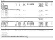
Page 217.4 Physical and Operational Specifications7.4.1 SHPF Pump SpecificationsModel No. HP Voltage Amps Pipe Size Carton Weight Overall Length 'A'SHPF.75 .75 208-230/115 6.0-5.6/11.2 2-2½" 43 lbs. 31 7 /8"SHPF1.0 1.0 208-230/115 7.8-7.4/14.8 2-2½" 45 lbs. 32¼"SHPF1.5 1.5 208-230 9.6-8.8 2-2½" 50 lbs. 32 5 /8"SHPF2.0 2.0 208-230 11.0-10.0 2-2½" 57 lbs. 33 1 /8"SHPF3.0 3.0 208-230 15.0-13.6 2½-3" 68 lbs. 33 1 /8"7.4.2 SHPM Pump SpecificationsModel No. HP Voltage Amps Pipe Size Carton Weight Overall Length 'A'SHPM1.0 1.0 208-230/115 6.0-5.6/11.2 2-2½" 43 lbs. 31 7 /8"SHPM1.5 1.5 208-230/115 7.8-7.4/14.8 2-2½" 45 lbs. 32¼"SHPM2.0 2.0 208-230 9.6-8.8 2-2½" 50 lbs. 32 5 /8"SHPM2.5 2.5 208-230 11.0-10.0 2-2½" 57 lbs. 33 1 /8"SHPM2.0-2 2.0 230 10.0/3.5 2-2½" 57 lbs. 32 5 /8"SHPM2.5-2 2.5 230 11.0/4.0 2-2½" 64 lbs. 33 1 /8"11 3 / 8" 16 1 / 8"'A'15¼"10 3 / 8"10 3 / 8"9"Bolt Holes,Center to Center14¾"Front Edge of Union to Centerof Bolt HolesNOTE When installing pump, leave a minimum of two feet(2 ft) of clearance above the pump for removal ofstrainer basket.
Page 227.5 Replacement Motor GuidePump ModelSHP Replacement Motor GuideA.O Smith /CenturyPump ModelA.O Smith/CenturySHPF .75 B661 N/A N/ASHPF 1.0 B841 SHPM 1.0 B863SESHPF 1.5 B842 SHPM 1.5 B864SESHPF 2.0 B843 SHPM 2.0 B865SESHPF 3.0 B844 SHPM 2.5 B866SESHPM 2.0 2SPD B983SHPM 2.5 2SPD B984
NOTESPage 23
LIMITED WARRANTYThank you for purchasing Jandy ® pool and spa products. Jandy <strong>Pool</strong> Products, Inc. warrants all parts to be freefrom manufacturing defects in materials and workmanship for a period of one year from the date of retailpurchase, with the following exceptions:• AquaLink ® RS units installed with Jandy ® Surge Protection Kits will be covered for two years.• NeverLube ® valves are warranted for the life of pool and/or spa on which they were originally installed.• AquaPure TM Electronic Chlorine Generator Electrolytic Cells carry a 5 year limited warranty on a prorated basis.This warranty is limited to the first retail purchaser, is not transferable, and does not apply to products that havebeen moved from their original installation sites. The liability of Jandy <strong>Pool</strong> Products, Inc. shall not exceed therepair or replacement of defective parts and does not include any costs for labor to remove and reinstall thedefective part, transportation to or from the factory, and any other materials required to make the repair. Thiswarranty does not cover failures or malfunctions resulting from the following:1. Failure to properly install, operate or maintain the product(s) in accordance with our published Installation,Operation and Maintenance Manuals provided with the product(s).2. The workmanship of any installer of the product(s).3. Not maintaining a proper chemical balance in your pool and/or spa [pH level between 7.2 and 7.8, TotalAlkalinity (TA) between 80 to 120 ppm, Total Dissolved Solids (TDS) less than 2000 not including salt ppm].4. Abuse, alteration, accident, fire, flood, lightning, rodents, insects, negligence or acts of God.5. Scaling, freezing, or other conditions causing inadequate water circulation.6. Operating the product(s) at water flow rates outside the published minimum and maximum specifications.7. Use of non-factory authorized parts or accessories in conjunction with the product(s).8. Chemical contamination of combustion air or improper use of sanitizing chemicals, such as introducingsanitizing chemicals upstream of the heater and cleaner hose or through the skimmer.9. Overheating; incorrect wire runs; improper electrical supply; collateral damage caused by failure of O-Rings,DE grids, or cartridge elements; or damage caused by running the pump with insufficient quantities of water.LIMITATION OF LIABILITY:This is the only warranty given by Jandy <strong>Pool</strong> Products, Inc. No one is authorized to make any other warrantieson behalf of Jandy <strong>Pool</strong> Products, Inc. THIS WARRANTY IS IN LIEU OF ALL OTHER WARRANTIES,EXPRESSED OR IMPLIED, INCLUDING BUT NOT LIMITED TO ANY IMPLIED WARRANTIES OF FITNESSFOR A PARTICULAR PURPOSE AND MERCHANTABILITY. JANDY POOL PRODUCTS, INC. EXPRESSLYDISCLAIMS AND EXCLUDES ANY LIABILITY FOR CONSEQUENTIAL, INCIDENTAL, INDIRECT ORPUNITIVE DAMAGES FOR BREACH OF ANY EXPRESSED OR IMPLIED WARRANTY. This warranty givesyou specific legal rights. You may also have other rights which vary by state or province.WARRANTY CLAIMS:For prompt warranty consideration, contact your dealer and provide the following information: proof of purchase,model number, serial number and date of installation. The installer will contact the factory for instructionsregarding the claim and to determine the location of the nearest designated service center. If the dealer is notavailable, you can locate a service center in your area by visiting www.jandy.com or by calling our technicalsupport department at (707) 776-8200 extension 260. All returned parts must have a Returned MaterialAuthorization number to be evaluated under the terms of this warranty.H0573800BCONFORMS TO UL 1081CERTIFIED TO CSA C22.2 NO 108Jandy <strong>Pool</strong> Products, Inc.6000 Condor Drive • Moorpark, CA USA 93021 • 707.776.8200 • Fax 707.763.7785Litho in U.S.A. © Jandy <strong>Pool</strong> Products, Inc. 0607