bm 302 / bm 402 bs 302 / bs 402 bd402 user's manual - Frederiksen
bm 302 / bm 402 bs 302 / bs 402 bd402 user's manual - Frederiksen
bm 302 / bm 402 bs 302 / bs 402 bd402 user's manual - Frederiksen
- No tags were found...

Create successful ePaper yourself
Turn your PDF publications into a flip-book with our unique Google optimized e-Paper software.
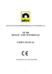
NÜVE SANAY MALZEMELER MALAT VETCARET A..BM <strong>302</strong> / BM <strong>402</strong>BS <strong>302</strong> / BS <strong>402</strong>BD<strong>402</strong>WATER BATHSUSER’S MANUAL
1. INTRODUCTION1.1. Use And FunctionBM <strong>302</strong> / BM <strong>402</strong> series general purpose water baths and BS <strong>302</strong>, BS <strong>402</strong> and BD <strong>402</strong>series refrigerated water baths are designed to carry out many applications in industrialand research laboratory environments.The water bathes consistently provide good temperature control, temperature uniformityand stability between +5°C above the ambient temperature and 80°C for BM series,between 0°C and +80°C for BS series and between –30°C and +40°C for BD <strong>402</strong>.The water baths consist of a heater, a stainless steel tank, a pump (1 pump is standardfor BM and BS series, 2 pumps are standard for BD <strong>402</strong>) and a control unit.The heater is placed on the bottom surface of the tank.The cooling function is obtained by the evaporator placed inside the stainless steel tankfor BS and BD series water baths.The powerful circulation pump provides a<strong>bs</strong>olutely homogenous temperature distributionin the tank, the second circulation pump for BD <strong>402</strong> can be used to regulate thetemperature of other equipment outside the water bath.The microprocessor controlled system ensures reliable and accurate temperature control.It also provides easy and comfortable programming.Programmable alarm limits assure safe working conditions.Do not operate the instrument for purposes other than main purpose.The instrument is only to be used by authorised people after the user’s <strong>manual</strong> hasbeen read carefully. Only technical personnel can handle the product in case of afailure.The BM, BS and BD series water baths are manufactured according to thefollowing standardsEN 61010-1, EN 50081-13
2. TECHNICAL SPECIFICATIONS2.1. Technical Specifications TableBM <strong>302</strong> BM <strong>402</strong> BS <strong>302</strong> BS <strong>402</strong> BD <strong>402</strong>Temperature Range Ambient Temp / 80 ° C 0ºC / 80ºC 0ºC /80ºC -30ºC/40ºCTemperature Sensor Fe-Const Pt – 100Control SystemProgrammable MicroprocessorTemperature Setand Display Activity0.1° CTemperature Variation at 37° C
3. INSTALLATION PROCEDURE3.1. Lifting And TransportAll lifting and transport must be carried out using proper handling equipment. The waterbath must be supported from underneath and never turned over.3.2. UnpackingRemove the packing cardboard box and the second nylon packing around the waterbath. The below written are provided with the equipment, please check them; User’s Manual Power cableCheck that no damage has occurred during transport,3.3. Environmental ConditionsPlease pay special attention to the followings, Indoor use only Room temperature from 5°C to 40 ° C Humidity level % 80 up to 22° C Maximum height 2000 m. The maximum performance is obtained between 15 °C and 25 ° C.3.4. Mains SupplyThe water baths require 230 V, 50 / 60 Hz.Please make sure that the supplied mains matches the required power ratings.Always plug the water baths to correctly grounded sockets.A supply fitted with a circuit breaker should be used for protection against indirectcontact in case of a isolation fault.3.5. PositioningLift the water bath underneath and carry it carefully to its place.Balance the water bath on the four pedestals. If necessary, adjust the height of thepedestals.6
Check the followings, The proposed site is suitable for users, The operator can follow up the water bath even he deals with something else. The water bath does not occupy the utilisation space of others or does not damagethem. There is enough space from the cooling unit ventilation. Leave at least 20cm on theright side of the refrigerated water baths. Leave at least 20 cm. Free space between the equipment and wall.3.6. Prior To Operation3.6.1. Filling in distilled water / liquid• Fill the tank with distilled water / liquid which will not freeze at the set temperature andput the samples and add distilled water / liquid until the maximum line MAX (seediagram below). UNDESIRED PROBLEMS OCCUR IF YOU FILL LIQUID UP TOTHE POINTS LOWER OR UPPER THAN THE MAX LINE.• Please add distilled water/liquid if the distilled water / liquid level drops below the MAXline during the operation.• Make sure that the filled liquid is not flammable or explosive at the operationtemperature.• 50 % distilled water and 50 % antifreeze mixture can be used 0°C and under 0°Coperations.MAX liquid level3.6.2. Important PointsPlug the instrument in to a grounded socket.Check the followings,• Liquids are not heated in sealed containers,• The boiling point of the samples are higher than the set temperature.• The freezing points of the samples are lower than the set the temperature.• The liquids which may expand during heating do not overflow from their containers,• The set temperature does not destroy the structure of the samples,• The vapor and gases which are generated during the operation are not harmful tohuman health or flammable or explosive,• Make sure that the samples do not overflow from their containers when heated.• Plug the power cable into a grounded socket.Note: Never use explosive, flammable, acidic or toxic liquids. Read carefully thefunctions of the control panel.7
4. OPERATING PRINCIPLES4.1. Switching OnPush the On/Off switch.See that the microprocessor control system activates.Set the values and start the operation.4.2. Display And Control Panel3167851112249101314181519171620 21 221. Temperature DisplayThis display shows,a) The temperature of the liquid inside the tank during the operation and the standby.b) The temperature and alarm set values during programming.c) The temperature and alarm set values during the control of set values.d) EoFF message in case of electrical interruption.e) Error codes in case of failure.f ) “ nuVE ” when the instrument is powered on.8
2. Heating Signal LEDThis LED flashes during the heating process.3. Cooling Signal LEDThis LED flashes during the cooling process.THERE IS NO COOLING SIGNAL LED ON THE CONTROL PANEL OF BM<strong>302</strong> / BM<strong>402</strong>4. Alarm Signal LEDAlarm signal LED flashes continuously if the temperature exceeds the factory set alarmlimits and in case of any failure detected by microprocessor control system.5. Time DisplayThis display shows :• The time set value during programming.• The elapsed time during the operation.• “Hold” during programming and the operation when the timer off is selected.• “Cont” during the control of set values.• The time set value during the control of the set values.• The repetition number if the Timer-2 is selected. (available for only nine-stepprogrammable systems)• The type of main PCB when the instrument is powered on.6. Timer-Off LEDThe “Timer-Off” should be selected to operate the water bath at hold position. The “Hold”is shown at the Time Display and this LED remains on until the program is stopped<strong>manual</strong>ly by using the STOP key.7. Timer - 1 LEDIf the Timer-1 option is selected, the timer counts up the time after the temperature hasreached the lower value of alarm limit. When the program finishes, the water bath turnsto stand-by position and the Timer - 1 LED flashes until the STOP key is pushed or thewater bath is switched off.8. Timer - 2 LEDAVAILABLE FOR ONLY NINE-STEP PROGRAMMABLE SYSTEMSIf the timer - 2 is selected, this LED turns on and the timer starts to count up the timewhen the program is started. At the end of the program, if the stop button is not pushedthe same program starts again and is repeated 20 times. At the end of the 20 threpetition, the Timer - 2 LED flashes and the instrument turns to the stand-by position.9
9. Program No DisplayNine - step programmable systems also have nine program memories.This display shows :• The number of the program which is operating.• The number of the program during programming.• The number of the program during the control of set values.• The first letter of thermocouple type as “ F “ ( for BM <strong>302</strong> / BM <strong>402</strong> ) or “ P “ for(BS<strong>302</strong> / BS <strong>402</strong> / BD <strong>402</strong> ) when the water bath is switched on.Note : For the single-step programmable systems, this display always shows “ 1 “.10. Step No DisplayThis display shows :• The number of the step which is operating.• The number of the step during programming.• The number of the step to be checked during the control of the set values.• The last letter of temperature sensor type as “E“( for BM <strong>302</strong> / BM <strong>402</strong> ) or “t“(BS <strong>302</strong>/ BS<strong>402</strong> / BD <strong>402</strong> ) when the water bath is powered on.Note : For the single-step programmable systems, this display always shows “p“.11. Program No KeyAVAILABLE FOR ONLY NINE-STEP PROGRAMMABLE SYSTEMSThis key is used :• To set the number of the program during programming.• To call the program to be operated or checked.The program number is increased by pressing the PROG NO key.12. Set Mode Key And LEDThe programming process is started by pushing this key. The LED turns on when the keyis pushed.The LED turns off when the TIMER MODE key is pressed and the set value is saved inthe memory.10
13. Timer Mode Key And LEDThe TIMER MODE key is pushed to select the type of timer.The LED turns on when the key is pushed. Push the Value Increase key to change thetype of timer.The related LEDs of timer type will turn on during the selection. The LED turns off whenthe STEP NO or STOP key is pushed and the set value is saved in the memory.14. Step No KeyAVAILABLE FOR ONLY NINE-STEP PROGRAMMABLE SYSTEMSThis key is used :• To set the number of the steps during programming• To call a step to be checked.The step number is increased by pressing the STEP NO key.15. Value Increase KeyThis key is used to increase the set values in the related display.Every push results in one unit increase. To rapidly increase the values, push the keycontinuously.16. Temp. Set Key And LEDThis key is used to set the required temperature of the program. The LED turns on whenthe key is pushed.To set the temperature value, push the TEMP SET key, then enter the requiredtemperature value by using the VALUE INCREASE or VALUE DECREASE keys .The LED turns off when the TIME SET key is pushed and the set value is saved in thememory.17. Time Set Key And LEDThis key is used to set the required time of the program. The TIME SET key is pushed toset the time.The LED turns on when the key is pushed. Use the VALUE INCREASE and VALUEDECREASE keys to adjust the time.The LED turns off when the ALARM SET key is pushed and the set value is saved in thememory.11
18. Alarm Set Key And LEDThis key is used to set the required alarm limits of the program.The Alarm Set key is pushed to set the alarm limits. The LED turns on when the key ispushed.The VALUE INCREASE and VALUE DECREASE are used to adjust the limits.The LED turns off when the STOP key is pushed and the set value is saved in thememory.19. Value Decrease KeyThis key is used to decrease the set values in the related display.Every push results in one unit decrease. To rapidly decrease of the values, push the keycontinuously.20. Start - 1 Key And LEDThe program can be started to run by pushing START–1 key. The LED of this key is onduring the operation and turn off when the program is completed.If the program is started with START-1 key, it is not cancelled by any electricityinterruption and keeps running.21. Start - 2 Key And LEDThe program can be started to run by pushing START-2 key.The LED of this key turns on during the operation and turns off after the completion of theprogram.If the program is started with START-2 key, the program may be cancelled by a electricityinterruption as described below :a) If the measured temperature stays within the programmed alarm limits following theinterruption, the program keeps running.b) If the measured temperature exceeds the programmed alarm limits following theinterruption, the EoFF occurs. The operation of the program is cancelled, the” EoFF”error code and the liquid temperature inside the tank is shown on Temperature Displaymomentarily and sequentially and the user is warned by the audible alarm. The waterbath turns back to stand-by position. To cancel the alarm, the program should be restartedor the STOP key should be pushed.12
c) If the measured temperature exceeds the factory set alarm limits after the interruption,the EoFF position occurs. The operation is cancelled, the “EoFF” error code is shownon the Temperature Display continuously and the user is warned by an audible alarm.The instrument turns to stand-by position. The STOP key should be pushed to stop thealarm and re-start the water bath.22. Stop Key And LEDThe STOP key is used to :• Validate the parameters and save them in the memory during programming.• Stop the running program <strong>manual</strong>ly.• Cancel the alarm.13
4.3. Programming SummaryProgramming Of Single Step Systemsno Steps of programming °C display TIME display1Press the button Water temperature in the tank SEt234Press the button Water temperature in the tank 00.00 timer-1 LED is onPress this button to choose TIMER-1 or TIMER OFF.Press this button to validate the entered value.5Press the button40.0 for BM <strong>302</strong> / <strong>402</strong> – BS <strong>302</strong> / <strong>402</strong>,0 for BD <strong>402</strong>00.00 or Hold6 Press these buttons to set the required temperature value( for BM <strong>302</strong> / <strong>402</strong> between ambient temperature +5°C and 80°C,for BS <strong>302</strong> / <strong>402</strong> between 0°C and 80°C,for BD <strong>402</strong> between -30°C and 40°C. )7Press the button Water temperature in the tank 00.00 or Hold89Press these buttons to set the required time value( 100 hours + hold position )If the "Timer Off" is selected , there is no need to enter any time valuePress the button 000.5 00.00 or Hold10Press these buttons to set the required alarm limit values. (between 0°C and 5°C)11Press this button to validate the entered values12orPress this button to start the programNote: At the 3th step if "TIMER OFF" is selected , Hold appeares on TIME display,“TIMER-1” is selected 00.00 appeares on TIME display.14
Multiple Step Programmingno Steps of programming °C display TIME display1Press this button to choose the program no2Press this button to choose the step no3Press the button Water temperature in the tank SEt456Press the button Water temperature in the tank 00.00 timer-1 LED is onPress the button to choose TIMER-1, TIMER-2 or TIMER OFFPress this button to validate the entered values7Press the button40.0 for BM <strong>302</strong> / <strong>402</strong> – BS <strong>302</strong> / <strong>402</strong>,0 for BD <strong>402</strong>00.00 or Hold8 Press these buttons to set the required temperature value( for BM <strong>302</strong> / <strong>402</strong> between ambient temperature +5°C and 80°C,for BS <strong>302</strong> / <strong>402</strong> between 0°C and 80°C,for BD <strong>402</strong> between -30°C and 40°C. )9Press the button Water temperature in the tank 00.00 or Hold1011Press these buttons to set the required time value( 100 hours + hold position )If the "Timer Off" is selected , there is no need to enter any time valuePress the button 000.5 00.00 or Hold12Press these buttons to set the required alarm limit values. (between 0°C and 5°C)1314Press this button to validate the entered valuesPress this button increase step no and repeat the (7), (8), (9), (10), (11), (12), (13), (14) numberedsteps to values for 9 programs15
15Press the button to increase program no and repeat between (2) and (15) numbered steps to valuesfor 9 programs16orPress this button to start the programNote:• According to programming summary table, at the 5 th step if "TIMER OFF" is selected,Hold appeares on the TIME display, if “TIMER1” or “TIMER-2” is selected 00.00appeares on the TIME display.• If “TIMER OFF“ position is selected, the program operates only the first steptemperature value until the program is stopped <strong>manual</strong>ly.• Push the VALUE INCREASE key continuously for 5 seconds to see the set valueswhile the water bath is running. First “Cont“, and then “Set“ are shown on the TimeDisplay. Release the key when “Set” appears. The set values will be shown on therelated displays and the LEDs of the related keys turn on sequentially. This cycle isrepeated twice.• To control the parameters for nine step of water baths push the STEP NO key duringcontrolling.• To control the parameters for other programs of instrument push the STEP NO keyduring controlling.4.4. Completion Of The Operation• See that the program is over.ATTENTION!! PLEASE BE AWARE OF THE LIQUID AMOUNT IN THE TANKDURING LONG OPERATIONS. PROTECT THE WATER BATH AGAINST THEFAILURES CAUSED BY THE LACK OF LIQUID.• Take the samples out. Be careful while handling the samples after the operation asthey can be hot.• Wipe the tank surface if needed after the tank has been completely emptied andwhen it is cold enough.• You may leave the bath at stand-by or switch it off.16
5. PERIODIC MAINTENANCE AND CLEANING5.1. Periodic MaintenancePlease add distilled water/liquid if the distilled water / liquid level drops below the MAXline during the operation.The water bath does not require any periodical maintenance which should be carried outby the operator. Please contact for your servicing and preventative maintenancerequirements.5.2. CleaningAfter unplugging the equipment and the equipment is at the room temperature, wipedown the tank surface to remove any undesirable effects of the operation, for examplespillage.For the external body, you may use a piece of cloth. Mild detergant use is recommendedto remove difficult dust and dirt.Protect your tank against rust coming from outside.Please be aware of the undesirable effects of the chemicals and be careful whileapplying them.6. TROUBLESHOOTING6.1. General TroubleshootingThe water bath fails to operate, check the followings,• The On/Off switch is on,• The plug is plugged-in properly,• The plug is not defective,• The mains supply is present.• Fuses are sound,• The installation of the plug is not defective,The water bath does not heat, check the followings,• The program is started.The water bath does not cool, check the followings,• The water pump operates,• The ambient temperature does not exceed 20 ± 5°C limits.17
6.2. Errors Recognised By The Microprocessor Control SystemIn case of failure during an operation, below written codes are shown onTemperature Display and the alarm sounds.Err 1 : Thermocouple ends are broken.Err 2 : There is an electronic fault.Err 3 : The measured temperature value exceeds the limits of measurement range.Err 4 : The thermocouple ends are connected in reverse or a 5°C difference has occuredduring the operation due to a heating / cooling failure.Err 6 : Timer-1 (or TIMER-2) is selected but no time value is set for the time.EoFF: This error code appears if START-2 has been chosen and any probable power cutcauses the temperature inside the liquid to go beyond the alarm limits.In case of any error, the program is stopped automatically and immediately.18
7. ELECTRICAL CIRCUIT DIAGRAMSBM <strong>302</strong>1. Mains supply connection clamp2. Main PCB phase feeder clamp3. Main PCB neutral feeder clamp4. Fuses5. EMC Filter6. ON / Off switch7. Fe-Const thermocouple (+) end clamp8. Fe-Const thermocouple (-) end clamp10. Heater relay outlet clamp (+)11. Heater relay outlet clamp (-)16. Circulation pump17. Heater18. SSR19. Main PCB20. Display and keyboard21. Fe-const19
BM <strong>402</strong>1. Mains supply connection clamp2. Main PCB phase feeder clamp3. Main PCB neutral feeder clamp4. Fuses5. EMC Filter6. ON / Off switch7. Fe-Const thermocouple (+) end clamp8. Fe-Const thermocouple (-) end clamp10. Heater relay outlet clamp (+)11. Heater relay outlet clamp (-)16. Circulation pump17. Heater18. SSR19. Main PCB20. Display and keyboard21. Fe-const20
BS <strong>302</strong>1. Mains supply connection clamp2. Main PCB phase feeder clamp3. Main PCB neutral feeder clamp4. Fuses5. EMC Filter6. ON / Off switch7-8-9. Pt – 100 end clamp10. Heater relay outlet clamp (+)11. Heater relay outlet clamp (-)12. Cooling relay outlet clamp (+)13. Cooling relay outlet clamp (-)16. Circulation pump17. Compressor18. Condanser cooling fan19. Heater20. Main PCB21. Display and keyboard22. SSR (heating)23. SSR (cooling)21
BS <strong>402</strong>1. Mains supply connection clamp2. Main PCB phase clamp3. Main PCB neutral clamp4. Fuses5. EMC filter6. On / Off switch7. Temperature sensor (Pt-100) clamp10. Main PCB heating relay (+) outlet11. Main PCB heating relay (-) outlet12. Main PCB cooling relay (+) outlet13. Main PCB cooling relay (-) outlet16. Water pump17. Compressor18. Condenser cooling fan motor19. Heater20. Main PCB21. Display PCB22. Pt - 10023. SSR (heating)24. SSR (cooling unit)22
BD <strong>402</strong>1. Mains supply connection clamp2. Main PCB phase clamp3. Main PCB neutral clamp4. Fuses5. On / Off switch6. Water pump7-8-9. Temperature sensor (Pt-100) clamp10. Main PCB heating relay (+) outlet11. Main PCB heating relay (-) outlet12. Main PCB cooling relay (+) outlet13. Main PCB cooling relay (-) outlet16. Compressor17. Condenser cooling fan motor18. Gas solenoid valve19. Heater20. Main PCB21. Display PCB22. Pt - 10023. SSR (heating)24. SSR (cooling unit)25. External water pump23