AP 418(S) - til india
AP 418(S) - til india
AP 418(S) - til india
- No tags were found...

Create successful ePaper yourself
Turn your PDF publications into a flip-book with our unique Google optimized e-Paper software.
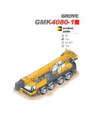
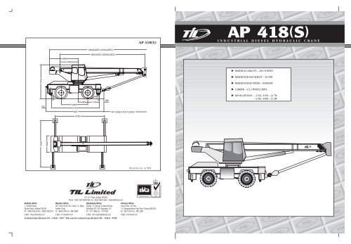
<strong>AP</strong> <strong>418</strong>(S)10060(3SEC)/9760(2SEC)8800(3SEC)/8500(2SEC)28981830343052124 026604760960 114524 038656674671(3SEC)/4371(2SEC)476055002500Dimensions in MM517, B.T. Road, Kolkata 700 058Phone : 2553 1352/1393/1882, Fax : 2553 2546 E-Mail : mktkmt@<strong>til</strong><strong>india</strong>.comEN 29001/ISO 9001/BS 5750<strong>AP</strong>PROVED BY BVQIKolkata Office Mumbai Office Sahibabad Office Chennai Office1, Taratolla Road 307, Centre Point, M.V. Road, J.V. Nagar Plot No. 11, Site No. 4 Industrial Area Jhaver Plaza, 7th floorGarden Reach, Kolkata-700 024 Andheri (East) Sahibabad 201 010, Ghaziabad, U.P. 1-A, Nungambakkam High Road, Chennai 600 034Ph : 2469-3732-36 Fax : 2469-2143/3731 Ph : 6643 0192 Fax : 6643 0904 Ph : 2777 0945 Fax : 2770 365 Ph : 2827 0723 Fax : 2827 9681E-Mail : mhg-er@<strong>til</strong><strong>india</strong>.com E-Mail : <strong>til</strong>_bby@vsnl.net E-Mail : shb-mhgmktg@<strong>til</strong><strong>india</strong>.com E-Mail : <strong>til</strong>chn@vsnl.netTechnical Specification TIL / <strong>418</strong>(S) / 0407. This cancels technical specification TIL / <strong>418</strong>(S) / 0598.NATIONALACCREDITATIONOF CERTIFICATIONBODIES
SUPERSTRUCTURE SPECIFICATIONCARRIER SPECIFICATIONSuperstructureFrameFabricated from high tensile steel plates andsections. Mechanical superstructure lock.Boom Derricking Single double-acting hydraulic ram mounted onSystemlarge diameter bushes. Fitted with hydrauliclock and counterbalance valve to prevent ramcollapse in event of hydraulic failure, andprovide positively controlled derricking out.Boom Angle Max. 76°, Min. (–)2°.Derricking Speed Max. to min. radius 45 secs. (unladen)Slew SystemSlew BrakeSlew SpeedSlew RingHoist SystemHoist BrakeLine SpeedTelescopingBoomSAFETY SYSTEMSafe LoadIndicatorMotion CutEquipmentGear type hydraulic motor driving a pinionthrough double reduction gear unit. Pinionmeshes with internally cut slew ring 360°smooth and continuous rotation on either side.Spring applied hydraulically released multi-platebrake.Limited to 2.0 rpm (unladen) for controlledoperation.Internal rack slew ring grease packed andsealed for long lifeGear type hydraulic motor driving hoistbarrel via reduction gear unit. Fitted withcounterbalance valve for controlled loweringof load. 13 mm dia non-spin hoist rope.Spring applied hydraulically released multi-platebrake.Top Layer 65m/min. (unladen)Fabricated from high tensile steel plates withinternal and external weld, adjustable & easilyreplaceable nylon wear pads. Hydraulic lockand counterbalance valve.8.80 m to 21.20 m centres 3 Section, fullypowered, fully synchronised boom to ensureproportional telescoping of boom sectionsunder single position control.Provides radius and hook load indication withvisual indication of approach to overload andvisual and audible indication of overloadcondition.Operated by the Safe Load Indicator, cutsderricking out, telescoping out and hoist motionwhen overload condition is reached. Additional tovisual and audible indication in operator's cab.Limit SwitchBoom Marker LightOperator’s CabCrane ControlsTravel ControlsInstrumentationOPTIONAL EQUIPMENTPendant overhoist limit switch at boom headand/or lattice extension.Mounted on superstructure totally enclosed,steel construction, full vision cab. Lockabledoor, interior light and horn. Ergonomicallydesigned cab and control layout with adjustableseat.Individual levers for independent orsimultaneous operation of crane motions,electric rocker switch for control of hydraulicoutriggers.Steering wheel operates orbitrol unit to controlthe Front axle. Steering column adjustable foroptimum driving/operating position. Gearshiftmounted on steering column. Service andparking brake controls.Gauges for engine oil pressure, engine coolanttemperature, brake air pressure, enginehourmeter and voltmeter. Warning lights foralternator, low air pressure, parking brake anddirection indicator.Telescopic Boom 8.50m to 14.70m centres 2 Section, fullypowered by means of single double-actinghydraulic ram.Lattice Extension 8.0 m centres swing around easy erected latticeboom extension to give maximum combinationof 29.20 m.Flood LightFitted to head of boom root section, or boomhead when reeling drum fitted.Carrier FrameOutriggersEngineTransmissionFuel TankHydraulicSystemHydraulic TankAXLESFront(Drive & Steer)RearBRAKESServiceParkingWheels andTyresElectricalEquipmentHeavy duty welded steel structure with integraloutrigger housings.Four hydraulically operated “graded” outriggerbeams with vertical hydraulic jacks fitted withlock valves. Vertical jacks fitted with removablestowable outrigger feet. Outrigger controlslocated in operator's cab. Independent controlof all outriggers with individual beam and jackoperation.Suitable water-cooled diesel engine developingadequate horsepower.Engine mounted full powershift with 4 forward& 3 reverse speeds.Capacity 164 litres.Gear type hydraulic pumps driven direct frompower-take-off mounted on torque convertor.Hydraulic overload valve protects the systemagainst excessive hydraulic oil pressure. Oilcooler maintains safe operating temperature ofhydraulic system.Capacity 200 litresSolidly mounted to carrier frame.Mounted on leaf spring and axle lock providedfor free-on-wheel duty.Foot operated compressed air over hydraulicbrake on front axle and pneumatic brake onrear axle.Fail safe spring operated pneumatically releasedtransmission brake.14.00 X 20 X 22 PR single pneumatic tyres onpressed steel discs fitted to both axles.24 V starting and lighting including 2 dippingheadlights, sidelights, rear and stop lights,flashing direction indicator.Tool BoxTurningCircle DiaAxle Loading(3-sec Boom)15m. (Outer Kerb)Front- 10.2 tonnesRear - 10.0 tonnesOPTIONAL EQUIPMENTTowing hook To rear of carrier.Spare wheel and tyreSpark arrestorMan carrying basketFire extinguisherTechnical Specification TIL / <strong>418</strong>(S) / 0407. This cancels technical specification TIL / <strong>418</strong>(S) / 0598. Technical Specification TIL / <strong>418</strong>(S) / 0407. This cancels technical specification TIL / <strong>418</strong>(S) / 0598.
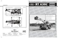
HEIGHT OF LIFT — 8.8M – 21.2M BOOM3 SEC BOOMHEIGHT OF LIFT — 8.5M – 14.7M BOOM2 SEC BOOMRANGE DIAGRAM (UNLADEN BOOM)RANGE DIAGRAM (UNLADEN BOOM)0.20mMulti-fall block(main boom)2.23m0.38m2.23mTwo-fall block(lattice extension)36343230280.20mMulti-fall block(main boom)2.23m0.38m2.23mTwo-fall block(lattice extension)28262422262075°70°65°8.8M BOOM60°55°11.5M BOOM50°14.5M BOOM17.5M BOOM45°40°21.2M BOOM + 8.0M LATTICE21.2M BOOM20.0M BOOM35°30°25°20°15°10°5°24222018161412108642Hook height (m)75°70°65°8.5M BOOM60°11.5M BOOM55°50°14.7M BOOM14.7M BOOM + 8.0M LATTICE45°40°35°30°25°20°15°10°5°18161412108642Hook height (m)0 2 4 6 8 10 12 14 16 18 20 22 24 26Radius (m)0280 2 4 6 8 10 12 14 16 18 20 22Radius (m)024Note : The above heights of lift are for multi-fall hookblocks on main boom and single-fall on lattice extension. Add 0.46 m if single-fallblock is used in place of multi-fall or deduct 0.46 m if multi-fall is used in place of single-fall.Hookblock capacities and weights – TonnesNo. of Falls 8 7 6 5 4 3 2 1Permissible Load 20.00 18.15 16.20 14.26 11.53 8.73 5.87 2.95Wt of Hookblock 0.20 0.20 0.20 0.20 0.20 0.20 0.10 0.09Note : The above heights of lift are for multi-fall hookblocks on main boom and single-fall on lattice extension. Add 0.46 m if single-fallblock is used in place of multi-fall or deduct 0.46 m if multi-fall is used in place of single-fall.Hookblock capacities and weights – TonnesNo. of Falls 8 7 6 5 4 3 2 1Permissible Load 20.00 18.15 16.20 14.26 11.53 8.73 5.87 2.95Wt of Hookblock 0.20 0.20 0.20 0.20 0.20 0.20 0.10 0.09Technical Specification TIL / <strong>418</strong>(S) / 0407. This cancels technical specification TIL / <strong>418</strong>(S) / 0598.Technical Specification TIL / <strong>418</strong>(S) / 0407. This cancels technical specification TIL / <strong>418</strong>(S) / 0598.
LIFTING C<strong>AP</strong>ACITIES – 2 SECTION BOOM – 85% RATINGMAXIMUM C<strong>AP</strong>ACITY 20 TONNESRated lifting capacities in tonnesLIFTING C<strong>AP</strong>ACITIES – 3 SECTION BOOM – 85% RATINGMAXIMUM C<strong>AP</strong>ACITY 20 TONNESRated lifting capacities in tonnesLifting Capacities on Outriggers - 360°Radius(m)8.5 m to 14.7 m boomplus 8.0m latticeextensionRadiusLaden(m) Load BoomAngle5.00 4.50 75.06.00 4.00 72.07.00 3.80 70.08.00 3.50 67.010.00 3.10 62.012.00 2.75 56.014.00 2.40 49.516.00 2.15 42.018.00 1.85 33.520.00 1.30 22.0Total Length -22.70 mBoom angles in degreesBoom Length (m)8.50 8.50 11.50Basic to toBoom 11.50 14.702.50 20.003.00 18.15 16.60 12.353.50 15.95 15.95 11.804.00 13.95 13.95 11.304.50 12.30 12.30 10.905.00 10.70 10.70 10.456.00 8.35 8.35 8.357.00 7.05 7.058.00 5.80 5.8010.00 4.4012.00 3.30Lifting Capacities onrubber; Tyres : 14.00 x 20x 22 PRRadius 5 Km/Hr Static(m) Over Over 360°Front Slew3.00 8.55a 8.00a3.50 7.55a 6.85a4.00 6.63a 5.80a4.50 5.48a 4.98a5.00 4.62a 4.32a6.00 3.40a 3.31a7.00 2.78b 2.76b8.00 2.19b 2.17b10.00 1.52c 1.49c12.00 1.00c 0.98cMax. allowable boom lengtha = 8.50 m, b = 11.50 m, c = 14.70 m.Important Notes1 All rated loads have been tested toand meet minimum requirementsof IS 4573-1982 – Specification forPower Driven Mobile Cranes anddo not exceed 85% of the tippingload on outriggers (85% of thetipping load on rubber) asdetermined by SAE J765 OCT80Crane Stability Test Code.2 Capacities above thick line arebased on factors other thanstability, hence crane tippingshould not be taken as sole guideto capacity limitation.3 Capacities shown in duty chartshould not be derricked below 12degrees boom angle.4 The weight of hookblock, slingsand all similar load handlingdevices must be added to weightof load.5 Capacities quoted are based onfreely suspended loads through 360deg. slew arc with outriggers fullyextended and vertical jacks downso that tyres are clear off the groundwith machine level on firm, uniformlysupporting surfaces or whenoperating free-on-wheels withmachine standing on firm, level,uniformly supporting surface andtyres inflated to correct pressure.6 Angle based capacities aredetermined by Laden Boom Anglegiven and not by radius. Radiiquoted refer to fully extendedboom only.7 Over front capacities must only belifted within a max. 2.5° on eitherside of crane centre line whenoperating “free-on-wheels”.8 Practical safe working loads aredependent on supporting surface,wind and other factors affectingstability, hazardous surrounding,experience of personnel, handlingof load, all of which to beconsidered.9 If lattice extn. is fitted in operatingposition main boom capacitiesmust be reduced by 0.76 tonne.10 When lattice extn. is fitted boommust be fully retracted for boomangles less than those specified.Lifting Capacities on Outriggers - 360°Radius(m)8.8 m to 21.2 m centrestele boom plus 8.0 mlattice extensionRadiusCapacity Laden(m)Over 360° BoomSlew Angle8.00 1.30 73.510.00 1.20 69.512.00 1.10 65.514.00 0.95 61.516.00 0.85 57.018.00 0.75 52.020.00 0.65 47.022.00 0.60 41.024.00 0.55 34.026.00 0.50 25.5Total Length -29.20 mBoom angles in degreesBoom Length (m)8.80 8.80 11.50 14.50 17.50 20.00Basic to to to to toBoom 11.50 14.50 17.50 20.00 21.202.50 20.003.00 18.15 13.65 13.353.50 15.70 13.65 12.95 8.754.00 13.30 13.30 12.45 8.454.50 11.75 11.75 11.75 8.25 6.505.00 10.20 10.20 10.20 7.95 6.30 5.206.00 8.05 8.05 8.05 7.40 5.95 4.957.00 7.15 7.15 6.90 5.60 4.708.00 5.95 5.95 5.95 5.30 4.5010.00 4.10 4.10 4.10 4.0012.00 3.20 3.20 3.20 3.2014.00 2.55 2.55 2.5516.00 2.00 2.0018.00 1.55Lifting Capacities onrubber; Tyres : 14.00 x 20x 22 PR5 Km/Hr StaticRadius(m)Over Over360°Front Slew3.00 8.25a 7.50a3.50 7.20a 6.45a4.00 6.40a 5.40a4.50 5.50a 4.55a5.00 4.55a 3.80a6.00 3.30a 2.80a7.00 2.70b 2.30b8.00 2.10b 1.70b10.00 1.40c 1.05c12.00 0.90c 0.50cMax. allowable boom lengtha = 8.80 m, b = 11.5 m,c = 14.50 m.Important Notes1 All rated loads have been tested toand meet minimum requirementsof IS 4573-1982 – Specification forPower Driven Mobile Cranes anddo not exceed 85% of the tippingload on outriggers (85% of thetipping load on rubber) asdetermined by SAE J765 OCT80Crane Stability Test Code.2 Capacities above thick line arebased on factors other thanstability, hence crane tippingshould not be taken as sole guideto capacity limitation.3 Capacities shown in duty chartshould not be derricked below 12degrees boom angle.4 The weight of hookblock, slingsand all similar load handlingdevices must be added to weightof load.5 Capacities quoted are based onfreely suspended loads through 360deg. slew arc with outriggers fullyextended and vertical jacks down sothat tyres are clear off the groundwith machine level on firm, uniformlysupporting surfaces or whenoperating free-on-wheels withmachine standing on firm, level,uniformly supporting surface andtyres inflated to correct pressure.6 Angle based capacities aredetermined by Laden Boom Anglegiven and not by radius. Radiiquoted refer to fully extendedboom only.7 Over front capacities must only belifted within a max. 2.5° on eitherside of crane centre line whenoperating “free-on-wheels”.8 Practical safe working loads aredependent on supporting surface,wind and other factors affectingstability, hazardous surrounding,experience of personnel, handlingof load, all of which to beconsidered.9 If lattice extn. is fitted in operatingposition main boom capacitiesmust be reduced by 0.76 tonne.10 When lattice extn. is fitted boommust be fully retracted for boomangles less than those specified.Technical Specification TIL / <strong>418</strong>(S) / 0407. This cancels technical specification TIL / <strong>418</strong>(S) / 0598.Technical Specification TIL / <strong>418</strong>(S) / 0407. This cancels technical specification TIL / <strong>418</strong>(S) / 0598.