+ SPECIALIST COMPLETIONS - Zenith Oilfield Technology Ltd
+ SPECIALIST COMPLETIONS - Zenith Oilfield Technology Ltd
+ SPECIALIST COMPLETIONS - Zenith Oilfield Technology Ltd
- No tags were found...

Create successful ePaper yourself
Turn your PDF publications into a flip-book with our unique Google optimized e-Paper software.
+ <strong>SPECIALIST</strong> <strong>COMPLETIONS</strong>GENERIC & BESPOKE SYSTEM DESIGNEach <strong>Zenith</strong> specialist completion system is designed to suit the specificrequirements of the operator, based on their well parameters andproduction objectives. Systems include unique features which address problems inherentin alternative equipment, addressing the following constraints that can occur with standardESP deployment:» Reduce downtime and lifetime intervention costs» Increase draw-down in constrained well geometries» Improve zone management and contribution: two wells in oneZENITH
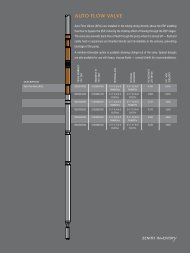
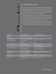
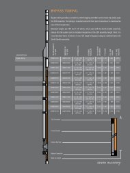
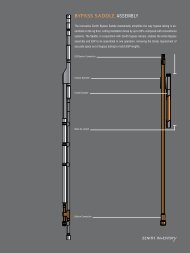
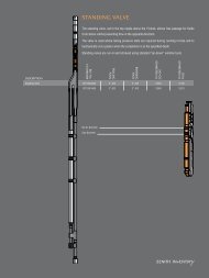
<strong>SPECIALIST</strong> COMPLETION SYSTEMSProduction from wells with a single ESP canbe limited by factors including the amountof horsepower attainable downhole, themaximum available ESP flow rate, highworkover costs, casing corrosion considerationsand limited control over productionzones. <strong>Zenith</strong> specialise in engineeringmultiple ESP completions which overcomethese constraints.CASING PROTECTION ESP SYSTEMSFor wells with casing integrity issues and corrosive fluids (fig. 1)The ESP system is housed in a pod which is stabbed into a lower packer. The pod and packerisolate the upper casing from the well fluid, protecting it from corrosive well fluids. Thepod enables the ESP to produce from below the packer by routing well fluid directly into theintake of the pump via the sealed pod unit. The pod has a penetrator system incorporated inthe pod hanger to allow the ESP cable to exit through a pressure-tight connection. Multiplepods may be deployed to provide redundancy in the event of ESP failure.PARALLEL ESP SYSTEMSFor wells that have high productivity indexes and therefore high potential rates (fig. 2)1.Pod AssemblyAuto Flow ValveThe parallel system uses two electrical submersible pumps to maximise flow rate where asingle ESP would not be capable of handling the well potential rate due to casing size, pumprate or power supply constraints. Production from two ESPs is combined at the Y-blockin the upper ESP bypass assembly. The bypass assembly suspends the lower ESP on itsbypass tubing.Each ESP can produce to the surface independently at a reduced rate in the event that apump should prematurely fail. This allows continued production, albeit at a lower rate, untilworkover is feasible.Upper ESP AssemblyDUAL BACK-UP ESP SYSTEMSFor wells with high workover costs or difficult access (fig. 2)In the event of an ESP failure, a back-up ESP already deployed in the well can be immediatelyturned on to maintain production. The second ESP is suspended below the upper ESPwith a bypass assembly. The bypass tubing provides a production path for the lower ESP.Normally the upper ESP is run first to prevent temperature effecting the backup systemrunlife. The lower ESP can be appropriately sized to accommodate changes in well performancesuch as decreasing reservoir pressure or increasing water cut.Replace the Y-block with the <strong>Zenith</strong> Auto Flow-Through tool for automatic switchingbetween upper and lower ESPs. The Auto Flow-Through also prevents circulation fromupper to lower ESP and vice-versa, and protects the pumps from descending solids onshut-down.E-Series SensorPackerDUAL BOOST ESP SYSTEMSFor wells that have lower productivity index values and require a large draw-down toovercome high back-pressure (fig. 3)Two ESPs are combined in series, sharing the number of stages and required horsepower.Pods are used to configure two ESPs in series, the lower ESP boosting the intake pressureof the ESP above it. The configuration enables two smaller ESPs to perform the job wherea single large ESP would normally be infeasible due to casing size, horsepower or shaftstrength limitations.If a single pump will not produce to surface then a third ESP can be included in the completionas a redundancy measure for the failed pump. The <strong>Zenith</strong> Auto Flow Valve ensures thatthe lower pumps can be run without having to produce through the upper pump stages. Thevalve opens and closes automatically depending on which ESP is running.
2. 3.4.Y-Block / Auto Flow-ThroughPod AssemblyY-Block / Flow Crossover AssemblySwivel Nipple AssemblySwivel Nipple AssemblyAuto Flow ValveAuto Flow ValveDischarge Pressure AssemblyCable Support Clampc/w cable clip for MLE cableCable Support Clampc/w cable clip for MLE cableUpper ESP AssemblyUpper ESP AssemblyUpper ESP AssemblyBypass TubingE-Series SensorPump SupportBypass TubingE-Series SensorCable PenetratorE-Series SensorPump SupportRotary Offset AssemblyPod AssemblyAuto Flow ValveAuto Flow ValveDischarge Pressure AssemblyESP Centraliser ClampLower ESP AssemblyLower ESP AssemblyLower ESP AssemblyE-Series SensorE-Series SensorE-Series Sensor
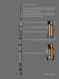
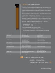
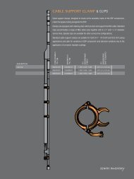
<strong>SPECIALIST</strong> COMPLETION SYSTEMS (Cont.)<strong>Zenith</strong> have the engineering know-how tomake certain the completion will integratecorrectly with your ESPs. Our team haveextensive experience in ensuring the completiondesign is fit-for-purpose to meet yourproduction requirements.BESPOKE SYSTEMSOne of <strong>Zenith</strong>’s keystrengths is our ability todesign bespoke completionsystems to your specificrequirements.<strong>Zenith</strong>’s design director is a recognisedworld leader in ESP completion design;responsible for the industry introduction ofthe highly successful bypass and dual ESPsystems with approximately 3,000 of hissystems installed to date worldwide.DUAL ZONE ESP SYSTEMSFor multiple zone wells that require control of zonal contribution (fig. 4)Dual zone completions enable production from multiple zone wells. A dedicated ESP foreach zone gives independent control of draw-down. This allows improved zone management,prevents cross-flow between zones, allows improved water management and enablesindividual production well tests on each zone independently. If used effectively duringfield planning, these systems can decrease the number of wells required to be drilled.Dual zone systems are available in two configurations:Commingling SystemsCombines production from dedicated ESPs for upper and lower zonesThe lower ESP is housed in a sealed pod which is stabbed into a permanent packer thatisolates the upper and lower zones. Production from the lower zone is produced by theESP inside the pod. The upper ESP is installed above the pod using a bypass system. Thelower zone is produced via the bypass tubing and its production commingled with productionfrom the upper zone at the Y-block. Zones can be produced either simultaneously orindependently by running upper, lower, or both ESPs. Cross-flow between zones duringproduction shut-down can be prevented, and well tests of individual zones can be carriedout to provide improved well testing. This is achieved by running each ESP individuallythereby producing only the relevant zone for testing.Dual Concentric SystemsDedicated ESPs for upper and lower zones that isolate zone contribution to surface productionfacilitiesThe dual concentric system is similar to the commingled system described above but producesthe zones independently to surface using concentric production strings. This systemis particularly useful where complete isolation of production zones is a requirement. Fluidfrom the lower zone is produced to surface through a flow crossover tool which routes thefluid through the inner production tubing string. Fluid from the upper pump flows throughthe inside of the flow crossover tool and to the surface through the annulus between the innerand outer production strings. The two separate production strings exit the well througha concentric well head that allows flow through two separate production flow lines.DUAL BACK-UP WITH WIRELINE ACCESSFor wells with high workover costs or difficult access that require wireline access below(fig. 5)In the event of an ESP failure, a back-up ESP already deployed in the well can be immediatelyturned on to maintain production. The second ESP is suspended below the upper ESPwith a bypass assembly. The bypass tubing provides a production path for the lower ESPwith the third leg allowing wireline access for logging operations.Normally the upper ESP is run first to prevent temperature effecting the backup systemrunlife. The lower ESP can be appropriately sized to accommodate changes in well performancesuch as decreasing reservoir pressure or increasing water cut.
5.Tri-ToolSwivel Nipple Assembly<strong>SPECIALIST</strong> COMPLETION SYSTEM BENEFITSCASING PROTECTION ESP SYSTEMSProtect casing from corrosive well fluidsProtect ESPs during deploymentCable Support Clampc/w cable clip for MLE cableBypass TubingPARALLEL ESP SYSTEMSAchieve maximum flow ratesDUAL BACK-UP ESP SYSTEMSMinimise lifetime intervention costsUpper ESP AssemblyReduce downtime and deferred production when ESP failure occursDUAL BOOST ESP SYSTEMSAchieve maximum draw-downBypass TubingE-Series SensorPump SupportDUAL ZONE ESP SYSTEMSEnables simultaneous production of incompatible fluids from separate zonesPrevents water coning, maintaining well asset viabilityAllows simultaneous production and injection through a single well boreReduces topside separator capacity requirementDrill fewer wellsTest zones independentlyReduced deferment: the second ESP provides back-up should one system failDUAL BACK-UP WITH WIRELINE ACCESSBack-up ESP with access below the pumpsLower ESP AssemblyE-Series SensorRe-entry GuideZENITH
ZKG-0605-005_11 — April 2008 — © <strong>Zenith</strong> — zenithoilfield.com<strong>Zenith</strong> <strong>Oilfield</strong> <strong>Technology</strong> patents pending & protected worldwide