Operation instruction - Asennustuotteet
Operation instruction - Asennustuotteet
Operation instruction - Asennustuotteet
- No tags were found...

Create successful ePaper yourself
Turn your PDF publications into a flip-book with our unique Google optimized e-Paper software.
kgABB i-bus ® KNXBinary Inputs BE/SProduct Manual
ABB i-bus ® KNXContentsContentsPage1 General 51.1 Using the product manual.....................................................................51.1.1 Structure of the product manual.........................................................51.1.2 Notes..................................................................................................61.2 Product and functional overview...........................................................71.2.1 Short overview ...................................................................................82 Device technology 92.1 Binary Input with manual operation,4-fold, 230 V AC/DC, MDRC ................................................................92.1.1 Technical data....................................................................................92.1.2 Connection schematic BE/S 4.230.2.1 ............................................112.1.3 Dimensional drawing BE/S 4.230.2.1 ..............................................122.2 Binary input with manual operation,4-fold, contact scanning, MDRC.........................................................132.2.1 Technical data..................................................................................132.2.2 Connection schematic BE/S 4.20.2.1 ..............................................152.2.3 Dimensional drawing BE/S 4.20.2.1 ................................................162.3 Binary Input with manual operation,8-fold, 230 V AC/DC, MDRC ..............................................................172.3.1 Technical data..................................................................................172.3.2 Connection schematic BE/S 8.230.2.1 ............................................192.3.3 Dimensional drawing BE/S 8.230.2.1 ..............................................202.4 Binary Input with manual operation,8-fold, contact scanning, MDRC.........................................................212.4.1 Technical data..................................................................................212.4.2 Connection schematic BE/S 8.20.2.1 ..............................................232.4.3 Dimensional drawing BE/S 8.20.2.1 ................................................242.5 Assembly and installation ...................................................................252.6 Manual operation ................................................................................272.6.1 Display elements..............................................................................282.6.2 Operating controls............................................................................293 Commissioning 313.1 Overview.............................................................................................313.1.1 Conversion .......................................................................................323.1.1.1 Procedure ......................................................................................333.1.2 Copy and exchange parameter settings ..........................................343.1.2.1 Procedure ......................................................................................353.1.2.2 Copy/Exchange channels dialog ...................................................363.2 Parameters .........................................................................................383.2.1 Parameter window Device information ............................................393.2.2 Parameter window General .............................................................403.2.3 Parameter window Manual ..............................................................433.2.4 Parameter window Push button for manual operation.....................463.2.5 Parameter window Input LED ..........................................................473.2.6 Communication objects General......................................................483.2.7 Parameter window Enable Inputs A…X...........................................50© 2011 ABB STOTZ-KONTAKT GmbH i
ABB i-bus ® KNXGeneral1 GeneralAll ABB i-bus ® KNX devices are as easy and intuitive to operate as possible.Accordingly, a clear and comfortable intelligent building installation can beeasily realized.The Binary Inputs BE/S fulfil the individual needs both in functional buildingsas well as in the private residential sector.1.1 Using theproduct manualThis manual provides you with detailed technical information relating to theBinary Inputs, their installation and programming.The application of the device is described using examples.This manual is divided into the following sections:Chapter 1GeneralChapter 2Device technologyChapter 3CommissioningChapter 4Planning and applicationChapter AAppendix1.1.1 Structure of theproduct manualAll parameters are described in chapter 3.NoteIn this product manual, both 4-fold and 8-fold Binary Inputs are described.These devices each have four or eight binary inputs. However, as thefunctions for all binary inputs are identical, only the functions of input Awill be described.Should the details in the product manual refer to all binary inputs, 4-foldcorresponds to inputs A…D and 8-fold corresponds to inputs A…H andthe designation inputs A…X is used.© 2011 ABB STOTZ-KONTAKT GmbH 5
ABB i-bus ® KNXGeneral1.1.2 NotesNotes and safety <strong>instruction</strong>s are represented as follows in this productmanual:NoteTips for usage and operationExamplesApplication examples, installation examples, programming examplesImportantThese safety <strong>instruction</strong>s are used as soon as there is danger of amalfunction without risk of damage or injury.CautionThese safety <strong>instruction</strong>s are used if there is a danger of damage withinappropriate use.DangerThese safety <strong>instruction</strong>s are used if there is a danger for life and limb withinappropriate use.DangerThese safety <strong>instruction</strong>s are used if there is a danger to life withinappropriate use.© 2011 ABB STOTZ-KONTAKT GmbH 6
ABB i-bus ® KNXGeneral1.2 Product andfunctional overviewThe binary inputs serve as interfaces for operation of KNX systems viaconventional buttons/switches or for coupling of binary signals (signalcontacts).The devices feature a push button for manual operation for each input. Inputstates can be simulated during manual operation, so that the conventionalpush buttons, switches or floating contacts do not need to be connected forcommissioning purposes.The inputs are modular installation devices with a module width of 2 and4 space units in Pro M design for installation in a distribution board. Theconnection to the ABB i-bus ® is established using the front side busconnection terminal. The assignment of the physical addresses as well asthe parameterization is carried out with Engineering Tool Software ETS3.NoteThe illustrations of the parameter windows in this manual correspond tothe ETS3 parameter windows. The application program is optimised forETS3.The processing of the binary signals is carried out in the correspondingapplication program• Binary 4f 23021/1.0, Binary 4f 2021/1.0,• Binary 8f 23021/1.0, Binary 8f 2021/1.0© 2011 ABB STOTZ-KONTAKT GmbH 7
ABB i-bus ® KNXGeneral1.2.1 Short overviewApplication possibilities BE/S 4.x.2.1 BE/S 8.x.2.1Inputs 4 8Switch sensor/Fault monitoring input • •Switch/Dim sensor • •Blind sensor • •Value/Forced operation • •Control scene • •Switching sequences • •Multiple operation • •Counter • •Parameterization options BE/S 4.x.2.1 BE/S 8.x.2.1Inputs 4 8Switching and dimming of lighting (also for1-button operation)<strong>Operation</strong> of shutters and blinds (also for 1-button operation)Sending of arbitrary values, e.g.temperature values• •• •• •Control and saving of light scenes • •<strong>Operation</strong> of different consumers byrepeated actuation<strong>Operation</strong> of several loads in a definedswitching sequence• •• •Counting from impulses and actuations • •Reading of floating contacts • •Each Binary Input of a device can assumeone of the functions described beforehand.• •© 2011 ABB STOTZ-KONTAKT GmbH 8
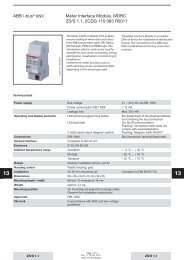
ABB i-bus ® KNXDevice technology2 Device technology2.1 Binary Input with manualoperation, 4-fold, 230 VAC/DC, MDRCBE/S 4.230.2.12CDC 071 010 F0010The 4-fold Binary Input BE/S 4.230.1 with manual operation is a railmounted device for installation in the distribution board. The device issuitable for reading out 10…230 V AC/DC signals.Inputs A and B are independent of inputs C and D.Buttons located on the front of the device can be used to manually simulatethe input state. The status of the inputs is displayed by yellow LEDs.The device is ready for operation after connecting the bus voltage.The Binary Input is parameterized via ETS. The connection to the KNXis implemented using the bus connection terminal on the front.2.1.1 Technical dataSupply Bus voltage 21…32 V ACCurrent consumption, busPower consumption, busLeakage loss, busMaximum 5 mAMaximum 100 mWMaximum 800 mW at AC operationMaximum 1.6 W at DC operationInputs Number 4Permitted voltage range U nInput current I nSignal level for 0 signalSignal level for 1 signalPermissible cable length0…265 V AC/DCMaximum 1 mA0…2 V AC/DC7…265 V AC/DCMaximum 100 m at 1.5 mm²Connections KNX Via bus connection terminalsInputsVia slotted head screw terminalsConnection terminals Screw terminals 0.2…2.5 mm² stranded0.2…4.0 mm² solidTightening torqueMaximum 0.6 NmOperating and display elements Button/LED Programming For assignment of the physical addressButton /LED For toggling between manualoperation/operation via ABB i-bus ® anddisplaysButton/LED(applies for all binary inputs, A…D)For switching and displayEnclosure IP 20 To EN 60 529Safety class II To EN 61 140© 2011 ABB STOTZ-KONTAKT GmbH 9
ABB i-bus ® KNXDevice technologyIsolation category Overvoltage category III to DIN EN 60 664-1Pollution degree 2 to EN 60 664-1KNX safety extra low voltageTemperature rangeSELV 24 V DC<strong>Operation</strong>StorageTransport-5 °C…+45 °C-25 °C…+55 °C-25 °C…+70 °CAmbient conditions Maximum air humidity 93 %, no condensation allowedDesign Modular installation device (MDRC) Modular installation device, Pro MDimensions 90 x 36 x 67.5 mm (H x W x D)Mounting width in space unitsMounting depth2 modules at 18 mm67.5 mmInstallation On 35 mm mounting rail To EN 60 715Mounting positionWeightHousing/colourAs required0.1 kgPlastic housing, greyApprovals KNX to EN 50 090-1, -2 CertificationCE markIn accordance with the EMC guideline andlow voltage guidelineDevice type Application program Maximum number ofcommunication objectsMaximum number ofgroup addressesMaximum number ofassociationsBE/S 4.230.2.1 Binary 4f 23021/…* 43 254 254* … = current version number of the application programNoteThe ETS and the current version of the device application program arerequired for programming.The current version of the application program is available for downloadon the Internet at www.abb.com/knx. After import it is available in the ETSunder ABB/Input/Binary input 4-fold.The device does not support the closing function of a KNX device in theETS. If you inhibit access to all devices of the project with a BCU code,it has no effect on this device. Data can still be read and programmed.© 2011 ABB STOTZ-KONTAKT GmbH 10
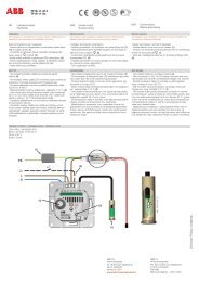
ABB i-bus ® KNXDevice technology2.1.2 Connection schematicBE/S 4.230.2.12CDC 072 157 F00092CDC 072 161 F0009Connection of AC voltageConnection of DC voltage1 Label carrier 2 Button Programming3 LED Programming 4 Bus connection terminal5 Button Manual operation 6 LED Manual operation7 Connection terminals 8 LED Binary input9 Button Binary inputImportantWhen connecting AC voltage, twoseparate RCD (earth-leakagecircuit breaker) circuits can beconnected to terminals 1, 2, 3 and4, 5, 6.ImportantCorrect polarity must be observedwhen the DC voltage is connected.If incorrectly connected, the inputcannot be read out and processed.ImportantUse of switch or a push-in inserts with N terminals, in conjunction with theBE/S 4.230.2.1 series Binary Inputs are absolutely necessary to ensuremalfunction free operation and sufficient illumination of glow lamps onilluminated switches or plug-in inserts.© 2011 ABB STOTZ-KONTAKT GmbH 11
ABB i-bus ® KNXDevice technology2.1.3 Dimensional drawingBE/S 4.230.2.12CDC 072 192 F0009© 2011 ABB STOTZ-KONTAKT GmbH 12
ABB i-bus ® KNXDevice technology2.2 Binary input withmanual operation,4-fold, contactscanning, MDRCBE/S 4.20.2.12CDC 071 009 F0010The 4-fold Binary Input BE/S 4.20.2.1 with manual operation is a railmounted device for installation in the distribution board. The device issuitable for reading floating contacts. The pulsed scanning voltage isgenerated internally.Buttons located on the front of the device can be used to manually simulatethe input state. The status of the inputs is displayed by yellow LEDs.The device is ready for operation after connecting the bus voltage.The Binary Input is parameterized via ETS. The connection to the KNXis implemented using the bus connection terminal on the front.2.2.1 Technical dataSupply Bus voltage 21…32 V DCCurrent consumption, busPower consumption, busLeakage loss, busMaximum 6 mAMaximum 130 mWMaximum 130 mWInputs Number 4Scanning voltage U nScanning current I nScanning current I n at switch onPermissible cable length35 V, pulsed0.1 mAMaximum 355 mAMaximum 100 m at 1.5 mm²Connections KNX Via bus connection terminalsInputsVia screw terminalsConnection terminals KNX Via bus connection terminalsInputsVia slotted head screw terminalsOperating and display elements Button/LED Programming For assignment of the physical addressButton /LED For toggling between manualoperation/operation via ABB i-bus ® anddisplaysButton/LED(applies for all binary inputs, A…D)For switching and displayEnclosure IP 20 To EN 60 529Safety class II To EN 61 140Isolation category Overvoltage category III to DIN EN 60 664-1Pollution degree 2 to EN 60 664-1KNX safety extra low voltageSELV 24 V DC© 2011 ABB STOTZ-KONTAKT GmbH 13
ABB i-bus ® KNXDevice technologyTemperature range<strong>Operation</strong>StorageTransport-5 °C…+45 °C-25 °C…+55 °C-25 °C…+70 °CAmbient conditions Maximum air humidity 93 %, no condensation allowedDesign Modular installation device (MDRC) Modular installation device, Pro MDimensions 90 x 36 x 67.5 mm (H x W x D)Mounting width in space unitsMounting depth2 modules at 18 mm67.5 mmInstallation On 35 mm mounting rail To EN 60 715Mounting positionWeightHousing/colourAs required0.1 kgPlastic housing, greyApprovals KNX to EN 50 090-1, -2 CertificationCE markIn accordance with the EMC guideline andlow voltage guidelineDevice type Application program Maximum number ofcommunication objectsMaximum number ofgroup addressesMaximum number ofassociationsBE/S 4.20.2.1 Binary 4f 2021/…* 43 254 254* … = current version number of the application programNoteThe ETS and the current version of the device application program arerequired for programming.The current version of the application program is available for downloadon the Internet at www.abb.com/knx. After import it is available in the ETSunder ABB/Input/Binary input 4-fold.The device does not support the closing function of a KNX device in theETS. If you inhibit access to all devices of the project with a BCU code,it has no effect on this device. Data can still be read and programmed.© 2011 ABB STOTZ-KONTAKT GmbH 14
ABB i-bus ® KNXDevice technology2.2.2 Connection schematicBE/S 4.20.2.12CDC 072 156 F00091 Label carrier 2 Button Programming3 LED Programming 4 Bus connection terminal5 Button Manual operation 6 LED Manual operation7 Connection terminals 8 LED Binary input9 Button Binary inputNoteAn external voltage connection to the Binary Input BE/S 4.20.2.1 is notpermitted.Terminals 3 and 4 are internally interconnected to one another.© 2011 ABB STOTZ-KONTAKT GmbH 15
ABB i-bus ® KNXDevice technology2.2.3 Dimensional drawingBE/S 4.20.2.12CDC 072 190 F0009© 2011 ABB STOTZ-KONTAKT GmbH 16
ABB i-bus ® KNXDevice technology2.3 Binary Input withmanual operation,8-fold, 230 V AC/DC,MDRCBE/S 8.230.2.12CDC 071 012 F0010The 8-fold Binary Input BE/S 8.230.2.1 with manual operation is a railmounted device for installation in the distribution board. The device issuitable for reading out 10…230 V AC/DC signals.Buttons located on the front of the device can be used to manually simulatethe input state. The status of the inputs is displayed by yellow LEDs.The device is ready for operation after connecting the bus voltage.The Binary Input is parameterized via ETS. The connection to the KNXis implemented using the bus connection terminal on the front.2.3.1 Technical dataSupply Bus voltage 21…32 V DCCurrent consumption, busPower consumption, busLeakage loss, busMaximum 6 mAMaximum 120 mWMaximum 1.5 W at AC operationMaximum 3.0 W at DC operationInputs Number 8 individualPermitted voltage range U nInput current I nSignal level for 0 signalSignal level for 1 signalPermissible cable length0…265 V AC/DCMaximum 1 mA0…2 V AC/DC7…265 V AC/DCMaximum 100 m at 1.5 mm²Connections KNX Via bus connection terminalsInputs Using universal head screw terminals (PZ 1)Connection terminalsScrew terminalFerrules without/with plastic sleevesTWIN ferrulesTightening torqueGridScrew terminals with universal head (PZ 1)0.2…4 mm² stranded, 2 x (0.2…2.5 mm²)0.2…6 mm² solid, 2 x (0.2…4 mm²)Without: 0.25…2.5 mm²With: 0.25…4 mm²0.5…2.5 mm²Contact pin length at least 10 mmMaximum 0.8 Nm6.35Operating and display elements Button/LED Programming For assignment of the physical addressButton /LED For toggling between manualoperation/operation via ABB i-bus ® anddisplaysButton/LED(applies for all binary inputs, A…H)For switching and display© 2011 ABB STOTZ-KONTAKT GmbH 17
ABB i-bus ® KNXDevice technologyEnclosure IP 20 To EN 60 529Safety class II To EN 61 140Isolation category Overvoltage category III to DIN EN 60 664-1Pollution degree 2 to EN 60 664-1KNX safety extra low voltageTemperature rangeSELV 24 V DC<strong>Operation</strong>StorageTransport-5 °C…+45 °C-25 °C…+55 °C-25 °C…+70 °CAmbient conditions Maximum air humidity 93 %, no condensation allowedDesign Modular installation device (MDRC) Modular installation device, Pro MDimensions 90 x 72 x 67.5 mm (H x W x D)Mounting width in space unitsMounting depth4 modules at 18 mm67.5 mmInstallation On 35 mm mounting rail To EN 60 715Mounting positionWeightHousing/colourAs required0.2 kgPlastic housing, greyApprovals KNX to EN 50 090-1, -2 CertificationCE markIn accordance with the EMC guideline andlow voltage guidelineDevice type Application program Maximum number ofcommunication objectsMaximum number ofgroup addressesMaximum number ofassociationsBE/S 8.230.2.1 Binary 8f 23021/…* 83 254 254* … = current version number of the application programNoteThe ETS and the current version of the device application program arerequired for programming.The current version of the application program is available for downloadon the Internet at www.abb.com/knx. After import it is available in the ETSunder ABB/Input/Binary input 8-fold.The device does not support the closing function of a KNX device in theETS. If you inhibit access to all devices of the project with a BCU code,it has no effect on this device. Data can still be read and programmed.© 2011 ABB STOTZ-KONTAKT GmbH 18
ABB i-bus ® KNXDevice technology2.3.2 Connection schematicBE/S 8.230.2.12CDC 072 159 F00092CDC 072 163 F0009Connection with AC voltageConnection with DC voltage1 Label carrier 2 Button Programming3 LED Programming 4 Bus connection terminal5 Button Manual operation 6 LED Manual operation7 Connection terminals 8 LED Binary input9 Button Binary inputImportantWhen connecting AC voltage, up toeight separate RCD (earth-leakagecircuit breaker) circuits can beconnected.ImportantCorrect polarity must be observedwhen the DC voltage is connected.If incorrectly connected, the inputcannot be read out and processed.ImportantUse of switch or a push-in inserts with N terminals, in conjunction with theBE/S 8.230.2.1 series Binary Inputs are absolutely necessary to ensuremalfunction free operation and sufficient illumination of glow lamps onilluminated switches or plug-in inserts.© 2011 ABB STOTZ-KONTAKT GmbH 19
ABB i-bus ® KNXDevice technology2.3.3 Dimensional drawingBE/S 8.230.2.12CDC 072 196 F0009© 2011 ABB STOTZ-KONTAKT GmbH 20
ABB i-bus ® KNXDevice technology2.4 Binary Input withmanual operation,8-fold, contactscanning, MDRCBE/S 8.20.2.12CDC 071 011 F0010The 8-fold Binary Input BE/S 8.20.2.1 with manual operation is a railmounted device for installation in the distribution board. The device issuitable for reading floating contacts. The pulsed scanning voltage isgenerated internally.Buttons located on the front of the device can be used to manually simulatethe input state. The status of the inputs is displayed by yellow LEDs.The device is ready for operation after connecting the bus voltage.The Binary Input is parameterized via ETS. The connection to the KNXis implemented using the bus connection terminal on the front.2.4.1 Technical dataSupply Bus voltage 21…32 V DCCurrent consumption, busPower consumption, busLeakage loss, busMaximum 7 mAMaximum 150 mWMaximum 150 mWInputs Number 8Scanning voltage U nScanning current I nScanning current I n at switch onPermissible cable length35 V, pulsed0.1 mAMaximum 355 mAMaximum 100 m at 1.5 mm²Connections KNX Via bus connection terminalsInputs Using universal head screw terminals (PZ 1)Connection terminalsScrew terminalFerrules without/with plastic sleevesTWIN ferrulesTightening torqueGridScrew terminals with universal head (PZ 1)0.2…4 mm² stranded, 2 x (0.2…2.5 mm²)0.2…6 mm² solid, 2 x (0.2…4 mm²)Without: 0.25…2.5 mm²With: 0.25…4 mm²0.5…2.5 mm²Contact pin length at least 10 mmMaximum 0.8 Nm6.35Operating and display elements Button/LED Programming For assignment of the physical addressButton /LED For toggling between manualoperation/operation via ABB i-bus ® anddisplaysButton/LED(applies for all binary inputs, A…H)For switching and display© 2011 ABB STOTZ-KONTAKT GmbH 21
ABB i-bus ® KNXDevice technologyEnclosure IP 20 To EN 60 529Safety class II To EN 61 140Isolation category Overvoltage category III to DIN EN 60 664-1Pollution degree 2 to EN 60 664-1KNX safety extra low voltageTemperature rangeSELV 24 V DC<strong>Operation</strong>StorageTransport-5 °C…+45 °C-25 °C…+55 °C-25 °C…+70 °CAmbient conditions Maximum air humidity 93 %, no condensation allowedDesign Modular installation device (MDRC) Modular installation device, Pro MDimensions 90 x 72 x 67.5 mm (H x W x D)Mounting width in space unitsMounting depth4 modules at 18 mm67.5 mmInstallation On 35 mm mounting rail To EN 60 715Mounting positionWeightHousing/colourAs required0.2 kgPlastic housing, greyApprovals KNX to EN 50 090-1, -2 CertificationCE markIn accordance with the EMC guideline andlow voltage guidelineDevice type Application program Maximum number ofcommunication objectsMaximum number ofgroup addressesMaximum number ofassociationsBE/S 8.20.2.1 Binary 8f 2021/…* 83 254 254* … = current version number of the application programNoteThe ETS and the current version of the device application program arerequired for programming.The current version of the application program is available for downloadon the Internet at www.abb.com/knx. After import it is available in the ETSunder ABB/Input/Binary input 8-fold.The device does not support the closing function of a KNX device in theETS. If you inhibit access to all devices of the project with a BCU code,it has no effect on this device. Data can still be read and programmed.© 2011 ABB STOTZ-KONTAKT GmbH 22
ABB i-bus ® KNXDevice technology2.4.2 Connection schematicBE/S 8.20.2.12CDC 072 158 F00091 Label carrier 2 Button Programming3 LED Programming 4 Bus connection terminal5 Button Manual operation 6 LED Manual operation7 Connection terminals 8 LED Binary input9 Button Binary inputNoteAn external voltage connection to the Binary Input BE/S 4.20.2.1 is notpermitted.Terminals 2, 4, 6, 8, 10, 12, 14 and 16 are internally interconnected to oneanother.© 2011 ABB STOTZ-KONTAKT GmbH 23
ABB i-bus ® KNXDevice technology2.4.3 Dimensional drawingBE/S 8.20.2.12CDC 072 194 F0009© 2011 ABB STOTZ-KONTAKT GmbH 24
ABB i-bus ® KNXDevice technology2.5 Assembly andinstallationThe Binary Input is a modular installation device for fast installation in thedistribution board on 35 mm mounting rails to EN 60 715.The mounting position can be selected as required.The connection to the bus is implemented using the supplied bus connectionterminal.The device is ready for operation after connection of the bus voltage and,if required, the auxiliary voltage.The terminal designation is located on the housing.Accessibility to the device for the purpose of operation, testing, visualinspection, maintenance and repair must be provided compliant toVDE 0100-520.Commissioning requirementsIn order to commission the device, a PC with Engineering Tool Software(ETS) and an interface, e.g. USB or IP are required.The installation and commissioning may only be carried out by qualifiedelectrical specialists. The appropriate norms, guidelines, regulations andspecifications of your country should be observed when planning and settingup electrical installations.Protect the device from damp, dirt and damage during transport, storage andoperation.Only operate the device within the specified technical data limits!The device should only be operated in an enclosed housing (distributionboard)!The voltage supply to the device must be switched off before mountingwork is performed.DangerIn order to avoid dangerous touch voltages, which originate throughfeedback from differing phase conductors, all-pole disconnection must beobserved when extending or modifying the electrical connections.Supplied stateThe device is supplied with the physical address 15.15.255.The application program is pre-installed. It is therefore only necessaryto load group addresses and parameters during commissioning.However, the complete application program can be reloaded ifrequired. The entire application program is loaded after a changeof the application program, after a discontinued download or afterdischarge of the device. The process takes significantly longer thanloading parameters and group addresses.© 2011 ABB STOTZ-KONTAKT GmbH 25
ABB i-bus ® KNXDevice technologyDownload behaviourDepending on the PC, which is used, the progress bar for the download maytake up to one and a half minutes, before it appears, due to the complexity ofthe device.Assignment of the physical addressThe assignment and programming of the physical address is carried out inthe ETS.The device features a programming button for assignment of the physicaldevice address. The red programming LED lights up, after the button hasbeen pushed. It switches off as soon as the ETS has assigned the physicaladdress or the programming button is pressed again.CleaningIf devices become dirty, they can be cleaned using a dry cloth or a clothdampened with a soapy solution. Corrosive agents or solutions should neverbe used.MaintenanceThe device is maintenance-free. No repairs should be carried out byunauthorised personnel if damage occurs, e.g. during transport and/orstorage.Foil keypadThe manual pushbuttons may not be operated with pointed or sharp-edgedobjects, e.g. screwdrivers or pens. This may damage the keypad.© 2011 ABB STOTZ-KONTAKT GmbH 26
ABB i-bus ® KNXDevice technology2.6 Manual operationFunction of manual operationAfter connection to the bus, the device is in KNX operation. The LED is off.All LEDs indicate the actual input state. The respective Buttons are nonfunctional.It is possible to switch between Manual operation and KNXoperation by pressing the button.Should Manual operation be activated, the current input states remain set.The inputs can only be operated via the foil keypad. If group addresses havebeen assigned, telegrams will be sent on the bus. Any signal changes fromthe installed system will not be considered. If Manual operation isdeactivated, switchover to KNX operation and the respective LED againindicates its current input state. The communication objects are updated andtelegrams are sent. The programmed input states thus set themselves.NoteIf button is released again before two seconds have elapsed, the LEDreverts to its old state and there is no reaction.If Manual operation is not enabled via the application program, there is noreaction and the device remains in the KNX operation. If it has beendisabled, LED is switched on or over, after it has flashed for threeseconds.NoteIf the input is disabled and the option yes is selected with parameterCyclic sending, the last state is still sent regardless of the block.Using the communication object Block (No. 10), the physical input as wellas the communication object Event 0/1 are disabled, but internal sendingcontinues, i.e. the input terminals are physically disconnected from theapplication program.The communication object Block (No.10) has no influence on manualoperation.© 2011 ABB STOTZ-KONTAKT GmbH 27
ABB i-bus ® KNXDevice technology2.6.1 Display elementsThe indicator LEDs are located on the front of the Binary Inputs, e.g. on theBE/S 8.20.2.1 eight LEDs Input X (X = A…H), one LED Manual operation:All Input X LEDs indicate the current input state. In KNX operation, the LEDis off.The behaviour of the display elements dependent on the operating states,KNX operation and Manual operation is described in the following table:LED KNX operation Manual operationInput A…XThe LED display is independent of the programming. Itcan be set separately for each Binary Input.• normal: Contact is closed => LED onContact is open => LED offThe LED display is independent of the programming. Itcan be set separately for each Binary Input.• normal: Contact is closed => LED onContact is open => LED off• Block:The LED cannot be changed andremains disabled.• Block:The LED cannot be changed andremains disabled.Manual operation• inverted: Contact is closed => LED offIn this way, the LED display can be adapted to theinput state for closed and opened contacts.For fault alarms, e.g. both normally closed andnormally opened contacts can be used.• Off: BE/S is in KNX operation• Flashes (for about 3 seconds): Changeover toManual operation.• Flashes continuously: Manual operation is softwareinhibitedvia KNX. The LED flashes until buttonis pressed. The LED switches off when released.• inverted: Contact is closed => LED offIn this way, the LED display can be adapted to theinput state for closed and opened contacts.For fault alarms, e.g. both normally closed andnormally opened contacts can be used.• Flashes (for about 3 seconds): Changeover to KNXoperation.• On: BE/S is in Manual operation.© 2011 ABB STOTZ-KONTAKT GmbH 28
ABB i-bus ® KNXDevice technology2.6.2 Operating controlsThe buttons for manual operation are located on the front of the BinaryInputs, e.g. on the BE/S 8.20.2.1, eight buttons for Input X (X = A…H),one button for Manual operation:The operating controls are enabled or disabled by button Manual operation. The button must be pushed for at least 1.5 seconds for this purpose.This prevents unintentional actuation of the operating controls.Switch on of manual operation:Press button until the yellow LED lights continuously.Switch off of manual operation:Press button until LED no longer lights.NoteUsing the communication object Block, the physical input as well as thecommunication object Event 0/1 are disabled, but internal sendingcontinues, i.e. the input terminals are physically disconnected from theapplication program.The communication object Block has no influence on manual operation.The status of the simulated input signal continues to be sent here.NoteManual operation can be inhibited via the KNX using communicationobject Enable/block manual operation. In this case, it is not possible tochangeover to manual operation using button Manual operation. Theblock can be removed by sending a telegram with the value 0 on thecommunication object Enable/block manual operation. The block is alsoremoved after a download and bus voltage recovery. The communicationobject again assumes the value 0.© 2011 ABB STOTZ-KONTAKT GmbH 29
ABB i-bus ® KNXDevice technologyThe behaviour of the operating elements dependent on the operating states,KNX operation and Manual operation, is described in the following table:Button KNX operation Manual operationManual operationInput A…X• Long button operation (about 3 Sec.): Switch toManual operation provided that Manual operation isnot blocked by a parameter setting.• Short button push: LED Manual operation flashesand switches off again. BE/S continues in KNXoperation.No reaction• Long button operation (about 3 Sec.): Changeoverto the KNX operation. The inputs are scanned again,and the input states are updated accordingly.Reset of Manual operation to KNX operation can occurwithin a programmed time depending on theparameterization.The behaviour of button Input A is dependent on theparameterization under Enable/block buttons:• Block: The binary input is disabled.• Switch:• Button:With every actuation, the statesof the input and the LED arechanged.Push the button=> Input closed => LED onRelease the button=> Input opened => LED offNoteBy pressing button , binary inputA is simulated.The display indicates the currentinput state. The parameterizedfeatures are executed.© 2011 ABB STOTZ-KONTAKT GmbH 30
ABB i-bus ® KNXCommissioning3 Commissioning3.1 OverviewThe application programs Binary 4f 23021/1.0, Binary 4f 2021/1.0, Binary 8f23021/1.0 and Binary 8f 2021/1.0 are available for the binary inputs.Programming requires ETS. A maximum of 10 communication objects perBinary Input, 254 group addresses and 254 associations can be linked.The following operating modes are available for each binary inputSwitch sensor/Faultmonitoring inputSwitch/Dim sensorBlind sensorValue/ForcedoperationControl sceneSwitching sequencesMultiple operationCounterFor scanning conventional inputs.Distinction between short/long operation and cyclical sending ofthe contact state is possible.Blocking of a binary input is possible.The operating mode can be used as fault monitoring input.Up to three communication objects can be programmed differentlyand can be sent on the KNX.For control/dimming of lighting via a 1 button and 2 buttonoperation.Start-stop dimming and stepwise dimming as well as switchingand dimming via a single push button are possible.For control/slat adjustment of a blind or a shutter in 1 buttonoperation and 2 button operation.Eight preset operating responses are possible in total.For sending of arbitrary values of different data types, e.g.temperature values.It is possible to send different values or data types after ashort/long operation. Activation/deactivation of the forcedoperation of actuators is also possible.For calling and storing the states of up to six actuator groups. Theactuator groups can be controlled via six individualcommunication objects.For the operation of several actuator groups in preset sequences.For triggering of different functions depending on the frequency ofactuation.Even a long actuation can be detected and a function triggered.For counting input pulses.Different data types can be set. An additional differential counterenables counting of daily values for example. Different count ratescan be set.The main and differential counters can be reset.NoteEach binary input of a device can be blocked separately by acommunication object.© 2011 ABB STOTZ-KONTAKT GmbH 31
ABB i-bus ® KNXCommissioning3.1.1 ConversionFor ABB i-bus ® KNX devices from ETS3 or higher, it is possible to assumethe parameter settings and group addresses from previous applicationprogram versions.Furthermore, conversion can be implemented to transfer the existingparametrization of a device to another device.NoteWhen the term “channels” is used in the ETS, inputs and/or outputs aremeant. In order to ensure that the ETS language generally applies for asmany ABB i-bus ® devices as possible, the word channels is used here.The following application programs can be completely converted:• Binary 4f 2021/1.0• Binary 4f 23021/1.0• Binary 8f 2021/1.0• Binary 8f 23021/1.0• Binary 4f 2021/1.1• Binary 4f 23021/1.1• Binary 8f 2021/1.1• Binary 8f 23021/1.1NoteIf the number of channels of the target device is larger than the number ofinputs/outputs of the source device, only the first inputs/outputs of thetarget device are written with the converted data of the source device.The remaining inputs/outputs retain the default values or are reset to thedefault values.Default values are set for newly added parameters after conversion.© 2011 ABB STOTZ-KONTAKT GmbH 32
ABB i-bus ® KNXCommissioning3.1.1.1 Procedure• Import the current VD3 file into ETS3 and add a product with the currentapplication program to the project.• After you have parameterized a device, you can transfer the settingsto a second device.• Right click on the product and select Convert in the context menu for thispurpose.• Then follow the <strong>instruction</strong>s of the Convert wizard.• Finally, exchange the physical address and delete the old device.Should you wish to only copy individual channels within a device, use thefunction Copy and exchange, page 33.© 2011 ABB STOTZ-KONTAKT GmbH 33
ABB i-bus ® KNXCommissioning3.1.2 Copy and exchangeparameter settingsParameterization of devices can take a lot of time depending on thecomplexity of the application program and the number of deviceinputs/outputs. To keep the commissioning work to the minimum possible,using the function Copy/Exchange channels, parameter settings of aninput/output can be copied or exchanged with freely selectableinputs/outputs. Optionally, the group addresses can be retained, copied ordeleted in the target input/output.NoteWhen the term “channels” is used in the ETS, inputs and/or outputs aremeant. In order to ensure that the ETS language generally applies for asmany ABB i-bus ® devices as possible, the word channels is used here.The copy function for inputs/outputs is particularly useful with devices havingthe same parameter settings for several outputs, inputs or groups.For example, lighting in a room is frequently controlled in an identicalmanner. In this case, the parameter settings from input/output X can becopied to all other inputs/outputs or to a special input/output of the device.Thus the parameters for this input/output must not be set separately, whichsignificantly shortens the commissioning time.The exchange of parameter settings is useful, e.g. should the inputs/outputsbe swapped when wiring the terminals. The parameter settings of theincorrectly wired inputs/outputs can be simply exchanged saving therequirement for time-consuming rewiring.© 2011 ABB STOTZ-KONTAKT GmbH 34
ABB i-bus ® KNXCommissioning3.1.2.1 Procedure• Import the application program into ETS and add a product with thecurrent application program to the project.• Click with the right mouse button on the product, whose inputs/outputsyou wish to copy or exchange, and select the context menuCopy/Exchange channels.Thereafter, undertake the required settings in the Copy/Exchange channelsdialog.© 2011 ABB STOTZ-KONTAKT GmbH 35
ABB i-bus ® KNXCommissioning3.1.2.2 Copy/Exchangechannels dialogAt the top right, you will see the source channel selection window formarking the source channel. Beside is located the selection window for thetarget channel or channels for marking the target channel or channels.Source channelWith the selection of the source channel, you define which parametersettings should be copied or exchanged. Only one source channel can beselected at a time.Target channelsWith the selection of the target channels, you define which channel/channelsare to assume the parameter settings of the source channel.• For the function Exchange, only one target output can be selected at atime.• For the function Copy, different target channels can be selectedsimultaneously. For this purpose, press the Ctrl key and mark therequired channels with the mouse cursor, e.g. channels B and C.With this button, you select all available target channels,e.g. A…C.Reset the selection of the target channels with this button.© 2011 ABB STOTZ-KONTAKT GmbH 36
ABB i-bus ® KNXCommissioningCopyThe following options can be selected before copying the parametersettings:• Leave the group addresses unchanged (if possible) in the target channel• Copy group addresses• Delete group addresses in the target channelWith this button, copy the settings of the source channel intothe target channel or channels.ExchangeThe following options can be selected before exchanging the parametersettings:• Retain group addresses• Exchange of group addresses• Deletion of group addressesWith this button, exchange the settings of the source channelwith the target channel.Confirm your selection with this button, and the windowcloses.Using this button, the window closes without accepting thechanges.© 2011 ABB STOTZ-KONTAKT GmbH 37
ABB i-bus ® KNXCommissioning3.2 ParametersThe parameterization of the binary inputs is implemented using theEngineering Tool Software ETS. The application program is available in theETS under ABB/Input/Binary input 4/8-fold.The following chapter describes the parameters of the binary input using theparameter window. The parameter window features a dynamic structure, sothat further parameters may be enabled depending on the parameterizationand the function.The default values of the parameters are underlined,e.g.:Options: yesnoNoteIn this product manual, both 4-fold and 8-fold Binary Inputs are described.These devices each have four or eight binary inputs. However, as thefunctions for all binary inputs are identical, only the functions of input A willbe described.Should the details in the product manual refer to all binary inputs, 4-foldcorresponds to inputs A…D and 8-fold corresponds to inputs A…H, andthe designation inputs A…X is used.© 2011 ABB STOTZ-KONTAKT GmbH 38
ABB i-bus ® KNXCommissioning3.2.1 Parameter windowDevice informationThis parameter window contains important information about the BE/S andthe respective application program.ImportantObserve the important notes in the device information.They differ for the different device variants.Here for example, the device information for the BE/S 8.20.2.1 is shown.NOTESThe button "Standard" re-establishesthe delivery status!< NOTEThe application programcan be downloadedfrom our websitewww.abb.com/knx.< NOTE© 2011 ABB STOTZ-KONTAKT GmbH 39
ABB i-bus ® KNXCommissioning3.2.2 Parameter windowGeneralHigher level parameters can be set in the General parameter window.Sending delay after busvoltage recovery in s [2…255]Options: 2…255Telegrams are only received during the send delay.However, the telegrams are not processed. No telegrams are sent on thebus.Telegrams are sent, after the send delay has been completed.If communication objects are read out via the bus during the send delay,e.g. from the visualisations, these requests are stored and if necessaryanswered, after the send delay has been completed.An initialisation time of about two seconds is included in the delay time.The initialisation time is the reaction time that the processor requires to befunctional.How does the device behave with bus voltage recovery?After bus voltage recovery, the device always waits for the send delaytime to elapse before sending telegrams on the bus.© 2011 ABB STOTZ-KONTAKT GmbH 40
ABB i-bus ® KNXCommissioningLimit number of telegramsOptions: noyesThe load on the bus generated by the device can be limited with thelimitation on the number of telegrams sent. This limit relates to all telegramssent by the device.• yes: The following parameters appear:Max. number of senttelegrams in s [1…255]Options: 1…20…255in periodOptions: 50 ms/100 ms…1 s…30 s/1 minThese parameters determine the number of telegrams, which can besent by the device within a period. The telegrams are sent as quicklyas possible at the start of a period.Send communication object “in operation”Options: nosend value 0 cyclicallysend value 1 cyclicallyThe in operation communication object indicates the presence of the deviceon the bus. This cyclic telegram can be monitored by an external device.If a telegram is not received, the device may be defective or the bus cable tothe transmitting device may be interrupted.• no: The communication object In operation is not enabled.• send value 0/1 cyclically: The communication object In <strong>Operation</strong> issent cyclically on the KNX.An additional parameter appears:Sending cycle time in s [1…65,535]Options: 1…60…65,535Here the time interval, at which the In operation communication objectcyclically sends a telegram, is set.NoteAfter bus voltage recovery, the communication object sends itsvalue after the set sending and switching delay.© 2011 ABB STOTZ-KONTAKT GmbH 41
ABB i-bus ® KNXCommissioningEnable communication object"Request status values" 1 bitOptions: noyes• yes: A 1 bit communication object Request status values is enabled.Via this communication object, all status messages can be requestedprovided that they have been parameterized with the option after a changeor request.With option yes, the following parameters appear:Recall with object valueOptions: 010 or 1• 0: Sending status messages is requested with the value 0.• 1: Sending status messages is requested with the value 1.• 0 or 1: Sending of the status messages is requested with thevalues 0 or 1.© 2011 ABB STOTZ-KONTAKT GmbH 42
ABB i-bus ® KNXCommissioning3.2.3 Parameter windowManualAll the settings for manual operation are made in this parameter window.Manual operationOptions: enable/disable via communication objectenableddisabledThis parameter defines if the switch over between the operating statesManual operation and KNX operation is enabled or disabled via the buttonon the device.• enable/disable via communication object: The communication objectEnable/block manual operation (No. 2) appears.Telegram value 0 = button enabled1 = button disabledNoteIn manual operation, the applied input states can be overwritten.NoteUsing the communication object Block (No. 10), the physical input as wellas the communication object Event 0/1 are disabled, but internal sendingcontinues, i.e. the input terminals are physically disconnected from theapplication program.The communication object Block (No.10) has no influence on manualoperation.© 2011 ABB STOTZ-KONTAKT GmbH 43
ABB i-bus ® KNXCommissioningReset manual operation to KNX operationOptions: noafter 1/3/10/30 minute(s)This parameter determines how long the Binary Input remains in the Manualoperation mode after pressing the button.• no: The Binary Input remains in Manual operation, until the button ispressed again.• after X minutes: The Binary Input remains in Manual operation after thelast button push, until either button is pushed again or theprogrammed time has timed out.Enable power saving mode(LEDs in KNX mode off)Options: noafter 1/3/10/30 minute(s)This parameter determines whether the yellow LEDs for manual operationin KNX mode should be switched off after a parameterized time.The device and the channels are still controlled via the bus; however,the current status of the channels is not displayed via the yellow LEDs.When any button is pressed, the power saving mode is interrupted and thestatus of the inputs is shown even if manual operation is inhibited. If no otherbutton is pressed, the power saving mode is reactivated after theparameterized time and the LEDs switch off.NoteAll options to reset a device, e.g. via a download, an ETS reset or busvoltage recovery are treated with the same priority in power saving mode.• no: LED display is activated.• after 1/3/10/30 minute(s): The power saving mode is activated after thetime parameterized here. The power saving mode is interrupted with thefollowing actions, and the status is displayed.• Switch-over to KNX mode• Interruption of power saving mode by pressing a button• Programming, download or ETS resetEnable communication object"Status man. operation" 1 bitOptions: noyes• yes: The communication object Status man. operation (No. 3) isenabled. An additional parameter appears:© 2011 ABB STOTZ-KONTAKT GmbH 44
ABB i-bus ® KNXCommissioningSend object valueOptions: no, update onlyafter a changeafter requestafter a change or request• no, update only: The status is updated but not sent.• after a change: The status is sent after a change.• after request: The status is sent after a request.• after a change or request: The status is sent after a changeor a request.For further information see: Manual operation, page 26© 2011 ABB STOTZ-KONTAKT GmbH 45
ABB i-bus ® KNXCommissioning3.2.4 Parameter windowPush button for manualoperationIn this parameter window, the binary inputs are enabled or blocked and theconfiguration (switch, button) is determined.Input AOptions:diasbleswitchpush buttonWith this parameter, input A can be disabled or enabled as a switch or pushbutton.• disable: The binary input is disabled.• switch: With every actuation, the states of the input and the LED arechanged.• push button: Press button => input closed, LED onRelease button => input opened, LED offNoteBy pressing button , binary input A is simulated.The display indicates the current input state. The parameterized featuresare executed.Input B…XThe operation of input A does not differ from the operation of inputs B…X.© 2011 ABB STOTZ-KONTAKT GmbH 46
ABB i-bus ® KNXCommissioning3.2.5 Parameter windowInput LEDThe settings for the LED of the binary input can be undertaken in thisparameter window.LED input AOptions: normaldisabledinvertedThis parameter defines whether the LED display is normal or inverted. It isset separately for each Binary Input.• normal: Contact is closed => signal present => LED onContact is open => no signal => LED off• disabled: The LED cannot be changed and remains disabled.• inverted: Contact is closed => signal present => LED offContact open => no signal => LED onIn this way, the LED display can be adapted to the input state for closed andopened contacts.For fault alarms, e.g. both normally closed and normally opened contactscan be used.© 2011 ABB STOTZ-KONTAKT GmbH 47
ABB i-bus ® KNXCommissioning3.2.6 Communication objectsGeneralNo. Function Object name Data type Flags0 In operation System 1 bitDPT 1.002C, R, TThe communication object is enabled if the parameter Send communication object"in operation" in the parameter window General has been selected with yes.In order to regularly monitor the presence of the device on the KNX, an in operationmonitoring telegram can be sent cyclically on the bus.As long as the communication object is activated, it sends a programmable in operationtelegram.1 Request status values General 1 bitDPT 1.017C, R, TIf a telegram with the value x (x = 0/1/0 or 1) is received in the communication object, allstatus objects are sent on the bus, as long as these have not been programmed with theoption after a change or request.The following function results for the option x = 1:Telegram value:1 = all status messages are sent, provided they areprogrammed with the option after a change or request.0 = no reaction© 2011 ABB STOTZ-KONTAKT GmbH 48
ABB i-bus ® KNXCommissioningNo. Function Object name Data type Flags2 Enable/block manualoperationManual operation1 bitDPT 1.003C, R, TManual operation is enabled or disabled via this communication object.NoteIf this communication object is assigned to a group address, manualoperation is disabled after each download, ETS reset or bus voltagerecovery.If the value 0 is in this communication object, then the binary input can be switched toManual operation using the button on the device.If this communication object has a 1, the Binary Input is in KNX operation.Telegram value: 0 = button enabled1 = button disabledNoteUsing the communication object Block (No. 10), the physical input as well asthe communication object Event 0/1 are disabled, but internal sendingcontinues, i.e. the input terminals are physically disconnected from theapplication program.The communication object Block (No.10) has no influence on manualoperation.3 Status man. operation Manual operation 1 bitDPT 1.003C, R, TOn this communication object, the binary input sends the information regarding whether it isin Manual operation or KNX operation.The status is sent after a change.Telegram value:0 = KNX operation1 = manual operation© 2011 ABB STOTZ-KONTAKT GmbH 49
ABB i-bus ® KNXCommissioning3.2.7 Parameter windowEnable Inputs A…XIn this parameter window, all the settings for Enabl Inputs A…X areundertaken.NoteIn the following, the setting possibilities of Inputs A…X are explained usinginput A as an example.The setting possibilities are identical for all inputs.Enable Input AOptions: noyes• yes: An additional parameter appears:Operating modeOptions: Switch sensor/Fault monitoring inputSwitch/Dim sensorBlind sensorValue/Forced operationControl sceneSwitching sequencesMultiple operationCounterThe operating mode of the input is defined with this parameter.The respective parameter window A: xxx also becomes visiblewith the selection of an operating mode.© 2011 ABB STOTZ-KONTAKT GmbH 50
ABB i-bus ® KNXCommissioningDesignation(40 characters)Options: - - - TEXT - - -With this parameter, it is possible to enter a text of up to 40 charactersin length for identification in the ETS.NoteThis entered text is used to assist in providing a quick and simpleoverview of the assignment and function of the inputs.The text is purely for informative purposes and has no further function.Inputs B…XNoteThe parameter descriptions should be taken from the description of inputA!© 2011 ABB STOTZ-KONTAKT GmbH 51
ABB i-bus ® KNXCommissioning3.2.8 Operating modeSwitch sensor/Faultmonitoring inputIn this chapter, you will find all descriptions for the parameter windowsand the corresponding communication objects for operating modeSwitch sensor/Fault monitoring input.NoteThe inputs B…X do not differ from input A.The descriptions of the parameter setting possibilities and the adjustablecommunication objects for the inputs B…X should be taken from thedescriptions from parameter window Enable Inputs A…X, page 50!© 2011 ABB STOTZ-KONTAKT GmbH 52
ABB i-bus ® KNXCommissioning3.2.8.1 Parameter windowA: Switch sensorIn this parameter window, all settings are undertaken for parameter windowA: Switch sensor. The explanations also apply for the Inputs B…X.This parameter window is visible if in parameter window Enable Inputs A…X,page 50, the option Switch sensor/Fault monitoring input has been selectedin parameter Input A.Enable communication object"Disable" 1 bitOptions: noyes• yes: The 1 bit Block communication object is enabled.The input can be enabled or disabled.NoteIf the input is disabled and the option yes is selected with parameterCyclic sending, the last state is still sent regardless of the block.Using the communication object Block (No. 10), the physical input as wellas the communication object Event 0/1 are disabled, but internal sendingcontinues, i.e. the input terminals are physically disconnected from theapplication program.The communication object Block (No.10) has no influence on manualoperation.© 2011 ABB STOTZ-KONTAKT GmbH 53
ABB i-bus ® KNXCommissioningEnable communication object"Event 0/1 started" 1 bitOptions: noyes• yes: The 1 bit communication object Event 0/1 started is enabled.As a result, the same events, such as those of the push button/switchconnected to the binary input, can also be triggered by the receipt of atelegram on the communication object Event 0/1 started. A set Minimumsignal time or Distinction between short and long operation is not takeninto consideration, i.e. the event is implemented immediately. Also referto the block diagram Switch sensor, page 139.NoteIf the input is disabled and the option yes is selected with parameterCyclic sending, the last state is still sent regardless of the block.Using the communication object Block (No. 10), the physical input as wellas the communication object Event 0/1 are disabled, but internal sendingcontinues, i.e. the input terminals are physically disconnected from theapplication program.The communication object Block (No.10) has no influence on manualoperation.Capacitive screeningOptions: up to 10 nF (standard)up to 20 nFup to 30 nFup to 40 nFThis parameter defines the degree of capacitive screening.Transmission errors can occur on extended cable lengths under certainconditions, e.g. in a 5 x 1.5 mm 2 cable, where two conductors are used as asignal line and one conductor is used for switching loads, it may result inmutual interference. If this proves to be the case in an installation, thesensitivity of the input is increased. It should be noted that the signalevaluation also slows down.Debounce timeOptions: 10/20/30/50/70/100/150 msDebouncing prevents unwanted multiple operations of the input,e.g. due to bouncing of the contact.© 2011 ABB STOTZ-KONTAKT GmbH 54
ABB i-bus ® KNXCommissioningWhat is the debounce time?If an edge is detected at an input, the input will react immediately tothis edge, e.g. by sending a telegram. At the same time, the durationof the debounce time T D starts. The signal on the input is notevaluated within the debounce time duration.Example: Debounce time of the input signal for a detected edge:After detection of an edge on the input, further edges are ignored forthe debounce time T D .Distinction between short andlong operationOptions: yesnoUsing this parameter, you set if the input differentiates between short andlong operation.• yes: After opening/closing of the contact, first of all it is necessary toascertain whether a short or long operation has occurred here. Onlythereafter will a possible reaction be triggered.The following drawing shows the function in detail:T L is the time duration from where a long operation is detected.© 2011 ABB STOTZ-KONTAKT GmbH 55
ABB i-bus ® KNXCommissioning3.2.8.1.1 ParameterDistinction betweenshort and longoperation – noIf the option no is selected with the parameter Distinction between short andlong operation, the following parameters in the parameter windowA: Switch sensor, page 53, are visible.Opening the contacts => Event 0Closing the contacts => Event 1< NOTEActivate minimum signal timeOptions: noyes• yes: The following parameters appear:On closing the contactin value x 0.1 s [0…65,535]Options: 1…10…65.535On opening the contactin value x 0.1 s [0…65,535]Options: 1…10…65.535© 2011 ABB STOTZ-KONTAKT GmbH 56
ABB i-bus ® KNXCommissioningWhat is the minimum signal time?In contrast to the debounce time, a telegram is only sent, after theminimum signal duration has elapsed.The individual functions are:If an edge is detected on the input, the minimum signal duration willcommence. No telegram is sent on the bus at this time. The signal onthe input is observed within the minimum signal duration. If a furtheredge appears at the input during the minimum signal duration, it willbe interpreted as a new operation, and the minimum signal durationrestarts.If no further edges occur after the start of the minimum signalduration, a telegram is sent on the bus, after the minimum signalduration has timed out.Example: Minimum signal time of the input signalfor a detected edge:In only two cases, no further edge changes occur within the minimumsignal duration T M after a change of edge. For this reason, only bothof these are detected as valid.Scan input after download, ETS resetand bus voltage recoveryOptions: noyes• yes: The value of the communication object is scannedafter a download, ETS reset and bus voltage recovery.• no: The value of the communication object is not scannedafter a download, ETS reset and bus voltage recovery.With option yes, the following additional parameters appear in theparameter:© 2011 ABB STOTZ-KONTAKT GmbH 57
ABB i-bus ® KNXCommissioningInactive wait state after busvoltage recovery in s [0…30,000]Options: 0…30,000Here the waiting time after a bus voltage recovery is set. After thewaiting time has elapsed, the state on the input terminals is scanned.The input reacts as if the state on the input terminals has justchanged.NoteThe inactive waiting time does not add to the actual, adjustablesend delay time. This can be set separately.Communication object "Switch 1"(cyclic sending possible)Options: noyes• yes: The communication object Switch 1 appears.In addition, the following parameters appear:Reaction with event 0Options: ONOFFTOGGLEno reactionterminate cyclic sendingReaction with event 1Options: ONOFFTOGGLEno reactionterminate cyclic sendingThe behaviour of the communication object is determined here. If theoption yes has been selected with the parameter Distinction betweenshort and long operation, the reaction occurs with a short or longoperation. With the option no it occurs with each edge change.ImportantIf the option terminate cyclic sending is set, it is important to notethat this is only effective if the option yes has only been selected inthe following Cyclic sending parameter.© 2011 ABB STOTZ-KONTAKT GmbH 58
ABB i-bus ® KNXCommissioningCyclic sendingOptions:noyesWhat is cyclic sending?Cyclic sending enables the communication object Switch tosend automatically at a fixed interval. If cyclic sending is onlycarried out for a specific communication object value (ON orOFF), this condition refers to the value of the communicationobject. It is therefore possible in principle to start cyclic sendingby sending a value to the communication object Switch. As thisbehaviour is unwanted, the flags Write and Update of thecommunication object are deleted in the preliminary setting,so that they cannot be changed via the bus. If this functionalityis still required however, these flags should be set accordingly.When the communication object Switch changes and after busrecovery (after the send delay time has elapsed), thecommunication object value is sent immediately on the bus,and the sending cycle time restarts.• yes: Other parameters appear:Telegram is repeated everyin s [1...65,535]Options: 1…60…65,535This parameter determines the time intervals, at whichtelegrams are repeated.on object valueOptions: 010 or 1• 0: Cyclic sending is requested with the value 0.• 1: Cyclic sending is requested with the value 1.• 0 or 1: Cyclic sending is requested with the values 0 or 1.Communication object “Switch 2”Communication object “Switch 3”Options: noyes• yes: The communication object Switch 2 becomes visible.Additional parameters appear:© 2011 ABB STOTZ-KONTAKT GmbH 59
ABB i-bus ® KNXCommissioningReaction with event 0Options: ONOFFTOGGLEno reactionReaction with event 1Options: ONOFFTOGGLEno reactionThe behaviour of the communication object is determined here. If theoption yes has been selected with the parameter Distinction betweenshort and long operation, the reaction occurs with a short or longoperation. With the option no it occurs with each edge change.© 2011 ABB STOTZ-KONTAKT GmbH 60
ABB i-bus ® KNXCommissioning3.2.8.1.2 ParameterDistinction betweenshort and longoperation – yesIf the option yes is selected with the parameter Distinction between shortand long operation, the following parameters in the parameter windowA: Switch sensor, page 53, are visible.Short operation => Event 0Long operation => Event 1< NOTEConnected contact typeOptions: closedopen• closed: The input is closed with actuation.• open: The input is opened with actuation.If a normally open contact is connected to the input, the option closed shouldbe selected; on a normally closed contact, the option open should beselected.© 2011 ABB STOTZ-KONTAKT GmbH 61
ABB i-bus ® KNXCommissioningLong operation after …Options: 0.3/0.4/0.5/0.6/0.8 s1/1.2/1.5 s2/3/4/5/6/7/8/9/10 sHere the time period T L , after which an actuation is considered a “long”operation, is defined.NoteThe remaining parameter descriptions can be found in the parameterDistinction between short and long operation – no,page 55.© 2011 ABB STOTZ-KONTAKT GmbH 62
ABB i-bus ® KNXCommissioning3.2.8.1.3 Special functionFault monitoring inputNoteFor the operating mode Fault monitoring input the, options must beadapted in comparison to the standard settings.The options for Fault monitoring input are listed separately in the following.In this chapter, only the parameters, which are relevant for optimum Faultmonitoring input performance, are listed.All descriptions of the parameter should be taken from parameter windowA: Switch sensor, page 53.Debounce timeOptions:Fault monitoring option:10/20/30/50/70/100/150 ms 50 msDistinction between short andlong operationOptions:yes/noActivate minimum signal timeOptions:yes/noFault monitoring option:noFault monitoring option:yesOn closing the contactin value x 0.1 s [1…65,535]Options:Fault monitoring option:1…10…65,535 2On opening the contactin value x 0.1 s [1…65,535]Options:Fault monitoring option:1…10…65,535 2NoteDepending on the system type, a minimum signal duration settingof, e.g. two seconds is recommended. With the evaluation forexample of coupling switches, generator switches or incomingcircuit-breakers from switchgear systems, a smaller minimumsignal time of 100 ms, for example, may be necessary.It is essential to co-ordinate the switching times with the operator!Smaller signal/switch times may be required depending on thesystem.© 2011 ABB STOTZ-KONTAKT GmbH 63
ABB i-bus ® KNXCommissioningScan input after download, ETS resetand bus voltage recoveryOptions:Fault monitoring option:yes/noyesInactive wait state after busvoltage recovery in s [0…30,000]Options:Fault monitoring option:0…30,000 0Communication object "Switch 1"(cyclic sending possible)Options:noyesReaction with event 0Options:ONOFFTOGGLEno reactionterminate cyclic sendingReaction with event 1Options:ONOFFTOGGLEno reactionterminate cyclic sendingFault monitoring option:yesFault monitoring option:partly adjustableFault monitoring option:partly adjustableCyclic sendingOptions:Fault monitoring option:yes/noyeson object valueOptions:Fault monitoring option:0 0 or 110 or 1Telegram is repeated everyin s [1...65,535]Options:Fault monitoring option:1…60…65,535 30© 2011 ABB STOTZ-KONTAKT GmbH 64
ABB i-bus ® KNXCommissioningCommunication object "Switch 2"Communication object "Switch 3"Options:noyesFault monitoring option:noNoteFault messages are generally passed onto the main bus.With 500 fault messages, the option 30 s means that every 60 msa telegram is sent on the main line. For this reason, it is essential toensure that the send delay time is set, so that no telegram is lost if the busvoltage fails.© 2011 ABB STOTZ-KONTAKT GmbH 65
ABB i-bus ® KNXCommissioning3.2.8.2 Communication objectsSwitch sensorThe communication objects of all Inputs do not differentiate from oneanother and are explained using Input A. The descriptions of the parametersetting options of Inputs A…X are described from parameter window EnableInputs A…X, page 50.The communication objects Input A have the nos. 10…19.The communication objects Input B have the nos. 20…29.The communication objects Input C have the nos. 30…39.The communication objects Input D have the nos. 40…49.The communication objects Input E have the nos. 50…59.The communication objects Input F have the nos. 60…69.The communication objects Input G have the nos. 70…79.The communication objects Input H have the nos. 80…89.No. Function Object name Data type Flags10 Block Input A 1 bitDPT 1.003C, WThis communication object is enabled if in parameter window A: Switch sensorthe parameter Enable communication object "Disable" 1 bit has been selected with option yes.Using the communication object Block, the input as well as the communication object Event0/1 can be disabled or enabled. With activated communication object Block, the inputs aredisabled.NoteWhen the input is disabled, there is fundamentally no reaction to a signalchange on the input, but:– Waiting for a long button operation or a minimum signaltime is suspended.– Parameterized Cyclic sending is not interrupted.– The description of the communication object Switch x is stillpossible.If the input state changes during the blocked phase, this leads to immediatesending of the new communication object value after enabling. If the inputstate remains the same during the blocking phase, the communication objectvalue is not sent.The communication object Block has no influence on manual operation. Thestatus of the simulated input signal continues to be sent here.Telegram value:0 = enable input A1 = disable input A© 2011 ABB STOTZ-KONTAKT GmbH 66
ABB i-bus ® KNXCommissioningNo. Function Object name Data type Flags11 Switch 1 Input A:Switch sensor1 bitDPT 1.001C, W, TThis communication object is enabled if in the parameter window Enable Inputs A…X, theparameter Input A has been selected with the option Switch sensor/Fault monitoring input.In accordance with the parameter setting, this communication object can be switched byactuation of the input to ON, OFF or TOGGLE.With toggle the previous value, e.g. 1, is toggled directly to the value 0.The communication object can be sent cyclically, e.g. for life sign monitoring of the sensor.NoteThe communication object can be written to externally. Thus cyclic sendingis interrupted or may not even be possible depending on the parametersetting.No further communication objects are visible with the setting.Telegram value:0 = OFF1 = ON12 Switch 2See communication object 11.13 Switch 3See communication object 11.14 Event 0/1 started Input A:Switch sensor1 bitDPT 1.001C, WThis communication object is enabled if in parameter window A: Switch sensorthe parameter Enable communication object "Event 0/1 started" 1 bit has been selected withoption yes.The 1 bit communication object Event 0/1 started is enabled. As a result, the same eventsexcept those of the push button/switch connected to the binary input can also be triggered bythe receipt of a telegram on the communication object Event 0/1 started.Telegram value: 0 = start event 01 = start event 115…19Not assigned in this operating mode.© 2011 ABB STOTZ-KONTAKT GmbH 67
ABB i-bus ® KNXCommissioning3.2.9 Operating modeSwitch/Dim sensorThis operating mode allows the operation of dimmable lighting.In this chapter, you will find all descriptions for the parameter windowsand the corresponding communication objects for operating modeSwitch/Dim sensor.NoteThe inputs B…X do not differ from input A.The descriptions of the parameter setting possibilities and the adjustablecommunication objects for the inputs B…X should be taken from thedescriptions from parameter window Enable Inputs A…X, page 50!© 2011 ABB STOTZ-KONTAKT GmbH 68
ABB i-bus ® KNXCommissioning3.2.9.1 Parameter windowA: Switch/Dim sensorIn this parameter window, all settings are undertaken for parameter windowA: Switch/Dim sensor. The explanations also apply for the Inputs B…X.This parameter window is visible if in parameter window Enabe Inputs A…X,page 50, the option Switch/Dim sensor has been selected in parameterInput A.Enable communication object"Disable" 1 bitOptions: noyes• yes: The 1 bit Block communication object is enabled.This can be used to block the input.NoteIf the input is disabled and the option yes is selected with parameterCyclic sending, the last state is still sent regardless of the block.Using the communication object Block (No. 10), the physical input can bedisabled, but internal sending continues, i.e. the input terminals arephysically disconnected from the application program.The communication object Block (No. 10) has no influence on manualoperation.© 2011 ABB STOTZ-KONTAKT GmbH 69
ABB i-bus ® KNXCommissioningCapacitive screeningOptions: up to 10 nF (standard)up to 20 nFup to 30 nFup to 40 nFThis parameter defines the degree of capacitive screening.Transmission errors can occur on extended cable lengths under certainconditions, e.g. in a 5 x 1.5 mm 2 cable, where two conductors are used as asignal line and one conductor is used for switching loads, it may result inmutual interference. If this proves to be the case in an installation, thesensitivity of the input is increased. It should be noted that the signalevaluation also slows down.Debounce timeOptions: 10/20/30/50/70/100/150 msDebouncing prevents unwanted multiple operations of the input, e.g. due tobouncing of the contact.What is the debounce time?If an edge is detected at an input, the input will react immediately tothis edge, e.g. by sending a telegram. At the same time, the durationof the debounce time T D starts. The signal on the input is notevaluated within the debounce time duration.The following example clarifies this:After detection of an edge on the input, further edges are ignoredfor the debounce time T D .Connected contact typeOptions: closedopen• closed: The input is closed with actuation.• open: The input is opened with actuation.© 2011 ABB STOTZ-KONTAKT GmbH 70
ABB i-bus ® KNXCommissioningFunction DimmingOptions: Dimming and switchingOnly dimmingWith this parameter, you define if the lighting can only be dimmed (Onlydimming) or if additional switching is also permitted (Dimming andswitching). In this case, a long button push dims and a short button pushswitches.How does 1 button dimming function?Switch and dim functions can be controlled completely using a singlepush button. With each long operation, alternate BRIGHTER orDARKER dimming occurs, or with short operation alternate switch onor off occurs.If the communication object Switch = 0, a BRIGHTER telegram is sentat all times. In order to evaluate the switch feedback of the actuator,the write flag of the communication object Switch is set.The following table shows the function in detail:Value of thecommunication objectSwitchValue of the lastdimming telegramReaction to dimming actuation(sent dimming telegram)OFF DARKER BRIGHTEROFF BRIGHTER BRIGHTERON DARKER BRIGHTERON BRIGHTER DARKERThe advantage of the Only dimming function is that no distinction ismade between short and long actuation. The dimming telegram isinitiated immediately after actuation in this way. It is not necessary towait for a long operation.How does 2 button dimming function?If 2 button dimming is required, the functions of the individual buttonsshould be set with the parameters Reaction on short operation orReaction on long operation, e.g. ON or BRIGHTER.The user thus has the choice of the buttons to be combined with oneanother, e.g. to dim a lighting group or the function that the individualbuttons should perform in this case.Furthermore, two inputs are required for 2 button dimming, e.g. InputA with short operation for switch ON and long operation forBRIGHTER dimming. Input B with short operation for switch OFF andlong operation for DARKER dimming.If the option Dimming and switching is selected with the parameter FunctionDimming, the parameters Long operation after…, On short operation: switchand On long operation: dimming direction in parameter windowA: Switch/Dim sensor are visible.© 2011 ABB STOTZ-KONTAKT GmbH 71
ABB i-bus ® KNXCommissioningLong operation after …Options: 0.3/0.4/0.5/0.6/0.8/1/1.2/1.5/2/3/4/5/6/7/8/9/10 sHere the time period T L , after which an actuation is considered a “long”operation, is defined.On short operation: switchOptions: ONOFFTOGGLEno reactionThis parameter defines if the communication object Telegram switchTOGGLEs with short operation (typical: 1 button dimming) or only switchesOFF or ON (typically: 2 button dimming).• TOGGLE: A short operation changes the value of the communicationobject Telegram switch.• ON: On short operation the value 1 is sent.• OFF: On short operation the value 0 is sent.On long operation: dimming directionOptions: BRIGHTERDARKERalternatingalternating, BRIGHTER after switching ONalternating, DARKER after switching ON:With this parameter, you set what the communication object Dimming shouldsend on the bus with a long operation.A long operation changes the value of the communication object TelegramDimming.With 1 button dimming the parameter alternating should be set for Dimminghere. In this case, the dimming telegram, which is diametrically opposed tothe last dimming telegram, is sent.• BRIGHTER: The communication object sends a BRIGHTER telegram.• DARKER: The communication object sends a DARKER telegram.• alternating: The communication object alternately sends a BRIGHTERand a DARKER telegram.• alternating, BRIGHTER after switching ON The communication object atthe first time sends a BRIGHTER telegram after an ON telegram;thereafter, it alternately sends BRIGHTER and DARKER telegrams.• alternating, DARKER after switching ON: The communication object atthe first time sends a DARKER telegram after an ON telegram,thereafter, it alternately sends BRIGHTER and DARKER telegrams.NoteIf the option Only dimming is selected in the Function Dimming, only theparameter On operation: dimming direction is visible.© 2011 ABB STOTZ-KONTAKT GmbH 72
ABB i-bus ® KNXCommissioningDimming modeOptions: START/STOP dimming:Dimming steps• START/STOP dimming: The dimming process starts with a telegramBRIGHTER or DARKER and ends with a STOP telegram.4 bit dimming telegram:Decimal Hexadecimal Binary Dimming telegram0 0 0000 STOP1 1 0001 100 % DARKER8 8 1000 STOP9 9 1001 100 % BRIGHTERFor further information see: Input 4 bit dimming telegram, page 149• Dimming steps: Dimming telegrams are sent cyclically during a longoperation. Cyclic sending is terminated after the end of actuation.Both of the next parameters only appear if in the parameter Dimming modethe option Dimming steps has been set.Brightness change on every senttelegramOptions: 100/50/25/12.5/6.25/3.13/1.56 %Using this parameter, you set the brightness change in percent,which is cyclically sent with every dim telegram.Telegram is repeated everyin sOptions: 0.3/0.4/0.5/0.6/0.8/1/1.2/1.5/2/3/4/5/6/7/8/9/10 sThis parameter determines the time intervals, at which telegramsare repeated.CautionWith dimming steps, ensure that the set time duration for telegramrepetition is matched on the dimming actuator to facilitate a smoothdimming process.Should the input be disabled during the dimming step, the dimmingtelegrams will continue to run until the end of the blocking period.© 2011 ABB STOTZ-KONTAKT GmbH 73
ABB i-bus ® KNXCommissioning3.2.9.2 Operating modeSwitch/Dim sensorThe communication objects of all Inputs do not differentiate from oneanother and are explained using Input A. The descriptions of the parametersetting options of Inputs A…X are described from parameter window EnableInputs A…X, page 50.The communication objects Input A have the nos. 10…19.The communication objects Input B have the nos. 20…29.The communication objects Input C have the nos. 30…39.The communication objects Input D have the nos. 40…49.The communication objects Input E have the nos. 50…59.The communication objects Input F have the nos. 60…69.The communication objects Input G have the nos. 70…79.The communication objects Input H have the nos. 80…89.No. Function Object name Data type Flags10 Block Input A: 1 bitDPT 1.003C, WThis communication object is enabled if in parameter window A: Switch/Dim sensorthe parameter Enable communication object "Disable" 1 bit has been selected with option yes.Using the communication object Block, the input can be disabled or enabled. With activatedcommunication object Block, the inputs are disabled.NoteWhen the input is disabled, there is fundamentally no reaction to a signalchange on the input, but:– Waiting for a long button operation or a minimum signaltime is suspended.– Parameterized Cyclic sending is interrupted with dimming steps.– Writing to communication object Switch is still possible.When enabling an input, a change of the signal states (as opposed to beforethe block) leads to immediate processing, e.g.:– The minimum actuation or detection of a long/short button push starts.– Communication objects send their value if necessary.The communication object Block has no influence on manual operation. Thestatus of the simulated input signal continues to be sent here.Telegram value:0 = enable input A1 = disable input A© 2011 ABB STOTZ-KONTAKT GmbH 74
ABB i-bus ® KNXCommissioningNo. Function Object name Data type Flags11 Switch Input A:Switch/Dim sensor1 bitDPT 1.001C, W, TThis communication object is enabled if in the parameter window Enable Inputs A…X, theparameter Input A has been selected with the option Switch/Dim sensor.In accordance withthe parameter setting, this communication object can be switched by actuation of the input toON, OFF or TOGGLE.With toggle the previous value, e.g. 1, is toggled directly to the value 0.With parameter setting TOGGLE, the communication object as the non-sending groupaddress should be linked with the switch feedback of the dimming actuator (updating of theswitching state).NoteThe communication object can be written to externally. Thus cyclic sendingis interrupted or may not even be possible depending on the parametersetting.No further communication objects are visible with the setting.Telegram value:0 = OFF1 = ON12 Dimming Input A:Switch/Dim sensor4 bitDPT 3.007C, TThis communication object is enabled if in the parameter window Enable Inputs A…X, theparameter Input A has been selected with the option Switch/Dim sensor.A long operation at the input has the effect that BRIGHTER or DARKER dim telegrams aresent via this communication object on the bus. A STOP telegram is sent and the cyclicsending of dim telegrams is stopped at the end of actuation with START-STOP-DIMMING.13…19Not assigned in this operating mode.© 2011 ABB STOTZ-KONTAKT GmbH 75
ABB i-bus ® KNXCommissioning3.2.10 Operating modeBlind sensorThis operating mode allows the operation of blinds and roller shutters withbuttons or switches.In this chapter, you will find all descriptions for the parameter windows andthe corresponding communication objects for operating mode Blind sensor.NoteThe inputs B…X do not differ from input A.The descriptions of the parameter setting possibilities and the adjustablecommunication objects for the inputs B…X should be taken from thedescriptions from parameter window Enable Inputs A…X, page 50!© 2011 ABB STOTZ-KONTAKT GmbH 76
ABB i-bus ® KNXCommissioning3.2.10.1 Parameter windowA: Blind sensorIn this parameter window, all settings are undertaken for parameter windowA: Blind sensor. The explanations also apply for the Inputs B…X.This parameter window is visible if in parameter window Enable Inputs A…X,page 50, the option Blind sensor has been selected in parameter Input A.Enable communication object"Disable" 1 bitOptions: noyes• yes: The 1 bit Block communication object is enabled.This can be used to block the input.NoteIf the input is disabled and the option yes is selected with parameterCyclic sending, the last state is still sent regardless of the block.Using the communication object Block (No. 10), the physical input can bedisabled, but internal sending continues, i.e. the input terminals arephysically disconnected from the application program.The communication object Block (No. 10) has no influence on manualoperation.© 2011 ABB STOTZ-KONTAKT GmbH 77
ABB i-bus ® KNXCommissioningCapacitive screeningOptions: up to 10 nF (standard)up to 20 nFup to 30 nFup to 40 nFThis parameter defines the degree of capacitive screening.Transmission errors can occur on extended cable lengths under certainconditions, e.g. in a 5 x 1.5 mm 2 cable, where two conductors are used as asignal line and one conductor is used for switching loads, it may result inmutual interference. If this proves to be the case in an installation, thesensitivity of the input is increased. It should be noted that the signalevaluation also slows down.Debounce timeOptions: 10/20/30/50/70/100/150 msDebouncing prevents unwanted multiple operations of the input,e.g. due to bouncing of the contact.What is the debounce time?If an edge is detected at an input, the input will react immediately tothis edge, e.g. by sending a telegram. At the same time, the durationof the debounce time T D starts. The signal on the input is notevaluated within the debounce time duration.The following example clarifies this:After detection of an edge on the input, further edges are ignoredfor the debounce time T D .Connected contact typeOptions: closedopen• closed: The input is closed with actuation.• open: The input is opened with actuation.© 2011 ABB STOTZ-KONTAKT GmbH 78
ABB i-bus ® KNXCommissioningOperating functionality of the BlindOptions: 1 push buttons op. (short = Stepwise, long = Move)1 push button op. (short = Move, long = Stepwise)1 push button operation (Move only - STOP)1 switch operation (Move only)2 push buttons op. (short = Stepwise, long = Move)2 switches/push buttons operation (Move only)2 push buttons operation (Move only)2 push buttons operation (only Slat)The following table provides an overview of the different blind operatingmodes:1 push buttons op. (short = Stepwise, long = Move)Short operationLong operationSTOP/stepwiseOpposite direction to the last movement telegram*To return to slat adjustment, the blind must be moved UP orDOWN briefly.Move UP or Move DOWN1 push button op. (short = Move, long = Stepwise)Short operationLong operationMove UP or Move DOWNSTOP/stepwise (Cyclic sending);Opposite direction to the last movement telegram1 push button operation (Move only - STOP)On operationThe following telegrams are sent in sequence:1 switch operation (Move only)… Move UP STOP/stepwise Move DOWN STOP/stepwise … *On operationEnd of operationMove UP or Move DOWNSTOP/Stepwise*2 push buttons op. (short = Stepwise, long = Move)Short operationLong operationSTOP/Slat UP/CLOSE (programmable)Move UP or Move DOWN (programmable)2 switches/push buttons operation (Move only)On operationEnd of operationMove UP or Move DOWN (programmable)STOP/Slat UP/CLOSE (programmable)2 push buttons operation (Move only)On operationNext operationMove UP or Move DOWN (programmable)STOP2 push buttons operation (only Slat)On operationSTOP/Slat UP or CLOSE (programmable)* If the actuator indicates the limit position, in 1 button operation the communication object Blind UP/DOWNcan be synchronized. If the actuator is in a limit position (see communication object Upper limit positionor Lower limit position), the direction of movement is predefined. In 1 push button/switch operation,the last direction of movement is determined via the last update of the object Blind UP/DOWN. .© 2011 ABB STOTZ-KONTAKT GmbH 79
ABB i-bus ® KNXCommissioningDepending on the selection made in the parameter Operating functionalityof the Blind, different parameters will appear.All parameters are described in the following:Long operation after …Options: 0.3/0.4/0.5/0.6/0.8/1/1.2/1.5/2/3/4/5/6/7/8/9/10 sHere the time period T L , after which an actuation is considereda “long” operation, is defined.Telegram "Slat" is repeatedeveryOptions: 0.3/0.4/0.5/0.6/0.8/1/1.2/1,5/2/3/4/5/6/7/8/9/10 sThe time duration, at which the Slat telegram is to be repeated,is defined here.Reaction on short operationOptions: STOP/Slat UPSTOP/Slat DOWNReaction on long operationOptions: Move UPMove DOWNIt can be set whether the input triggers telegrams for movementupwards (UP) or downwards (DOWN).Reaction on operationOptions: Move UPMove DOWNYou can set whether the input triggers telegrams for movementupwards (Move UP) or downwards (Move DOWN).© 2011 ABB STOTZ-KONTAKT GmbH 80
ABB i-bus ® KNXCommissioning3.2.10.2 Communication objectsBlind sensorThe communication objects of all Inputs do not differentiate from oneanother and are explained using Input A. The descriptions of the parametersetting options of Inputs A…X are described from parameter window EnableInputs A…X, page 50.The communication objects Input A have the nos. 10…19.The communication objects Input B have the nos. 20…29.The communication objects Input C have the nos. 30…39.The communication objects Input D have the nos. 40…49.The communication objects Input E have the nos. 50…59.The communication objects Input F have the nos. 60…69.The communication objects Input G have the nos. 70…79.The communication objects Input H have the nos. 80…89.No. Function Object name Data type Flags10 Block Input A: 1 bitDPT 1.003C, WThis communication object is enabled if in parameter window A: Blind sensorthe parameter Enable communication object "Disable" 1 bit has been selected with option yes.Using the communication object Block, the input can be disabled or enabled. With activatedcommunication object Block, the inputs are disabled.NoteWhen the input is disabled, there is fundamentally no reaction to a signalchange, but:– Waiting for a long button operation or a minimum signaltime is suspended.– Parameterized Cyclic sending is interrupted.– Communication objects continue to be updated and sent if necessary.When enabling an input, a change of the signal states (as opposed to beforethe block) leads to immediate processing, e.g.:– The minimum actuation or detection of a long/short button push starts.– Communication objects send their current value if necessary.The communication object Block has no influence on manual operation. Thestatus of the simulated input signal continues to be sent here.Telegram value:0 = enable input A1 = disable input A© 2011 ABB STOTZ-KONTAKT GmbH 81
ABB i-bus ® KNXCommissioningNo. Function Object name Data type Flags11 Blind UP/DOWN Input A:Blind sensor1 bitDPT 1.008C, W, TThis communication object is enabled if in the parameter window Enable Inputs A…X,the parameter Input A has been selected with the option Blind sensor.This communication object sends a blind motion telegram UP or DOWN on the bus.By receiving telegrams, the device also recognises movement telegrams of another sensor,e.g. parallel operation.Telegram value:0 = UP1 = DOWN12 STOP/Slat adjustment Input A:Blind sensor1 bitDPT 1.007C, TThis communication object is enabled if in the parameter window Enable Inputs A…X,the parameter Input A has been selected with the option Blind sensor.This communication object sends a STOP telegram or slat adjustment.Telegram value:0 = STOP/Slat adjustment1 = STOP/Slat adjustment DOWN13 Upper limit position Input A:Blind sensorEIS1, 1 bitDTP 1.002C, WThis communication object is enabled if in the parameter window Enable Inputs A…X,the parameter Input A has been selected with the option Blind sensor.With this communication object, the feedback of a blind actuator, which indicates whetherthe blind is located in the upper end position, can be integrated.NoteThe communication object is important for 1-button operation(synchronisation).Telegram value:0 = blind is not in upper end position.1 = blind has reached the upper end position.14 Lower limit position Input A:Blind sensorEIS1, 1 bitDTP 1.002C, WThis communication object is enabled if in the parameter window Enable Inputs A…X,the parameter Input A has been selected with the option Blind sensor.With this communication object, the feedback of a blind actuator, which indicates whetherthe blind is located in the lower end position, can be integrated.NoteThe communication object is important for 1-button operation(synchronisation).Telegram value:0 = blind is not in lower end position.1 = blind has reached the lower end position.© 2011 ABB STOTZ-KONTAKT GmbH 82
ABB i-bus ® KNXCommissioningNo. Function Object name Data type Flags15…19Not assigned in this operating mode.© 2011 ABB STOTZ-KONTAKT GmbH 83
ABB i-bus ® KNXCommissioning3.2.11 Operating modeValue/Forced operationThis operating mode allows the sending of values of any data types.In this chapter, you will find all descriptions for the parameter windows andthe corresponding communication objects for operating mode Value/Forcedoperation.NoteThe inputs B…X do not differ from input A.The descriptions of the parameter setting possibilities and the adjustablecommunication objects for the inputs B…X should be taken from thedescriptions from parameter window Enable Inputs A…X, page 50!© 2011 ABB STOTZ-KONTAKT GmbH 84
ABB i-bus ® KNXCommissioning3.2.11.1 Parameter windowA: Value/Forced op.In this parameter window, all settings are undertaken for parameter windowA: Value/Forced operation. The explanations also apply for the Inputs B…X.This parameter window is visible if in parameter window Enable Inputs A…X,page 50, the option Switch/Dim sensor has been selected in parameterInput A.Enable communication object"Disable" 1 bitOptions: noyes• yes: The 1 bit Block communication object is enabled.This can be used to block the input.NoteIf the input is disabled and the option yes is selected with parameterCyclic sending, the last state is still sent regardless of the block.Using the communication object Block (No. 10), the physical input can bedisabled, but internal sending continues, i.e. the input terminals arephysically disconnected from the application program.The communication object Block (No.10) has no influence on manualoperation.© 2011 ABB STOTZ-KONTAKT GmbH 85
ABB i-bus ® KNXCommissioningCapacitive screeningOptions: up to 10 nF (standard)up to 20 nFup to 30 nFup to 40 nFThis parameter defines the degree of capacitive screening.Transmission errors can occur on extended cable lengths under certainconditions, e.g. in a 5 x 1.5 mm 2 cable, where two conductors are used as asignal line and one conductor is used for switching loads, it may result inmutual interference. If this proves to be the case in an installation, thesensitivity of the input is increased. It should be noted that the signalevaluation also slows down.Debounce timeOptions: 10/20/30/50/70/100/150 msDebouncing prevents unwanted multiple operations of the input, e.g. due tobouncing of the contact.What is the debounce time?If an edge is detected at an input, the input will react immediately tothis edge, e.g. by sending a telegram. At the same time, the durationof the debounce time T D starts. The signal on the input is notevaluated within the debounce time duration.The following example clarifies this:After detection of an edge on the input, further edges are ignored forthe debounce time T D .© 2011 ABB STOTZ-KONTAKT GmbH 86
ABB i-bus ® KNXCommissioningDistinction between short andlong operationOptions: yesnoUsing this parameter, you set if the input differentiates between short andlong operation.• yes: After opening/closing of the contact, first of all it is necessaryto ascertain whether a short or long operation has occurred here.Only thereafter will a possible reaction be triggered.NoteWith Distinction between short and long operation, two communicationobjects are visible for each input. One communication object onlytransmits during short operation, the other communication object onlyduring a long operation.The following drawing shows the function in detail:T L is the time duration, from which a long operation is detected.© 2011 ABB STOTZ-KONTAKT GmbH 87
ABB i-bus ® KNXCommissioning3.2.11.1.1 ParameterDistinction betweenshort and longoperation – noIf the option no is selected with the parameter Distinction between shortand long operation, the following parameters in the parameter windowA: Value/Forced op., page 84, are visible.Opening the contacts => Event 0Closing the contacts => Event 1< NOTEActivate minimum signal timeOptions: noyes• yes: The following parameters appear:On closing the contactin value x 0.1 s [0…65,535]Options: 1…10…65,535On opening the contactin value x 0.1 s [0…65,535]Options: 1…10…65,535© 2011 ABB STOTZ-KONTAKT GmbH 88
ABB i-bus ® KNXCommissioningWhat is the minimum signal time?In contrast to the debounce time, a telegram is only sent, after theminimum signal duration has elapsed.The individual functions are:If an edge is detected on the input, the minimum signal duration willcommence. No telegram is sent on the bus at this time. The signal onthe input is observed within the minimum signal duration. If a furtheredge appears at the input during the minimum signal duration, it willbe interpreted as a new operation, and the minimum signal durationrestarts.If no further edges occur after the start of the minimum signalduration, a telegram is sent on the bus, after the minimum signalduration has timed out.Example: Minimum signal time of the input signalfor a detected edge:In only two cases, no further edge changes occur within the minimumsignal duration T M after a change of edge. For this reason, only bothof these are detected as valid.Scan input after download, ETS resetand bus voltage recoveryOptions: noyes• yes: The value of the communication object is scanned after adownload, ETS reset and bus voltage recovery.• no: The value of the communication object is not scanned after adownload, ETS reset and bus voltage recovery.With option yes, the following additional parameters appear in theparameter:© 2011 ABB STOTZ-KONTAKT GmbH 89
ABB i-bus ® KNXCommissioningInactive wait state after busvoltage recovery in s [0…30,000]Options: 0…30,000Here the waiting time after a bus voltage recovery is set. After thewaiting time has elapsed, the state on the input terminals is scanned.The input reacts as if the state on the input terminals has justchanged.NoteThe inactive waiting time does not add to the actual, adjustablesend delay time. This can be set separately.Value 1 (Reaction with event 0)Options: do not send1 bit value [0/1]2 bit value [forced operation]1 byte value [-128…127]1 byte value [0…255]1 byte value [8 bit scene]2 byte value [-32,768…32,767]2 byte value [0…65,565]2 byte value [EIB floating point]3 byte value [time of day, weekday]4 byte value [-2,147,483,648…2,147,483,647]4 byte value [0…4,294,967,295]This parameter serves for defining the data type, which is sent when thecontact is actuated.Depending on the selection made in parameter Value 1 (rising edge / shortoperation), different parameters appear. All parameters are described in thefollowing:sent value [X]Options: ON/OFF/TOGGLE0/1-128…0…1270…255-32,768…0…32,7670…65,535-100…20…100-2,147,483,648…0…2,147,483,6470…4,294,967,295This parameter defines the value, which is sent on actuation.The value range is dependent on the set data type of the value X.© 2011 ABB STOTZ-KONTAKT GmbH 90
ABB i-bus ® KNXCommissioningsent valueOptions:ON, activate forced operationOFF, activate forced operationDisable forced operationThis parameter defines the value, which is sent on actuation.In the following table, the forced operation function is explained:Bit 1 Bit 0 Acces Description0 0 Free0 1 FreeThe switch output is enabled via the communication objectForced operation of the actuator. In this way, it is possibleto switch the actuator directly via the communication objectSwitch.1 0 Off The switch output is disabled via the communication objectForced operation of the actuator. Now it is no longerpossible to switch the actuator directly via thecommunication object Switch.1 1 On The switch output is enabled via the communication objectForced operation of the actuator. Now it is no longerpossible to switch the actuator directly via thecommunication object Switch.8 bit sceneOptions: 1…64This parameter defines the KNX scene number, which is sent onactuation.Store/Call sceneOptions: callsaveThis parameter defines whether the scene is to be called or saved.Hour [0…23]Options: 0…23Minute [0…59]Options: 0…59Seconds [0…59]Options: 0…59With these parameters, the hours, minutes and seconds, which are tobe sent when actuated are set.© 2011 ABB STOTZ-KONTAKT GmbH 91
ABB i-bus ® KNXCommissioningWeekday [1 = Mo, 2…6 , 7 = Su]Options: 0 = no day1 = Monday2 = Tuesday3 = Wednesday4 = Thursday5 = Friday6 = Saturday7 = SundayUsing these parameters, the weekday, which is sent on actuation,is set.Value 2 (Reaction with event 1)NoteThe parameter descriptions of the parameter Value 2 (Reactionwith event 1) correspond to those of the parameter Value 1(Reaction with event 0).© 2011 ABB STOTZ-KONTAKT GmbH 92
ABB i-bus ® KNXCommissioning3.2.11.1.2 ParameterDistinction betweenshort and longoperation – yesIf the option yes is selected with the parameter Distinction between shortand long operation, the following parameters appear:Connected contact typeOptions: closedopenclosed: The input is closed with actuation.open: The input is opened with actuation.Long operation after …Options: 0.3/0.4/0.5/0.6/0.8 s1/1.2/1.5 s2/3/4/5/6/7/8/9/10 sHere the time period T L , after which an actuation is considered a “long”operation, is defined.NoteThe remaining parameter descriptions can be found in the parameterDistinction between short and long operation – no,page 87.© 2011 ABB STOTZ-KONTAKT GmbH 93
ABB i-bus ® KNXCommissioning3.2.11.2 Communication objectsValue/forced operationThe communication objects of all Inputs do not differentiate from oneanother and are explained using Input A. The descriptions of the parametersetting options of Inputs A…X are described from parameter window EnableInputs A…X, page 50.The communication objects Input A have the nos. 10…19.The communication objects Input B have the nos. 20…29.The communication objects Input C have the nos. 30…39.The communication objects Input D have the nos. 40…49.The communication objects Input E have the nos. 50…59.The communication objects Input F have the nos. 60…69.The communication objects Input G have the nos. 70…79.The communication objects Input H have the nos. 80…89.No. Function Object name Data type Flags10 Block Input A: 1 bitDPT 1.003C, WThis communication object is enabled if in parameter window A: Value/Forced operationthe parameter Enable communication object "Disable" 1 bit has been selected with option yes.Using the communication object Block, the input can be disabled or enabled. With activatedcommunication object Block, the inputs are disabled.NoteWhen the input is disabled, there is fundamentally no reaction to a signalchange, but:– Waiting for a long button operation or a minimum signaltime is suspended.– The parameter setting 8 bit scene is ended with saving.– Communication objects continue to be updated and sent if necessary.When enabling an input, a change of the signal states (as opposed to beforethe block) leads to immediate processing, e.g.:– The minimum actuation or detection of a long/short button push starts.– Communication objects send their current value if necessary.The communication object Block has no influence on manual operation. Thestatus of the simulated input signal continues to be sent here.Telegram value:0 = enable input A1 = disable input A© 2011 ABB STOTZ-KONTAKT GmbH 94
ABB i-bus ® KNXCommissioningNo. Function Object name Data type Flags11 Value 1, unsigned Input A:variable C, TValue/Forced operation DPT variableThis communication object is enabled if in the parameter window Enable Inputs A…X, theparameter Input A has been selected with the option Value/Forced operation.This communication object sends a value on the bus with short operation when opening orclosing of the contact. The value and data type can be freely set in the parameters.1 bit value [0/1]2 bit value [0…3]1 byte value [-128…127]1 byte value [0…255]1 byte value [8 bit scene]2 byte value [-32 768 32 767]2 byte value [0…65.535]2-byte value [EIB floating point]3 byte value [time of day, weekday]DPT 1.001 switch telegramDPT 2.001 forced operationDPT 6.010 valueDPT 5.010 valueDPT 18.001 control sceneDPT 7.001 valueDPT 8.010 valueDPT 9.001 temperatureDPT 10.001 time of day, weekday4 byte value [0…4,294,967,295]DPT 12.010 value4 byte value [-2.147.483.648…2.147.483.647] DPT 13.010 value12 Value 2, unsignedSee communication object 11.13…19Not assigned in this operating mode.© 2011 ABB STOTZ-KONTAKT GmbH 95
ABB i-bus ® KNXCommissioning3.2.12 Operating modeControl sceneThis operating mode enables calling and saving the states of severalactuator groups. An actuator group consists of several communicationobjects that are associated by the same group address. It can, for example,consist of switching actuators (1 bit values) or dimming actuators (1 bytevalues). The data types can be parameterized.In this chapter, you will find all descriptions for the parameter windows andthe corresponding communication objects for operating mode Control scene.NoteThe inputs B…X do not differ from input A.The descriptions of the parameter setting possibilities and the adjustablecommunication objects for the inputs B…X should be taken from thedescriptions from parameter window Enable Inputs A…X, page 50!© 2011 ABB STOTZ-KONTAKT GmbH 96
ABB i-bus ® KNXCommissioning3.2.12.1 Parameter windowA: Control sceneIn this parameter window, all settings are undertaken for parameter windowA: Control scene.The explanations also apply for the Inputs B…X.This parameter window is visible if in parameter window Enable Inputs A…X,page 50, the option Control scene has been selected in parameter Input A.Enable communication object"Disable" 1 bitOptions: noyes• yes: The 1 bit Block communication object is enabled.This can be used to block the input.NoteIf the input is disabled and the option yes is selected with parameterCyclic sending, the last state is still sent regardless of the block.Using the communication object Block (No. 10), the physical input can bedisabled, but internal sending continues, i.e. the input terminals arephysically disconnected from the application program.The communication object Block (No.10) has no influence on manualoperation.© 2011 ABB STOTZ-KONTAKT GmbH 97
ABB i-bus ® KNXCommissioningCapacitive screeningOptions: up to 10 nF (standard)up to 20 nFup to 30 nFup to 40 nFThis parameter defines the degree of capacitive screening.Transmission errors can occur on extended cable lengths under certainconditions, e.g. in a 5 x 1.5 mm 2 cable, where two conductors are used as asignal line and one conductor is used for switching loads, it may result inmutual interference. If this proves to be the case in an installation, thesensitivity of the input is increased. It should be noted that the signalevaluation also slows down.Debounce timeOptions: 10/20/30/50/70/100/150 msDebouncing prevents unwanted multiple operations of the input, e.g. due tobouncing of the contact.What is the debounce time?If an edge is detected at an input, the input will react immediately tothis edge, e.g. by sending a telegram. At the same time, the durationof the debounce time T D starts. The signal on the input is notevaluated within the debounce time duration.Example: Debounce time of the input signal for a detected edge:After detection of an edge on the input, further edges are ignored forthe debounce time T D .Connected contact typeOptions: closedopen• closed: The input is closed with actuation.• open: The input is opened with actuation.© 2011 ABB STOTZ-KONTAKT GmbH 98
ABB i-bus ® KNXCommissioningStore sceneOptions:noon long operationwith object value = 1on long operation and object value = 1This parameter determines the way in which saving the current scene istriggered and which function the communication object Store scene has.This is dependent on the control of the scene.• on long operation: Saving is activated as soon as a long operation hasbeen detected.• object value = 1: If the communication object Store scene receives thevalue 1, saving is activated.• on long operation and object value = 1: Saving is activated as soon as along operation has been detected and the communication object Enablestoring has the value 1.What happens on the bus when Store scene has been triggered?The scene is simply adapted by saving the current actuator values.The communication object Store scene indication sends the value 1 ifall feedbacks from the communication objects have been received.(Start of scene saving)The values of the communication objects concerned are read via thebus.The communication object Store scene indication sends the value 0, ifnot all feedbacks from the communication objects have been receivedshould the button be released prematurely. Saving is not undertakenif the button is released prematurely.If the option on long operation or on long operation and object value = 1have been selected in the parameter Store scene, the following parameterappears.© 2011 ABB STOTZ-KONTAKT GmbH 99
ABB i-bus ® KNXCommissioningLong operation after…Options: 0.3/0.4/0.5/0.6/0.8/1/1.2/1.5/2/3/4/5/6/7/8/9/10 sHere the time period T L , after which an actuation is considered a“long” operation, is defined.Actuator group A: typeOptions: 1 bit value (ON/OFF)1 byte value [0…100 %]1 byte value [0…255]2 byte value [temperature]The different data types can be selected for each of the 6 actuator groupsA…F.NoteThe setting options of actuator groups B…F do not differentiate from thoseof actuator group A. For this reason, only actuator group A will beexplained here.Depending on the data type set for the actuator groups, various options willbe visible in the following Preset value parameter.Preset valueOptions:ON/OFF0/10/20/30/40/50/60/70/80/90/100 %0…255-100,00…20,00…100,00This parameter defines the value which is sent on actuation. Thevalue range is dependent on the set data type of the value X.NoteIf a scene has been saved via the bus and the preset value shouldnow be restored, the communication object Restore scene todefault must be written with the value 1. This is implemented via adownload of the preset values or via an ETS reset.Store via the busOptions: yesnoThis parameter defines whether the scene is to be saved via the bus.The parameter is only active if the option has not been set to no in theparameter Store scene.If reading of a communication object is not possible, the settingshould be left at no (see parameter Store scene), otherwise, it maynot be possible to save the entire scene.© 2011 ABB STOTZ-KONTAKT GmbH 100
ABB i-bus ® KNXCommissioning3.2.12.2 Communication objectsControl sceneThe communication objects of all Inputs do not differentiate from oneanother and are explained using Input A. The descriptions of the parametersetting options of Inputs A…X are described from parameter window EnableInputs A…X, page 50.The communication objects Input A have the nos. 10…19.The communication objects Input B have the nos. 20…29.The communication objects Input C have the nos. 30…39.The communication objects Input D have the nos. 40…49.The communication objects Input E have the nos. 50…59.The communication objects Input F have the nos. 60…69.The communication objects Input G have the nos. 70…79.The communication objects Input H have the nos. 80…89.© 2011 ABB STOTZ-KONTAKT GmbH 101
ABB i-bus ® KNXCommissioningNo. Function Object name Data type Flags10 Block Input A: 1 bitDPT 1.003C, WThis communication object is enabled if in parameter window A: Control scenethe parameter Enable communication object "Disable" 1 bit has been selected with option yes.Using the communication object Block, the input can be disabled or enabled. With activatedcommunication object Block, the inputs are disabled.NoteWhen the input is disabled, there is fundamentally no reaction to a signalchange, but:– Waiting for a long button operation or a minimum signaltime is suspended.– The parameter setting 8 bit scene is ended with saving.– Communication objects continue to be updated and sent if necessary.When enabling an input, a change of the signal states (as opposed to beforethe block) leads to immediate processing, e.g.:– The minimum actuation or detection of a long/short button push starts.– Communication objects send their current value if necessary.The communication object Block has no influence on manual operation. Thestatus of the simulated input signal continues to be sent here.Telegram value:0 = enable input A1 = disable input A11 Actuator groupInput A:variable C, W, TA[variable]Control sceneDPT variableDepending on the setting, this communication object sends the following values on the bus.1 bit value (ON/OFF)1 byte value [0…100]1 byte value [0…255]2 byte value [temperature]DPT 1.001 switch valueDPT 5.001 percentage valueDPT 5.010 counter valueDPT 9.001 temperature12 Actuator group B[variable]Input A:Control scenevariableDPT variableC, W, TDepending on the setting, this communication object sends the following values on the bus.1 bit value (ON/OFF)1 byte value [0…100]1 byte value [0…255]2 byte value [temperature]DPT 1.001 switch valueDPT 5.001 percentage valueDPT 5.010 counter valueDPT 9.001 temperature© 2011 ABB STOTZ-KONTAKT GmbH 102
ABB i-bus ® KNXCommissioningNo. Function Object name Data type Flags13 Actuator group C[variable]Input A:Control sceneVariableDPT variableC, W, TDepending on the setting, this communication object sends the following values on the bus.1 bit value (ON/OFF)1 byte value [0…100]1 byte value [0…255]2 byte value [temperature]DPT 1.001 switch valueDPT 5.001 percentage valueDPT 5.010 counter valueDPT 9.001 temperature14 Actuator group D[variable]Input A:Control sceneVariableDPT variableC, W, TDepending on the setting, this communication object sends the following values on the bus.1 bit value (ON/OFF)1 byte value [0…100]1 byte value [0…255]2 byte value [temperature]DPT 1.001 switch valueDPT 5.001 percentage valueDPT 5.010 counter valueDPT 9.001 temperature15 Actuator group E[variable]Input A:Control sceneVariableDPT variableC, W, TDepending on the setting, this communication object sends the following values on the bus.1 bit value (ON/OFF)1 byte value [0…100]1 byte value [0…255]2 byte value [temperature]DPT 1.001 switch valueDPT 5.001 percentage valueDPT 5.010 counter valueDPT 9.001 temperature16 Actuator group F[variable]Input A:Control sceneVariableDPT variableC, W, TDepending on the setting, this communication object sends the following values on the bus.1 bit value (ON/OFF)1 byte value [0…100]1 byte value [0…255]2 byte value [temperature]DPT 1.001 switch valueDPT 5.001 percentage valueDPT 5.010 counter valueDPT 9.001 temperature17 Store scene Input A:Control scene1 bitDPT 1.003C, WThis communication object appears only with the option Object value = 1. This object can beset in the parameter Store scene. This communication object is used to enable saving of ascene via the bus. The function depends on the method of storing the scene.© 2011 ABB STOTZ-KONTAKT GmbH 103
ABB i-bus ® KNXCommissioningNo. Function Object name Data type Flags17 Enable storing Input A:Control scene1 bitDPT 1.003C, WThis communication object appears only with the option on long operation and object value =1. This object can be set in the parameter Store scene. This communication object is used totrigger saving of a scene via the bus. The function depends on the method of storing thescene.18 Store scene indication Input A:Control scene1 bitDPT 1.003C, TThis communication object is used to indicate saving of a scene, e.g. by an LED. The functiondepends on the method of storing the scene.19 Restore scene todefaultInput A:Control scene1 bitDPT 1.003C, R, W, TThis communication object is used to restore a scene to the default settings.© 2011 ABB STOTZ-KONTAKT GmbH 104
ABB i-bus ® KNXCommissioning3.2.13 Operating modeSwitching sequencesA switching sequence facilitates a step-by-step change of up to fiveswitching objects with just a single input actuation. In this way, up to 5actuators or actuator groups can be switched in a defined switchingsequence.In this chapter, you will find all descriptions for the parameter windows andthe corresponding communication objects for operating mode Switchingsequences.NoteThe inputs B…X do not differ from input A.The descriptions of the parameter setting possibilities and the adjustablecommunication objects for the inputs B…X should be taken from thedescriptions from parameter window Enable Inputs A…X, page 50!© 2011 ABB STOTZ-KONTAKT GmbH 105
ABB i-bus ® KNXCommissioning3.2.13.1 Parameter windowA: SwitchingsequencesIn this parameter window, all settings are undertaken for parameter windowA: Switching sequences.The explanations also apply for the Inputs B…X.This parameter window is visible if in parameter window Enable Inputs A…X,page 50, the option Switching sequences has been selected in parameterInput A.Enable communication object"Disable" 1 bitOptions: noyes• yes: The 1 bit Block communication object is enabled.This can be used to block the input.NoteIf the input is disabled and the option yes is selected with parameterCyclic sending, the last state is still sent regardless of the block.Using the communication object Block (No. 10), the physical input can bedisabled, but internal sending continues, i.e. the input terminals arephysically disconnected from the application program.The communication object Block (No. 10) has no influence on manualoperation.© 2011 ABB STOTZ-KONTAKT GmbH 106
ABB i-bus ® KNXCommissioningCapacitive screeningOptions: up to 10 nF (standard)up to 20 nFup to 30 nFup to 40 nFThis parameter defines the degree of capacitive screening.Transmission errors can occur on extended cable lengths under certainconditions, e.g. in a 5 x 1.5 mm 2 cable, where two conductors are used as asignal line and one conductor is used for switching loads, it may result inmutual interference. If this proves to be the case in an installation, thesensitivity of the input is increased. It should be noted that the signalevaluation also slows down.Debounce timeOptions: 10/20/30/50/70/100/150 msDebouncing prevents unwanted multiple operations of the input, e.g. due tobouncing of the contact.What is the debounce time?If an edge is detected at an input, the input will react immediately tothis edge, e.g. by sending a telegram. At the same time, the durationof the debounce time T D starts. The signal on the input is notevaluated within the debounce time duration.The following example clarifies this:After detection of an edge on the input, further edges are ignoredfor the debounce time T D .Connected contact typeOptions: closedopen• closed: The input is closed with actuation.• open: The input is opened with actuation.© 2011 ABB STOTZ-KONTAKT GmbH 107
ABB i-bus ® KNXCommissioningActivate minimum signal timeOptions: noyes• yes: The following parameters appear:for rising edgein value x 0.1 s [1…65,535]Options: 1…10…65,535NoteA rising edge corresponds to a normally opened contact function.for falling edgein value x 0.1 s [1…65,535]Options: 1…10…65,535NoteA falling edge corresponds to a normally closed contact function.What is the minimum signal time?In contrast to the debounce time, a telegram is only sent, after theminimum signal duration has elapsed.The individual functions are:If an edge is detected on the input, the minimum signal duration willcommence. No telegram is sent on the bus at this time. The signal onthe input is observed within the minimum signal duration. If a furtheredge appears at the input during the minimum signal duration, it willbe interpreted as a new operation, and the minimum signal durationrestarts.If no further edges occur after the start of the minimum signalduration, a telegram is sent on the bus, after the minimum signalduration has timed out.Example: Minimum signal time of the input signalfor a detected edge:In only two cases, no further edge changes occur within the minimumsignal duration T M after a change of edge. For this reason, only bothof these are detected as valid.© 2011 ABB STOTZ-KONTAKT GmbH 108
ABB i-bus ® KNXCommissioningNumber of levels:Options: 2/3/4/5The number of levels (maximum 5) corresponds to the number ofcommunication objects: The communication objects Value 1 to Value 5are enabled accordingly.Type of switching sequence(example: 3 levels)Options: =>000-001-011-111 (sequence 1)Gray code (sequence 2) (sequence 3) (sequence 4) (sequence 5)The switching sequences correspond to the states of three communicationobjects (0 = OFF, 1 = ON).The type of switching sequences can be chosen here. Each sequence hasdifferent communication objects for each level.The switching sequences allow switch on or off of up to five communicationobjects (1 bit) in a defined sequence. Every time the button is switched, onefurther step in the sequence occurs.Switching sequences (sequence 1)With this switching sequence, a further group address is sent via anothercommunication object (value x) after each successive actuation. If all groupaddresses have been sent in one direction via the communication objects(value x), further actuations are ignored. For this reason, at least two binaryinputs are required, where one switches upwards and the other switchesdownwards.NoteThe group addresses must be different for separate upward anddownward switching.A synchronization for the switching sequences for up and down isimplemented using the number of the switching sequence operation. Thesame group address must be used here.Number of operation Switching sequenceValue of the communication objectsSwitch 3 Switch 2 Switch 10 000 OFF OFF OFF1 001 OFF OFF ON2 011 OFF ON ON3 111 ON ON ON… … … … …© 2011 ABB STOTZ-KONTAKT GmbH 109
ABB i-bus ® KNXCommissioningGray code (sequence 2)In this sequence, all communication object combinations are undertakensuccessively. Only the value of one communication object changes betweentwo switching levels. A good example of this switching sequence, forexample, is switching of two lighting groups in the sequence 00 – 01 – 11 –10 – 00 ...For further information see: Gray code, page 151Switching sequence (sequence 3)This switching sequence switches on a further communication object witheach successive actuation. If all communication objects are switched on,they are switched off successively commencing with the last one to beswitched on.Number of operation Switching sequenceValue of the communication objectsSwitch 3 Switch 2 Switch 10 000 OFF OFF OFF1 001 OFF OFF ON2 011 OFF ON ON3 111 ON ON ON4 011 OFF ON ON5 001 OFF OFF ON… … … … …Switch sequence (sequence 4)This switching sequence switches on a further communication object witheach successive actuation. If all communication objects are switched on,they are all switch off together.Number of operation Switching sequenceValue of the communication objectsSwitch 3 Switch 2 Switch 10 000 OFF OFF OFF1 001 OFF OFF ON2 011 OFF ON ON3 111 ON ON ON… … … … …© 2011 ABB STOTZ-KONTAKT GmbH 110
ABB i-bus ® KNXCommissioningSwitch sequence (sequence 5)This switching sequence switches on with the actuation of a communicationobject and then off again. Thereafter, other communication objects areswitched on or off.Number of operation Switching sequenceValue of the communication objectsSwitch 3 Switch 2 Switch 10 000 OFF OFF OFF1 001 OFF OFF ON2 011 OFF OFF OFF3 111 OFF ON OFF4 011 OFF OFF OFF5 001 ON OFF OFF… … … … …Further possibilitiesIn addition to actuation of the binary input, the switching sequence can bechanged by using communication object Level increment/decrement.This is used, for example, to switch two or more binary inputs upwardsand/or downwards.NoteThe current switching sequence results from the value of the Number ofoperation of the switching sequences.Direction on operationOptions: upwardsdownwardsThis parameter determines, whether the level is switched upwards ordownwards, when the button is pushed.© 2011 ABB STOTZ-KONTAKT GmbH 111
ABB i-bus ® KNXCommissioning3.2.13.2 Communication objectsSwitch sequencesThe communication objects of all Inputs do not differentiate from oneanother and are explained using Input A. The descriptions of the parametersetting options of Inputs A…X are described from parameter window EnableInputs A…X, page 50.The communication objects Input A have the nos. 10…19.The communication objects Input B have the nos. 20…29.The communication objects Input C have the nos. 30…39.The communication objects Input D have the nos. 40…49.The communication objects Input E have the nos. 50…59.The communication objects Input F have the nos. 60…69.The communication objects Input G have the nos. 70…79.The communication objects Input H have the nos. 80…89.© 2011 ABB STOTZ-KONTAKT GmbH 112
ABB i-bus ® KNXCommissioningNo. Function Object name Data type Flags10 Block Input A: 1 bitDPT 1.003C, WThis communication object is enabled if in parameter window A: Switching sequencesthe parameter Enable communication object "Disable" 1 bit has been selected with option yes.Using the communication object Block, the input can be disabled or enabled. With activatedcommunication object Block, the inputs are disabled.NoteWhen the input is disabled, there is fundamentally no reaction to a signalchange, but:– Waiting for a long button operation or a minimum signaltime is suspended.– The parameter setting 8 bit scene is ended with saving.– Communication objects continue to be updated and sent if necessary.When enabling an input, a change of the signal states (as opposed to beforethe block) leads to immediate processing, e.g.:– The minimum actuation or detection of a long/short button push starts.– Communication objects send their current value if necessary.The communication object Block has no influence on manual operation. Thestatus of the simulated input signal continues to be sent here.Telegram value:0 = enable input A1 = disable input A11 Value 1 Input A:1 bitC, W, TSwitchingDPT 1.001The number of these maximum of 5 communication objects is set in parameter Number oflevels. The communication objects represent the values within the switching sequence.12 Value 2 Input A:Switchingsequences1 bitDPT 1.001C, W, TThe number of these maximum of 5 communication objects is set in parameter Number oflevels. The communication objects represent the values within the switching sequence.13 Value 3 Input A:Switchingsequences1 bitDPT 1.001C, W, TThe number of these maximum of 5 communication objects is set in parameter Number oflevels. The communication objects represent the values within the switching sequence.14 Value 4 Input A:Switchingsequences1 bitDPT 1.001C, W, TThe number of these maximum of 5 communication objects is set in parameter Number oflevels. The communication objects represent the values within the switching sequence.© 2011 ABB STOTZ-KONTAKT GmbH 113
ABB i-bus ® KNXCommissioningNo. Function Object name Data type Flags15 Value 5 Input A:Switchingsequences1 bitDPT 1.001C, W, TThe number of these maximum of 5 communication objects is set in parameter Number oflevels. The communication objects represent the values within the switching sequence.16 Level increment/decrement Input A:Switchingsequences1 bitDPT 1.001C, WTelegram value:0 = switch level downwards1 = switch level upwardsWhen a telegram is received with the value 1 on the communication object, the input of a stagein the switching sequence switches up. If a telegram with the value 0 is received, it switchesdown.17 Number of operation Input A:Switchingsequences1 byteDPT 5.010C, W, TThis communication object includes the number of operation of the respective switchingsequence. With synchronization of several binary inputs, the respective communication objectshould be linked with the same group address.NoteEnsure that the number of communication objects is equal to the inputs to besynchronised, e.g. 3 stages.18…19Not assigned in this operating mode.© 2011 ABB STOTZ-KONTAKT GmbH 114
ABB i-bus ® KNXCommissioning3.2.14 Operating modeMultiple operationThis operating mode ensures that the number of actuations assigned to acommunication object value is set and sent via an assigned group addressin dependence on the number of button operations. In this way, it is possible,e.g. that different light scenes can be implemented depending on thenumber of multiple operations.In this chapter, you will find all descriptions for the parameter windows andthe corresponding communication objects for operating mode Multipleoperation.NoteThe inputs B…X do not differ from input A.The descriptions of the parameter setting possibilities and the adjustablecommunication objects for the inputs B…X should be taken from thedescriptions from parameter window Enable Inputs A…X, page 50!© 2011 ABB STOTZ-KONTAKT GmbH 115
ABB i-bus ® KNXCommissioning3.2.14.1 Parameter windowA: Multiple operationIn this parameter window, all settings are undertaken for parameter windowA: Switching sequences.The explanations also apply for the Inputs B…X.This parameter window is visible if in parameter window Enable Inputs A…X,page 50, the option Switching sequences has been selected in parameterInput A.Enable communication object"Disable" 1 bitOptions: noyes• yes: The 1 bit Block communication object is enabled.This can be used to block the input.NoteIf the input is disabled and the option yes is selected with parameterCyclic sending, the last state is still sent regardless of the block.Using the communication object Block (No. 10), the physical input can bedisabled, but internal sending continues, i.e. the input terminals arephysically disconnected from the application program.The communication object Block (No.10) has no influence on manualoperation.© 2011 ABB STOTZ-KONTAKT GmbH 116
ABB i-bus ® KNXCommissioningCapacitive screeningOptions: up to 10 nF (standard)up to 20 nFup to 30 nFup to 40 nFThis parameter defines the degree of capacitive screening.Transmission errors can occur on extended cable lengths under certainconditions, e.g. in a 5 x 1.5 mm 2 cable, where two conductors are used as asignal line and one conductor is used for switching loads, it may result inmutual interference. If this proves to be the case in an installation, thesensitivity of the input is increased. It should be noted that the signalevaluation also slows down.Debounce timeOptions: 10/20/30/50/70/100/150 msDebouncing prevents unwanted multiple operations of the input, e.g. due tobouncing of the contact.What is the debounce time?If an edge is detected at an input, the input will react immediately tothis edge, e.g. by sending a telegram. At the same time, the durationof the debounce time T D starts. The signal on the input is notevaluated within the debounce time duration.The following example clarifies this:After detection of an edge on the input, further edges are ignored forthe debounce time T D .Connected contact typeOptions: closedopen• closed: The input is closed with actuation.• open: The input is opened with actuation.© 2011 ABB STOTZ-KONTAKT GmbH 117
ABB i-bus ® KNXCommissioningAdditional communication objectfor long operationOptions: yesnoA further function can be carried out with long operation of the input via thecommunication object Long operation. If a long operation is undertakenwithin the maximum time after one or more short operations, the shortoperations are ignored.• yes: The communication object Long operation is enabled.An additional parameter appears:Long operation after …Options: 0.3/0.4/0.5/0.6/0.8 s1/1.2/1.5 s2/3/4/5/6/7/8/9/10 sHere the time period T L , after which an actuation is considered a“long” operation, is defined.Max. number of operations( = number of communication objects)Options: 1-fold2-fold3-fold4-foldThis parameter defines the maximum number of operations that arepossible. The number is equal to the number of communication objects x-fold operation. If the button is actuated more often, the maximum value sethere, the binary input responds in accordance with the set maximum value.sent value(object "...-fold operation"Options: ONOFFTOGGLEThis parameter defines the value of the communication object that should besent. The settings ON, OFF and TOGGLE are possible. The current value ofthe communication object is inverted using TOGGLE.© 2011 ABB STOTZ-KONTAKT GmbH 118
ABB i-bus ® KNXCommissioningSend value on every operationOptions: yesno• yes: The respective value of the communication object is updated andsent with each actuation.ExampleWith three button actuations, the communication objects1-fold operation (after the 1st operation),2-fold operation (after the 2nd operation) and3-fold operation (after the 3rd operation) are sent successivelyimmediately after the respective operation.• no: The physical input counts the number of operations that occursuccessively within the allowed time interval. Thereafter, thecorresponding number of communication objects, e.g.: three countedoperations = CO 3-fold operation is sent.Maximum time between two operationsOptions: 0.3/0.4/0.5/0.6/0.8/1/1.2/1.5/2/3/4/5/6/7/8/9/10 sThis parameter determines the time that can elapse between two operations.After an operation, it will wait for the time entered here. If there are no furtheroperations within this period, the communication object x-fold operation issent. With a further operation, the time set here restarts.If in parameter Additional communication object for long operation the optionyes is selected, the following parameter appears:sent value(object "Telegr. operation long")Options: ONOFFTOGGLEA further function can be carried out with long operation of the buttonvia the communication object Long operation. If a long operation ofthe button is undertaken within the maximum time after one or moreshort operations, the short operations are ignored.© 2011 ABB STOTZ-KONTAKT GmbH 119
ABB i-bus ® KNXCommissioning3.2.14.2 Communication objectsMultiple operationThe communication objects of all Inputs do not differentiate from oneanother and are explained using Input A. The descriptions of the parametersetting options of Inputs A…X are described from parameter window EnableInputs A…X, page 50.The communication objects Input A have the nos. 10…19.The communication objects Input B have the nos. 20…29.The communication objects Input C have the nos. 30…39.The communication objects Input D have the nos. 40…49.The communication objects Input E have the nos. 50…59.The communication objects Input F have the nos. 60…69.The communication objects Input G have the nos. 70…79.The communication objects Input H have the nos. 80…89.© 2011 ABB STOTZ-KONTAKT GmbH 120
ABB i-bus ® KNXCommissioningNo. Function Object name Data type Flags10 Block Input A: 1 bitDPT 1.003C, WThis communication object is enabled if in parameter window A: Multiple operation,the parameter Enable communication object "Disable" 1 bit has been selected with option yes.Using the communication object Block, the input can be disabled or enabled. With activatedcommunication object Block, the inputs are disabled.NoteWhen the input is disabled, there is fundamentally no reaction to a signalchange, but:– Waiting for a long button operation or a minimum signaltime is suspended.– The parameter setting 8 bit scene is ended with saving.– Communication objects continue to be updated and sent if necessary.When enabling an input, a change of the signal states (as opposed to beforethe block) leads to immediate processing, e.g.:– The minimum actuation or detection of a long/short button push starts.– Communication objects send their current value if necessary.The communication object Block has no influence on manual operation. Thestatus of the simulated input signal continues to be sent here.Telegram value:0 = enable input A1 = disable input A11 1-fold operation Input A:1 bitC, W, TMultiple operationDPT 1.001After multiple operations of an input, the respective communication object is sent to suit thenumber of operations.The telegram value can be set in the parameters.12 2-fold operation Input A:Multiple operation1 bitDPT 1.001C, W, TAfter multiple operations of an input, the respective communication object is sent to suit thenumber of operations.The telegram value can be set in the parameters.13 3-fold operation Input A:Multiple operation1 bitDPT 1.001C, W, TAfter multiple operations of an input, the respective communication object is sent to suit thenumber of operations.The telegram value can be set in the parameters.© 2011 ABB STOTZ-KONTAKT GmbH 121
ABB i-bus ® KNXCommissioningNo. Function Object name Data type Flags14 4-fold operation Input A:Multiple operation1 bitDPT 1.001C, W, TAfter multiple operations of an input, the respective communication object is sent to suit thenumber of operations.The telegram value can be set in the parameters.15 Long operation Input A:Multiple operation1 bitDPT 1.001C, W, TThis communication object is visible if the parameter Additional communication object for longoperation has been set to the value yes. The communication object is sent after a long operationhas been detected. The interval after which an operation is interpreted as “long” can be set.16…19Not assigned in this operating mode.© 2011 ABB STOTZ-KONTAKT GmbH 122
ABB i-bus ® KNXCommissioning3.2.15 Operating modeCounterIn the operating mode Counter, the device is able to count the number ofedges received on the binary input. If required, a differential counter isprovided in addition to the normal counter. Both are controlled via the samecounting pulses, but count independently of one another.In this chapter, you will find all descriptions for the parameter windows andthe corresponding communication objects for operating mode Counter.NoteThe inputs B…X do not differ from input A.The descriptions of the parameter setting possibilities and the adjustablecommunication objects for the inputs B…X should be taken from thedescriptions from parameter window Enable Inputs A…X, page 50!3.2.15.1 Counting pulsesThe Counter function is used for counting input pulses. In the parameterwindow Counter a main counter is provided. It is possible to enable adifferential counter (comparable with an odometer counting daily mileage) torecord differential values. The starting point of the differential counter isprogrammable. The settings for the differential counter can be found in theadditional parameter window A: Differential Counter.The following illustration provides an overview of the Counter function.InputpulseSet valueRegisterMain counterRegisterDifferential counterSend– cyclically– on requestKNXFactor/dividerResetWhich preconditions must be fulfilled on the main counter to set the value?1. Set the write flag.2. Thereafter, it is possible to set the value via KNX.© 2011 ABB STOTZ-KONTAKT GmbH 123
ABB i-bus ® KNXCommissioningIn order to adapt the counter speed, the number of input pulses per countingpulse can be set. Furthermore, a counter level change can be set for eachcounting pulse. Both counter values can either be sent on the bus cyclicallyor on request.Limit values can be defined for the counter. Telegrams are sent after thelimit values are exceeded.NoteThe maximum counter frequency may not exceed 5 Hz.The minimum pulse duration is 50 ms. The maximum capacitive load onthe input is 22 nF.3.2.15.2 Behaviour of thecounter readings aftera downloadThe counter readings are not deleted after a download.3.2.15.3 Behaviour of thecounter readingsbus voltage failureThe counter readings are saved after a bus voltage failure. The counterreadings can be sent after bus voltage recovery.© 2011 ABB STOTZ-KONTAKT GmbH 124
ABB i-bus ® KNXCommissioning3.2.15.4 Specific featuredifferences betweenmain counter anddifferential counterDescription Main Counter DifferentialcounterBlock yes yesData type can defined yes yesStart value is the smallest limit value when countingupwardsStart value is the largest limit value when countingdownwardsThe communication object XZ: Limit value reachedsends a 1 as soon as the counter pulse has exceededthe smaller or larger limit value.If the option continue circular counting is set, the counterreading is set to the start value and any possibleoverflow is added to the start value.If the option stop until ETS reset is set, this and allfollowing counter pulses are ignored until the differentialcounter is reset by the communication object DC: reset.yesyesyesCannot be setCannot be setyesyesyesyesyesCounts up/down adjustable adjustableLimit value 1 preset to zero yes adjustableCircular count yes adjustableReset the counter no yes© 2011 ABB STOTZ-KONTAKT GmbH 125
ABB i-bus ® KNXCommissioning3.2.15.5 Parameter windowA: CounterIn this parameter window, all settings are undertaken for parameter windowA: Counter.The explanations also apply for the Inputs B…X.This parameter window is visible if in parameter window Enable Inputs A…X,page 50, the option Counter has been selected in parameter Input A.Enable communication object"Disable" 1 bitOptions: noyes• yes: The 1 bit Block communication object is enabled.This can be used to block the input.NoteIf the input is disabled and the option yes is selected with parameterCyclic sending, the last state is still sent regardless of the block.Using the communication object Block (No. 10), the physical input can bedisabled, but internal sending continues, i.e. the input terminals arephysically disconnected from the application program.If the input is disabled, the main counter and the differential counter willnot count pulses.The communication object Block (No. 10) has no influence on manualoperation.© 2011 ABB STOTZ-KONTAKT GmbH 126
ABB i-bus ® KNXCommissioningCapacitive screeningOptions: up to 10 nF (standard)up to 20 nFup to 30 nFup to 40 nFThis parameter defines the degree of capacitive screening.Transmission errors can occur on extended cable lengths under certainconditions, e.g. in a 5 x 1.5 mm 2 cable, where two conductors are used as asignal line and one conductor is used for switching loads, it may result inmutual interference. If this proves to be the case in an installation, thesensitivity of the input is increased. It should be noted that the signalevaluation also slows down.Debounce timeOptions: 10/20/30/50/70/100/150 msDebouncing prevents unwanted multiple operations of the input, e.g. due tobouncing of the contact.What is the debounce time?If an edge is detected at an input, the input will react immediately tothis edge, e.g. by sending a telegram. At the same time, the durationof the debounce time T D starts. The signal on the input is notevaluated within the debounce time duration.The following example clarifies this:After detection of an edge on the input, further edges are ignored forthe debounce time T D .Enable differential CounterOptions: yesno• yes: The parameter window Differential counter is enabled.© 2011 ABB STOTZ-KONTAKT GmbH 127
ABB i-bus ® KNXCommissioningActivate minimum signal timeOptions: noyes• yes: The following parameters appear:for rising edgein value x 0.1 s [1…65,535]Options: 1…10…65,535NoteA rising edge corresponds to a normally opened contact function.for falling edgein value x 0.1 s [1…65,535]Options: 1…10…65,535NoteA falling edge corresponds to a normally closed contact function.What is the minimum signal time?In contrast to the debounce time, a telegram is only sent, after theminimum signal duration has elapsed.The individual functions are:If an edge is detected on the input, the minimum signal duration willcommence. No telegram is sent on the bus at this time. The signal onthe input is observed within the minimum signal duration. If a furtheredge appears at the input during the minimum signal duration, it willbe interpreted as a new operation, and the minimum signal durationrestarts.If no further edges occur after the start of the minimum signalduration, a telegram is sent on the bus, after the minimum signalduration has timed out.Example: Minimum signal time of the input signalfor a detected edge:In only two cases, no further edge changes occur within the minimumsignal duration T M after a change of edge. For this reason, only bothof these are detected as valid.© 2011 ABB STOTZ-KONTAKT GmbH 128
ABB i-bus ® KNXCommissioningMain Counter< NOTEData typeOptions:8 bit value [-128…127]8 bit value [0…255]16 bit value [-32,768…32,767]16 bit value [0…65,535]32 bit value [-2,147,485,648…2,147,483,647]This parameter defines the data type of the counter.This parameter defines the data type of the differential counter.Both of the following parameters are dependent on the parameter Data type.Depending on the Data type selected, different limit values are preset. Theinput fields can be freely edited.NoteThe first reset counter pulse that exceeds or falls below the limit valuesets the counter to the opposite limit value. With the next counter pulse,the new counter reading (set according to the respective counter value)continues to count in the parameterized counting direction.ExampleMode of main counter countingLimit value 1 [0] of the limit value is set to zero.Limit value 2 [255] of the limit value is set, for example to 10For each counter pulse 1 is added commencing at 0.0=>1=>2=>3=>4=>5=>6=>7=>8=>9=>10 with 10 counter pulses (=>) theupper limit is reached. With the next counter pulse, the counter is set tothe opposite limit value, i.e. to 0, and then continues again up to 10. Inorder to implement a circular count, 11 counter pulses are required here.NoteIt is necessary to ensure that both limit values are set to different values. Ifthe same limit values are defined, the behaviour of the counter isundefined.The limit values can be set to any value, i.e. limit value 1 can be greaterthan or less than limit value 2. The application program automaticallychooses, for example, the largest limit value from both set limits and startscounting upwards or downwards to suit the direction of counting.© 2011 ABB STOTZ-KONTAKT GmbH 129
ABB i-bus ® KNXCommissioningLimit value 1[0]Limit value 1 is preset to 0 for every data type.Limit value 2[X]Options: 127 [-128…127]255 [0…255]32,767 [-32,768…32,767]65,565 [0…65,535]2,147,400,000 [-2,147,400,000…2,147,400,000]Mode of countingOptions: +1 on rising edge (standard)adapt…:This parameter defines the mode of counting of the counter.• +1 on rising edge (standard): The counter value is incremented by onewith every rising edge.• adapt…: Three further parameters appear:Create input pulseOptions: only on rising edge:only on falling edge:on both edges:With this parameter, you set how the input pulse is to be generated.• only on rising edge: The pulse is generated with a rising edge.• only on falling edge: The pulse is generated with a falling edge.• on both edges: The pulse is generated with a rising and fallingedge.Number of input pulsesfor one counter step [1...10,000]Options: 1…10,000This parameter defines the number of input pulses required togenerate a counter pulse for the main and differential counter.ExampleAfter every 10 input pulses the counters are incremented by 1.© 2011 ABB STOTZ-KONTAKT GmbH 130
ABB i-bus ® KNXCommissioningChange of counter for everycounter step [-10,000...10,000]Options: -10,000…1…10,000This parameter defines by how much the counter is changed for acounter pulse.Negative values, e.g. -1, define the downward counter direction, e.g.200…0.Positive values, e.g. 10, define the upward counter direction, e.g.10…200.Send counter value on download,ETS reset and bus voltage recoveryOptions: yesno• yes: After bus voltage recovery and after the send delay time has timedout, the device sends the communication object Counter value on thebus.Send counter values on changeOptions: yesnoThis parameter defines whether a change of the counter value is to be sent.Send counter level cyclicallyOptions: yesnoUsing this parameter, you determine if the counter value is sent cyclically onthe bus.© 2011 ABB STOTZ-KONTAKT GmbH 131
ABB i-bus ® KNXCommissioning3.2.15.6 Parameter windowA: Differential counterIn this parameter window, all settings are undertaken for parameter windowA: Differential Counter.The explanations also apply for the Inputs B…X.This parameter window is visible if in parameter window Enable Inputs A…X,page 50, the option Counter in parameter Input A and in parameter windowA: Counter, page 126, the option yes has been selected in parameter Enabledifferential Counter.Data typeOptions:8 bit value [-128…127]/8 bit value [0…255]/16 bit value [-32,768…32,767]/16 bit value [0…65,535]32 bit value [-2,147,485,648…2,147,483,647]This parameter defines the data type of the differential counter.Both of the following parameters are dependent on the parameter Data type.Depending on the Data type selected, different limit values are preset. Theinput fields can be freely edited.NoteThe first reset counter pulse that exceeds or falls below the limit valuesets the counter to the opposite limit value. With the next counter pulse,the new counter reading (set according to the respective counter value)continues to count in the parameterized counting direction.© 2011 ABB STOTZ-KONTAKT GmbH 132
ABB i-bus ® KNXCommissioningExampleMode of main counter countingLimit value 1 [0] of the limit value is set to zero.Limit value 2 [255] of the limit value is set, for example to 10For each counter pulse 1 is added commencing at 0.0=>1=>2=>3=>4=>5=>6=>7=>8=>9=>10 with 10 counter pulses (=>) theupper limit is reached. With the next counter pulse, the counter is set tothe opposite limit value, i.e. to 0, and then continues again up to 10. Inorder to implement a circular count, 11 counter pulses are required here.NoteIt is necessary to ensure that both limit values are set to different values. Ifthe same limit values are defined, the behaviour of the counter isundefined.The limit values can be set to any value, i.e. limit value 1 can be greaterthan or less than limit value 2. The application program automaticallychooses, for example, the largest limit value from both set limits and startscounting upwards or downwards to suit the direction of counting.Limit value 1[X]Options: 0 [-128…127]0 [0…255]0 [-32,768…32,767]0 [0…65.535]0 [-2,147,400,000…2,147,400,000]Limit value 2[X]Options: 127 [-128…127]255 [0…255]32,767 [-32,768…32,767]65,565 [0…65,535]2,147,400,000 [-2,147,400,000…2,147,400,000]© 2011 ABB STOTZ-KONTAKT GmbH 133
ABB i-bus ® KNXCommissioningBehaviour on crossing the limit valueOptions: continue circular countingstop until ETS resetThis parameter defines the reaction to reaching a limit value.• continue circular counting: The counter continues with circular counting.When the counter drops below the lower limit value (only possible with adownward counter), the counter is set to the value of the larger limitvalue and the downward pulse count continues from this value.When the larger limit value is exceeded, the counter is set to the lowerlimit value and pulse counting continues.• stop until ETS reset: The counter stops and waits for an ETS reset.NoteAfter an ETS reset, circular counting continues.Mode of counting like main counter
ABB i-bus ® KNXCommissioning3.2.15.7 Communication objectsA: CounterThe communication objects of all Inputs do not differentiate from oneanother and are explained using Input A. The descriptions of the parametersetting options of Inputs A…X are described from parameter window EnableInputs A…X, page 50.The communication objects Input A have the nos. 10…19.The communication objects Input B have the nos. 20…29.The communication objects Input C have the nos. 30…39.The communication objects Input D have the nos. 40…49.The communication objects Input E have the nos. 50…59.The communication objects Input F have the nos. 60…69.The communication objects Input G have the nos. 70…79.The communication objects Input H have the nos. 80…89.© 2011 ABB STOTZ-KONTAKT GmbH 135
ABB i-bus ® KNXCommissioningNo. Function Object name Data type Flags10 Block Input A: 1 bitDPT 1.003C, WThis communication object is enabled if in parameter window A: Counterthe parameter Enable communication object "Disable" 1 bit has been selected with option yes.Using the communication object Block, the input can be disabled or enabled. With activatedcommunication object Block, the inputs are disabled.NoteWhen the input is disabled, there is fundamentally no reaction to a signalchange, but:– Waiting for a long button operation or a minimum signaltime is suspended.– The parameter setting 8 bit scene is ended with saving.– Communication objects continue to be updated and sent if necessary.When enabling an input, a change of the signal states (as opposed to beforethe block) leads to immediate processing, e.g.:– The minimum actuation or detection of a long/short button push starts.– Communication objects send their current value if necessary.The communication object Block has no influence on manual operation. Thestatus of the simulated input signal continues to be sent here.Telegram value:0 = enable input A1 = disable input A11 MC: counter value Input A:VariableC, TCounterDPT variableThe counter reading of the main counter (MC) can be read out using this communication object.1 byte value [0…255]1 byte value [-128…+127]2 byte value [0…+65,535]2 byte value [-32,768…+32,767]4 byte value [-2,147,483,648…2,147,483,647]DPT 5.010 counter valueDPT 6.010 counter valueDPT 8.001 counter valueDPT 7.001 counter valueDPT 13.001 counter value© 2011 ABB STOTZ-KONTAKT GmbH 136
ABB i-bus ® KNXCommissioningNo. Function Object name Data type Flags12 DC: counter value Input A:CounterVariableDPT variableThis communication object is enabled if in parameter window A: Counterthe parameter Enable differential Counter has been selected with option yes.C, TThe counter reading of the main counter (MC) can be read out using this communication object.1 byte value [0…255]1 byte value [-128…+127]2 byte value [0…+65,.535]2 byte value [-32,768…+32,767]4 byte value [-2,147,483,648…2,147,483,647]DPT 5.010 counter valueDPT 6.010 counter valueDPT 8.001 counter valueDPT 7.001 counter valueDPT 13.001 counter value13 Request counter value Input A:Counter1 bitDPT 1.003C, WThe counter reading can be modified using this communication object.Telegram value:0 = do not request counter value1 = request counter value14 MC: limit valueexceededInput A:Counter1 bitDPT 1.002C, TWith this communication object you can indicate if a limit value of the main counter (MC) hasbeen exceeded.Telegram value:1 = limit value exceeded15 DC: limit valueexceededInput A:Counter1 bitDPT 1.002C, TThis communication object is enabled if in parameter window A: Counterthe parameter Enable differential counter has been selected with the option yes.With this communication object you can indicate if a limit value of the differential counter (DC)has been exceeded.Telegram value:1 = limit value exceeded16 DC: reverse direction Input A:Counter1 bitDPT 1.002C, R, W, TThis communication object is enabled if in parameter window A: Counterthe parameter Enable differential Counter has been selected with option yes.The counting direction of the differential counter (DC) can changed via the bus using thiscommunication object.Telegram value:0 = count direction as parameterized1 = count direction counter to parameterization© 2011 ABB STOTZ-KONTAKT GmbH 137
ABB i-bus ® KNXCommissioningNo. Function Object name Data type Flags17 DC: reset Input A:Counter1 bitDPT 1.002C, R, W, TThis communication object is enabled if in parameter window A: Counterthe parameter Enable differential Counter has been selected with option yes.The differential counter (DC) can be reset to the start value using this communication object.Telegram value:0 = do not reset differential counter value1 = reset differential counter value18 DC: stop Input A:Counter1 bitDPT 1.002C, R, W, TThis communication object is enabled if in parameter window A: Counterthe parameter Enable differential Counter has been selected with option yes.The differential counter (DC) can be stopped using this communication object.Telegram value:0 = do not stop differential counter value1 = stop differential counter value19Not assigned in this operating mode.© 2011 ABB STOTZ-KONTAKT GmbH 138
ABB i-bus ® KNXPlanning and application4 Planning andapplicationIn this chapter, you will find descriptions relating to the specialcharacteristics of the switch sensor and blind sensor operating modes.4.1 Block diagramSwitch sensorThis block diagram shows the internal structure of the switch sensor.Binary Input BE/SBinary Input A: Input ModulePhysicalinputParameters,LogicCO11Switch 1 (cyclic)Event 0/1startedCO14CO12Switch 2BlockCO10CO13Switch 3Black = direct connectionCO = communication object© 2011 ABB STOTZ-KONTAKT GmbH 139
ABB i-bus ® KNXPlanning and application4.2 Block diagramSwitch/Dim sensorThis block diagram shows the internal structure of the switch/dim sensor.Binary Input BE/SBinary Input A: Input ModulePhysicalinputParameters,LogicCO11SwitchingCO12DimmingBlockCO10Black = direct connectionCO = communication object© 2011 ABB STOTZ-KONTAKT GmbH 140
ABB i-bus ® KNXPlanning and application4.3 Block diagramBlind sensorThis block diagram shows the internal structure of the blind sensor.Binary Input BE/SBinary Input A: Input ModulePhysicalinputParameters,LogicBlockCO10CO11Blind UP/DOWNUpper limitpositionCO13CO12STOP/Slat adjustmentLower limitpositionCO14Black = direct connectionCO = communication object© 2011 ABB STOTZ-KONTAKT GmbH 141
ABB i-bus ® KNXPlanning and application4.3.1 Block diagramBlind sensor withexternal Blind actuatorThis block diagram shows the internal structure of the blind sensorwith an external blind actuator.Binary Input BE/SBinary Input A: Input ModulePhysicalinputParameters,LogicBlockCO10CO11Blind UP/DOWNUpper limitpositionLower limitpositionCO13CO14Binary Input X: Input ModuleCO12STOP/Slat adjustmentBlind UP/DOWNSTOP/SlatadjustmentSceneCO11CO12CO21Externalblind actuatorOutput APhysicalinputParameters,LogicEnable/disabledirect operationCO30BlockCO80CO81Blind UP/DOWNUpper limitpositionCO83CO82STOP/Slat adjustmentLower limitpositionCO84Green = acts via groupaddress, busBlack = direct connectionCO = communication objectParameterization of the binary input x:2 push button operationShort operation = STOP/Slat UPLong operation = Move UPParameterization of the binary input y:2 push button operationShort operation = STOP/Slat DOWNLong operation = Move DOWN© 2011 ABB STOTZ-KONTAKT GmbH 142
ABB i-bus ® KNXPlanning and application4.4 Block diagramValue/Forced operationThis block diagram shows the internal structure for value/forced operation.Binary Input BE/SBinary Input A: Input ModulePhysicalinputParameters,COLogic Value 111CO12Value 2BlockCO10Black = direct connectionCO = communication object© 2011 ABB STOTZ-KONTAKT GmbH 143
ABB i-bus ® KNXPlanning and application4.5 Block diagramControl sceneThis block diagram shows the internal structure for the scene control.Binary Input BE/SBinary Input A: Input ModulePhysicalinputParameters,LogicCO11Actuator group A [value]CO12Actuator group B [value]BlockCO10CO13Actuator group C [value]CO14Actuator group D [value]Store sceneRestore sceneto defaultCO17CO19CO15CO16Actuator group E [value]Actuator group F [value]CO18Store scene indicationBlack = direct connectionCO = communication object© 2011 ABB STOTZ-KONTAKT GmbH 144
ABB i-bus ® KNXPlanning and application4.6 Block diagramSwitching sequencesThis block diagram shows the internal structure for the switching sequences.Binary Input BE/SBinary Input A: Input ModulePhysicalinputParameters,COLogic Value 111CO12Value 2BlockCO10CO13Value 3Levelincrement/decrementCO16CO14CO15Value 4Value 5CO17Number of operationBlack = direct connectionCO = communication object© 2011 ABB STOTZ-KONTAKT GmbH 145
ABB i-bus ® KNXPlanning and application4.7 Block diagramMultiple operationThis block diagram shows the internal structure for multiple operation.Binary Input BE/SBinary Input A: Input ModulePhysicalinputParameters,LogicCO111-fold operationCO122-fold operationBlockCO10CO133-fold operationCO144-fold operationCO15Long operationBlack = direct connectionCO = communication object© 2011 ABB STOTZ-KONTAKT GmbH 146
ABB i-bus ® KNXPlanning and application4.8 Block diagramCounterThis block diagram shows the internal structure of the counter.Binary Input BE/SBinary Input A: Input ModulePhysicalinputParameters,LogicBlockCO10CO11MC: counter valueRequestcounter valueCO13CO12DC: counter valueDC: reversedirectionDC: resetCO16CO17CO14CO15MC: limit value exceededHC: limit value exceededDC: stopCO18Black = direct connectionCO = communication object© 2011 ABB STOTZ-KONTAKT GmbH 147
ABB i-bus ® KNXAppendixAAppendixA.1 Scope of deliveryThe Binary Input is supplied together with the following components.Please check the items received using the following list.1 pc. BE/S x.x.1, Binary Input, x-fold, MDRC1 pc. Installation and operating <strong>instruction</strong>s1 pc. Bus connection terminal (red/black)© 2011 ABB STOTZ-KONTAKT GmbH 149
ABB i-bus ® KNXAppendixA.2 Input4 bit dimmingtelegram:The following table describes the 4 bit dimming telegram:Dec. Hex. Binary Dimming telegram0 0 0000 STOP1 1 0001 100 % DARKER2 2 0010 50 % DARKER3 3 0011 25 % DARKER4 4 0100 12.5 % DARKER5 5 0101 6.25 % DARKER6 6 0110 3.13 % DARKER7 7 0111 1.56 % DARKER8 8 1000 STOP9 9 1001 100 % BRIGHTER10 A 1010 50 % BRIGHTER11 B 1011 25 % BRIGHTER12 C 1100 12.5 % BRIGHTER13 D 1101 6.25 % BRIGHTER14 E 1110 3.13 % BRIGHTER15 F 1111 1.56 % BRIGHTER© 2011 ABB STOTZ-KONTAKT GmbH 150
ABB i-bus ® KNXAppendixA.3 Gray codeThe sequence of the switching stage is characterized by the fact that there isonly a single change of value between two stages. Thus, the transition to thenext stage only requires sending a single telegram.The following table describes Gray code when applied to 4 communicationobjects:No.Switching stageShortdesignationValue of the communication objectsValue 5 Value 4 Value 3 Value 2 Value 10 00000 OFF OFF OFF OFF OFF1 00001 OFF OFF OFF OFF ON2 00011 OFF OFF OFF ON ON3 00010 OFF OFF OFF ON OFF4 00110 OFF OFF ON ON OFF5 00111 OFF OFF ON ON ON6 00101 OFF OFF ON OFF ON7 00100 OFF OFF ON OFF OFF8 01100 OFF ON ON OFF OFF9 01101 OFF ON ON OFF ON10 01111 OFF ON ON ON ON11 01110 OFF ON ON ON OFF12 01010 OFF ON OFF ON OFF13 01011 OFF ON OFF ON ON14 01001 OFF ON OFF OFF ON15 01000 OFF ON OFF OFF OFF16 11000 ON ON OFF OFF OFF17 11001 ON ON OFF OFF ON18 11011 ON ON OFF ON ON19 11010 ON ON OFF ON OFF20 11110 ON ON ON ON OFF21 11111 ON ON ON ON ON22 11101 ON ON ON OFF ON23 11100 ON ON ON OFF OFF24 10100 ON OFF ON OFF OFF25 10101 ON OFF ON OFF ON26 10111 ON OFF ON ON ON27 10110 ON OFF ON ON OFF28 10010 ON OFF OFF ON OFF29 10011 ON OFF OFF ON ON30 10001 ON OFF OFF OFF ON31 10000 ON OFF OFF OFF OFF© 2011 ABB STOTZ-KONTAKT GmbH 151
ABB i-bus ® KNXAppendixA.4 Code tableScene (8 bit)BitNo.7 6 5 4 3 2 1 0BitNo.7 6 5 4 3 2 1 08 bit valueHexadecimalCallNot definedScene numberScene numberScene numberScene numberScene numberScene numberScene numberCall (C)8 bit valueHexadecimalSaveNot defined0 00 1 C 128 80 • 1 S1 01 • 2 C 129 81 • • 2 S2 02 • 3 C 130 82 • • 3 S3 03 • • 4 C 131 83 • • • 4 S4 04 • 5 C 132 84 • • 5 S5 05 • • 6 C 133 85 • • • 6 S6 06 • • 7 C 134 86 • • • 7 S7 07 • • • 8 C 135 87 • • • • 8 S8 08 • 9 C 136 88 • • 9 S9 09 • • 10 C 137 89 • • • 10 S10 0A • • 11 C 138 8A • • • 11 S11 0B • • • 12 C 139 8B • • • • 12 S12 0C • • 13 C 140 8C • • • 13 S13 0D • • • 14 C 141 8D • • • • 14 S14 0E • • • 15 C 142 8E • • • • 15 S15 0F • • • • 16 C 143 8F • • • • • 16 S16 10 • 17 C 144 90 • • 17 S17 11 • • 18 C 145 91 • • • 18 S18 12 • • 19 C 146 92 • • • 19 S19 13 • • • 20 C 147 93 • • • • 20 S20 14 • • 21 C 148 94 • • • 21 S21 15 • • • 22 C 149 95 • • • • 22 S22 16 • • • 23 C 150 96 • • • • 23 S23 17 • • • • 24 C 151 97 • • • • • 24 S24 18 • • 25 C 152 98 • • • 25 S25 19 • • • 26 C 153 99 • • • • 26 S26 1A • • • 27 C 154 9A • • • • 27 S27 1B • • • • 28 C 155 9B • • • • • 28 S28 1C • • • 29 C 156 9C • • • • 29 S29 1D • • • • 30 C 157 9D • • • • • 30 S30 1E • • • • 31 C 158 9E • • • • • 31 S31 1F • • • • • 32 C 159 9F • • • • • • 32 S32 20 • 33 C 160 A0 • • 33 S33 21 • • 34 C 161 A1 • • • 34 S34 22 • • 35 C 162 A2 • • • 35 S35 23 • • • 36 C 163 A3 • • • • 36 S36 24 • • 37 C 164 A4 • • • 37 S37 25 • • • 38 C 165 A5 • • • • 38 S38 26 • • • 39 C 166 A6 • • • • 39 S39 27 • • • • 40 C 167 A7 • • • • • 40 S40 28 • • 41 C 168 A8 • • • 41 S41 29 • • • 42 C 169 A9 • • • • 42 S42 2A • • • 43 C 170 AA • • • • 43 S43 2B • • • • 44 C 171 AB • • • • • 44 S44 2C • • • 45 C 172 AC • • • • 45 S45 2D • • • • 46 C 173 AD • • • • • 46 S46 2E • • • • 47 C 174 AE • • • • • 47 S47 2F • • • • • 48 C 175 AF • • • • • • 48 S48 30 • • 49 C 176 B0 • • • 49 S49 31 • • • 50 C 177 B1 • • • • 50 S50 32 • • • 51 C 178 B2 • • • • 51 S51 33 • • • • 52 C 179 B3 • • • • • 52 S52 34 • • • 53 C 180 B4 • • • • 53 S53 35 • • • • 54 C 181 B5 • • • • • 54 S54 36 • • • • 55 C 182 B6 • • • • • 55 S55 37 • • • • • 56 C 183 B7 • • • • • • 56 S56 38 • • • 57 C 184 B8 • • • • 57 S57 39 • • • • 58 C 185 B9 • • • • • 58 S58 3A • • • • 59 C 186 BA • • • • • 59 S59 3B • • • • • 60 C 187 BB • • • • • • 60 S60 3C • • • • 61 C 188 BC • • • • • 61 S61 3D • • • • • 62 C 189 BD • • • • • • 62 S62 3E • • • • • 63 C 190 BE • • • • • • 63 S63 3F • • • • • • 64 C 191 BF • • • • • • • 64 Sempty = value 0• = value 1, applicableScene numberScene numberScene numberScene numberScene numberScene numberScene numberSave (S)NoteAll combinations not listed or indicated are invalid.© 2011 ABB STOTZ-KONTAKT GmbH 152
ABB i-bus ® KNXAppendixA.5 Ordering InformationShort description Description Order code bbn 40 16779EANPricegroupWeight1 pcs [kg]Packaging[pc.]BE/S 4.20.2.1BE/S 4.230.2.1BE/S 8.20.2.1BE/S 8.230.2.1Binary Input, 4-fold,20 V, MDRC, Contact ScanningBinary Input, 4-fold230 V AC/DC, MDRCBinary Input, 8-fold,20 V, MDRC, Contact ScanningBinary Input, 8-fold230 V AC/DC, MDRC2CDG 110 090 R0011 71078 7 P2 0.1 12CDG 110 091 R0011 71106 7 P2 0.1 12CDG 110 092 R0011 71076 3 P2 0.2 12CDG 110 093 R0011 71077 0 P2 0.2 1© 2011 ABB STOTZ-KONTAKT GmbH 153
ABB i-bus ® KNXAppendixA.6 Notes© 2011 ABB STOTZ-KONTAKT GmbH 154
ABB i-bus ® KNXAppendixA.7 Notes© 2011 ABB STOTZ-KONTAKT GmbH 155
ABB i-bus ® KNXAppendixA.8 Notes© 2011 ABB STOTZ-KONTAKT GmbH 156
ContactABB STOTZ-KONTAKT GmbHEppelheimer Straße 8269123 Heidelberg, GermanyPhone: +49 6221 701 607Fax: +49 6221 701 724E-Mail: knx.marketing@de.abb.comFurther information and local contacts:www.abb.com/knxNote:We reserve the right to make technical changes ormodify the contents of this document without priornotice. With regard to purchase orders, the agreedparticulars shall prevail.ABB AG does not accept any responsibilitywhatever for potential errors or possible lack ofinformation in this document.We reserve all rights to this document and in thesubject matter and illustrations containedtherein. Any reproduction, disclosure to third partiesor utilization of its content – in wholeor in parts – is forbidden without prior writtenconsent of ABB AG.Publication Number 2CDC 504 042 D0209 (05.11)Copyright© 2011 ABBAll rights reserved