Max-Prop Easy & Whisper Installation Instructions - PYI Inc.
Max-Prop Easy & Whisper Installation Instructions - PYI Inc.
Max-Prop Easy & Whisper Installation Instructions - PYI Inc.
- No tags were found...

Create successful ePaper yourself
Turn your PDF publications into a flip-book with our unique Google optimized e-Paper software.
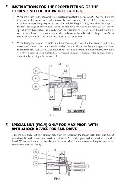
7)INSTRUCTIONS FOR THE PROPER FITTING OF THELOCKING NUT OF THE PROPELLER FIG.81. When it’s locked on the motor shaft, the nut must contact the 3 surfaces S1, S2, S3. Therefore,if a new nut has to be machined you must be sure that length L1 and L2 coincide preciselywith the corresponding lengths of prop hub, and that length L3 is greater than the length ofthe threaded edge of motor shaft. To check that the work is done properly, you just have tospread a very thin coat of Prussian blue on the 3 surfaces S1, S2, S3. Insert then the nut in itsseat in the hub and let the nut rotate softly in relation to the hub, with a light pressure. Whenthis is done, the 3 surfaces of the hub must be painted in blue.2. When fitting the prop on the motor shaft, it’s necessary to check that the threaded part of themotor shaft doesn’t touch the threaded end of the nut. Also, when the nut is tight, the bladesrotation on their axis does not get hard. In case the blades rotation movement becomes hard,you have to remove from surface S1 a very small amount of material. This operation can bedone simply by using a flat smooth file.Fig.88)SPECIAL NUT (FIG.9) ONLY FOR MAX PROP WITHANTI-SHOCK DEVICE FOR SAIL DRIVEUnlike the standard nut, this kind of nut, when it’s locked on the motor shaft, must lean ONLYto surfaces S1 and S2 and is secured by 4 devices: 2 threaded pins, and a central screw with adowel. When you mount the propeller on the motor shaft the same nut checking is necessary aspreviously described for fig. 8.Fig.9