Ultrasonic Measurement prosonic - VDT Industrie
Ultrasonic Measurement prosonic - VDT Industrie
Ultrasonic Measurement prosonic - VDT Industrie

Create successful ePaper yourself
Turn your PDF publications into a flip-book with our unique Google optimized e-Paper software.
Time<br />
Signal<br />
Time Dependent Threshold<br />
The time dependent threshold (TDT)<br />
detects echoes above a set level by<br />
gauging a collection of echoes (and<br />
noise) returned from various distances.<br />
This collection of echoes often is referred<br />
to as an envelope curve. Typically, the<br />
TDT is set higher for echoes closer to the<br />
sensor and lower for echoes farther away<br />
so that much of the unwanted noise is<br />
not detected. Because the TDT is fixed<br />
at the beginning and end of the envelope<br />
curve, it is not always able to respond to<br />
changes within the envelope curve from<br />
filling operations, material buildup, and<br />
dust formation. For many applications, it<br />
is implemented successfully.<br />
Floating Average Curve<br />
The floating average curve (FAC), a<br />
dynamic adaptation of the TDT, can<br />
respond to level changes that the TDT<br />
cannot detect. Like the TDT, the FAC<br />
filters out noise and unwanted echoes.<br />
However, the FAC is generated from a<br />
running average of envelope curves,<br />
enabling Prosonic to detect true level<br />
echoes even when acoustic conditions<br />
vary greatly. This method enables<br />
Prosonic to respond to changes within<br />
the envelope curve that the TDT is<br />
unable to manage.<br />
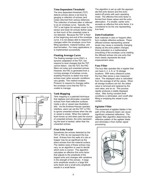
Tank Mapping<br />
Tank mapping is a patented technique<br />
that digitizes and eliminates unwanted<br />
echoes from fixed reflective surfaces<br />
inside a silo or vessel (see illustration<br />
left). Via the Endress+Hauser operator<br />
interface, users can set the TDT or FAC<br />
to ignore unwanted echoes when the silo<br />
or vessel is empty. When the material<br />
level moves up and down past the source<br />
of unwanted echoes, the echo representing<br />
the level is tracked, rather than the<br />
unwanted echoes.<br />
First Echo Factor<br />
Sometimes the echoes detected by the<br />
TDT or FAC do not represent the true<br />
level. Echoes from the walls of a silo or<br />
hopper may be as significant as the<br />
direct echoes from the material surface.<br />
The relative sizes of these echoes may<br />
vary, so an algorithm is used to decide<br />
which echo is correct. This algorithm<br />
calculates an effective first echo factor<br />
that adjusts to the amplitude of the<br />
largest echo and changes with variations<br />
in the strength of the echoes. A large<br />
echo amplitude results in a large first<br />
echo factor and a small echo amplitude<br />
results in a small factor.<br />
5<br />
The algorithm is set up with the appropriate<br />
first echo factors and first echo<br />
switch-off points with each operating<br />
mode. The effective first echo factor is<br />
formed from these values and the echo<br />
attenuation. If a smaller, earlier echo<br />
exceeds an effective first echo factor, it is<br />
considered to be the one representing<br />
true level.<br />
Zone Evaluation<br />
Bulk materials in silos or hoppers often<br />
form multiple reflective surfaces. These<br />
diffused echoes representing several<br />
levels may cause a constantly changing<br />
display as the echo pattern changes.<br />
Zone evaluation is a mathematical<br />
smoothing of the envelope curve melding<br />
the diffused echoes into one echo that<br />
more clearly represents the level<br />
measurement value.<br />
Fuzz Filter<br />
The fuzz filter operates like a register that<br />
can have 0, 2, 4, 8, or 16 storage<br />
locations. With every ultrasonic pulse,<br />
the fuzz filter stores a new measured<br />
value. The displayed value is calculated<br />
from the average of all the values. When<br />
all storage locations are full, the oldest<br />
value is removed and replaced by the<br />
next value, and so on. This process<br />
rapidly produces a stable displayed<br />
value. Jitter during constant level<br />
conditions is eliminated, and runoff after<br />
filling or emptying the vessel is prevented.<br />
Agitator Filter<br />
The movement of agitator blades in the<br />
path of the ultrasonic beam can cause<br />
significant undesired reflections. The<br />
agitator filter algorithm determines the<br />
reflective pattern of the agitator blade<br />
and eliminates it from further signal<br />
processing.