For bukh marine diesel engine type dv24 me - CLOUDS.NL
For bukh marine diesel engine type dv24 me - CLOUDS.NL
For bukh marine diesel engine type dv24 me - CLOUDS.NL
- No tags were found...

Create successful ePaper yourself
Turn your PDF publications into a flip-book with our unique Google optimized e-Paper software.
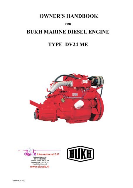
OWNER'S HANDBOOKFORBUKH MARINE DIESEL ENGINETYPE DV24 MEAABENRAA MOTORFABRIKHeinrich Callesen International A/S B.V.Næstmark 1e 30, Industrieweg P.O. 6A Box 793411 MG LOPIKDK 6200TelefoonAABENRAA0348 - 55 16 44Tel: +45Telefax74 62034820- 558808 73E-mail info@clouds.nlFax: +45 www.clouds.nl74 62 74 07E-mail: <strong>bukh</strong>@<strong>bukh</strong>.dkwww.<strong>bukh</strong>.dk009W0825-R02
OPERATING MANUAL FOR BUKH DV24ME ENGINESPreparation before first start1. Pour lubricating oil through filling hole on top of valve cover.Check that oil level is between the marks on the dipstick, placed atthe port side of the <strong>engine</strong>.Check oil level as <strong>me</strong>ntioned below:a) remove and wipe dipstickb) reinsert dipstick in the pipec) withdraw dipstick, check oil level.2. Pour lubricating oil through dipstick hole on the top of reverse- and reductiongear and check oil level as described in pos 1.3. Flexible sterntube: Lubricate the stuffing box with sterntube oil (outboard).Unscrew the filler plug and pour in oil until the bearing is full.Important:The stuffing box shall under no circumstances beforce-lubricated.These instructions are only valid for propeller equip<strong>me</strong>nt supplied by BUKH.If other equip<strong>me</strong>nt is mounted, we refer to the instructions given for this.4. We always recom<strong>me</strong>nd checking of oil level before start.5. Fill the fuel tank.6. Bleed the fuel system as below:a) Pump with the fuel lift pump handle until fuel is free from air bubblesseen in the hose to the fuel tank. After the pumping the pump handlemust be locked in top position.b) Loosen fuel pipe connection on the fuel valve, if neccessary.c) Turn the <strong>engine</strong> until fuel is free from air bubbles. Retighten the pipeconnection.Normally it will not be necessary to bleed the fuel system before starting but afterchanging the fuel filter ele<strong>me</strong>nt or carrying out any work on the fuel system itshould be bled in the following way: Loosen the bleed screw and operate thehand priming lever on the fuel lift pump until air-free fuel discharges from screw.Tighten bleed screw. Loosen high pressure pipe unions to injectors and turn<strong>engine</strong> until fuel discharges from pipes. Reconnect pipes to injectors. The <strong>engine</strong>will start in the normal way.AFTER THE ENGINE HAS BEEN TAKEN INTO USEBefore start1. The oil level of the <strong>engine</strong> should be checked every 14 days or every 25hours of running as described in ”Preparation before first start”. It is notnecessary to refill oil if the level is between the two marks on the dipstick.2. The oil level of the reduction gear should be checked every 14 days or every25 hours of running as described in ”Preparation before first start”.3. The sterntube stuffing box should be lubricated every 14 days or every 25hours of running.4. Check the quantity of fuel in the tank.Electric start with remote control and instru<strong>me</strong>nt panel1. Switch on the main switch.2. Put the <strong>marine</strong> gear in neutral position by <strong>me</strong>ans of the control handle.3. The <strong>engine</strong> is started by pushing in the key and turning it to the right.The starter should not work for more than 10-15 secs. continuously.Hand start1. Put the gear lever in neutral position.2. Turn decompression lever on valve cover clockwise as far as possible.3. Engage starting handle and crank <strong>engine</strong> as quickly as possible. Releasedecompressor by turning lever anticlockwise while cranking and <strong>engine</strong> will start.4. By hand start in cold weather you may achieve an easier start after having crankedthe <strong>engine</strong> with activated decompression lever before the starting procedure.Important: Never speed up a cold <strong>engine</strong>. Let it get warm first.009W0825-R02 - 5 -
OPERATING MANUAL FOR BUKH DV24ME ENGINESAfter Start1. When the <strong>engine</strong> has started, the RPM should be 800-1000 RPM when idling.2. Check the oil pressure. Normally this should be 2-4.5 bar. With cold <strong>engine</strong> the RPM should be kept down so that theoil pressure does not exceed 4.5 bar. When idling at warm <strong>engine</strong> the oil pressure must not be below 1 bar.3. Im<strong>me</strong>diately after start the oil pressure warning lamp goes out. During normal operation the lamp should stay off.4. Make sure that the charging control lamp goes out after the <strong>engine</strong> has started.5. Check the cooling water temperature frequently. The temperature should be in the area of 50 – 75 o C when <strong>engine</strong> iswarm.Manoeuvering1. With the control lever in central position the <strong>engine</strong> is idling, and the<strong>marine</strong> gear is in neutral (pos. 0). When the lever is moved forward inrange 1, the <strong>marine</strong> gear is engaged to "Ahead” first, and then inrange 2 the <strong>engine</strong> R.P.M. is increased. When the lever is movedfrom the central position to range 3, the <strong>marine</strong> gear is engaged to"Astern” first, and then in range 4 the <strong>engine</strong> R.P.M. is increased.2. Only engage "Ahead” or "Astern” when the <strong>engine</strong> is idling.3. To accelerate <strong>engine</strong> without engaging gear, operate gear releasebutton 5 and move control handle in either direction.4. Increase the load gradually from idling in the course of the first 15-20minutes shortly after the start of the <strong>engine</strong>.Stopping the <strong>engine</strong>1. Reduce the load gradually in the course of 15-20 minutes before stop.2. Reduce the <strong>engine</strong> to idling and put the gear in neutral position.3. Turn the ignition key left to stop position, pushing it slightly inwards.The key must not be left in this position after the <strong>engine</strong> has stoppeddue to the large current consumption of the stop solonoid. In this positionthe acoustic alarm will function, when the <strong>engine</strong> has stopped.4. Turn off the battery main switch.Running inTo secure long life and maximum power it is recom<strong>me</strong>nded to run the<strong>engine</strong> for the first 25 hours at not more than 80 pct. of the maximumoutput (about 3200 r.p.m.)You should avoid slow hauling as for instance towage. After the first 25 hoursit is recom<strong>me</strong>nded to change <strong>engine</strong> and gear oil and to tighten up the cylinderhead and to check or to possibly adjust the tension of the V-belt. Besides, it is recom<strong>me</strong>nded to let an authorized servicedealer go over <strong>engine</strong> and installation.MAINTENANCEBelt for alternatorTo be adjusted every 150 hours by turning the alternator round the centres ofsuspension. Tensioning should be so as to allow 8 - 10 mm deflection of the beltunder firm thumb pressure.Air inlet filterThis is a wire gauze filter to be rinsed in petrol and cleaned by a blast of compressedair after 300 hours' operating.Fuel filterA fuel filter is fitted between the fuel lift pump and the H.P. fuel pump. The filter is a disposableone which cannot be cleaned. It should be changed every 300 operating hours orif water contamination is suspected.Change the filter as follows:1. Drain off the fuel from the filter by slackening drain screw A in the bottom of the filtercasing B.2. Remove by hand or by <strong>me</strong>ans of a pair of tongs the filter casing and discard it.3. Clean the sealing surface of the filter holder C if necessary4. Fill the new filter casing with clean fuel through the holes at the top of sa<strong>me</strong>.5. Screw on the filter casing and tighten it by hand about half a turn after the gasket fitstightly.6. After changing the filter, bleed the fuel system as stated under ”Preparation for firststart”009W0825-R02 - 6 -
OPERATING MANUAL FOR BUKH DV24ME ENGINESFuel lift pumpThe fuel lift pump is a cam shaft driven sealed <strong>type</strong> diaphragm pump, which cannot bedismantled for repair or cleaning. It is recom<strong>me</strong>nded to install a water/dirt accumulating filter inthe suction line to the pump.After repairs the fuel system must be bled as described under ”Preparation for the first start” ifnecessary.Lubricating Oil SystemThe <strong>engine</strong> is pressure lubricated and the oil system has a built-in relief valve for controllingthe oil pressure. The oil level is checked as <strong>me</strong>ntioned before.Change of OilLubricating oil should be changed for the first ti<strong>me</strong> after 25 hours of running, later for every 150 hours or at least once ayear. It is recom<strong>me</strong>nded to change the oil when <strong>engine</strong> is warm, and the procedure is as follows:1. Remove the dipstick.2. Insert the sump pump suction hose into the hole and pump up the oil.3. When the sump is empty reinsert dipstick and pour fresh oil.4. If possible, drain the oil through the plug hole at the bottom of the sump.Recom<strong>me</strong>nded Lubricating OilModern <strong>diesel</strong> <strong>engine</strong>s demand heavy-duty oils with additives securing best operation conditions and longest life ti<strong>me</strong> of the<strong>engine</strong> under various conditions. Therefore use a first class HD-oil from a recognized oil company.Oil specifications as <strong>me</strong>ntioned in ”LUBRICATION OIL CHART”.When operating under difficult conditions, i.e. frequent cold starting, short operation periods, greatly varying loads, usequality ”Service D” and also use quality "Service CD" in case the sulphur content of fuel is higher than 1 %.Change of Lubricating Oil FilterLubricating oil filter cannot be cleaned, but should be changed every 150hours or once a year. To change the filter proceed as follows :1. Unscrew filter A and discard it.2. Clean the sealing surface of the <strong>engine</strong> B, and remove old gasket C if anyfrom old filter3. Mount new filter at once under clean conditions.4. Screw on filter until gasket fits tightly, tighten a further half turn.5. Fill with oil until normal level is reached.6. Start the <strong>engine</strong> and check that the filter is tight.Cooling SystemNormally the <strong>engine</strong> is supplied with salt water cooling-system, and with athermostat securing a constant <strong>engine</strong> temperature at varying load. Aboutcooling water temperature: See “Technical Dates”.In order to avoid corrosion of the cooling jackets a zinc-rod has been screwedin on the right side of the rear of the crankcase (see pos. 24 on page 3).The hexagon plug should be removed 2-3 ti<strong>me</strong>s a year for examination.If the zinc-rod is corroded more than 50% it should be replaced.Water circulation is effected by <strong>me</strong>ans of a rotary vane pump with neoprene impeller.Due to the varying temperatures and the one-sided deformation of the impeller during the long winter storage, the rubberimpeller should be replaced at the annual launching. Alternatively the impeller can be taken out and kept separately duringthis period. If water is coming out at the drain hole at the underside of the flange of the pump against the <strong>engine</strong>, it isnecessary to replace the gasket in the pump as soon as possible.Replace<strong>me</strong>nt of Impeller1. Remove the front cover of the pump after havingdrained off the water from the <strong>engine</strong>.2. The impeller can now be removed from the pumphousing by using tongs or two screwdriwers.3. Refit<strong>me</strong>nt of the impeller is made in reverse order.In case of defects on the thermostat, the thermostat will closefor the cooling water passage and the <strong>engine</strong> will thus be toohot. If the thermostat is removed, the shunt must be shut off.Too high cooling temperature will cause the blue lamp in thecontrol panel to light up and the acoustic alarm to function.Replace the thermostat insert by loosing the four nuts in the topcover of the thermostat housing, then remove the top cover.1. Thermostat housing2. Cooling water shunt3. Cooling water outlet009W0825-R02 - 7 -
OPERATING MANUAL FOR BUKH DV24ME ENGINESFreshwater CoolingWhen using freshwater cooling it will be possible to reach a higher operating temperature of 70-95°C which will prolong thelife of the <strong>engine</strong>. This cooling system is recom<strong>me</strong>nded for <strong>engine</strong>s operating for more than 500 hours a year. A pumpcirculates the freshwater in a closed system.This circulation pump is fitted on the front end of the <strong>engine</strong> and is driven by a V-belt.The freshwater circulates through the cooling jackets of the <strong>engine</strong> and through the heat exchanger fitted on the watercooled exhaust manifold.The freshwater is cooled in the heat exchanger by seawater which is pumped through by a big impeller pump like the oneused for direct seawater cooling.Too high cooling temperature will cause the blue lamp in the control panel to light up and the acoustic alarm to function.See “Winter storage of the <strong>engine</strong>” page 11.Frost precautionsTo avoid damaging the <strong>engine</strong>, drain the cooling water during frosty periods.To protect the <strong>engine</strong> against damage caused by frost, proceed as follows:1. Turn off the cock on the cooling water inlet skin fitting.2. Drain the cooling water off the <strong>engine</strong> by removing the plug above the lubricating oil filter on starboard side and underthe exhaust manifold, respectively.3. Clean up the drain holes with a nail, a steel wire or the like, so that any remaining water may drain out.4. Start the <strong>engine</strong> and let it run for 30 seconds to remove all the water from <strong>engine</strong> and exhaust manifold. Running forthat short ti<strong>me</strong> will cause no damage to the impeller of the pump.On <strong>engine</strong>s fitted with heat exchanger cooling it is recom<strong>me</strong>nded to use a mixture of min. 30% antifreeze liquid and 70%water and max. 50% antifreeze and 50% water as protection against corrosion and to secure the cooling water freezingtemperature to min. minus 15° Celsius or lower if required from climate conditions.However please also note when doing service on the boat that the mix of water and antifreeze can get aggressive andstart corrosion. If corrosion is found in the cooling system it can be caused by one of two conditions:1. The anti corrosion additives in the anti freezing liquid are exhausted and have evaporated.2. Oxidation due to incoming air causing an acid which is lowering the PH value.Therefore and also to keep the anti freezing properties it is recom<strong>me</strong>nded to change the cooling water and antifreezeevery 3 years min. Please also note the details provided by your supplier of antifreeze liquid normally stated on the can.Heat exchanger cooling water capacity for DV24 is 4.8 litres.Drain the raw water from the heat exchanger cooled <strong>engine</strong>s by taking off the seawater pump cover.Electrical SystemThe <strong>engine</strong> is equipped with a 12 volt electrical system consisting of a starter motor and an alternator, the max. chargingcurrent of which is 50 Amp.Electrical wiring diagram for the <strong>engine</strong> with control and instru<strong>me</strong>nt panels is shown later in this instruction.The level of the electrolyte in the battery should be checked every 14 days or every 25 operating hours. The level should be5-6 mm above the plates, if this is not the case top up as required with destilled or demineralized water.The battery must never be isolated from the alternator, when the <strong>engine</strong> is running.Warning! It is not allowed to connect additional equip<strong>me</strong>nt to the wiring system on the <strong>engine</strong>. Possible additionalequip<strong>me</strong>nt has to be connected directly to the terminals of the battery.NOTE!The starter must not be operated for more than 10 sec. If further operation is necessary, a pause of at least half a minutebefore starting attempt is repeated.Marine GearThe <strong>engine</strong> is equipped with a reverse-reduction gear. The reduction is 3:1 for AHEADand 2.36:1 for REVERSE.The <strong>marine</strong> gear will need no other attendance than regular change of oil. This to becarried out after 25 hours of operation, and then every 150 hours or once a year. Seeoil quality "Technical data" .The oil change is carried out by <strong>me</strong>ans of the lubricating oil bilge pump.The oil should be warm when draining.Refill new oil to the quantity og 1.1 liters through the dipstick hole.Check oil level on the dipstick.009W0825-R02 - 8 -
OPERATING MANUAL FOR BUKH DV24ME ENGINESPropeller equip<strong>me</strong>nt (As supplied by BUKH – for other <strong>type</strong>sconsult individual manufacturer’s instructions)Flexible stern tube: Every three years replace the three seal rings in thestuffing box “A” and the rubber hose “B” connecting stuffing boxand inter<strong>me</strong>diatetube “C” . Fill the flexible stuffing box “A” with Out-board gear oilthrough the filler hole in this or via the automatic stern tube lubrication “D”supplied as extra equip<strong>me</strong>nt to the stern tube arrange<strong>me</strong>nt.Normally the consumption of Out-board gear oil is not considerable, andtherefore, a sudden increase indicates defectivesealing rings.The container “D” should be mounted about 0.25 m above the water line.Sail driveAs an alternative to the <strong>marine</strong> gear, the <strong>engine</strong> can beequipped with a sail drive. The sail drive has the sa<strong>me</strong>function as the reverse-reduction gear.The reduction is 2.25:1 for AHEAD and for REVERSE.The sail drive will need no other attention than regularchange of oil. Change of oil should be carried out afterthe first 25 hours of operation, then every 150 hours oronce a year.Carry out the oil change when the boat is on land byloosening the screw ”D” in the bottom of the drive,enabling the oil to run out.Refill the fresh oil to a quantity of 3.3 ltr. through thefilter hole “B” at the top of the drive corresponding to theupper mark on the dipstick “A”.Use the sa<strong>me</strong> quality of oil as indicated iunder“Technical Data” for the <strong>marine</strong> gear.A replaceable zinc anode “C” is fitted on the sail drive.Check this anode once a year, replace it in case ofconsiderable corrosion.Only use a propeller which is insulated from the shaftand the leg!.Check that there is good electrical connection betweenthe zinc anode and the bearing hub through the twomounting screws.The sail drive is equipped with a double diaphragm “F”preventing penetration of seawater. In the doublediaphragm a sensor “E” is fitted which releases anacoustic alarm if water penetrates between the twodiaphragms. It is important for the sake of safety thatthis alarm is always serviceable. It should be checkedtwice a year by short-circuiting the connections 1 and 2on the plastic box next to the multiple plugs.When short-circuiting here by <strong>me</strong>ans of a piece of wireor a screw-driver, the buzzer should give alarm.The aluminium housing of the sail drive has beenspecially treated on the outside. Damage to surfacetreat<strong>me</strong>nt should be treated as soon as possible withspecial BUKH paint. The sail drive should be coatedwith the sa<strong>me</strong> paint as the rest of bottom of the boat.This paint must not contain copper.009W0825-R02 - 9 -
OPERATING MANUAL FOR BUKH DV24ME ENGINESGalvanic corrosionTo avoid corrosion of the propeller due to galvanic action itis advisable to fit a sacrificial zinc anode on the outside ofthe hull. To obtain a high degree of protection, electricalcontact between sacrificial zinc (anode) and propeller(cathode) has to be established.This is obtained by fitting the sacrifial zinc and connectingelectrically, as shown on the sketch.<strong>For</strong> the DV24 a sacrificial zinc of BERA 2B <strong>type</strong> isrecom<strong>me</strong>nded.The sacrificial zinc must not be painted or be otherwiseinsulated, as this will prevent the zinc from corroding.The sacrificial zinc must be checked everyti<strong>me</strong> the boat isashore, or at least twice a year.If the corrosion turns out to be very heavy, bigger anodes,e.g. 2 pcs. BERA 2B or 1 pc. BERA 1, should be fitted. Ifthere is no corrosion, check the electrical connections. Agood way of fitting the sacrificial zinc is to fold down one ofits flaps and to clamp it to thestern bearing by <strong>me</strong>ans of arustproof clip as shown on the sketch.Starting Instructions for BUKH Diesel Engine <strong>type</strong> DV24MEElectric Start:a) Switch on the main switch.b) Put the gear in neutral positionc) Turn the start switch to the rightuntil the <strong>engine</strong> startsHand Start:a) Put gear into neutral position.b) Put handle into crank claw.c) Lift decompression lever (1).Only for Cold Start (below 0 o C).Start pilot: Pos 1 - 2 - 3Pull and push the pump (2) 2-3 ti<strong>me</strong>s.d) Turn the starting handle as quickly as possible(clockwise), release the decompression lever,but keep on turning until the <strong>engine</strong> starts.Stopping the <strong>engine</strong>:Turn the start switch to the left.After <strong>engine</strong> stand still:Turn the switch right to neutral position.Filling the pressure tank (3):a) Open the cover.b) Put the gas cylinder on top of the valve and fill upthe tank to max. marking.009W0825-R02 - 10 -
OPERATING MANUAL FOR BUKH DV24ME ENGINESWINTER STORAGE OF THE ENGINE1. Carry out the following whilst the boat is still in the water:1. Run the <strong>engine</strong> until normal workingtemperature is reached.2. Drain off <strong>engine</strong> and gear oil with the oil bilge pump.3. Fill the <strong>engine</strong> and gearbox with preservative lubricating oil of a recognized make up to the upper mark on the dipstick.4. Fill the fuel tank with fuel preservative oil in the rate of mixture prescribed by the oil manufacturer.5. Start the <strong>engine</strong> and let it run for about 10 minutes to be sure that the fuel mixed with preservative oil has been flushedthrough the fuel system of the <strong>engine</strong>.6. Fill the fuel tank completely with fuel. Pay no special attention to the preservative oil previously added to the fuel as thisis consu<strong>me</strong>d normally and properly when service is resu<strong>me</strong>d in spring.2. On land the following procedure has to be carried out:1. Remove the <strong>engine</strong> cooling water drain plugs, drain off the sea water from the <strong>engine</strong> and refit plugs.2. <strong>For</strong> direct sea water cooled <strong>engine</strong>s: Remove the suction hose from the cooling water pump at the bottom cock and putthe hose into a bucket with freshwater containing preservative oil in the rate of mixture prescribed by the oilmanufacturer3. The outlet hose for the cooling water which goes into the exhaust elbow may be removed and returned to the bucketvia a length of hose so that the freshwater is able to circulate.Start the <strong>engine</strong> and the freshwater containingpreservative oil will be flushed through the <strong>engine</strong>.4. Stop the <strong>engine</strong> after 5 - 10 minutes and drain off the water. Ensure that after removing the drain plug (1 plug is placedin the block, and 1 plug in the exhaust manifold) all the water is drained off. This is done by cleaning the drain holeswith a nail,a steel wire or the like, so that any remaining water may drain out. Remove the impeller from the coolingwater pump, which will allow water in pump and pipes to be drained off. Keep the impeller separately in a dry placeduring the winter.5. A: <strong>For</strong> freshwater-cooled <strong>engine</strong>s:6. Drain the freshwater from the <strong>engine</strong> by removing the plugs as indicated for seawater cooled <strong>engine</strong>s.It is notnecessary to flush this system with freshwater containing preservative oil. If the <strong>engine</strong> is to be used in period of frost, itmust be protected against frost burst with a mixture of anti-freeze solution in the freshwater system - irrespective of theprotection to the freshwater system against the risk of frost - by removing the cover of the impeller pump and turningthe <strong>engine</strong> manually or with the starter motor.7. Remove the battery and store it separately during the winther in a dry and frost-free place. Fill up and charge thebattery before storing.8. Remove the air filter and turn the <strong>engine</strong> manually until each inlet valve opens alternately, during which about 1/2 cupof preservative oil is injected into each piston head. Turn the <strong>engine</strong> backwards and forwards manually in order tospread the preservative oil.9. Insert a clean, oil moistened rag (not cotton waste) into the inlet manifold.10. Insert another clean, oil moisted rag into the exhaustelbow aperture.11. Treat electrical connections with grease free from acid. Fill the multiple plugs with grease from the wire side.The <strong>engine</strong> is now preserved for winther storage and can be futher protected by covering of polythen sheeting, underwhich a bucket of silicagel should be placed.3. Preparation of <strong>engine</strong> before launching.1. Remove the oil moisted rags from the inlet manifold and the aperture of the exhaust elbow.2. Fit the cooling water pump impeller.3. Fit cooling water drain plugs.4. Drain the preservative lubricating oil from both <strong>engine</strong> and gearbox and fill up with fresh oil to the upper mark of thedipstick.5. Change the lubricating oil filter.6. Make sure - before starting up - that the oil on the piston heads is drained off. This is checked by turning the <strong>engine</strong>manually without operating the decompression lever.7. Examine the stern tube stuffing box and fill up with stern tube oil.8. Fit the battery after re-charging.9. Lubricate all moveable parts with oil.10. Check the anode.11. Check that there is electrical contact at the sterntube at the internal connection to the gearbox.009W0825-R02 - 11 -
OPERATING MANUAL FOR BUKH DV24ME ENGINESTECHNICAL MAIN DATAWORKING PRINCIPLE.............................................................. .................................... 4-STROKENUMBER OF CYLINDERS ........................................................ .................................... 2CYLINDER BORE/STROKE ...................................................... .................................... 85 mm / 85 mmSWEPT VOLUME ...................................................................... .................................... 0.964 LitresCOMPRESSION RATIO ............................................................ .................................... 18,5:1COMPRESSION PRESSURE ...........at 3600 rpm..................... .................................... 47 BarOUTPUT, CONTINOUS RATING ......at 2000 rpm..................... .................................... 15.8 BHP - 11.7 kWACCORDING TO ISO 3046at 2400 rpm..................... .................................... 17.9 BHP - 13.2 kWat 3000 rpm..................... .................................... 22.4 BHP - 16.5 kWat 3600 rpm..................... .................................... 24.0 BHP - 17.7 kWMAX. TORQUE .......................................................................... .................................... 5.7 Kpm at 2000 rpmMAX. AIR CONSUMPTION........................................................ .................................... 1476 Litres/minENGINE ROTATING, LOOKING AT FLYWHEEL ..................... .................................... CLOCWISEIDLING SPEED.......................................................................... .................................... 900 – 1200 RPMMAX INCLINATION, FORE AND AFT........................................ .................................... 12 oHEEL, MAX. CONTINOUS......................................................... .................................... 25 oENGINE NET WEIGHT.............................................................. .................................... 210 kgLOCATION OF ENGINE SERIAL NUMBER .............................. .................................... PORT SIDEEXHAUST TEMP. MAX/NORMAL.............................................. .................................... 600 o C – 580 o CVALVE TIMING AND INJECTION POINTFLYWHEEL DIAMETER ............................................................ .................................... 391 mmI<strong>NL</strong>ET VALVE OPENS.......................BEFORE TDC................. .................................... 32 o (arc <strong>me</strong>asure: 109 mm)I<strong>NL</strong>ET VALVE CLOSES ....................AFTER BDC.................... .................................... 64 o (arc <strong>me</strong>asure: 218 mm)EXHAUST VALVE OPENS ................BEFORE BDC................. .................................... 64 o (arc <strong>me</strong>asure: 218 mm)EXHAUST VALVE CLOSES .............AFTER TDC.................... .................................... 32 o (arc <strong>me</strong>asure: 109 mm)INJECTION STARTS………………….BEFORE TDC…………………………………… .... 14.7 o (arc <strong>me</strong>asure: 50 mm)VALVE CLEARANCES (COLD ENGINE) I<strong>NL</strong>ET/EXHAUST ...... .................................... 0.25 / 0.30 mmFUEL SYSTEM ......................................................................... .................................... DIRECT INJECTIONINJECTOR OPENING PRESSURE ........................................... .................................... 184 BarFUEL LIFT PUMP ...................................................................... .................................... CAM SHAFT DRIVEN DIAPHRAGM PUMPSTATIC PRESSURE OF FUEL LIFT PUMP .............................. .................................... 350 mBarFUEL FILTER ............................................................................ .................................... THROW AWAY FILTER INSERTFUEL QUALITY GAS OIL .......................................................... .................................... BS 2869 CLASS ALUBRICATING SYSTEMTYPE OF LUBRICATING OIL PUMP......................................... .................................... ROTARY VANE PUMPLUBRICATING OIL PRESSURE: WARM ENGINE/MINIMUM ... .................................... 2-4.5 Bar / 1 BarLUBRICATING OIL QUALITY .................................................... .................................... SERVICE CC or CDLUBRICATING OIL VISCOSITY ........BELOW +5 o C.................. .................................... SAE 10 or SAE 10W-30BETWEEN +5 o c and +25 o C ................................. SAE 20 or SAE 15W-40ABOVE +25 o C ................ .................................... SAE 30 or SAE 15W-40LUBRICATING OIL CONTENT INCL. FILTER ........................... .................................... 3.5 LitresLUBRICATING OIL FILTER ...................................................... .................................... THROW AWAY FILTER INSERTZF MARINEGEARLUBRICATING OIL QUALITY .................................................... .................................... API CC or CD, MILL-L-46152LUBRICATING OIL VISCOSITY ................................................ .................................... SAE 30 or SAE 15W-40LUBRICATING OIL TEMPERATURE......................................... .................................... MAX. 120 o CLUBRICATING OIL CONTENT .................................................. .................................... 1.1 LitresSTERN TUBE (FLEXIBLE) LUBRICANT.................................... .................................... OUTBOARD GEAR OILCOOLING WATER SYSTEMCOOLING WATER TEMPERATURE......................................... .................................... 50 – 75 o CTYPE OF PUMP/MAX. CAPACITY ........................................... .................................... CENTRIFUGAL / 11 Litres/minPUMP BACK PRESSURE/SUCTION HEAD…………………….. .................................... MAX. 6 m / MAX. 3 mCOOLING WATER CONTENT, DIRECT COOLING .................. .................................... 3.25 LitresCOOLING WATER CONTENT, HEAT EXCHANGER................ .................................... 4.8 LitresELECTRICAL SYSTEMBATTERY VOLTAGE/CAPACITY.............................................. .................................... 12 Volt / 88AhSTARTER TYPE / OUTPUT ...................................................... .................................... GEAR DRIVEN, 1.2 kWALTERNATOR TYPE / OUTPUT ............................................... .................................... BELT DRIVEN, 700 WENGINE STOP ......................................................................... .................................... SOLENOIDRELAY ....................................................................................... .................................... ELECTRONIC, BUILT-ONTORQUESCYLINDER HEAD BOLTS/BEARING TOP SECTION................ .................................... 118 +/- 5 Nm (12 +/- 0.5 Kpm)CONNECTING ROD BOLTS...................................................... .................................... 69 +/- 3 Nm (7 +/- 0.3 Kpm)FLYWHEEL/COUNTERWEIGHTS ............................................ .................................... 81 +/- 3 Nm (8.3 +/- 0.3 Kpm)FLEX. COUPLING...................................................................... .................................... 61 +/- 3 Nm (6.3 +/- 0.3 Kpm)ASSEMBLY OF FUEL VALVE ................................................... .................................... 59 +/- 3 Nm (6.0 +/- 0.3 Kpm)BRACKET FOR ENGINE SUPPORTS....................................... .................................... 69 +/- 3 Nm (7 +/- 0.3 Kpm)BRACKET FOR GEAR SUPPORTS .......................................... .................................... 39 +/- 3 Nm (4 +/- 0.3 Kpm)ZF- GEARBOX........................................................................... .................................... 25 +/- 5 Nm (2.5 +/- 0.5 Kpm)009W0825-R02 - 12 -
OPERATING MANUAL FOR BUKH DV24ME ENGINESRECOMMENDED MAINTENANCE AND A CHECK LIST FOR BUKH ENGINESCHECKRECTIFY IF NEEDEDWEEKLYMONTHLYEARLY1. Tightness of connections through hull:Y1.1 stern tube hull connection change sealing X2. Check of lubricating oil:2.1 a <strong>engine</strong> change oil - X X2.1.b <strong>engine</strong> check oil level - X2.2.a gearbox change oil - X2.2.b gearbox check oil level - X2.3 lubricating oil filter change - X3. Check of cooling watersystem:3.1 system system to be full fill up X3.2 anti freeze liquid check for minus 25°C. refill anti freeze liquid X3.3 cooling water connections tightness for leaks renew if leaking X3.4 condition of rubber hoses cracks and leaks renew X3.5 V-belt for cooling water pump adjust or renew - X3.6 thermostat renew after 5 years - X4. Check of fuel system:4.1 supply line clean water/fuel separa-torand check line bendsrepair if damaged orrenew4.2 fuel tank drain for water - X4.3 fuel filter change - X4.4 return line check for bends &damages5. Check of remote control cables:5.1 cables check easy operation andstroke sufficientrepair if damaged orrenewadjust cables6. Check of propeller shaft arrange<strong>me</strong>nt:6.1 rear stern tube bearing check clearance for bearing renew insertXinsert6.2 sufficient water flow to rear stern tube bearing check that water holes in clean holesXbearing housing are notblocked6.3 align<strong>me</strong>nt of gear flange and prop.shaft flange align<strong>me</strong>nt to be within 0.05- realign the <strong>engine</strong>X0.01mm6.4 stuffing box seals tightness renew all three seals X6.5 condition of rubber tube for stuffing box cracks renew X6.6 Out-Board gearoil. oillevel refill X6.7 propeller check size and condition renew if damaged X7. Starting of the <strong>engine</strong>:7.1 start with electrical start <strong>engine</strong> start within 2minutesif malfunctions -the<strong>engine</strong> must be servicedby a <strong>me</strong>chanic7.2 start with handstart sa<strong>me</strong> sa<strong>me</strong> X8. Engine maintenance8.1 valve clearance clearance adjust X8.2 electric starter rust protection of starterdrivespray rust protectionsprayX9. Running with <strong>engine</strong> - check:9.1 Idling speed to be 900-1200 RPM 900-1200 RPM adjust RPM X9.2 Full speed unload / min. 3700 RPM min. 3700 RPM adjust RPM X9.3 Full speed loaded with propeller 3300-3600 RPM adjust RPM X9.4 Cooling water temp. to be max. 75 degr. Celcius max. 75°C change termostat X9.5 Audible and visual alarms check function change senders, lampsXor switch9.6 Lubricating oil pressure min. 1.5 kg/cm² at idling adjust oil relief valve X9.7 Gearbox change from FW to Neutral to ASTERN check cables adjust X10. Air supply:10.1 air inlet filter renew - X11. Bateries:11.1 level of liquid check, refill renew X X X X11.2 voltage conditon charge renew XXEVERY5YEARSXXX009W0825-R02 - 13 -
OPERATING MANUAL FOR BUKH DV24ME ENGINESIRREGULAR OPERATION - CAUSES AND REMEDIES1. Engine does not startSYMPTOM CAUSE REMEDYInsufficient or very little compression Inlet and/or exhaust valves leaking Grind or replace the valves, mill the seatsInlet and/or exhaust valves stickingGrease valve stems with 2/3 gas oil and 1/3lub. Oil. If necessary clean the valves.Insufficient rocker arm clearanceAdjust to 0.25 mm inlet and 0.3 m<strong>me</strong>xhaust when <strong>engine</strong> is cold (turn left)Piston rings stuck in grooves or are worn Replace piston ringsValve springs broken or are weakReplace springsInsufficient or no pressure from fuel pump Air in fuel system or nozzles sticking Bleed or renew nozzlesThermo start out of order No fuel (valve leaking) Fill up (renew thermo-start)Check and/or replace switch andElectric supply out of orderconnections. Chech fuseEngine does not reach normal revs Unloaded battery or defective Battery to be charged or renewedStarter motor turns <strong>engine</strong> too slowly Loose or corroded connections Tighten or clean connections2. The <strong>engine</strong> starts, but stops soon afterThe <strong>engine</strong> starts, but stops soon after Empty fuel tank Refill and bleedAir in fuel systemBleedNozzle stickingReplace nozzleFuel filter chokedReplace filter ele<strong>me</strong>nt. Clean the tank3. The <strong>engine</strong> does not reach maximum outputDifficult to start None or insufficient compression See ”<strong>engine</strong> does not start”The <strong>engine</strong> revs. Is reduced considerablywhen loadedFuel supply choked up.Air/water in fuel systemCheck fuel system thoroughlyGovernor incorrectly adjusted or so<strong>me</strong>thingin the system works sluggishlyAdjust the governor. Check governorsystem and correct the errorHot <strong>engine</strong>(s<strong>me</strong>ll of heat) Insufficient cooling water supply Stop <strong>engine</strong>. Check cooling water pumpDamaged cylinder liner or bearings Check bearings, piston and cylinder, ifnecessary replace them4. The <strong>engine</strong> knocksThe <strong>engine</strong> runs unevenly Air/water in fuel system Bleed see ”<strong>engine</strong> does not start”5. The <strong>engine</strong> smokesBlack smoke Air inlet filter choked Clean filterInsufficient compressionSee ”<strong>engine</strong> does not start”Blue smokeThe lube oil passes piston and oil rings anpenetrates into combustion chamber, orReplace oil rings and possibly the pistonrings. Clean vacuum valvevacuum valve defectiveGrey smoke Thermostart valve is leaking Replace6. Excessive consumption of lubricating oilBlue smoke Oil- and piston rings are worn Replace oil- and piston rings, if requiredPiston and cylinder liner highly worn ReplaceDefective vacuum valveReplaceLub. oil leaks out of crankshaft bearings Worn oil seal ring Replace7. The <strong>engine</strong> gets too warm or too coldCooling water temperature too high Unsufficient cooling water supply caused(s<strong>me</strong>ll of heat)by:defective water pump, choked strainer ora defective thermostatInvestigate pump rotor for broken wings orlost driver screw. Clean strainer. Clean orreplace thermostatCooling water temperature too low Defective thermostat Clean or replace thermostat8. Insufficient or no lubrication oil pressureOil warning lamp lights up. Oil pressure Insufficient lube oil in the <strong>engine</strong>gauge indicates abnormally low oil pressureLeakage in lube oil systemRelief valve sticking or spring too weakCheck and refillTighten and refillClean bore and valve, stretch or replace thespring009W0825-R02 - 14 -
OPERATING MANUAL FOR BUKH DV24ME ENGINESLUBRICATING OIL CHARTLubricating oilfor <strong>engine</strong>:temp rangeAuxiliariesOIL COMPANY OIL TYPE HD OIL GRADE & QUALITYBP OIL VISCO 5000 SAE 5W-40 API SJ/CF XBP OIL Vanellus C4 Global SAE 15W-40 API CF-4/CF/SG X X X XBP OIL Vanellus C3 Extra API CF4/CE/SF X X X XBP OIL Outboard Gear Oil Universal XBP OIL Energol GR-XP 150 DIN 51 517 del. 3 XBP OIL Energol GR-XP 220 DIN 51 517 del. 3 XCALTEX Havoline Fully Synthetic SAE 5W-40 API SJ/CE XCALTEX Delo 350 Multigrade SAE 15W-40 API CF4/CJ X X X XCALTEX Outboard Gear Oil EP SAE 90 XCASTROL OIL CASTROL Syntruck SAE 5W-40 API CF XCASTROL OIL CASTROL RX Super Plus SAE 15W-40 API CH-4 X X X XCASTROL OIL CASTROL Marine Gear Oil SAE 90 XCHEVRON DELO 400 Synthetic SAE 10W-30 API CD/SG + SF XCHEVRON RPM HEAVY DUTY SAE 15W-40 API CD - II X X X XCHEVRON GEAR COMPOUND EP 220 ISO VG 220 XELF Elf Synthése 5W/40 SAE 5W-40 CD or CC XELF Performance 3D 15W-40 SAE 15W-40 CD or CC X XELF Performance 3D 10W-30 SAE 10W-30 CD or CC X XELF Outboard Gear Oil SAE 85W-90 XEXXON / ESSO EXXMAR CM SAE 15W-40 X X X XEXXON / ESSO ESSOLUBE XT301 SAE 15W-40 API CG-4 X X X XEXXON / ESSO ESSOLUBE XT301 SAE 15W-40 API CG-4 FZG11 XEXXON / ESSO SPARTAN EP220 ISO VG 220 XEXXON / ESSO GEAROIL GX SAE 80W-90 XMOBIL OIL MOBIL 1 0W-40 SAE 0W-40 API SJ/CF/EC X X X XMOBIL OIL MOBIL Delvac 1 SHC SAE 5W-40 API CE/CD X X X XMOBIL OIL MOBILGARD 1 SHC API CD/CF/CF2 X X X X XMOBIL OIL MOBILGARD HSD 15W-40 API CG-4/CF-4/CF/SH X X X XMOBIL OIL MOBIL Stern Tube Lubricant Outboard Gear Oil SAE 80-90 XNIPPON OIL COMPANY HIDIESEL S-3 SAVE SAE 15W-40 CD X X X X XNIPPON OIL COMPANY HIDIESEL S-3 SAVE SAE 10W-30 CD X X XNIPPON OIL COMPANY GEAR LUBE EHD SAE 90 XSHELL OIL Helix Ultra SAE 5W-40 XSHELL OIL Rimula X SAE 10W-30 XSHELL OIL Rimula X SAE 15W-40 X X XSHELL OIL Nautilus Marine Gear Oil SAE 90 XSHELL OIL Spirax GX SAE 80W-90 XSTATOIL LazerWay 5W-40 SAE 5W-40 API SL/CF XSTATOIL PowerWay 15W-40 SAE 15W-40 API CF4/SJ X X X XSTATOIL LoadWay EP 220 ISO VG 220 XSTATOIL GearWay G5 SAE 80W-90 XTEXACO Havoline <strong>For</strong>mula 3 Synthetic SAE 5W-40 API SJ/CF XTEXACO URSA Super LA SAE 15W-40 API CG-4 X X X XTEXACO GEARTEX EP-C SAE 80W-90 API GL-5 XTEXACO MEROPA 220 ISO VG 220 XDIRECTIONS FOR LUBRICATIONDesignation Application Point Capacity Incl. FilterEngine:DV24 Change first ti<strong>me</strong> after 25 h and every 150 h or once a year 3.5 LitreBW-7 Marine Gear Change first ti<strong>me</strong> after 25 h and every 150 h or once a year 1.1 LitreOil FilterChange every 150 h or once a yearStern Tube (flexible) Change every 3 yearsBelow – 15 o CBelow 5 o C5 o C – 25 o CAbove 25 o CBW-7 Marine gearStern tube (flexible)009W0825-R02 - 15 -
OPERATING MANUAL FOR BUKH DV24ME ENGINES009W0825-R02 - 16 -
OPERATING MANUAL FOR BUKH DV24ME ENGINESInstallation: DV24009W0825-R02 - 17 -
OPERATING MANUAL FOR BUKH DV24ME ENGINESGeneral Terms of Sale and Delivery1. IntroductionThe terms of sale and delivery specified below shallapply to all quotations, orders and consign<strong>me</strong>ntsunless otherwise specified in any other writtenagree<strong>me</strong>nt.2. QuotationsQuotations shall be subject to confirmation and thegoods being unsold. Aabenraa Motorfabrik reservesthe right to change unconfir<strong>me</strong>d quotations withoutnotice. The prices stated are exclusive of valueaddedtax and other duties.3. OrdersAny order shall be confir<strong>me</strong>d in writing by AabenraaMotorfabrik in order that an agree<strong>me</strong>nt onconsign<strong>me</strong>nts can be considered as binding.The order will be delivered at a confir<strong>me</strong>d pricesubject to price increases resulting from changes intrade conditions, duties, rates of exchange, rawmaterial supplies and similar conditions.Cancellation will only be accepted as perarrange<strong>me</strong>nt and against pay<strong>me</strong>nt of expenses incurred.Illustrations, di<strong>me</strong>nsioned sketches, as well as thecontents of leaflets, catalogues, circular letters, etcare approximate and with no binding effect.When carrying out the order, Aabenraa Motorfabrikreserves the right to make any changes which aredee<strong>me</strong>d necessary from a technical point of view.4. Terms of DeliveryDelivery will be “ex works” (INCO terms).Aabenraa Motorfabrik shall not be responsible fordelays or obstacles due to force majeure, forexample labour conflicts, fires, currency restrictions,shortage of labour and <strong>me</strong>ans of transport, generalscarcity of goods, restrictions on power and flaws inconsign<strong>me</strong>nts from subsuppliers or delay in suchconsign<strong>me</strong>nts, or any other conditions beyond theinfluence and control of Aabenraa Motorfabrik aswell as delay caused by the custo<strong>me</strong>r not havingsupplied sufficient technical information punctually.If the custo<strong>me</strong>r fails to observe the terms stipulatedfor pay<strong>me</strong>nt of the purchase price, AabenraaMotorfabrik shall be under no obligation to makedelivery.Aabenraa Motorfabrik shall not pay any damagesfor delays in delivery.5. PackagingPackaging is included in the price of the productand will not be taken back.6. Pay<strong>me</strong>ntPay<strong>me</strong>nt for all consign<strong>me</strong>nts shall be made directlyto Aabenraa Motorfabrik, Aabenraa, Denmark.The custo<strong>me</strong>r shall not be entitled to withholdpay<strong>me</strong>nt because of any counterclaims.If pay<strong>me</strong>nt should be effected later than thestipulated settling date, interest shall be paid onoverdue pay<strong>me</strong>nts at the rate of 1.5 per cent permonth or fraction of a month. Aabenraa Motorfabrikreserves the right to change the rate of interest.Any consign<strong>me</strong>nt shall remain the property ofAabenraa Motorfabrik until pay<strong>me</strong>nt has been madein full, and the custo<strong>me</strong>r must keep theconsign<strong>me</strong>nt insured against fire and damage - incase of <strong>marine</strong> plant, against sea risk - at the totalnew value from the date of ship<strong>me</strong>nt from thefactory and until full pay<strong>me</strong>nt has been effected.7. Re<strong>me</strong>dying DefectsIf the consign<strong>me</strong>nt should prove defective,Aabenraa Motorfabrik undertakes during the first 24months after the consign<strong>me</strong>nt has been put intoservice, however, not beyond 30 months from theday the consign<strong>me</strong>nt is reported to be ready forship<strong>me</strong>nt, in the case of spare parts, however, 3months from ship<strong>me</strong>nt, to re<strong>me</strong>dy defects which aredue to faulty design, materials or workmanship.However, the obligation to re<strong>me</strong>dy defects isconditional on the operating conditions contained orprovided in the agree<strong>me</strong>nt being observed and theconsign<strong>me</strong>nt being used and operated correctly.Defects which are due to 1) improper storagebefore or during installation, 2) insufficient maintenance,3) incorrect installation by the custo<strong>me</strong>r, 4)changes of the consign<strong>me</strong>nt carried out without thewritten consent of Aabenraa Motorfabrik, 5)incorrect or inexpedient repairs made by thecusto<strong>me</strong>r or others, 6) normal wear or deterioration,rust, corrosion, deposits caused by water, foreignmatter in pipes or the use of unsuitable oils, shallnot be covered by Aabenraa Motorfabrik’s obligationto re<strong>me</strong>dy defects.Unless otherwise stipulated, all transport andmounting of defective, repaired and replaced equip<strong>me</strong>ntshall be at the custo<strong>me</strong>r’s account and risk.Parts of the consign<strong>me</strong>nt which are notmanufactured by Aabenraa Motorfabrik will only bereplaced to the extent that Aabenraa Motorfabrik iscompensated for them by the subsupplier.Aabenraa Motorfabrik’s liability for defects is limitedto the above-<strong>me</strong>ntioned obligation. Aabenraa Motorfabrikshall only pay damages if it is proved that theloss caused by the defect is due to gross negligenceor intentional circumstances on the part ofAabenraa Motorfabrik. Aabenraa Motorfabrik shallin no circumstances be held liable for operationloss, loss of profits or any indirect damage.8. ArbitrationAny disputes are to be settled according to Danishlaw by arbitration in Copenhagen according to therules of the International Chamber of Com<strong>me</strong>rceand in accordance with the Danish Act onArbitration of 1972.009W0825-R02 - 18 -