Applied Biosystems 7900HT Fast Real-Time PCR System and SDS ...
Applied Biosystems 7900HT Fast Real-Time PCR System and SDS ...
Applied Biosystems 7900HT Fast Real-Time PCR System and SDS ...
- No tags were found...

You also want an ePaper? Increase the reach of your titles
YUMPU automatically turns print PDFs into web optimized ePapers that Google loves.
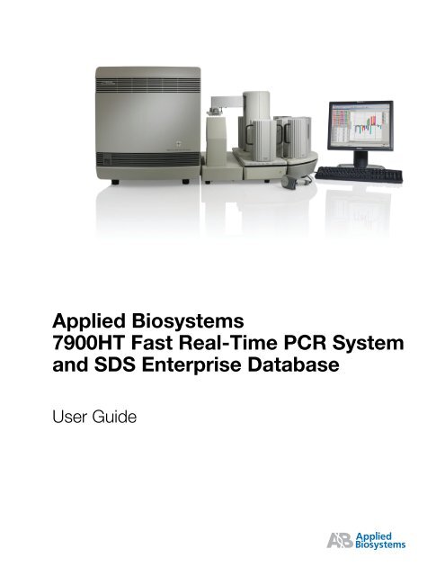
<strong>Applied</strong> <strong>Biosystems</strong><strong>7900HT</strong> <strong>Fast</strong> <strong>Real</strong>-<strong>Time</strong> <strong>PCR</strong> <strong>System</strong><strong>and</strong> <strong>SDS</strong> Enterprise DatabaseUser Guide
© Copyright 2004, <strong>Applied</strong> <strong>Biosystems</strong>. All rights reserved.For Research Use Only. Not for use in diagnostic procedures.Information in this document is subject to change without notice. <strong>Applied</strong> <strong>Biosystems</strong> assumes no responsibility for any errors that may appear in this document. Thisdocument is believed to be complete <strong>and</strong> accurate at the time of publication. In no event shall <strong>Applied</strong> <strong>Biosystems</strong> be liable for incidental, special, multiple, orconsequential damages in connection with or arising from the use of this document.AUTHORIZED THERMAL CYCLER: This <strong>Applied</strong> <strong>Biosystems</strong> <strong>7900HT</strong> <strong>Fast</strong> <strong>Real</strong>-<strong>Time</strong> <strong>PCR</strong> <strong>System</strong> Base Unit, Serial No___________, in combination with itsimmediately attached sample block modules, comprise an Authorized Thermal Cycler. The purchase price of this Base Unit includes the up-front fee component of alicense under United States Patent Nos. 4,683,195, 4,683,202 <strong>and</strong> 4,965,188, owned by Roche Molecular <strong>System</strong>s, Inc., <strong>and</strong> under corresponding claims in patentsoutside the United States, owned by F. Hoffmann-La Roche Ltd, covering the Polymerase Chain Reaction (“<strong>PCR</strong>”) process to practice the <strong>PCR</strong> process for internalresearch <strong>and</strong> development using this instrument. The running royalty component of that license may be purchased from <strong>Applied</strong> <strong>Biosystems</strong> or obtained by purchasingAuthorized Reagents. This instrument is also an Authorized Thermal Cycler for use with applications licenses available from <strong>Applied</strong> <strong>Biosystems</strong>. Its use withAuthorized Reagents also provides a limited <strong>PCR</strong> license in accordance with the label rights accompanying such reagents. Purchase of this product does not itselfconvey to the purchaser a complete license or right to perform the <strong>PCR</strong> process. Further information on purchasing licenses to practice the <strong>PCR</strong> process may beobtained by contacting the Director of Licensing at <strong>Applied</strong> <strong>Biosystems</strong>, 850 Lincoln Centre Drive, Foster City, California 94404.DISCLAIMER OF LICENSE: No rights for any application, including any in vitro diagnostic application, are conveyed expressly, by implication or by estoppelunder any patent or patent applications claiming homogeneous or real-time detection methods, including patents covering such methods used in conjunction with the<strong>PCR</strong> process or other amplification processes. The 5' nuclease detection assay <strong>and</strong> certain other homogeneous or real-time amplification <strong>and</strong> detection methods arecovered by United States Patent Nos. 5,210,015, 5,487,972, 5,804,375 <strong>and</strong> 5,994,056, owned by Roche Molecular <strong>System</strong>s, Inc.; by corresponding patents <strong>and</strong> patentapplications outside the United States, owned by F. Hoffmann-La Roche Ltd; <strong>and</strong> by United States Patent Nos. 5,538,848 <strong>and</strong> 6,030,787, <strong>and</strong> corresponding patents<strong>and</strong> patent applications outside the United States, owned by Applera Corporation. Purchase of this instrument conveys no license or right under the foregoing patents.Use of these <strong>and</strong> other patented processes in conjunction with the <strong>PCR</strong> process requires a license. For information on obtaining licenses, contact the Director ofLicensing at <strong>Applied</strong> <strong>Biosystems</strong>, 850 Lincoln Centre Drive, Foster City, California 94404, or The Licensing Department, Roche Molecular <strong>System</strong>s, Inc., 1145Atlantic Avenue, Alameda, California, 94501NOTICE TO PURCHASER: PLEASE REFER TO THE <strong>SDS</strong> ENTERPRISE DATABASE USER'S MANUAL FOR LIMITED LABEL LICENSE ORDISCLAIMER INFORMATION.JpegEncoder Licensing StatementThe JpegEncoder <strong>and</strong> its associated classes are Copyright © 1998, James R. Weeks <strong>and</strong> BioElectroMech. This software is based in part on the work of the IndependentJPEG Group.Redistribution <strong>and</strong> use in source <strong>and</strong> binary forms, with or without modification, are permitted provided that the following conditions are met:1. Redistributions of source code must retain the above copyright notice, this list of conditions, all files included with the source code, <strong>and</strong> the following disclaimer.2. Redistributions in binary form must reproduce the above copyright notice, this list of conditions <strong>and</strong> the following disclaimer in the documentation <strong>and</strong>/or othermaterials provided with the distribution.THIS SOFTWARE (JpegEncoder) IS PROVIDED BY THE AUTHOR AND CONTRIBUTORS ``AS IS'' AND ANY EXPRESS OR IMPLIED WARRANTIES,INCLUDING, BUT NOT LIMITED TO, THE IMPLIED WARRANTIES OF MERCHANTABILITY AND FITNESS FOR A PARTICULAR PURPOSE AREDISCLAIMED. IN NO EVENT SHALL THE AUTHOR OR CONTRIBUTORS BE LIABLE FOR ANY DIRECT, INDIRECT, INCIDENTAL, SPECIAL,EXEMPLARY, OR CONSEQUENTIAL DAMAGES (INCLUDING, BUT NOT LIMITED TO, PROCUREMENT OF SUBSTITUTE GOODS OR SERVICES;LOSS OF USE, DATA, OR PROFITS; OR BUSINESS INTERRUPTION) HOWEVER CAUSED AND ON ANY THEORY OF LIABILITY, WHETHER INCONTRACT, STRICT LIABILITY, OR TORT (INCLUDING NEGLIGENCE OR OTHERWISE) ARISING IN ANY WAY OUT OF THE USE OF THISSOFTWARE, EVEN IF ADVISED OF THE POSSIBILITY OF SUCH DAMAGE.TRADEMARKS:ABI PRISM, <strong>Applied</strong> <strong>Biosystems</strong>, MicroAmp, Primer Express, <strong>and</strong> VIC are registered trademarks <strong>and</strong> AB (Design), ABI PRISM, Applera, FAM, JOE, NED, ROX,TAMRA, <strong>and</strong> TET are trademarks of Applera Corporation or its subsidiaries in the US <strong>and</strong>/or certain other countries.AmpErase, AmpliTaq Gold, GeneAmp, <strong>and</strong> TaqMan are registered trademarks of Roche Molecular <strong>System</strong>s, Inc.SYBR is a registered trademark of Molecular Probes, Inc.Zymark is a registered trademark of Zymark Corporation.Windows <strong>and</strong> Windows NT are registered trademarks of Microsoft Corporation.All other trademarks are the sole property of their respective owners.Part Number 4351684 Rev. A09/2004DRAFTSeptember 1, 2004 11:38 am, 4351684A_Title.fm
ContentsPrefaceHow to Use This Guide . . . . . . . . . . . . . . . . . . . . . . . . . . . . . . . . . . . . . . . . . . . . . . . . . . . xiHow to Obtain More Information . . . . . . . . . . . . . . . . . . . . . . . . . . . . . . . . . . . . . . . . . . . xiiHow to Obtain Services <strong>and</strong> Support . . . . . . . . . . . . . . . . . . . . . . . . . . . . . . . . . . . . . . . xiiSafety <strong>and</strong> EMC Compliance InformationSafety Conventions Used in This Document . . . . . . . . . . . . . . . . . . . . . . . . . . . . . . . . . . xivSymbols on Instruments . . . . . . . . . . . . . . . . . . . . . . . . . . . . . . . . . . . . . . . . . . . . . . . . . xvSafety Labels on Instruments . . . . . . . . . . . . . . . . . . . . . . . . . . . . . . . . . . . . . . . . . . . . . xviGeneral Instrument Safety . . . . . . . . . . . . . . . . . . . . . . . . . . . . . . . . . . . . . . . . . . . . . . . xviiChemical Safety . . . . . . . . . . . . . . . . . . . . . . . . . . . . . . . . . . . . . . . . . . . . . . . . . . . . . . xviiiChemical Waste Safety . . . . . . . . . . . . . . . . . . . . . . . . . . . . . . . . . . . . . . . . . . . . . . . . . . xixElectrical Safety . . . . . . . . . . . . . . . . . . . . . . . . . . . . . . . . . . . . . . . . . . . . . . . . . . . . . . . . xxPhysical Hazard Safety . . . . . . . . . . . . . . . . . . . . . . . . . . . . . . . . . . . . . . . . . . . . . . . . . . xxiBiological Hazard Safety . . . . . . . . . . . . . . . . . . . . . . . . . . . . . . . . . . . . . . . . . . . . . . . . . xxiLaser Safety . . . . . . . . . . . . . . . . . . . . . . . . . . . . . . . . . . . . . . . . . . . . . . . . . . . . . . . . . . xxiBar Code Scanner Laser Safety . . . . . . . . . . . . . . . . . . . . . . . . . . . . . . . . . . . . . . . . . . xxiiWorkstation Safety . . . . . . . . . . . . . . . . . . . . . . . . . . . . . . . . . . . . . . . . . . . . . . . . . . . . xxiiiSafety <strong>and</strong> Electromagnetic Compatibility (EMC) St<strong>and</strong>ards . . . . . . . . . . . . . . . . . . . . xxiiiChapter 1Product Overview<strong>System</strong> Overview . . . . . . . . . . . . . . . . . . . . . . . . . . . . . . . . . . . . . . . . . . . . . . . . . . . . . . 1-2Section 1.1 Getting to Know the Hardware . . . . . . . . . . . . . . . . . . . . . . . . . . . . . . . . 1-3<strong>7900HT</strong> Instrument . . . . . . . . . . . . . . . . . . . . . . . . . . . . . . . . . . . . . . . . . . . . . . . . . . . . 1-4Computer . . . . . . . . . . . . . . . . . . . . . . . . . . . . . . . . . . . . . . . . . . . . . . . . . . . . . . . . . . . 1-6Bar Code Readers . . . . . . . . . . . . . . . . . . . . . . . . . . . . . . . . . . . . . . . . . . . . . . . . . . . . . 1-7Zymark Twister Microplate H<strong>and</strong>ler . . . . . . . . . . . . . . . . . . . . . . . . . . . . . . . . . . . . . . . . 1-8Compatible Consumables . . . . . . . . . . . . . . . . . . . . . . . . . . . . . . . . . . . . . . . . . . . . . . . 1-9Instrument Connections . . . . . . . . . . . . . . . . . . . . . . . . . . . . . . . . . . . . . . . . . . . . . . . 1-10Section 1.2 Getting to Know the Software . . . . . . . . . . . . . . . . . . . . . . . . . . . . . . . . 1-13Software Components . . . . . . . . . . . . . . . . . . . . . . . . . . . . . . . . . . . . . . . . . . . . . . . . 1-14<strong>SDS</strong> Software Related Files <strong>and</strong> Formats . . . . . . . . . . . . . . . . . . . . . . . . . . . . . . . . . . 1-15<strong>Applied</strong> <strong>Biosystems</strong> <strong>7900HT</strong> <strong>Fast</strong> <strong>Real</strong>-<strong>Time</strong> <strong>PCR</strong> <strong>System</strong> <strong>and</strong> <strong>SDS</strong> Enterprise Database User GuideDRAFTSeptember 1, 2004 11:40 am, 4351684ATOC.fmiii
Managing Sequence Detection <strong>System</strong> Data . . . . . . . . . . . . . . . . . . . . . . . . . . . . . . . 1-17Section 1.3 <strong>SDS</strong> Enterprise Database . . . . . . . . . . . . . . . . . . . . . . . . . . . . . . . . . . . 1-21About the <strong>SDS</strong> Enterprise Database Feature . . . . . . . . . . . . . . . . . . . . . . . . . . . . . . . 1-22About the <strong>SDS</strong> Enterprise Database Software Suite . . . . . . . . . . . . . . . . . . . . . . . . . . 1-25Database Modules for Large-Scale Analysis . . . . . . . . . . . . . . . . . . . . . . . . . . . . 1-25Database Management Utilities . . . . . . . . . . . . . . . . . . . . . . . . . . . . . . . . . . . . . . 1-26Database Design <strong>and</strong> Information Management . . . . . . . . . . . . . . . . . . . . . . . . . . . . . 1-27Supporting API Documentation . . . . . . . . . . . . . . . . . . . . . . . . . . . . . . . . . . . . . . . . . . 1-28Chapter 2Getting StartedGetting Started . . . . . . . . . . . . . . . . . . . . . . . . . . . . . . . . . . . . . . . . . . . . . . . . . . . . . . . 2-2Powering On the <strong>7900HT</strong> Instrument . . . . . . . . . . . . . . . . . . . . . . . . . . . . . . . . . . . . . . 2-4Using the <strong>SDS</strong> Software . . . . . . . . . . . . . . . . . . . . . . . . . . . . . . . . . . . . . . . . . . . . . . . . 2-7Basic Software Skills Tutorial . . . . . . . . . . . . . . . . . . . . . . . . . . . . . . . . . . . . . . . . . . . . 2-10Notes for Database Users . . . . . . . . . . . . . . . . . . . . . . . . . . . . . . . . . . . . . . . . . . . 2-11Lesson 1: Using Plate Documents . . . . . . . . . . . . . . . . . . . . . . . . . . . . . . . . . . . . 2-12Lesson 2: Viewing <strong>and</strong> Resizing Panes . . . . . . . . . . . . . . . . . . . . . . . . . . . . . . . . . 2-21Lesson 3: Using the Plate Grid . . . . . . . . . . . . . . . . . . . . . . . . . . . . . . . . . . . . . . . 2-23Lesson 4: Using the H<strong>and</strong>-Held Bar Code Reader . . . . . . . . . . . . . . . . . . . . . . . . 2-27Lesson 5: Using Contextual Menus . . . . . . . . . . . . . . . . . . . . . . . . . . . . . . . . . . . 2-28Lesson 6: Using Keyboard Shortcuts . . . . . . . . . . . . . . . . . . . . . . . . . . . . . . . . . . 2-28Using <strong>SDS</strong> Plate Documents . . . . . . . . . . . . . . . . . . . . . . . . . . . . . . . . . . . . . . . . . . . . 2-29Chapter 3Preparing a RunNotes for Database Users . . . . . . . . . . . . . . . . . . . . . . . . . . . . . . . . . . . . . . . . . . . . . . . 3-2Before You Begin . . . . . . . . . . . . . . . . . . . . . . . . . . . . . . . . . . . . . . . . . . . . . . . . . . . . . . 3-4Workflow Overview . . . . . . . . . . . . . . . . . . . . . . . . . . . . . . . . . . . . . . . . . . . . . . . . . . . . 3-5Quick Review: Powering On the <strong>7900HT</strong> Instrument . . . . . . . . . . . . . . . . . . . . . . . . . . 3-8Step 1 – Creating a Plate Document . . . . . . . . . . . . . . . . . . . . . . . . . . . . . . . . . . . . . . . 3-9Step 2 – Applying Detectors <strong>and</strong> Markers . . . . . . . . . . . . . . . . . . . . . . . . . . . . . . . . . . 3-11Step 3 – Configuring the Plate Document with Tasks . . . . . . . . . . . . . . . . . . . . . . . . . 3-16Step 4 – Setting the Passive Reference <strong>and</strong> Omitting Wells . . . . . . . . . . . . . . . . . . . . 3-18Step 5 – Programming the Plate Document Method . . . . . . . . . . . . . . . . . . . . . . . . . . 3-19Step 6 – Saving the Plate Document as a Template . . . . . . . . . . . . . . . . . . . . . . . . . . 3-24Step 7 – Creating a Plate Document from the Template . . . . . . . . . . . . . . . . . . . . . . . 3-26Step 8 – Applying Sample <strong>and</strong> Plate Information . . . . . . . . . . . . . . . . . . . . . . . . . . . . 3-28Step 9 – Running the Plate on the <strong>7900HT</strong> Instrument . . . . . . . . . . . . . . . . . . . . . . . . 3-29iv<strong>Applied</strong> <strong>Biosystems</strong> <strong>7900HT</strong> <strong>Fast</strong> <strong>Real</strong>-<strong>Time</strong> <strong>PCR</strong> <strong>System</strong> <strong>and</strong> <strong>SDS</strong> Enterprise Database User GuideDRAFTSeptember 1, 2004 11:40 am, 4351684ATOC.fm
Chapter 4Operating the InstrumentNotes for Database Users . . . . . . . . . . . . . . . . . . . . . . . . . . . . . . . . . . . . . . . . . . . . . . . 4-2Before You Begin . . . . . . . . . . . . . . . . . . . . . . . . . . . . . . . . . . . . . . . . . . . . . . . . . . . . . . 4-4Section 4.1 Consumable Preparation . . . . . . . . . . . . . . . . . . . . . . . . . . . . . . . . . . . . . 4-5Preventing Contamination . . . . . . . . . . . . . . . . . . . . . . . . . . . . . . . . . . . . . . . . . . . . . . . 4-6Compatible Consumables . . . . . . . . . . . . . . . . . . . . . . . . . . . . . . . . . . . . . . . . . . . . . . . 4-6Preparing Optical Plates for Use . . . . . . . . . . . . . . . . . . . . . . . . . . . . . . . . . . . . . . . . . . 4-8Preparing TaqMan Low Density Arrays for Use . . . . . . . . . . . . . . . . . . . . . . . . . . . . . 4-10About the Low Density Arrays . . . . . . . . . . . . . . . . . . . . . . . . . . . . . . . . . . . . . . . 4-10About the Centrifuge <strong>System</strong> . . . . . . . . . . . . . . . . . . . . . . . . . . . . . . . . . . . . . . . . 4-12About the Sealer . . . . . . . . . . . . . . . . . . . . . . . . . . . . . . . . . . . . . . . . . . . . . . . . . . 4-14Loading the TaqMan Low Density Arrays . . . . . . . . . . . . . . . . . . . . . . . . . . . . . . . 4-14Centrifuging the TaqMan Low Density Arrays . . . . . . . . . . . . . . . . . . . . . . . . . . . 4-16Sealing the TaqMan Low Density Arrays . . . . . . . . . . . . . . . . . . . . . . . . . . . . . . . 4-19Section 4.2 Running an Individual Plate . . . . . . . . . . . . . . . . . . . . . . . . . . . . . . . . . . 4-23Saving the Plate Document . . . . . . . . . . . . . . . . . . . . . . . . . . . . . . . . . . . . . . . . . . . . . 4-24Running a Single Plate (Using the <strong>SDS</strong> Software) . . . . . . . . . . . . . . . . . . . . . . . . . . . 4-25After the Run . . . . . . . . . . . . . . . . . . . . . . . . . . . . . . . . . . . . . . . . . . . . . . . . . . . . . . . . 4-29Section 4.3 Automated Operation . . . . . . . . . . . . . . . . . . . . . . . . . . . . . . . . . . . . . . 4-31Operating the Software with an <strong>SDS</strong> Enterprise Database . . . . . . . . . . . . . . . . . . . . . 4-32Operating the Software without an <strong>SDS</strong> Enterprise Database . . . . . . . . . . . . . . . . . . 4-34Adding a Plate Document to the Plate Queue (Using the <strong>SDS</strong> Software) . . . . . . 4-35Creating Plate Documents Using the Template Batch Utility . . . . . . . . . . . . . . . . 4-36Starting <strong>and</strong> Configuring the Automation Controller Software for Operation . . . . 4-39Running Plates Using the Automation Controller Software . . . . . . . . . . . . . . . . . . . . 4-41Loading Plates onto the Plate H<strong>and</strong>ler . . . . . . . . . . . . . . . . . . . . . . . . . . . . . . . . . 4-41Running the Instrument . . . . . . . . . . . . . . . . . . . . . . . . . . . . . . . . . . . . . . . . . . . . 4-43After the Run . . . . . . . . . . . . . . . . . . . . . . . . . . . . . . . . . . . . . . . . . . . . . . . . . . . . . . . . 4-44Chapter 5Analyzing End-Point DataEnd-Point Runs on the <strong>7900HT</strong> Instrument . . . . . . . . . . . . . . . . . . . . . . . . . . . . . . . . . 5-2Notes for Database Users . . . . . . . . . . . . . . . . . . . . . . . . . . . . . . . . . . . . . . . . . . . . . . . 5-3Section 5.1 Allelic Discrimination . . . . . . . . . . . . . . . . . . . . . . . . . . . . . . . . . . . . . . . . 5-5Overview . . . . . . . . . . . . . . . . . . . . . . . . . . . . . . . . . . . . . . . . . . . . . . . . . . . . . . . . . . . . 5-6Before You Begin . . . . . . . . . . . . . . . . . . . . . . . . . . . . . . . . . . . . . . . . . . . . . . . . . . . . . . 5-9Analysis Checklist . . . . . . . . . . . . . . . . . . . . . . . . . . . . . . . . . . . . . . . . . . . . . . . . . . . . 5-10Opening the Run Data . . . . . . . . . . . . . . . . . . . . . . . . . . . . . . . . . . . . . . . . . . . . . . . . . 5-11Analyzing an Allelic Discrimination Run . . . . . . . . . . . . . . . . . . . . . . . . . . . . . . . . . . . 5-12Calling <strong>and</strong> Scrutinizing Allelic Discrimination Data . . . . . . . . . . . . . . . . . . . . . . . . . . 5-13After the Analysis . . . . . . . . . . . . . . . . . . . . . . . . . . . . . . . . . . . . . . . . . . . . . . . . . . . . . 5-18<strong>Applied</strong> <strong>Biosystems</strong> <strong>7900HT</strong> <strong>Fast</strong> <strong>Real</strong>-<strong>Time</strong> <strong>PCR</strong> <strong>System</strong> <strong>and</strong> <strong>SDS</strong> Enterprise Database User GuideDRAFTSeptember 1, 2004 11:40 am, 4351684ATOC.fmv
Chapter 6Analyzing <strong>Real</strong>-<strong>Time</strong> DataNotes for Database Users . . . . . . . . . . . . . . . . . . . . . . . . . . . . . . . . . . . . . . . . . . . . . . . 6-2<strong>Real</strong>-<strong>Time</strong> Runs on the <strong>7900HT</strong> Instrument . . . . . . . . . . . . . . . . . . . . . . . . . . . . . . . . . 6-4Section 6.1 Absolute Quantification . . . . . . . . . . . . . . . . . . . . . . . . . . . . . . . . . . . . . . 6-5Overview . . . . . . . . . . . . . . . . . . . . . . . . . . . . . . . . . . . . . . . . . . . . . . . . . . . . . . . . . . . . 6-6Before You Begin . . . . . . . . . . . . . . . . . . . . . . . . . . . . . . . . . . . . . . . . . . . . . . . . . . . . . . 6-8Analysis Checklist . . . . . . . . . . . . . . . . . . . . . . . . . . . . . . . . . . . . . . . . . . . . . . . . . . . . . 6-9Opening the Run Data . . . . . . . . . . . . . . . . . . . . . . . . . . . . . . . . . . . . . . . . . . . . . . . . . 6-10Analyzing the Data . . . . . . . . . . . . . . . . . . . . . . . . . . . . . . . . . . . . . . . . . . . . . . . . . . . . 6-11Viewing Results . . . . . . . . . . . . . . . . . . . . . . . . . . . . . . . . . . . . . . . . . . . . . . . . . . . . . . 6-13After the Analysis . . . . . . . . . . . . . . . . . . . . . . . . . . . . . . . . . . . . . . . . . . . . . . . . . . . . . 6-14Section 6.2 Relative Quantification . . . . . . . . . . . . . . . . . . . . . . . . . . . . . . . . . . . . . . 6-15Overview . . . . . . . . . . . . . . . . . . . . . . . . . . . . . . . . . . . . . . . . . . . . . . . . . . . . . . . . . . . 6-16Algorithmic Manipulation of Raw Data . . . . . . . . . . . . . . . . . . . . . . . . . . . . . . . . . 6-17Automatic Outlier Removal . . . . . . . . . . . . . . . . . . . . . . . . . . . . . . . . . . . . . . . . . . 6-19Essential Experimental Components . . . . . . . . . . . . . . . . . . . . . . . . . . . . . . . . . . . . . . 6-20Getting Started . . . . . . . . . . . . . . . . . . . . . . . . . . . . . . . . . . . . . . . . . . . . . . . . . . . . . . 6-21Analysis Checklist . . . . . . . . . . . . . . . . . . . . . . . . . . . . . . . . . . . . . . . . . . . . . . . . . . . . 6-22Options for Analyzing Relative Quantification Data . . . . . . . . . . . . . . . . . . . . . . . . . . . 6-23Creating the Study . . . . . . . . . . . . . . . . . . . . . . . . . . . . . . . . . . . . . . . . . . . . . . . . . . . . 6-23Analyzing the Study . . . . . . . . . . . . . . . . . . . . . . . . . . . . . . . . . . . . . . . . . . . . . . . . . . . 6-26About the Analysis Settings . . . . . . . . . . . . . . . . . . . . . . . . . . . . . . . . . . . . . . . . . 6-26Specifying the Analysis Settings . . . . . . . . . . . . . . . . . . . . . . . . . . . . . . . . . . . . . . 6-29Analyzing the Study Data . . . . . . . . . . . . . . . . . . . . . . . . . . . . . . . . . . . . . . . . . . . 6-30Viewing Results . . . . . . . . . . . . . . . . . . . . . . . . . . . . . . . . . . . . . . . . . . . . . . . . . . . . . . 6-31After the Analysis . . . . . . . . . . . . . . . . . . . . . . . . . . . . . . . . . . . . . . . . . . . . . . . . . . . . . 6-35Section 6.3 Dissociation Curve Analysis . . . . . . . . . . . . . . . . . . . . . . . . . . . . . . . . . . 6-37Overview . . . . . . . . . . . . . . . . . . . . . . . . . . . . . . . . . . . . . . . . . . . . . . . . . . . . . . . . . . . 6-38Before You Begin . . . . . . . . . . . . . . . . . . . . . . . . . . . . . . . . . . . . . . . . . . . . . . . . . . . . . 6-39Analysis Checklist . . . . . . . . . . . . . . . . . . . . . . . . . . . . . . . . . . . . . . . . . . . . . . . . . . . . 6-40Opening the Run Data . . . . . . . . . . . . . . . . . . . . . . . . . . . . . . . . . . . . . . . . . . . . . . . . . 6-41Analyzing the Run Data . . . . . . . . . . . . . . . . . . . . . . . . . . . . . . . . . . . . . . . . . . . . . . . . 6-41Determining T m Values for the Analyzed Run . . . . . . . . . . . . . . . . . . . . . . . . . . . . . . . 6-42After the Analysis . . . . . . . . . . . . . . . . . . . . . . . . . . . . . . . . . . . . . . . . . . . . . . . . . . . . . 6-44Section 6.4 Procedure Reference . . . . . . . . . . . . . . . . . . . . . . . . . . . . . . . . . . . . . . . 6-45Setting the Baseline <strong>and</strong> Threshold Values . . . . . . . . . . . . . . . . . . . . . . . . . . . . . . . . . 6-46Eliminating Outlying Amplification . . . . . . . . . . . . . . . . . . . . . . . . . . . . . . . . . . . . . . . . 6-49After the Analysis . . . . . . . . . . . . . . . . . . . . . . . . . . . . . . . . . . . . . . . . . . . . . . . . . . . . . 6-52vi<strong>Applied</strong> <strong>Biosystems</strong> <strong>7900HT</strong> <strong>Fast</strong> <strong>Real</strong>-<strong>Time</strong> <strong>PCR</strong> <strong>System</strong> <strong>and</strong> <strong>SDS</strong> Enterprise Database User GuideDRAFTSeptember 1, 2004 11:40 am, 4351684ATOC.fm
Chapter 7Maintaining the InstrumentNotes for Database Users . . . . . . . . . . . . . . . . . . . . . . . . . . . . . . . . . . . . . . . . . . . . . . . 7-2Recommended Maintenance Schedule . . . . . . . . . . . . . . . . . . . . . . . . . . . . . . . . . . . . 7-4Section 7.1 Maintaining the <strong>7900HT</strong> Instrument . . . . . . . . . . . . . . . . . . . . . . . . . . . . 7-5Replacing the Sample Block . . . . . . . . . . . . . . . . . . . . . . . . . . . . . . . . . . . . . . . . . . . . . 7-6Changing the Plate Adapter . . . . . . . . . . . . . . . . . . . . . . . . . . . . . . . . . . . . . . . . . . . . 7-12Decontaminating the Sample Block . . . . . . . . . . . . . . . . . . . . . . . . . . . . . . . . . . . . . . 7-14Performing a Background Run . . . . . . . . . . . . . . . . . . . . . . . . . . . . . . . . . . . . . . . . . . 7-16Preparing the Background Plate or TaqMan Low Density Array . . . . . . . . . . . . . 7-17Creating a Plate Document for the Background Run . . . . . . . . . . . . . . . . . . . . . . 7-17Running the Prepared Background Plate or TaqMan Low Density Array . . . . . . 7-18Analyzing the Background Data . . . . . . . . . . . . . . . . . . . . . . . . . . . . . . . . . . . . . . 7-19Performing a Pure Dye Run . . . . . . . . . . . . . . . . . . . . . . . . . . . . . . . . . . . . . . . . . . . . . 7-20Preparing the Pure Dye Plates or Cards . . . . . . . . . . . . . . . . . . . . . . . . . . . . . . . . 7-22Preparing a Plate Document for a Pure Dye Plate or Card . . . . . . . . . . . . . . . . . 7-22Running the Prepared Pure Dye Plate or Card . . . . . . . . . . . . . . . . . . . . . . . . . . . 7-24Analyzing the Pure Dye Run . . . . . . . . . . . . . . . . . . . . . . . . . . . . . . . . . . . . . . . . . 7-25Adding Custom Dyes to the Pure Dye Set . . . . . . . . . . . . . . . . . . . . . . . . . . . . . . . . . 7-27Verifying Instrument Performance . . . . . . . . . . . . . . . . . . . . . . . . . . . . . . . . . . . . . . . . 7-30Section 7.2 Maintaining the Plate H<strong>and</strong>ler . . . . . . . . . . . . . . . . . . . . . . . . . . . . . . . . 7-35Automation Accessory Components <strong>and</strong> Stack Positions . . . . . . . . . . . . . . . . . . . . . 7-36Adjusting the Sensitivity of the Plate Sensor Switch . . . . . . . . . . . . . . . . . . . . . . . . . 7-37Aligning the Plate H<strong>and</strong>ler . . . . . . . . . . . . . . . . . . . . . . . . . . . . . . . . . . . . . . . . . . . . . . 7-41Aligning the Fixed-Position Bar Code Reader . . . . . . . . . . . . . . . . . . . . . . . . . . . . . . 7-49Cleaning <strong>and</strong> Replacing Gripper Finger Pads . . . . . . . . . . . . . . . . . . . . . . . . . . . . . . . 7-52Section 7.3 Maintaining the Computer <strong>and</strong> Software . . . . . . . . . . . . . . . . . . . . . . . 7-53General Computer Maintenance . . . . . . . . . . . . . . . . . . . . . . . . . . . . . . . . . . . . . . . . . 7-54Maintaining the <strong>SDS</strong> software . . . . . . . . . . . . . . . . . . . . . . . . . . . . . . . . . . . . . . . . . . . 7-55Chapter 8TroubleshootingTroubleshooting Table . . . . . . . . . . . . . . . . . . . . . . . . . . . . . . . . . . . . . . . . . . . . . . . . . . 8-2Low Precision or Irreproducibility . . . . . . . . . . . . . . . . . . . . . . . . . . . . . . . . . . . . . . . . . 8-5Background Runs . . . . . . . . . . . . . . . . . . . . . . . . . . . . . . . . . . . . . . . . . . . . . . . . . . . . . 8-9Pure Dye Runs . . . . . . . . . . . . . . . . . . . . . . . . . . . . . . . . . . . . . . . . . . . . . . . . . . . . . . . 8-11<strong>Real</strong>-<strong>Time</strong> Runs (Quantitative <strong>PCR</strong> <strong>and</strong> Dissociation Curves) . . . . . . . . . . . . . . . . . . 8-12End-Point Runs (Allelic Discrimination) . . . . . . . . . . . . . . . . . . . . . . . . . . . . . . . . . . . . 8-13Software <strong>and</strong> <strong>7900HT</strong> Instrument . . . . . . . . . . . . . . . . . . . . . . . . . . . . . . . . . . . . . . . . 8-14Zymark Twister Microplate H<strong>and</strong>ler <strong>and</strong> Fixed-Position Bar Code Reader . . . . . . . . 8-17TaqMan Low Density Array . . . . . . . . . . . . . . . . . . . . . . . . . . . . . . . . . . . . . . . . . . . . . 8-18<strong>SDS</strong> Enterprise Database . . . . . . . . . . . . . . . . . . . . . . . . . . . . . . . . . . . . . . . . . . . . . . 8-20<strong>Applied</strong> <strong>Biosystems</strong> <strong>7900HT</strong> <strong>Fast</strong> <strong>Real</strong>-<strong>Time</strong> <strong>PCR</strong> <strong>System</strong> <strong>and</strong> <strong>SDS</strong> Enterprise Database User GuideDRAFTSeptember 1, 2004 11:40 am, 4351684ATOC.fmvii
Appendix A Software ReferenceImporting Plate Document Setup Table Files . . . . . . . . . . . . . . . . . . . . . . . . . . . . . . . . A-2Setup Table Files . . . . . . . . . . . . . . . . . . . . . . . . . . . . . . . . . . . . . . . . . . . . . . . . . . . . . . A-41. File Version . . . . . . . . . . . . . . . . . . . . . . . . . . . . . . . . . . . . . . . . . . . . . . . . . . . . . A-5Plate Characteristics . . . . . . . . . . . . . . . . . . . . . . . . . . . . . . . . . . . . . . . . . . . . . . . . A-52. Plate Size . . . . . . . . . . . . . . . . . . . . . . . . . . . . . . . . . . . . . . . . . . . . . . . . . . . . . . . A-53. Plate ID . . . . . . . . . . . . . . . . . . . . . . . . . . . . . . . . . . . . . . . . . . . . . . . . . . . . . . . . A-5Detector Definitions . . . . . . . . . . . . . . . . . . . . . . . . . . . . . . . . . . . . . . . . . . . . . . . . . A-64. Number of Detectors . . . . . . . . . . . . . . . . . . . . . . . . . . . . . . . . . . . . . . . . . . . . . . A-65. Detectors List Header . . . . . . . . . . . . . . . . . . . . . . . . . . . . . . . . . . . . . . . . . . . . . A-66. Detectors List . . . . . . . . . . . . . . . . . . . . . . . . . . . . . . . . . . . . . . . . . . . . . . . . . . . A-7Marker Definitions . . . . . . . . . . . . . . . . . . . . . . . . . . . . . . . . . . . . . . . . . . . . . . . . . . A-87. Number of Markers (Allelic Discrimination Only) . . . . . . . . . . . . . . . . . . . . . . . . . A-88. Markers List Header (Allelic Discrimination Only) . . . . . . . . . . . . . . . . . . . . . . . . A-89. Markers List (Allelic Discrimination Only) . . . . . . . . . . . . . . . . . . . . . . . . . . . . . . A-9Well-Detector Information . . . . . . . . . . . . . . . . . . . . . . . . . . . . . . . . . . . . . . . . . . . A-1010. Well-Detector List Header . . . . . . . . . . . . . . . . . . . . . . . . . . . . . . . . . . . . . . . . A-1011. Well-Detector Definition List . . . . . . . . . . . . . . . . . . . . . . . . . . . . . . . . . . . . . . A-10Well-Marker Information . . . . . . . . . . . . . . . . . . . . . . . . . . . . . . . . . . . . . . . . . . . . A-1212. Well-Marker List Header (Allelic Discrimination Only) . . . . . . . . . . . . . . . . . . . A-1213. Well-Marker Definition List (Allelic Discrimination Only) . . . . . . . . . . . . . . . . . A-12Example Setup Table Files . . . . . . . . . . . . . . . . . . . . . . . . . . . . . . . . . . . . . . . . . . A-14Exporting Graphics . . . . . . . . . . . . . . . . . . . . . . . . . . . . . . . . . . . . . . . . . . . . . . . . . . . A-16Exporting Plate Document Data . . . . . . . . . . . . . . . . . . . . . . . . . . . . . . . . . . . . . . . . . A-16Operating the <strong>SDS</strong> Software from a Comm<strong>and</strong> Line . . . . . . . . . . . . . . . . . . . . . . . . . . A-18Using the Search Tool . . . . . . . . . . . . . . . . . . . . . . . . . . . . . . . . . . . . . . . . . . . . . . . . . A-20Connecting <strong>SDS</strong> Software to the Database . . . . . . . . . . . . . . . . . . . . . . . . . . . . . . . . A-22Appendix B Designing TaqMan Reagent-Based AssaysAssay Development Guidelines . . . . . . . . . . . . . . . . . . . . . . . . . . . . . . . . . . . . . . . . . . . B-2Design Tips for Allelic Discrimination Assays . . . . . . . . . . . . . . . . . . . . . . . . . . . . . . . . B-5Design Tips for Quantitative <strong>PCR</strong> Assays . . . . . . . . . . . . . . . . . . . . . . . . . . . . . . . . . . . B-6Appendix C Kits, Reagents, <strong>and</strong> ConsumablesInterchangeable Sample Block Modules <strong>and</strong> Accessories . . . . . . . . . . . . . . . . . . . . . . C-2Consumables <strong>and</strong> Disposables . . . . . . . . . . . . . . . . . . . . . . . . . . . . . . . . . . . . . . . . . . . C-3Instrument Maintenance <strong>and</strong> Verification . . . . . . . . . . . . . . . . . . . . . . . . . . . . . . . . . . . C-5TaqMan Pre-Developed Assays <strong>and</strong> Reagents . . . . . . . . . . . . . . . . . . . . . . . . . . . . . . . C-6Custom Oligonucleotide Synthesis . . . . . . . . . . . . . . . . . . . . . . . . . . . . . . . . . . . . . . . . C-6viii<strong>Applied</strong> <strong>Biosystems</strong> <strong>7900HT</strong> <strong>Fast</strong> <strong>Real</strong>-<strong>Time</strong> <strong>PCR</strong> <strong>System</strong> <strong>and</strong> <strong>SDS</strong> Enterprise Database User GuideDRAFTSeptember 1, 2004 11:40 am, 4351684ATOC.fm
Appendix D Theory of OperationFluorescent-Based Chemistries . . . . . . . . . . . . . . . . . . . . . . . . . . . . . . . . . . . . . . . . . . D-2<strong>Real</strong>-<strong>Time</strong> Data Analysis . . . . . . . . . . . . . . . . . . . . . . . . . . . . . . . . . . . . . . . . . . . . . . . . D-4Comparative C T Method of Relative Quantification . . . . . . . . . . . . . . . . . . . . . . . . . . . D-8Appendix E Limited Warranty StatementBibliographyGlossaryIndex<strong>Applied</strong> <strong>Biosystems</strong> <strong>7900HT</strong> <strong>Fast</strong> <strong>Real</strong>-<strong>Time</strong> <strong>PCR</strong> <strong>System</strong> <strong>and</strong> <strong>SDS</strong> Enterprise Database User GuideDRAFTSeptember 1, 2004 11:40 am, 4351684ATOC.fmix
x<strong>Applied</strong> <strong>Biosystems</strong> <strong>7900HT</strong> <strong>Fast</strong> <strong>Real</strong>-<strong>Time</strong> <strong>PCR</strong> <strong>System</strong> <strong>and</strong> <strong>SDS</strong> Enterprise Database User GuideDRAFTSeptember 1, 2004 11:40 am, 4351684ATOC.fm
PrefaceHow to Use This GuidePurpose of ThisGuideAudienceAssumptionsText ConventionsUser AttentionWordsSafety AlertWordsThe <strong>Applied</strong> <strong>Biosystems</strong> <strong>7900HT</strong> <strong>Fast</strong> <strong>Real</strong>-<strong>Time</strong> <strong>PCR</strong> <strong>System</strong> <strong>and</strong> <strong>SDS</strong> EnterpriseDatabase User Guide describes how to prepare, maintain, <strong>and</strong> troubleshoot the<strong>Applied</strong> <strong>Biosystems</strong> <strong>7900HT</strong> <strong>Fast</strong> <strong>Real</strong>-<strong>Time</strong> <strong>PCR</strong> <strong>System</strong> instrument, Zymark ®Twister Microplate H<strong>and</strong>ler, <strong>and</strong> <strong>SDS</strong> Enterprise Database.This guide is written for technicians, scientists, <strong>and</strong> researchers of all skill levels whowill use <strong>and</strong> maintain <strong>7900HT</strong> instruments with or without the <strong>SDS</strong> EnterpriseDatabase.This guide assumes that a <strong>Applied</strong> <strong>Biosystems</strong> technical representative has installedyour <strong>7900HT</strong> instrument, Plate H<strong>and</strong>ler, <strong>and</strong> <strong>SDS</strong> Enterprise Database <strong>and</strong> that youare familiar with:• Basic Microsoft ® Windows ® operations such as using the mouse, choosingcomm<strong>and</strong>s, working with windows, <strong>and</strong> using the hierarchical file system• Electronic storage devices (computer hard drives) <strong>and</strong> data files• Assay preparation <strong>and</strong> basic laboratory techniquesThis guide uses the following conventions:• Bold indicates user action. For example:Enter 0, then press Enter for each of the remaining fields.• Italics indicates new or important words <strong>and</strong> is used for emphasis. For example:Before performing a pure dye calibration, always perform a background run.• A right arrow bracket (>) separates successive comm<strong>and</strong>s you select from adrop-down or shortcut menu. For example:Select File > Open > Spot Set.Two user attention words appear in <strong>Applied</strong> <strong>Biosystems</strong> user documentation. Eachword implies a particular level of observation or action as described below:Note: Provides information that may be of interest or help but is not critical to theuse of the product.IMPORTANT! Provides information that is necessary for proper instrumentoperation, accurate chemistry kit use, or safe use of a chemical.Safety alert words also appear in user documentation. For more information,see “Safety Alert Words” on page xiv.<strong>Applied</strong> <strong>Biosystems</strong> <strong>7900HT</strong> <strong>Fast</strong> <strong>Real</strong>-<strong>Time</strong> <strong>PCR</strong> <strong>System</strong> <strong>and</strong> <strong>SDS</strong> Enterprise Database User GuideDRAFTSeptember 1, 2004 11:38 am, Preface.fmxi
PrefaceHow to Obtain More InformationRelatedDocumentationSend Us YourCommentsSee the following related documents for more information on the topics in this guide:• <strong>Applied</strong> <strong>Biosystems</strong> <strong>7900HT</strong> <strong>Fast</strong> <strong>Real</strong>-<strong>Time</strong> <strong>PCR</strong> <strong>System</strong> Quick Starts –Provide brief, procedures for performing application-specific tasks on the<strong>7900HT</strong> instrument.• Sequence Detections <strong>System</strong>s Software Online Help – Describes the SequenceDetection <strong>System</strong>s (<strong>SDS</strong>) Software <strong>and</strong> provides procedures for common tasks.• <strong>SDS</strong> Enterprise Database for the <strong>Applied</strong> <strong>Biosystems</strong> <strong>7900HT</strong> <strong>Fast</strong> <strong>Real</strong>-<strong>Time</strong><strong>PCR</strong> <strong>System</strong> Administrators Guide – Provides information for databaseadministrators who will be maintaining the <strong>SDS</strong> Enterprise Database, <strong>and</strong>provides information for systems integrators who will be working with the <strong>SDS</strong>Enterprise Database API.Note: For additional documentation, see “How to Obtain Services <strong>and</strong> Support” onpage xii.<strong>Applied</strong> <strong>Biosystems</strong> welcomes your comments <strong>and</strong> suggestions for improving itsuser documents. You can e-mail your comments to:techpubs@appliedbiosystems.comHow to Obtain Services <strong>and</strong> SupportTo contact <strong>Applied</strong> <strong>Biosystems</strong> Technical Support from North America bytelephone, call 1.800.899.5858.For the latest services <strong>and</strong> support information for all locations, go tohttp://www.appliedbiosystems.com, then click the link for Services <strong>and</strong> Support.At the Services <strong>and</strong> Support page, you can:• Search through frequently asked questions (FAQs)• Submit a question directly to Technical Support• Order <strong>Applied</strong> <strong>Biosystems</strong> user documents, M<strong>SDS</strong>s, certificates of analysis,<strong>and</strong> other related documents• Download PDF documents• Obtain information about customer training• Download software updates <strong>and</strong> patchesIn addition, the Services <strong>and</strong> Support page provides access to worldwide telephone<strong>and</strong> fax numbers to contact <strong>Applied</strong> <strong>Biosystems</strong> Technical Support <strong>and</strong> Salesfacilities.xii<strong>Applied</strong> <strong>Biosystems</strong> <strong>7900HT</strong> <strong>Fast</strong> <strong>Real</strong>-<strong>Time</strong> <strong>PCR</strong> <strong>System</strong> <strong>and</strong> <strong>SDS</strong> Enterprise Database User GuideDRAFTSeptember 1, 2004 11:38 am, Preface.fm
Safety <strong>and</strong> EMC Compliance InformationThis section includes the following topics:Safety Conventions Used in This Document. . . . . . . . . . . . . . . . . . . . . . . . . . . . . . xivSymbols on Instruments . . . . . . . . . . . . . . . . . . . . . . . . . . . . . . . . . . . . . . . . . . . . . .xvSafety Labels on Instruments . . . . . . . . . . . . . . . . . . . . . . . . . . . . . . . . . . . . . . . . . xviGeneral Instrument Safety. . . . . . . . . . . . . . . . . . . . . . . . . . . . . . . . . . . . . . . . . . . xviiChemical Safety . . . . . . . . . . . . . . . . . . . . . . . . . . . . . . . . . . . . . . . . . . . . . . . . . . xviiiChemical Waste Safety . . . . . . . . . . . . . . . . . . . . . . . . . . . . . . . . . . . . . . . . . . . . . . xixElectrical Safety . . . . . . . . . . . . . . . . . . . . . . . . . . . . . . . . . . . . . . . . . . . . . . . . . . . .xxPhysical Hazard Safety . . . . . . . . . . . . . . . . . . . . . . . . . . . . . . . . . . . . . . . . . . . . . . xxiBiological Hazard Safety. . . . . . . . . . . . . . . . . . . . . . . . . . . . . . . . . . . . . . . . . . . . . xxiLaser Safety. . . . . . . . . . . . . . . . . . . . . . . . . . . . . . . . . . . . . . . . . . . . . . . . . . . . . . . xxiBar Code Scanner Laser Safety. . . . . . . . . . . . . . . . . . . . . . . . . . . . . . . . . . . . . . . xxiiWorkstation Safety . . . . . . . . . . . . . . . . . . . . . . . . . . . . . . . . . . . . . . . . . . . . . . . . xxiiiSafety <strong>and</strong> Electromagnetic Compatibility (EMC) St<strong>and</strong>ards . . . . . . . . . . . . . . . xxiii<strong>Applied</strong> <strong>Biosystems</strong> <strong>7900HT</strong> <strong>Fast</strong> <strong>Real</strong>-<strong>Time</strong> <strong>PCR</strong> <strong>System</strong> <strong>and</strong> <strong>SDS</strong> Enterprise Database User GuideDRAFTSeptember 1, 2004 11:38 am, Safety.fmxiii
Safety <strong>and</strong> EMC Compliance InformationSafety Conventions Used in This DocumentSafety AlertWordsFour safety alert words appear in <strong>Applied</strong> <strong>Biosystems</strong> user documentation at pointsin the document where you need to be aware of relevant hazards. Each alertword–IMPORTANT, CAUTION, WARNING, DANGER–implies a particularlevel of observation or action, as defined below:DefinitionsIMPORTANT! – Indicates information that is necessary for proper instrumentoperation, accurate chemistry kit use, or safe use of a chemical.– Indicates a potentially hazardous situation that, if not avoided,may result in minor or moderate injury. It may also be used to alert against unsafepractices.– Indicates a potentially hazardous situation that, if not avoided,could result in death or serious injury.– Indicates an imminently hazardous situation that, if not avoided,will result in death or serious injury. This signal word is to be limited to the mostextreme situations.Except for IMPORTANTs, each safety alert word in an <strong>Applied</strong> <strong>Biosystems</strong>document appears with an open triangle figure that contains a hazard symbol. Thesehazard symbols are identical to the hazard icons that are affixed to <strong>Applied</strong><strong>Biosystems</strong> instruments (see “Safety Symbols” on page xv).ExamplesThe following examples show the use of safety alert words:IMPORTANT! You must create a separate a Sample Entry Spreadsheet for each96-well microtiter plate.The lamp is extremely hot. Do not touch the lamp until it hascooled to room temperature.CHEMICAL HAZARD. Formamide. Exposure causes eye,skin, <strong>and</strong> respiratory tract irritation. It is a possible developmental <strong>and</strong> birth defecthazard. Read the M<strong>SDS</strong>, <strong>and</strong> follow the h<strong>and</strong>ling instructions. Wear appropriateprotective eyewear, clothing, <strong>and</strong> gloves.ELECTRICAL HAZARD. Failure to ground the instrumentproperly can lead to an electrical shock. Ground the instrument according to theprovided instructions.xiv<strong>Applied</strong> <strong>Biosystems</strong> <strong>7900HT</strong> <strong>Fast</strong> <strong>Real</strong>-<strong>Time</strong> <strong>PCR</strong> <strong>System</strong> <strong>and</strong> <strong>SDS</strong> Enterprise Database User GuideDRAFTSeptember 1, 2004 11:38 am, Safety.fm
Symbols on InstrumentsSymbols on InstrumentsElectricalSymbols onInstrumentsThe following table describes the electrical symbols that may be displayed on<strong>Applied</strong> <strong>Biosystems</strong> instruments.Symbol Description Symbol DescriptionIndicates the On position of themain power switch.Indicates the Off position of themain power switch.Indicates a protectivegrounding terminal that mustbe connected to earth groundbefore any other electricalconnections are made to theinstrument.Indicates the On/Off position ofa push-push main powerswitch.Indicates a terminal that maybe connected to the signalground reference of anotherinstrument. This is not aprotected ground terminal.Indicates a terminal that canreceive or supply alternatingcurrent or voltage.Indicates a terminal that canreceive or supply alternating ordirect current or voltage.Safety SymbolsThe following table describes the safety symbols that may be displayed on<strong>Applied</strong> <strong>Biosystems</strong> instruments. Each symbol may appear by itself or in combinationwith text that explains the relevant hazard (see “Safety Labels on Instruments” onpage xvi). These safety symbols may also appear next to DANGERS, WARNINGS,<strong>and</strong> CAUTIONS that occur in the text of this <strong>and</strong> other product-support documents.Symbol Description Symbol DescriptionIndicates that you shouldconsult the manual for furtherinformation <strong>and</strong> to proceedwith appropriate caution.Indicates the presence of anelectrical shock hazard <strong>and</strong> toproceed with appropriatecaution.Indicates the presence of alaser inside the instrument <strong>and</strong>to proceed with appropriatecaution.Indicates the presence ofmoving parts <strong>and</strong> to proceedwith appropriate caution.Indicates the presence of a hotsurface or otherhigh-temperature hazard <strong>and</strong>to proceed with appropriatecaution.<strong>Applied</strong> <strong>Biosystems</strong> <strong>7900HT</strong> <strong>Fast</strong> <strong>Real</strong>-<strong>Time</strong> <strong>PCR</strong> <strong>System</strong> <strong>and</strong> <strong>SDS</strong> Enterprise Database User GuideDRAFTSeptember 1, 2004 11:38 am, Safety.fmxv
Safety <strong>and</strong> EMC Compliance InformationSafety Labels on InstrumentsThe following CAUTION, WARNING, <strong>and</strong> DANGER statements may be displayedon <strong>Applied</strong> <strong>Biosystems</strong> instruments in combination with the safety symbolsdescribed in the preceding section.EnglishCAUTION Hazardous chemicals. Read the Material SafetyData Sheets (M<strong>SDS</strong>s) before h<strong>and</strong>ling.CAUTION Hazardous waste. Read the waste profile (if any)in the site preparation guide for this instrument beforeh<strong>and</strong>ling or disposal.CAUTION Hazardous waste. Refer to M<strong>SDS</strong>(s) <strong>and</strong> localregulations for h<strong>and</strong>ling <strong>and</strong> disposal.WARNING Hot lamp.WARNING Hot. Replace lamp with an <strong>Applied</strong> <strong>Biosystems</strong>lamp.CAUTION Hot surface.DANGER High voltage.WARNING To reduce the chance of electrical shock, do notremove covers that require tool access. No user-serviceableparts are inside. Refer servicing to <strong>Applied</strong> <strong>Biosystems</strong>qualified service personnel.DANGER Class 3B laser radiation present when open <strong>and</strong>interlock defeated. Avoid direct exposure to laser beam.DANGER Class 3B laser radiation when open. Avoid directexposure to laser beam.DANGER Class 3B laser radiation present when open <strong>and</strong>interlock defeated. Do not stare directly into the beamDANGER Class 3B laser radiation present when open. Donot stare directly into the beam.DANGER Class 3B LED when open <strong>and</strong> interlock defeated.Do not stare directly into the beam.DANGER Class 3B LED when open. Do not stare directlyinto the beam.CAUTION Moving parts.FrancaisATTENTION Produits chimiques dangeureux. Lire les fichestechniques de sûreté de matériels avant la manipulation desproduits.ATTENTION Déchets dangereux. Lire les renseignementssur les déchets avant de les manipuler ou de les éliminer.ATTENTION Déchets dangereux. Lire les fiches techniquesde sûreté de matériels et la régulation locale associées à lamanipulation et l'élimination des déchets.AVERTISSEMENT Lampe brûlante.AVERTISSEMENT Composants brûlants. Remplacer lalampe par une lampe <strong>Applied</strong> <strong>Biosystems</strong>.ATTENTION Surface brûlante.DANGER Haute tension.AVERTISSEMENT Pour éviter les risques d'électrocution, nepas retirer les capots dont l'ouverture nécessite l'utilisationd'outils. L’instrument ne contient aucune pièce réparable parl’utilisateur. Toute intervention doit être effectuée par lepersonnel de service qualifié de <strong>Applied</strong> <strong>Biosystems</strong>.DANGER Class 3B rayonnement laser en cas d’ouverture etd’une neutralisation des dispositifs de sécurité. Eviter touteexposition directe avec le faisceau.DANGER Class 3B rayonnement laser en cas d’ouverture.Eviter toute exposition directe avec le faisceau.DANGER de Class 3B rayonnement laser en cas d'ouvertureet d'une neutralisation des dispositifs de securite. Evitertoute exposition directe avec le faisceau.DANGER de Class 3B rayonnement laser en casd'ouverture. Eviter toute exposition directe avec le faisceau.DANGER de Class 3B LED en cas d'ouverture et d'uneneutralisation des dispositifs de securite. Eviter touteexposition directe avec le faisceau.DANGER de Class 3B LED en cas d'ouverture. Eviter touteexposition directe avec le faisceau.ATTENTION Parties mobiles.xvi<strong>Applied</strong> <strong>Biosystems</strong> <strong>7900HT</strong> <strong>Fast</strong> <strong>Real</strong>-<strong>Time</strong> <strong>PCR</strong> <strong>System</strong> <strong>and</strong> <strong>SDS</strong> Enterprise Database User GuideDRAFTSeptember 1, 2004 11:38 am, Safety.fm
General Instrument SafetyGeneral Instrument SafetyPHYSICAL INJURY HAZARD. Use this product only asspecified in this document. Using this instrument in a manner not specified by<strong>Applied</strong> <strong>Biosystems</strong> may result in personal injury or damage to the instrument.Moving <strong>and</strong>Lifting theInstrumentMoving <strong>and</strong>Lifting St<strong>and</strong>-Alone Computers<strong>and</strong> MonitorsOperating theInstrumentPHYSICAL INJURY HAZARD. The instrument is to be moved<strong>and</strong> positioned only by the personnel or vendor specified in the applicable sitepreparation guide. If you decide to lift or move the instrument after it has beeninstalled, do not attempt to lift or move the instrument without the assistance ofothers, the use of appropriate moving equipment, <strong>and</strong> proper lifting techniques.Improper lifting can cause painful <strong>and</strong> permanent back injury. Depending on theweight, moving or lifting an instrument may require two or more persons.Do not attempt to lift or move the computer or the monitorwithout the assistance of others. Depending on the weight of the computer <strong>and</strong>/or themonitor, moving them may require two or more people.Things to consider before lifting the computer <strong>and</strong>/or the monitor:• Make sure that you have a secure, comfortable grip on the computer or themonitor when lifting.• Make sure that the path from where the object is to where it is being moved isclear of obstructions.• Do not lift an object <strong>and</strong> twist your torso at the same time.• Keep your spine in a good neutral position while lifting with your legs.• Participants should coordinate lift <strong>and</strong> move intentions with each other beforelifting <strong>and</strong> carrying.• Instead of lifting the object from the packing box, carefully tilt the box on itsside <strong>and</strong> hold it stationary while someone slides the contents out of the box.Ensure that anyone who operates the instrument has:• Received instructions in both general safety practices for laboratories <strong>and</strong>specific safety practices for the instrument.• Read <strong>and</strong> understood all applicable Material Safety Data Sheets (M<strong>SDS</strong>s). See“About M<strong>SDS</strong>s” on page xviii.PHYSICAL INJURY HAZARD. Use this instrument asspecified by <strong>Applied</strong> <strong>Biosystems</strong>. Using this instrument in a manner not specified by<strong>Applied</strong> <strong>Biosystems</strong> may result in personal injury or damage to the instrument.<strong>Applied</strong> <strong>Biosystems</strong> <strong>7900HT</strong> <strong>Fast</strong> <strong>Real</strong>-<strong>Time</strong> <strong>PCR</strong> <strong>System</strong> <strong>and</strong> <strong>SDS</strong> Enterprise Database User GuideDRAFTSeptember 1, 2004 11:38 am, Safety.fmxvii
Safety <strong>and</strong> EMC Compliance InformationChemical SafetyChemical HazardWarningCHEMICAL HAZARD. Before h<strong>and</strong>ling any chemicals, refer tothe Material Safety Data Sheet (M<strong>SDS</strong>) provided by the manufacturer, <strong>and</strong> observe allrelevant precautions.CHEMICAL HAZARD. All chemicals in the instrument, includingliquid in the lines, are potentially hazardous. Always determine what chemicals have beenused in the instrument before changing reagents or instrument components. Wearappropriate eyewear, protective clothing, <strong>and</strong> gloves when working on the instrument.CHEMICAL HAZARD. Four-liter reagent <strong>and</strong> waste bottles cancrack <strong>and</strong> leak. Each 4-liter bottle should be secured in a low-density polyethylene safetycontainer with the cover fastened <strong>and</strong> the h<strong>and</strong>les locked in the upright position. Wearappropriate eyewear, clothing, <strong>and</strong> gloves when h<strong>and</strong>ling reagent <strong>and</strong> waste bottles.CHEMICAL STORAGE HAZARD. Never collect or store wastein a glass container because of the risk of breaking or shattering. Reagent <strong>and</strong> wastebottles can crack <strong>and</strong> leak. Each waste bottle should be secured in a low-densitypolyethylene safety container with the cover fastened <strong>and</strong> the h<strong>and</strong>les locked in theupright position. Wear appropriate eyewear, clothing, <strong>and</strong> gloves when h<strong>and</strong>ling reagent<strong>and</strong> waste bottles.About M<strong>SDS</strong>sObtainingM<strong>SDS</strong>sChemical manufacturers supply current Material Safety Data Sheets (M<strong>SDS</strong>s) withshipments of hazardous chemicals to new customers. They also provide M<strong>SDS</strong>s withthe first shipment of a hazardous chemical to a customer after an M<strong>SDS</strong> has beenupdated. M<strong>SDS</strong>s provide the safety information you need to store, h<strong>and</strong>le, transport,<strong>and</strong> dispose of the chemicals safely.Each time you receive a new M<strong>SDS</strong> packaged with a hazardous chemical, be sure toreplace the appropriate M<strong>SDS</strong> in your files.You can obtain from <strong>Applied</strong> <strong>Biosystems</strong> the M<strong>SDS</strong> for any chemical supplied by<strong>Applied</strong> <strong>Biosystems</strong>. This service is free <strong>and</strong> available 24 hours a day.To obtain M<strong>SDS</strong>s:1. Go to https://docs.appliedbiosystems.com/msdssearch.html2. In the Search field, type in the chemical name, part number, or other informationthat appears in the M<strong>SDS</strong> of interest. Select a language, then click Search.3. Find the document of interest, right-click the document title, then select any ofthe following:• Open – To view the document• Print Target – To print the document• Save Target As – To download a PDF version of the document4. To have a copy of a document sent by fax or e-mail, select Fax or Email to theleft of the document title in the Search Results page, then click RETRIEVEDOCUMENTS at the end of the document list.5. After entering the required information, click View/Deliver SelectedDocuments Now.xviii<strong>Applied</strong> <strong>Biosystems</strong> <strong>7900HT</strong> <strong>Fast</strong> <strong>Real</strong>-<strong>Time</strong> <strong>PCR</strong> <strong>System</strong> <strong>and</strong> <strong>SDS</strong> Enterprise Database User GuideDRAFTSeptember 1, 2004 11:38 am, Safety.fm
Chemical Waste SafetyChemical SafetyGuidelines• Read <strong>and</strong> underst<strong>and</strong> the Material Safety Data Sheets (M<strong>SDS</strong>) provided by thechemical manufacturer before you store, h<strong>and</strong>le, or work with any chemicals orhazardous materials. (See “About M<strong>SDS</strong>s” on page xviii.)• Minimize contact with chemicals. Wear appropriate personal protectiveequipment when h<strong>and</strong>ling chemicals (for example, safety glasses, gloves, orprotective clothing). For additional safety guidelines, consult the M<strong>SDS</strong>.• Minimize the inhalation of chemicals. Do not leave chemical containers open.Use only with adequate ventilation (for example, fume hood). For additionalsafety guidelines, consult the M<strong>SDS</strong>.• Check regularly for chemical leaks or spills. If a leak or spill occurs, follow themanufacturer’s cleanup procedures as recommended on the M<strong>SDS</strong>.• Comply with all local, state/provincial, or national laws <strong>and</strong> regulations relatedto chemical storage, h<strong>and</strong>ling, <strong>and</strong> disposal.Chemical Waste SafetyChemical WasteHazardHAZARDOUS WASTE. Refer to Material Safety Data Sheets <strong>and</strong>local regulations for h<strong>and</strong>ling <strong>and</strong> disposal.CHEMICAL WASTE HAZARD. Wastes produced by <strong>Applied</strong><strong>Biosystems</strong> instruments are potentially hazardous <strong>and</strong> can cause injury, illness, or death.CHEMICAL STORAGE HAZARD. Never collect or store wastein a glass container because of the risk of breaking or shattering. Reagent <strong>and</strong> wastebottles can crack <strong>and</strong> leak. Each waste bottle should be secured in a low-densitypolyethylene safety container with the cover fastened <strong>and</strong> the h<strong>and</strong>les locked in theupright position. Wear appropriate eyewear, clothing, <strong>and</strong> gloves when h<strong>and</strong>ling reagent<strong>and</strong> waste bottles.Chemical WasteSafety Guidelines• Read <strong>and</strong> underst<strong>and</strong> the Material Safety Data Sheets (M<strong>SDS</strong>s) provided by themanufacturers of the chemicals in the waste container before you store, h<strong>and</strong>le,or dispose of chemical waste.• Provide primary <strong>and</strong> secondary waste containers. (A primary waste containerholds the immediate waste. A secondary container contains spills or leaks fromthe primary container. Both containers must be compatible with the wastematerial <strong>and</strong> meet federal, state, <strong>and</strong> local requirements for container storage.)• Minimize contact with chemicals. Wear appropriate personal protectiveequipment when h<strong>and</strong>ling chemicals (for example, safety glasses, gloves, orprotective clothing). For additional safety guidelines, consult the M<strong>SDS</strong>.• Minimize the inhalation of chemicals. Do not leave chemical containers open.Use only with adequate ventilation (for example, fume hood).For additionalsafety guidelines, consult the M<strong>SDS</strong>.• H<strong>and</strong>le chemical wastes in a fume hood.• After emptying the waste container, seal it with the cap provided.• Dispose of the contents of the waste tray <strong>and</strong> waste bottle in accordance withgood laboratory practices <strong>and</strong> local, state/provincial, or national environmental<strong>and</strong> health regulations.<strong>Applied</strong> <strong>Biosystems</strong> <strong>7900HT</strong> <strong>Fast</strong> <strong>Real</strong>-<strong>Time</strong> <strong>PCR</strong> <strong>System</strong> <strong>and</strong> <strong>SDS</strong> Enterprise Database User GuideDRAFTSeptember 1, 2004 11:38 am, Safety.fmxix
Safety <strong>and</strong> EMC Compliance InformationWaste ProfilesWaste DisposalA waste profile for the <strong>Applied</strong> <strong>Biosystems</strong> <strong>7900HT</strong> <strong>Fast</strong> <strong>Real</strong>-<strong>Time</strong> <strong>PCR</strong> <strong>System</strong> isprovided in the <strong>Applied</strong> <strong>Biosystems</strong> <strong>7900HT</strong> <strong>Fast</strong> <strong>Real</strong>-<strong>Time</strong> <strong>PCR</strong> <strong>System</strong> SitePreparation Guide.Waste profiles show the percentage compositions of the reagents in the waste streamgenerated during installation <strong>and</strong> during a typical user application, even though thetypical application may not be used in your laboratory.The waste profiles help you plan for the h<strong>and</strong>ling <strong>and</strong> disposal of waste generated byoperation of the instrument. Read the waste profiles <strong>and</strong> all applicable M<strong>SDS</strong>sbefore h<strong>and</strong>ling or disposing of chemical waste.If potentially hazardous waste is generated when you operate the instrument, youmust:• Characterize (by analysis if necessary) the waste generated by the particularapplications, reagents, <strong>and</strong> substrates used in your laboratory.• Ensure the health <strong>and</strong> safety of all personnel in your laboratory.• Ensure that the instrument waste is stored, transferred, transported, <strong>and</strong> disposedof according to all local, state/provincial, <strong>and</strong>/or national regulations.IMPORTANT! Radioactive or biohazardous materials may require special h<strong>and</strong>ling,<strong>and</strong> disposal limitations may apply.Electrical SafetyELECTRICAL SHOCK HAZARD. Severe electrical shock canresult from operating the <strong>Applied</strong> <strong>Biosystems</strong> <strong>7900HT</strong> <strong>Fast</strong> <strong>Real</strong>-<strong>Time</strong> <strong>PCR</strong> <strong>System</strong>without its instrument panels in place. Do not remove instrument panels. Highvoltagecontacts are exposed when instrument panels are removed from theinstrument.FusesELECTRICAL SHOCK HAZARD. Improper fuses or highvoltagesupply can damage the instrument wiring system <strong>and</strong> cause a fire. Beforepowering on the instrument, verify that the fuses are properly installed <strong>and</strong> that theinstrument voltage matches the power supply in your laboratory.FIRE HAZARD. For continued protection against the risk offire, replace fuses only with fuses of the type <strong>and</strong> rating specified for the instrument.PowerELECTRICAL HAZARD. Grounding circuit continuity is vitalfor the safe operation of equipment. Never operate equipment with the groundingconductor disconnected.ELECTRICAL HAZARD. Use properly configured <strong>and</strong>approved line cords for the voltage supply in your facility.ELECTRICAL HAZARD. Plug the system into a properlygrounded receptacle with adequate current capacity.xx<strong>Applied</strong> <strong>Biosystems</strong> <strong>7900HT</strong> <strong>Fast</strong> <strong>Real</strong>-<strong>Time</strong> <strong>PCR</strong> <strong>System</strong> <strong>and</strong> <strong>SDS</strong> Enterprise Database User GuideDRAFTSeptember 1, 2004 11:38 am, Safety.fm
Physical Hazard SafetyOvervoltageRatingThe <strong>Applied</strong> <strong>Biosystems</strong> <strong>7900HT</strong> <strong>Fast</strong> <strong>Real</strong>-<strong>Time</strong> <strong>PCR</strong> <strong>System</strong> has an installation(overvoltage) category of II, <strong>and</strong> is classified as portable equipmentPhysical Hazard SafetyMoving PartsPHYSICAL INJURY HAZARD. Moving parts can crush <strong>and</strong>cut. Keep h<strong>and</strong>s clear of moving parts while operating the instrument. Disconnectpower before servicing the instrument.PHYSICAL INJURY HAZARD. Do not operate the instrumentwithout the arm shield in place. Keep h<strong>and</strong>s out of the deck area when the instrumentis spotting.Biological Hazard SafetyGeneralBiohazardBIOHAZARD. Biological samples such as tissues, body fluids,<strong>and</strong> blood of humans <strong>and</strong> other animals have the potential to transmit infectiousdiseases. Follow all applicable local, state/provincial, <strong>and</strong>/or national regulations.Wear appropriate protective eyewear, clothing, <strong>and</strong> gloves. Read <strong>and</strong> follow theguidelines in these publications:• U.S. Department of Health <strong>and</strong> Human Services guidelines published inBiosafety in Microbiological <strong>and</strong> Biomedical Laboratories (stock no. 017-040-00547-4; http://bmbl.od.nih.gov)• Occupational Safety <strong>and</strong> Health St<strong>and</strong>ards, Bloodborne Pathogens(29 CFR§1910.1030; http://www.access.gpo.gov/nara/cfr/waisidx_01/29cfr1910a_01.html).Additional information about biohazard guidelines is available at:http://www.cdc.govLaser SafetyLaserClassificationThe <strong>Applied</strong> <strong>Biosystems</strong> <strong>7900HT</strong> <strong>Fast</strong> <strong>Real</strong>-<strong>Time</strong> <strong>PCR</strong> <strong>System</strong> uses a Class 3B laser.Under normal operating conditions, the instrument laser is categorized as a Class 3Blaser. When safety interlocks are disabled during certain servicing procedures, thelaser can cause permanent eye damage, <strong>and</strong>, therefore, is classified under thoseconditions as a Class 3B laser.The <strong>Applied</strong> <strong>Biosystems</strong> <strong>7900HT</strong> <strong>Fast</strong> <strong>Real</strong>-<strong>Time</strong> <strong>PCR</strong> <strong>System</strong> complies with 21CFR, 1040.10 <strong>and</strong> 1040.11, as applicable.The <strong>Applied</strong> <strong>Biosystems</strong> <strong>7900HT</strong> <strong>Fast</strong> <strong>Real</strong>-<strong>Time</strong> <strong>PCR</strong> <strong>System</strong> has been tested to <strong>and</strong>complies with the “Radiation Control for Health <strong>and</strong> Safety Act of 1968 PerformanceSt<strong>and</strong>ard CFR 1040.”<strong>Applied</strong> <strong>Biosystems</strong> <strong>7900HT</strong> <strong>Fast</strong> <strong>Real</strong>-<strong>Time</strong> <strong>PCR</strong> <strong>System</strong> <strong>and</strong> <strong>SDS</strong> Enterprise Database User GuideDRAFTSeptember 1, 2004 11:38 am, Safety.fmxxi
Safety <strong>and</strong> EMC Compliance InformationThe <strong>Applied</strong> <strong>Biosystems</strong> <strong>7900HT</strong> <strong>Fast</strong> <strong>Real</strong>-<strong>Time</strong> <strong>PCR</strong> <strong>System</strong> has been tested to <strong>and</strong>complies with st<strong>and</strong>ard EN60825-1, “Radiation Safety of Laser Products, EquipmentClassification, Requirements, <strong>and</strong> User’s Guide.”Laser SafetyRequirementsAdditional LaserSafetyInformationTo ensure safe laser operation:• The system must be installed <strong>and</strong> maintained by an <strong>Applied</strong> <strong>Biosystems</strong>Technical Representative.• All instrument panels must be in place on the instrument while the instrument isoperating. When all panels are installed, there is no detectable radiation present.If any panel is removed when the laser is operating (during service with safetyinterlocks disabled), you may be exposed to laser emissions in excess of theClass 3B rating.• Do not remove safety labels or disable safety interlocks.Refer to the user documentation provided with the laser for additional information ongovernment <strong>and</strong> industry safety regulations.LASER HAZARD. Lasers can burn the retina causingpermanent blind spots. Never look directly into the laser beam. Remove jewelry <strong>and</strong>other items that can reflect the beam into your eyes. Do not remove the instrumenttop or front panels. Wear proper eye protection <strong>and</strong> post a laser warning sign at theentrance to the laboratory if the top or front panels are removed for service.LASER BURN HAZARD. An overheated laser can causesevere burns if it comes in contact with the skin. DO NOT operate the laser when itcannot be cooled by its cooling fan. Always wear appropriate laser safety goggles.Bar Code Scanner Laser SafetyLaserClassificationLaser SafetyRequirementsThe bar code scanner included with the <strong>Applied</strong> <strong>Biosystems</strong> <strong>7900HT</strong> <strong>Fast</strong> <strong>Real</strong>-<strong>Time</strong><strong>PCR</strong> <strong>System</strong> is categorized as a Class 2 (II) laser.Class 2 (II) lasers are low-power, visible-light lasers that can damage the eyes.Never look directly into the laser beam. The scanner is designed to prevent humanaccess to harmful levels of laser light during normal operation, user maintenance, orduring prescribed service operations.LASER HAZARD. Class 2 (II) lasers can cause damage to eyes.Avoid looking into a Class 2 (II) laser beam or pointing a Class 2 (II) laser beam intoanother person’s eyes.xxii<strong>Applied</strong> <strong>Biosystems</strong> <strong>7900HT</strong> <strong>Fast</strong> <strong>Real</strong>-<strong>Time</strong> <strong>PCR</strong> <strong>System</strong> <strong>and</strong> <strong>SDS</strong> Enterprise Database User GuideDRAFTSeptember 1, 2004 11:38 am, Safety.fm
Workstation SafetyWorkstation SafetyCorrect ergonomic configuration of your workstation can reduce or prevent effectssuch as fatigue, pain, <strong>and</strong> strain. Minimize or eliminate these effects by configuringyour workstation to promote neutral or relaxed working positions.MUSCULOSKELETAL AND REPETITIVE MOTIONHAZARD. These hazards are caused by potential risk factors that include but are notlimited to repetitive motion, awkward posture, forceful exertion, holding staticunhealthy positions, contact pressure, <strong>and</strong> other workstation environmental factors.To minimize musculoskeletal <strong>and</strong> repetitive motion risks:• Use equipment that comfortably supports you in neutral working positions <strong>and</strong>allows adequate accessibility to the keyboard, monitor, <strong>and</strong> mouse.• Position the keyboard, mouse, <strong>and</strong> monitor to promote relaxed body <strong>and</strong> headpostures.Safety <strong>and</strong> Electromagnetic Compatibility (EMC) St<strong>and</strong>ardsThis section provides information on:• U.S. <strong>and</strong> Canadian Safety St<strong>and</strong>ards• Canadian EMC St<strong>and</strong>ard• European Safety <strong>and</strong> EMC St<strong>and</strong>ards• Australian EMC St<strong>and</strong>ardsU.S. <strong>and</strong>Canadian SafetySt<strong>and</strong>ardsCanadian EMCSt<strong>and</strong>ardEuropean Safety<strong>and</strong> EMCSt<strong>and</strong>ardsThis instrument has been tested to <strong>and</strong> complies with st<strong>and</strong>ard UL 3101-1, “SafetyRequirements for Electrical Equipment for Laboratory Use, Part 1: GeneralRequirements.”This instrument has been tested to <strong>and</strong> complies with st<strong>and</strong>ard CSA 1010.1, “SafetyRequirements for Electrical Equipment for Measurement, Control, <strong>and</strong> LaboratoryUse, Part 1: General Requirements.”This instrument has been tested to <strong>and</strong> complies with ICES-001, Issue 3: Industrial,Scientific, <strong>and</strong> Medical Radio Frequency Generators.SafetyThis instrument meets European requirements for safety (Low Voltage Directive73/23/EEC). This instrument has been tested to <strong>and</strong> complies with st<strong>and</strong>ardsEN 61010-1:2001, “Safety Requirements for Electrical Equipment for Measurement,Control <strong>and</strong> Laboratory Use, Part 1: General Requirements” <strong>and</strong> EN 61010-2-010,“Particular Requirements for Laboratory Equipment for the Heating of Materials.”EMCThis instrument meets European requirements for emission <strong>and</strong> immunity (EMCDirective 89/336/EEC). This instrument has been tested to <strong>and</strong> complies withst<strong>and</strong>ard EN 61326 (Group 1, Class B), “Electrical Equipment for Measurement,Control <strong>and</strong> Laboratory Use – EMC Requirements.”<strong>Applied</strong> <strong>Biosystems</strong> <strong>7900HT</strong> <strong>Fast</strong> <strong>Real</strong>-<strong>Time</strong> <strong>PCR</strong> <strong>System</strong> <strong>and</strong> <strong>SDS</strong> Enterprise Database User GuideDRAFTSeptember 1, 2004 11:38 am, Safety.fmxxiii
Safety <strong>and</strong> EMC Compliance InformationAustralian EMCSt<strong>and</strong>ardsThis instrument has been tested to <strong>and</strong> complies with st<strong>and</strong>ard AS/NZS 2064,“Limits <strong>and</strong> Methods Measurement of Electromagnetic Disturbance Characteristicsof Industrial, Scientific, <strong>and</strong> Medical (ISM) Radio-frequency Equipment.”xxiv<strong>Applied</strong> <strong>Biosystems</strong> <strong>7900HT</strong> <strong>Fast</strong> <strong>Real</strong>-<strong>Time</strong> <strong>PCR</strong> <strong>System</strong> <strong>and</strong> <strong>SDS</strong> Enterprise Database User GuideDRAFTSeptember 1, 2004 11:38 am, Safety.fm
Product Overview 11In This Chapter <strong>System</strong> Overview. . . . . . . . . . . . . . . . . . . . . . . . . . . . . . . . . . . . . . . . . . . . . . . . . . . 1-2Section 1.1 Getting to Know the Hardware. . . . . . . . . . . . . . . . . . . . . . . . . . . . . 1-3<strong>7900HT</strong> Instrument . . . . . . . . . . . . . . . . . . . . . . . . . . . . . . . . . . . . . . . . . . . . . . . . . 1-4Computer. . . . . . . . . . . . . . . . . . . . . . . . . . . . . . . . . . . . . . . . . . . . . . . . . . . . . . . . . 1-6Bar Code Readers . . . . . . . . . . . . . . . . . . . . . . . . . . . . . . . . . . . . . . . . . . . . . . . . . . 1-7Zymark Twister Microplate H<strong>and</strong>ler . . . . . . . . . . . . . . . . . . . . . . . . . . . . . . . . . . . . 1-8Compatible Consumables . . . . . . . . . . . . . . . . . . . . . . . . . . . . . . . . . . . . . . . . . . . . 1-9Instrument Connections. . . . . . . . . . . . . . . . . . . . . . . . . . . . . . . . . . . . . . . . . . . . . 1-10Section 1.2 Getting to Know the Software. . . . . . . . . . . . . . . . . . . . . . . . . . . . . 1-13Software Components . . . . . . . . . . . . . . . . . . . . . . . . . . . . . . . . . . . . . . . . . . . . . . 1-14<strong>SDS</strong> Software Related Files <strong>and</strong> Formats . . . . . . . . . . . . . . . . . . . . . . . . . . . . . . . 1-15Managing Sequence Detection <strong>System</strong> Data. . . . . . . . . . . . . . . . . . . . . . . . . . . . . 1-17Section 1.3 <strong>SDS</strong> Enterprise Database . . . . . . . . . . . . . . . . . . . . . . . . . . . . . . . . 1-21About the <strong>SDS</strong> Enterprise Database Feature. . . . . . . . . . . . . . . . . . . . . . . . . . . . . 1-22About the <strong>SDS</strong> Enterprise Database Software Suite. . . . . . . . . . . . . . . . . . . . . . . 1-25Database Design <strong>and</strong> Information Management . . . . . . . . . . . . . . . . . . . . . . . . . . 1-27Supporting API Documentation . . . . . . . . . . . . . . . . . . . . . . . . . . . . . . . . . . . . . . 1-28<strong>Applied</strong> <strong>Biosystems</strong> <strong>7900HT</strong> <strong>Fast</strong> <strong>Real</strong>-<strong>Time</strong> <strong>PCR</strong> <strong>System</strong> <strong>and</strong> <strong>SDS</strong> Enterprise Database User Guide 1-1DRAFTSeptember 1, 2004 11:38 am, CH_Overview.fm
EnterV C X Z < M N B > ? / F D S A K J H G L " 'R E W Q I U Y T O P [ ]- = Backspace9 0` _5 6 7 81 2 3 4+~Esc F1 F2 F3 F4 F5 F6 F7 F8 F9 F10 1 F F1203 2 1Enter4 6 58 7 9locklock lockl scro capsnumDownPageUpPageEndDeleteInsert Home*+Lock CapsTabShiftCtrl AltAlt CtrlShiftSysRqen ScrPrintBreakLockl Scro PauseNum LockChapter 1Product Overview<strong>System</strong> OverviewAbout the<strong>7900HT</strong>InstrumentThe <strong>Applied</strong> <strong>Biosystems</strong> <strong>7900HT</strong> <strong>Fast</strong> <strong>Real</strong>-<strong>Time</strong> <strong>PCR</strong> <strong>System</strong> is asecond-generation sequence detection system instrument designed for automated,high-throughput detection of fluorescent <strong>PCR</strong>-related chemistries. The instrument iscapable of real-time, end-point, <strong>and</strong> dissociation curve analysis of assays arrayed onmultiple formats. The <strong>7900HT</strong> instrument is optimized for use with<strong>Applied</strong> <strong>Biosystems</strong> chemistries for nucleic acid quantification <strong>and</strong> detection.Figure 1-1 The <strong>Applied</strong> <strong>Biosystems</strong> <strong>7900HT</strong> <strong>Fast</strong> <strong>Real</strong>-<strong>Time</strong> <strong>PCR</strong> <strong>System</strong> withthe Automation AccessorySupported Runs<strong>and</strong> ChemistriesThe <strong>Applied</strong> <strong>Biosystems</strong> <strong>7900HT</strong> <strong>Fast</strong> <strong>Real</strong>-<strong>Time</strong> <strong>PCR</strong> <strong>System</strong> provides two types ofruns to support the variety of <strong>PCR</strong>-related chemistries available from<strong>Applied</strong> <strong>Biosystems</strong> <strong>and</strong> affiliated companies.End-Point (Plate Read) ChemistryIn an end-point run, the thermal cycling of prepared plates containing reagents <strong>and</strong>template is performed on a dedicated thermal cycler. Following the <strong>PCR</strong>, the <strong>7900HT</strong>instrument is then used to collect a plate-read or a single reading of the fluorescenceresulting from the completed reactions. Allelic Discrimination is an example of anend-point chemistry that is directly supported by the <strong>SDS</strong> software.<strong>Real</strong>-<strong>Time</strong> ChemistryIn a real-time run, the thermal cycling of prepared plates containing reagents <strong>and</strong>template is performed on the <strong>7900HT</strong> instrument. During the run, the instrumentcollects data at each cycle of the <strong>PCR</strong>. The resulting data provides a chronologicalseries of measurements of the fluorescence resulting from the reactions. Examples ofreal-time chemistry include absolute quantification, relative quantification <strong>and</strong>dissociation curve analysis.1-2 <strong>Applied</strong> <strong>Biosystems</strong> <strong>7900HT</strong> <strong>Fast</strong> <strong>Real</strong>-<strong>Time</strong> <strong>PCR</strong> <strong>System</strong> <strong>and</strong> <strong>SDS</strong> Enterprise Database User GuideDRAFTSeptember 1, 2004 11:38 am, CH_Overview.fm
<strong>7900HT</strong> FAST <strong>Real</strong>-<strong>Time</strong> <strong>PCR</strong> <strong>System</strong>Section 1.1 Getting to Know the HardwareSection 1.1Getting to Know the HardwareIn This Section <strong>7900HT</strong> Instrument . . . . . . . . . . . . . . . . . . . . . . . . . . . . . . . . . . . . . . . . . . . . . . . . . 1-4Computer. . . . . . . . . . . . . . . . . . . . . . . . . . . . . . . . . . . . . . . . . . . . . . . . . . . . . . . . . 1-6Bar Code Readers . . . . . . . . . . . . . . . . . . . . . . . . . . . . . . . . . . . . . . . . . . . . . . . . . . 1-7Zymark Twister Microplate H<strong>and</strong>ler . . . . . . . . . . . . . . . . . . . . . . . . . . . . . . . . . . . . 1-8Compatible Consumables . . . . . . . . . . . . . . . . . . . . . . . . . . . . . . . . . . . . . . . . . . . . 1-9Instrument Connections. . . . . . . . . . . . . . . . . . . . . . . . . . . . . . . . . . . . . . . . . . . . . 1-10InstrumentComponentsThe <strong>Applied</strong> <strong>Biosystems</strong> <strong>7900HT</strong> <strong>Fast</strong> <strong>Real</strong>-<strong>Time</strong> <strong>PCR</strong> <strong>System</strong> consists of thecomponents shown in Figure 1-2.<strong>7900HT</strong> Instrument(see page 1-4)Microsoft ® Windows ®Compatible Computer(see page 1-6)GR2009<strong>7900HT</strong>Front view with RobotGR2009Fixed-PositionBar Code Reader(see page 1-7)Zymark ® TwisterMicroplate H<strong>and</strong>ler(see page 1-8)ExtendedCapacity Stacks(see page 1-7)H<strong>and</strong>-Held BarCode Reader(see page 1-7)Figure 1-2<strong>System</strong>Components of the <strong>Applied</strong> <strong>Biosystems</strong> <strong>7900HT</strong> <strong>Fast</strong> <strong>Real</strong>-<strong>Time</strong> <strong>PCR</strong><strong>Applied</strong> <strong>Biosystems</strong> <strong>7900HT</strong> <strong>Fast</strong> <strong>Real</strong>-<strong>Time</strong> <strong>PCR</strong> <strong>System</strong> <strong>and</strong> <strong>SDS</strong> Enterprise Database User Guide 1-3DRAFTSeptember 1, 2004 11:38 am, CH_Overview.fm
Chapter 1Product Overview<strong>7900HT</strong> InstrumentInternalComponentsThe <strong>7900HT</strong> instrument contains the hardware used for thermal cycling <strong>and</strong>detection of fluorescent chemistries (see page 1-2). Figure 1-3 illustrates the majorsubcomponents of the instrument described in detail below.Do not remove the cover to the <strong>Applied</strong> <strong>Biosystems</strong> <strong>7900HT</strong> <strong>Fast</strong><strong>Real</strong>-<strong>Time</strong> <strong>PCR</strong> <strong>System</strong>. Only a qualified <strong>Applied</strong> <strong>Biosystems</strong> service engineer mayrepair or adjust the internal components of the <strong>7900HT</strong> instrument. Failure to complycan result in serious injury <strong>and</strong>/or damage to the instrument.LaserCCDcameraReaderOpticssystemGR2112TrayDoorHeated clampAutomated plateh<strong>and</strong>ling systemSample block moduleFigure 1-3Internal Components of the <strong>7900HT</strong> InstrumentAutomated PlateH<strong>and</strong>ling <strong>System</strong>Heated ClampPHYSICAL HAZARD. Keep h<strong>and</strong>s <strong>and</strong> loose clothing awayfrom the instrument tray <strong>and</strong> door at all times during instrument operation. The<strong>7900HT</strong> instrument contains several internal components that can cause seriousphysical injury.The <strong>7900HT</strong> instrument features an automated plate-h<strong>and</strong>ling system to provide easyloading <strong>and</strong> removal of plates from the instrument. In combination with theautomation module, the plate-h<strong>and</strong>ling system allows unattended operation of theinstrument.PHYSICAL INJURY HAZARD. Hot Surface. Use care whenworking around this area to avoid being burned by hot components.The <strong>7900HT</strong> instrument has a heated clamp that provides optimal heat transfer <strong>and</strong>uniform heating during thermal cycling. When the instrument tray loads a plate, theclamp applies a downward pressure of 70 lbs (31.8 kg) onto the consumable. Duringthe run, the clamp maintains a constant temperature of 105 °C (±3 °C) to preventcondensation within the consumable wells.1-4 <strong>Applied</strong> <strong>Biosystems</strong> <strong>7900HT</strong> <strong>Fast</strong> <strong>Real</strong>-<strong>Time</strong> <strong>PCR</strong> <strong>System</strong> <strong>and</strong> <strong>SDS</strong> Enterprise Database User GuideDRAFTSeptember 1, 2004 11:38 am, CH_Overview.fm
<strong>7900HT</strong> InstrumentInterchangeableThermal CyclerBlocksThe <strong>7900HT</strong> instrument features a Peltier-based, interchangeable sample blockmodule based on the technology established in the GeneAmp ® <strong>PCR</strong> <strong>System</strong> 9700thermal cycler. The sample block module houses an internal Peltier heating/coolingunit (Figure 1-4). The sample block module is made of aluminum to provide anoptimal thermal transfer rate between the block <strong>and</strong> the optical plate or theTaqMan ® Low Density Array.PHYSICAL INJURY HAZARD. Hot Surface. Use care whenworking around this area to avoid being burned by hot components.Connection to the instrument(Do Not Touch)WarningGR2027Circuitry(Do Not Touch)GR2028GR2028Block insideinstrumentSample block(Do Not Touch)Top viewHeat sinks(Do Not Touch)Bottom viewFigure 1-4Components of the Interchangeable Thermal Cycler BlockThe interchangeable sample block module provides:• Wide temperature range: 4–99.9 °C• Accuracy: ±0.25 °C from 35–99.9 °C• Heat/cool rate: 1.5 °C per second• Temperature uniformity: ±0.5 °C (measured 30 sec after the clock starts)• Long-term stability <strong>and</strong> high reliability• Support for multiple consumable formats (see page 1-9)• Several different modes of operation including 9600 mode <strong>and</strong> programmabletemperature ramps (see page 3-21)• Reduced instrument downtime by allowing immediate replacement of the block(see page 7-6)• Easy access to the sample block for troubleshooting <strong>and</strong> maintenance(see page 7-6)Optics <strong>System</strong>IMPORTANT! Do not remove the cover to the <strong>7900HT</strong> instrument. Only a qualified<strong>Applied</strong> <strong>Biosystems</strong> service engineer may repair or adjust the internal components.<strong>Applied</strong> <strong>Biosystems</strong> <strong>7900HT</strong> <strong>Fast</strong> <strong>Real</strong>-<strong>Time</strong> <strong>PCR</strong> <strong>System</strong> <strong>and</strong> <strong>SDS</strong> Enterprise Database User Guide 1-5DRAFTSeptember 1, 2004 11:38 am, CH_Overview.fm
Chapter 1Product OverviewComputerFunctionsA Microsoft Windows-compatible computer is required to operate the <strong>Applied</strong><strong>Biosystems</strong> <strong>7900HT</strong> <strong>Fast</strong> <strong>Real</strong>-<strong>Time</strong> <strong>PCR</strong> <strong>System</strong> <strong>and</strong> the Zymark TwisterMicroplate H<strong>and</strong>ler. Through the <strong>SDS</strong> <strong>and</strong> Automation Controller Software, thecomputer:• Provides the interface for programming <strong>and</strong> operating the instrument• Coordinates the operation of the <strong>7900HT</strong> instrument, automation module, <strong>and</strong>the bar code readers• Provides storage <strong>and</strong> management of the data produced by the <strong>7900HT</strong>instrument• Provides the local area network (LAN) connection to the <strong>SDS</strong> EnterpriseDatabase (if available)<strong>System</strong>RequirementsThe system requirements for the computer used to operate the <strong>7900HT</strong> instrumentvary with the version of the <strong>SDS</strong> software. To determine the system requirements foryour instrument, check the release notes accompanying your version of the <strong>SDS</strong>software.The release notes for the <strong>SDS</strong> software are in the following location:D:\<strong>Applied</strong><strong>Biosystems</strong>\<strong>SDS</strong>2.2.1\ReleaseNotes.txtNote: You can use the Microsoft Notepad, Wordpad, or Word software to read therelease notes text file.Hard DrivePartitionsDuring installation of the <strong>7900HT</strong> instrument, the <strong>Applied</strong> <strong>Biosystems</strong> service engineerpartitions the computer hard drive to create the logical drives shown in the table below.Primary Hard DriveDriveSize(GB)ContainsC 2 Operating system files **<strong>Applied</strong> <strong>Biosystems</strong> recommends that you do not install programs to the C drive. Thecomputer will boot faster if the C drive contains only the operating system.†Software required for the operation of the bar code reader.D ≥25 • <strong>SDS</strong> Software• Automation Controller Software• Zymark Twister Software• LAVA Software †• Additional Third-Party Software• <strong>SDS</strong> <strong>7900HT</strong> Documents• (Optional) <strong>SDS</strong> EnterpriseDatabase Client SoftwareNote: The partitions shown above represent the basic drive architecture required bythe <strong>SDS</strong> software. The actual number <strong>and</strong> size of the partitions <strong>and</strong> drives availableon your computer vary depending on the model of computer accompanying yourinstrument.1-6 <strong>Applied</strong> <strong>Biosystems</strong> <strong>7900HT</strong> <strong>Fast</strong> <strong>Real</strong>-<strong>Time</strong> <strong>PCR</strong> <strong>System</strong> <strong>and</strong> <strong>SDS</strong> Enterprise Database User GuideDRAFTSeptember 1, 2004 11:38 am, CH_Overview.fm
<strong>7900HT</strong> FAST <strong>Real</strong>-<strong>Time</strong> <strong>PCR</strong> <strong>System</strong>Bar Code ReadersBar Code ReadersDescriptionThe <strong>Applied</strong> <strong>Biosystems</strong> <strong>7900HT</strong> <strong>Fast</strong> <strong>Real</strong>-<strong>Time</strong> <strong>PCR</strong> <strong>System</strong> includes two bar codereaders for data entry <strong>and</strong> plate recognition:• A h<strong>and</strong>-held bar code reader for scanning plates manually• A fixed-position bar code reader for automatically scanning plates as they areloaded into the instrument (available only with the Automation Accessory)Both bar code readers use a 670 nm Class II laser to scan plates <strong>and</strong> are capable ofreading Code 128 (alphanumeric), which supports 128 ASCII character bar codes.Locations of theBar CodeReadersGR2009<strong>7900HT</strong>Front view with RobotGR2009Fixed-Position Bar Code ReaderH<strong>and</strong>-Held Bar Code ReaderSplitterTo computerkeyboard portGR2018~~~To keyboard(Shown with cover removed)GR2015Figure 1-5Locations of the Bar Code Readers of the <strong>7900HT</strong> InstrumentUsing theBar CodeReadersLASER HAZARD. Exposure to direct or reflected laser lightcan burn the retina <strong>and</strong> leave permanent blind spots. Never look into the laser beam.Remove jewelry <strong>and</strong> anything else that can reflect the beam into your eyes. Protectothers from exposure to the beam.For more information on the bar code readers, see:Using the H<strong>and</strong>-Held Bar Code Reader . . . . . . . . . . . . . . . . . . . . . . . . . . . . . . . . 2-27Aligning the Fixed-Position Bar Code Reader . . . . . . . . . . . . . . . . . . . . . . . . . . . 7-49<strong>Applied</strong> <strong>Biosystems</strong> <strong>7900HT</strong> <strong>Fast</strong> <strong>Real</strong>-<strong>Time</strong> <strong>PCR</strong> <strong>System</strong> <strong>and</strong> <strong>SDS</strong> Enterprise Database User Guide 1-7DRAFTSeptember 1, 2004 11:38 am, CH_Overview.fm
Chapter 1Product OverviewZymark Twister Microplate H<strong>and</strong>lerDescriptionThe Zymark ® Twister Microplate H<strong>and</strong>ler coordinates plate h<strong>and</strong>ling for the <strong>7900HT</strong>instrument, permitting 24-hour unattended operation. The arm provides a 310-degreerotational swing that permits access to the <strong>7900HT</strong> instrument drawer, up to fiveplate stacking areas, <strong>and</strong> the fixed-position bar code reader.Zymark TwisterMicroplateH<strong>and</strong>lerComponentsZymark TwisterMicroplate H<strong>and</strong>ler(cross-sectional view of the gripper)Plate-sensorswitchGripperAdjustmentknobFixed-positionbar code readerExpansionstacksPlate stackFigure 1-6Components of the Zymark Twister Microplate H<strong>and</strong>lerPlate PositionsX4312Zymark Twister Microplate H<strong>and</strong>ler(top view)Bar codeWell A1Figure 1-7Plate Positions of the Zymark Twister Microplate H<strong>and</strong>lerUsing theZymark TwisterMicroplateH<strong>and</strong>lerLASER HAZARD. Exposure to direct or reflected laser lightcan burn the retina <strong>and</strong> leave permanent blind spots. Never look into the laser beam.Remove jewelry <strong>and</strong> anything else that can reflect the beam into your eyes. Protectothers from exposure to the beam.For information on the Zymark Twister Microplate H<strong>and</strong>ler, see:Powering On the <strong>7900HT</strong> Instrument . . . . . . . . . . . . . . . . . . . . . . . . . . . . . . . . . . .2-4Starting <strong>and</strong> Configuring the Automation Controller Software for Operation . . .4-39Maintaining the Plate H<strong>and</strong>ler . . . . . . . . . . . . . . . . . . . . . . . . . . . . . . . . . . . . . . .7-351-8 <strong>Applied</strong> <strong>Biosystems</strong> <strong>7900HT</strong> <strong>Fast</strong> <strong>Real</strong>-<strong>Time</strong> <strong>PCR</strong> <strong>System</strong> <strong>and</strong> <strong>SDS</strong> Enterprise Database User GuideDRAFTSeptember 1, 2004 11:38 am, CH_Overview.fm
Compatible ConsumablesCompatible ConsumablesConsumables forUse with the<strong>7900HT</strong>InstrumentThe interchangeable sample block modules of the <strong>7900HT</strong> instrument allow it tosupport a variety of consumable formats listed in Table 1-1.Table 1-1Compatible ConsumablesConsumableABI PRISM 384-Well OpticalReaction PlatesABI PRISM 96-Well OpticalReaction PlatesOptical 96-Well <strong>Fast</strong> ThermalCycling PlatesTaqMan ® Low Density ArraysCompatible Seals• ABI PRISM Optical Adhesive Covers(quantity 100)• Optical Adhesive Covers (quantity 25)• Compression Pads:– St<strong>and</strong>ard pad for manual operation– ABI PRISM Snap-On Compression Pad(reusable)• 96-Well Plate Seals:– ABI PRISM Optical Adhesive Covers(quantity 100)– Optical Adhesive Covers (quantity 25)– ABI PRISM Optical Caps (flat caps only)• ABI PRISM Optical Adhesive Covers(quantity 100)• Optical Adhesive Covers (quantity 25)None (self sealing)CompressionPads for theABI PRISM96-Well OpticalReaction PlatesConsumableRequirementsTo ensure optimal heat transfer, <strong>Applied</strong> <strong>Biosystems</strong> recommends using compressionpads when running the ABI PRISM 96-Well Optical Reaction Plates.If you are going to run the plate:• Individually using the <strong>SDS</strong> software, then apply a st<strong>and</strong>ard compression pad• As part of a batch using the Automation Controller Software, then apply anABI PRISM Snap-On Compression PadIMPORTANT! The ABI PRISM Snap-On Compression Pad/plate assembly may stillbe hot after the Zymark ® Twister Microplate H<strong>and</strong>ler loads it into the Plate H<strong>and</strong>ler’soutput stack. Please wait at least 30 seconds before manually h<strong>and</strong>ling the Snap-OnCompression Pad/plate assembly.IMPORTANT! Performance of the Optical 96-Well <strong>Fast</strong> Thermal Cycling Plates withthe Zymark Twister Microplate H<strong>and</strong>ler has not been verified. Therefore, whenrunning multiple Optical 96-Well <strong>Fast</strong> Plates on the <strong>7900HT</strong> instrument, <strong>Applied</strong><strong>Biosystems</strong> recommends that you load <strong>and</strong> unload the plates manually.See Appendix C, “Kits, Reagents, <strong>and</strong> Consumables,” for a list of availableconsumables, requirements, <strong>and</strong> purchasing instructions.<strong>Applied</strong> <strong>Biosystems</strong> <strong>7900HT</strong> <strong>Fast</strong> <strong>Real</strong>-<strong>Time</strong> <strong>PCR</strong> <strong>System</strong> <strong>and</strong> <strong>SDS</strong> Enterprise Database User Guide 1-9DRAFTSeptember 1, 2004 11:38 am, CH_Overview.fm
HI-POTA B C DChapter 1Product OverviewInstrument ConnectionsElectricalConnectionsFigure 1-8 <strong>and</strong> Table 1-2 illustrate the electrical connections of the <strong>Applied</strong><strong>Biosystems</strong> <strong>7900HT</strong> <strong>Fast</strong> <strong>Real</strong>-<strong>Time</strong> <strong>PCR</strong> <strong>System</strong> components.PowerAHPowerPowerHI-POTA B C DGR2020BCEADFGPowerEGPower CCommunications CablePower CableFigure 1-8<strong>System</strong>Connections of the <strong>Applied</strong> <strong>Biosystems</strong> <strong>7900HT</strong> <strong>Fast</strong> <strong>Real</strong>-<strong>Time</strong> <strong>PCR</strong>Table 1-2<strong>System</strong>Connections of the <strong>Applied</strong> <strong>Biosystems</strong> <strong>7900HT</strong> <strong>Fast</strong> <strong>Real</strong>-<strong>Time</strong> <strong>PCR</strong>Cable Type Connects… To…A Communication Computer (Monitor Port) MonitorB Comm/Power Computer (Mouse Port) Mouse (not shown)C Serial Computer (Serial Port 1) <strong>7900HT</strong> InstrumentD Comm/Power Computer (Keyboard Port) H<strong>and</strong>-held Bar Code ReaderE Communication Computer (Serial Port 2) Plate H<strong>and</strong>ler (Port C)F Ethernet Network Computer (Ethernet Port)G *Comm/Power Computer (ISA Card 1) Fixed-Position Bar Code ReaderH Comm/Power Bar Code Reader Cable Keyboard (not shown)*See Figure 1-9 on page 1-11.1-10 <strong>Applied</strong> <strong>Biosystems</strong> <strong>7900HT</strong> <strong>Fast</strong> <strong>Real</strong>-<strong>Time</strong> <strong>PCR</strong> <strong>System</strong> <strong>and</strong> <strong>SDS</strong> Enterprise Database User GuideDRAFTSeptember 1, 2004 11:38 am, CH_Overview.fm
Instrument ConnectionsFixed-PositionBar Code ReaderBar CodeReader CableTo Lava Card(ISA Card 1)Power supplyPowerGFigure 1-9Fixed-Position Bar Code Reader ConnectionUniversal VoltageAccessory Kit(P/N 4334482)IEC 320 4-PositionUniversal Power Strip(PN 4333969)IEC 320 North America × (1)IEC 320 ContinentalUniversal Jumper Cord set × (4)Jumper Cord set for Japan × (4)(see below for use in Japan)IEC 320 U.K./Irel<strong>and</strong> × (1)IEC 320 Australia/New Zeal<strong>and</strong> × (1)IEC 320 Japan × (1)In Bag Marked “JAPAN ONLY”Figure 1-10To computer, monitor, h<strong>and</strong>-held barcode reader, <strong>and</strong> the Plate H<strong>and</strong>lerNote: The order is not critical.Universal Power StripNorth America: 250V@15A MAXEurope <strong>and</strong> all other locations: 250V@10A MAXTo install the Universal Voltage Accessory Kit (All Countries Except Japan):1. Connect one universal jumper to each accessory (see below for use in Japan).2. Connect the other end of the power jumpers to the power strip outputs.3. Choose the correct country specific power input cord for the geographical region<strong>and</strong> connect it to the power strip input.4. Power off all instrument accessories (monitor, computer, <strong>and</strong> Plate H<strong>and</strong>ler).5. Connect the power-input cord to the AC outlet.6. Power on accessories.7. Discard unused cord sets.Usage Guidelines for Japan1. Use only the cord sets supplied in the bag marked “JAPAN ONLY.”2. Discard all other unused cord sets.<strong>Applied</strong> <strong>Biosystems</strong> <strong>7900HT</strong> <strong>Fast</strong> <strong>Real</strong>-<strong>Time</strong> <strong>PCR</strong> <strong>System</strong> <strong>and</strong> <strong>SDS</strong> Enterprise Database User Guide 1-11DRAFTSeptember 1, 2004 11:38 am, CH_Overview.fm
Chapter 1Product Overview1-12 <strong>Applied</strong> <strong>Biosystems</strong> <strong>7900HT</strong> <strong>Fast</strong> <strong>Real</strong>-<strong>Time</strong> <strong>PCR</strong> <strong>System</strong> <strong>and</strong> <strong>SDS</strong> Enterprise Database User GuideDRAFTSeptember 1, 2004 11:38 am, CH_Overview.fm
Section 1.2 Getting to Know the SoftwareSection 1.2Getting to Know the SoftwareIn This Section Software Components . . . . . . . . . . . . . . . . . . . . . . . . . . . . . . . . . . . . . . . . . . . . . . 1-14<strong>SDS</strong> Software Related Files <strong>and</strong> Formats . . . . . . . . . . . . . . . . . . . . . . . . . . . . . . . 1-15Managing Sequence Detection <strong>System</strong> Data. . . . . . . . . . . . . . . . . . . . . . . . . . . . . 1-17<strong>Applied</strong> <strong>Biosystems</strong> <strong>7900HT</strong> <strong>Fast</strong> <strong>Real</strong>-<strong>Time</strong> <strong>PCR</strong> <strong>System</strong> <strong>and</strong> <strong>SDS</strong> Enterprise Database User Guide 1-13DRAFTSeptember 1, 2004 11:38 am, CH_Overview.fm
Chapter 1Product OverviewSoftware ComponentsComponents ofthe <strong>SDS</strong> SoftwareSuiteThe <strong>Applied</strong> <strong>Biosystems</strong> <strong>7900HT</strong> <strong>Fast</strong> <strong>Real</strong>-<strong>Time</strong> <strong>PCR</strong> <strong>System</strong> uses a suite ofapplications to set up, run, <strong>and</strong> analyze experiments completed on the <strong>7900HT</strong>instrument.Table 1-3St<strong>and</strong>ard <strong>SDS</strong> SoftwareSoftwareFunction<strong>SDS</strong> Software • Constructs <strong>and</strong> edits plate document files• Performs initial <strong>and</strong> end analysis of raw data fromallelic discrimination, relative quantification, <strong>and</strong>absolute quantification runs• Saves, prints, <strong>and</strong> exports run dataJava Runtime EnvironmentAdditional files <strong>and</strong> software used to run the <strong>SDS</strong>softwareIMPORTANT! Do not delete the Java RuntimeEnvironment files. These files are crucial to the operationof the <strong>SDS</strong> software.<strong>7900HT</strong> Instrument Firmware • Controls the most basic operations of the <strong>7900HT</strong>instrument• Controlled by comm<strong>and</strong>s sent from the computer• Links the comm<strong>and</strong>s issued by the <strong>SDS</strong> software <strong>and</strong>the operation of the <strong>7900HT</strong> instrumentTable 1-4Software for Automated or <strong>SDS</strong> Enterprise Database OperationSoftwareAutomation ControllerSoftwareZymark Twister SoftwareLAVA Software<strong>SDS</strong> Enterprise DatabaseClient SoftwareFunction• Controls <strong>and</strong> coordinates the action of the <strong>7900HT</strong>instrument <strong>and</strong> the automation module• Initiates <strong>and</strong> controls the sequence detection run• Acquires data during the runUsed to calibrate the Zymark Twister Microplate H<strong>and</strong>ler.Used to align the fixed-position bar code reader.Links the <strong>SDS</strong> software to an <strong>SDS</strong> Enterprise Databaseon the network.Note: See page 1-21 for more information on thesoftware components of the <strong>SDS</strong> Enterprise Database.1-14 <strong>Applied</strong> <strong>Biosystems</strong> <strong>7900HT</strong> <strong>Fast</strong> <strong>Real</strong>-<strong>Time</strong> <strong>PCR</strong> <strong>System</strong> <strong>and</strong> <strong>SDS</strong> Enterprise Database User GuideDRAFTSeptember 1, 2004 11:38 am, CH_Overview.fm
<strong>SDS</strong> Software Related Files <strong>and</strong> Formats<strong>SDS</strong> Software Related Files <strong>and</strong> FormatsFiles Used <strong>and</strong>Created by the<strong>SDS</strong> SoftwareIMPORTANT! Never move or delete program files or directories for <strong>SDS</strong>-relatedsoftware unless specifically directed to do so by an <strong>Applied</strong> <strong>Biosystems</strong>representative or documentation.The <strong>SDS</strong> software uses many different files <strong>and</strong> directories (Table 1-5). Some ofthese files store run data <strong>and</strong> calibration data: others are required to run the <strong>7900HT</strong>instrument.Table 1-5Common <strong>SDS</strong> FilesFile Type Ext. Icon Description/CommentsPlate Document Files<strong>SDS</strong> <strong>7900HT</strong>Document<strong>SDS</strong> <strong>7900HT</strong>Multiple PlateDocument<strong>SDS</strong> <strong>7900HT</strong>TemplateDocument **.sds • Serves as a virtual representation of a singleconsumable used to contain samples <strong>and</strong>reagents during a sequence detection run• Contains all sample <strong>and</strong> assay data (names,locations, reporter dye) contained by theconsumable• Contains instructions for running the instrument(thermal cycling <strong>and</strong> data collection parameters)• Stores data gathered during the run*.sdm • Used to analyze relative quantification data(small studies)*.sdt • Used to create plate documents• Can store assay data, thermal cycling, <strong>and</strong> datacollection parametersAssay PlateDocumentSetup Files*.txtImported/Exported FilesUsed to create plate documentsExported DataFiles*.txt • Contains exported raw or analyzed data for all ora select group of wells on a plate document• Uses (*.txt) a tab-delimited format (compatiblewith most spreadsheet applications)JPEG † GraphicFile*.jpg ‡• Most panes <strong>and</strong> plots of the plate document canbe exported as JPEG graphic files• Compatible with most word processing <strong>and</strong>spreadsheet applications• Can be incorporated directly into HTML or XMLdocuments*The use of plate document templates is optional but useful as a timesaving device forexperiments where samples are run on plates with identical assay configurations.†Joint Photographic Experts Group‡Icon will varies depending on the application associated with the image file type<strong>Applied</strong> <strong>Biosystems</strong> <strong>7900HT</strong> <strong>Fast</strong> <strong>Real</strong>-<strong>Time</strong> <strong>PCR</strong> <strong>System</strong> <strong>and</strong> <strong>SDS</strong> Enterprise Database User Guide 1-15DRAFTSeptember 1, 2004 11:38 am, CH_Overview.fm
Chapter 1Product OverviewPlate DocumentFile SizeThe <strong>SDS</strong> software can produce plate document files of varying sizes, depending onthe type of runs for which they are created. Table 1-6 lists the average sizes of typicalfiles produced by the <strong>SDS</strong> software.Table 1-6Average Plate Document File SizesRun TypeApplicationUncompressedFile Size *CompressedPlate-Read Allelic Discrimination 150 to 180 KB 70 to 90 KB<strong>Real</strong>-<strong>Time</strong> †Absolute QuantificationRelative Quantification15 to 25 MB ‡10 to 15 MB*Compressed file sizes are estimates based on st<strong>and</strong>ard compression using the WinZip ®utility. For more information, see “Archiving <strong>SDS</strong> Files” on page 7-54.†The maximum file sizes displayed above are nominal for real-time runs (absolute or relativequantification). File size can increase depending on the plate document’s data collectionoptions.‡The file size for a real-time run depends on the length of the run <strong>and</strong> the configuration of thedata collection options in the plate document. Longer runs <strong>and</strong> runs configured to collectdata at multiple stages of the method can be considerably larger than the 15 to 25 MBaverage.IMPORTANT! Because of memory constraints, the <strong>SDS</strong> Enterprise Database cannotsave real-time plate documents greater than 40 MB.1-16 <strong>Applied</strong> <strong>Biosystems</strong> <strong>7900HT</strong> <strong>Fast</strong> <strong>Real</strong>-<strong>Time</strong> <strong>PCR</strong> <strong>System</strong> <strong>and</strong> <strong>SDS</strong> Enterprise Database User GuideDRAFTSeptember 1, 2004 11:38 am, CH_Overview.fm
<strong>7900HT</strong> FAST <strong>Real</strong>-<strong>Time</strong> <strong>PCR</strong> <strong>System</strong>Managing Sequence Detection <strong>System</strong> DataManaging Sequence Detection <strong>System</strong> Data<strong>System</strong>Operation <strong>and</strong>DataflowSt<strong>and</strong>ard Modesof OperationData management strategy is a crucial element of successfully integrating the<strong>Applied</strong> <strong>Biosystems</strong> <strong>7900HT</strong> <strong>Fast</strong> <strong>Real</strong>-<strong>Time</strong> <strong>PCR</strong> <strong>System</strong> into a laboratoryworkflow. During a single 24-hour period of real-time operation, the <strong>7900HT</strong>instrument can produce more than 200 MB of data. To successfully manage theinformation produced by the <strong>7900HT</strong> instrument, you should have a basicunderst<strong>and</strong>ing of how data is collected, stored, <strong>and</strong> processed throughout theoperation of the instrument.The <strong>Applied</strong> <strong>Biosystems</strong> <strong>7900HT</strong> <strong>Fast</strong> <strong>Real</strong>-<strong>Time</strong> <strong>PCR</strong> <strong>System</strong> has three st<strong>and</strong>ardmodes of operation depending on the accessories purchased with the base instrument• St<strong>and</strong>-Alone Operation (see below)• Automated Operation (see page 1-18)• Database Operation (see page 1-18)St<strong>and</strong>-Alone OperationThis mode uses the most basic configuration of the <strong>Applied</strong> <strong>Biosystems</strong> <strong>7900HT</strong> <strong>Fast</strong><strong>Real</strong>-<strong>Time</strong> <strong>PCR</strong> <strong>System</strong> (Figure 1-11) where the <strong>7900HT</strong> instrument is used without anyadditional components. In this configuration, a technician runs plates individually usingthe <strong>SDS</strong> software which stores all data on the computer hard drives.ComputerGR2179<strong>7900HT</strong> raveninstrument front<strong>SDS</strong> Software<strong>Applied</strong> <strong>Biosystems</strong> <strong>7900HT</strong><strong>Fast</strong> <strong>Real</strong>-<strong>Time</strong> <strong>PCR</strong> <strong>System</strong>Instrument Firmware12Plate DocumentCreatedPlate Document Usedto Run a PlateHard drive(s)3Thermal Cycling <strong>and</strong>Sequence Detection5Raw Data Saved tothe Plate Document*.sdsfile*.sdtfile4Data CollectionSerialCable6Plate DocumentOpened <strong>and</strong> AnalyzedFigure 1-11St<strong>and</strong>-Alone Operation of the <strong>7900HT</strong> Instrument<strong>Applied</strong> <strong>Biosystems</strong> <strong>7900HT</strong> <strong>Fast</strong> <strong>Real</strong>-<strong>Time</strong> <strong>PCR</strong> <strong>System</strong> <strong>and</strong> <strong>SDS</strong> Enterprise Database User Guide 1-17DRAFTSeptember 1, 2004 11:38 am, CH_Overview.fm
<strong>7900HT</strong> FAST <strong>Real</strong>-<strong>Time</strong> <strong>PCR</strong> <strong>System</strong>Chapter 1Product OverviewAutomated OperationIn this mode, the <strong>Applied</strong> <strong>Biosystems</strong> <strong>7900HT</strong> <strong>Fast</strong> <strong>Real</strong>-<strong>Time</strong> <strong>PCR</strong> <strong>System</strong> uses anAutomation Accessory (Zymark Twister Microplate H<strong>and</strong>ler <strong>and</strong> fixed-position barcode reader), to provide high-throughput operation suitable for small- tomedium-scale studies. With this configuration (Figure 1-12), a technician can runbatches of plates unattended using the Automation Controller Software. As inSt<strong>and</strong>-Alone operation, the computer stores all data for operation of the instrument<strong>and</strong> provides the software for analyzing the run data.Computer<strong>SDS</strong> SoftwareAutomation ControllerSoftware1Plate DocumentsCreatedGR2009GR2009<strong>7900HT</strong>Front view with Robot<strong>Applied</strong> <strong>Biosystems</strong> <strong>7900HT</strong><strong>Fast</strong> <strong>Real</strong>-<strong>Time</strong> <strong>PCR</strong> <strong>System</strong>Instrument Firmware3Thermal Cycling <strong>and</strong>Sequence Detection25Plate document filesadded to <strong>and</strong> run fromthe plate queueRaw Data Saved tothe Plate DocumentsHard drive(s)*.sdsfiles*.sdtfile4Data CollectionSerialCable6Plate DocumentOpened <strong>and</strong> AnalyzedFigure 1-12Automated Operation of the of the <strong>7900HT</strong> InstrumentDatabase OperationFor this mode, the <strong>Applied</strong> <strong>Biosystems</strong> <strong>7900HT</strong> <strong>Fast</strong> <strong>Real</strong>-<strong>Time</strong> <strong>PCR</strong> <strong>System</strong> usesthe <strong>SDS</strong> Enterprise Database <strong>and</strong> the Automation Accessory, to provide maximumhigh-throughput potential. In this configuration (Figure 1-13 on page 1-19), the<strong>7900HT</strong> instrument has the storage capacity <strong>and</strong> analysis capability to supportmedium- to large-scale gene expression <strong>and</strong> genotyping studies. Moreover, the <strong>SDS</strong>Enterprise Database functions as a repository for all <strong>SDS</strong>-related data produced bythe networked client computers used for data collection <strong>and</strong> analysis.1-18 <strong>Applied</strong> <strong>Biosystems</strong> <strong>7900HT</strong> <strong>Fast</strong> <strong>Real</strong>-<strong>Time</strong> <strong>PCR</strong> <strong>System</strong> <strong>and</strong> <strong>SDS</strong> Enterprise Database User GuideDRAFTSeptember 1, 2004 11:38 am, CH_Overview.fm
Esc F1 F2 F3 F4 F5 F6 F7 F8 F9 F10 F 1 F12~ _` 1 2 3 46 7 8 9 0 - = BackspaceQ W E R T Y U I O P [ ]A S D FH" G J K L 'X C VN MTabCaps LockShiftCtrl AltPrintScr enSysRq2 3 Enter15 64Scro lLockPauseBreakInsert HomeDelete EndShiftAlt Ctrllock lock lockscro lcapsnum*num caps scro llock lock lockPageUpPageDownNum Lock*7 8 94 5 61F10F9+7 9 8V C X Z < M N B > ? /EnterF D S A K J H G L " 'P [ ]O T Y U IQ R- = Backspace9 0` _5 6 7 81 2 3 4+~+2 30EnterEsc0Num LockDownPageUpPageBreakLockl Scro PauseEndDeleteInsert HomeAlt CtrlShiftSysRqen ScrPrintShiftCtrl AltLock CapsTabManaging Sequence Detection <strong>System</strong> Data<strong>Applied</strong> <strong>Biosystems</strong> <strong>7900HT</strong><strong>Fast</strong> <strong>Real</strong>-<strong>Time</strong> <strong>PCR</strong> <strong>System</strong>Instrument Firmware3Thermal Cycling <strong>and</strong>Sequence DetectionData Collection Client(Desktop Computer)Automation ControllerSoftware2Plate documents runfrom the databaseF 1 F12F7 F8F5 F6E WF3 F4F1 F24 5SerialData CollectionCableRaw <strong>and</strong> Analyzed DataSaved to the DatabaseDatabase Server<strong>SDS</strong> EnterpriseDatabaseEthernetPlateDocumentsAnalysisSessionsStudiesAnalysis Client (Desktop Computer)Instrument Firmware6Plate DocumentOpened <strong>and</strong> Analyzed1EthernetPlate DocumentsCreated5+Enter< > ? Z B /RQ Manager SoftwareHard drive(s)6Analysis SessionsAnalyzed as StudiesSNP Manager Software6Analysis SessionsAnalyzed as StudiesAssay PlateSetup FilesFigure 1-13 Automated Operation of the of the <strong>7900HT</strong> Instrument with<strong>SDS</strong> Enterprise Database<strong>Applied</strong> <strong>Biosystems</strong> <strong>7900HT</strong> <strong>Fast</strong> <strong>Real</strong>-<strong>Time</strong> <strong>PCR</strong> <strong>System</strong> <strong>and</strong> <strong>SDS</strong> Enterprise Database User Guide 1-19DRAFTSeptember 1, 2004 11:38 am, CH_Overview.fm
Chapter 1Product Overview1-20 <strong>Applied</strong> <strong>Biosystems</strong> <strong>7900HT</strong> <strong>Fast</strong> <strong>Real</strong>-<strong>Time</strong> <strong>PCR</strong> <strong>System</strong> <strong>and</strong> <strong>SDS</strong> Enterprise Database User GuideDRAFTSeptember 1, 2004 11:38 am, CH_Overview.fm
Section 1.3 <strong>SDS</strong> Enterprise DatabaseSection 1.3<strong>SDS</strong> Enterprise DatabaseIn This Section About the <strong>SDS</strong> Enterprise Database Feature. . . . . . . . . . . . . . . . . . . . . . . . . . . . . 1-22About the <strong>SDS</strong> Enterprise Database Software Suite. . . . . . . . . . . . . . . . . . . . . . . 1-25Database Design <strong>and</strong> Information Management . . . . . . . . . . . . . . . . . . . . . . . . . . 1-27Supporting API Documentation . . . . . . . . . . . . . . . . . . . . . . . . . . . . . . . . . . . . . . 1-28<strong>Applied</strong> <strong>Biosystems</strong> <strong>7900HT</strong> <strong>Fast</strong> <strong>Real</strong>-<strong>Time</strong> <strong>PCR</strong> <strong>System</strong> <strong>and</strong> <strong>SDS</strong> Enterprise Database User Guide 1-21DRAFTSeptember 1, 2004 11:38 am, CH_Overview.fm
Chapter 1Product OverviewAbout the <strong>SDS</strong> Enterprise Database FeatureAbout theDatabaseAccess ControlNetworkArchitectureThe <strong>SDS</strong> software can interface directly with an <strong>Applied</strong> <strong>Biosystems</strong> <strong>SDS</strong> EnterpriseDatabase as part of a laboratory information management system (LIMS). The <strong>SDS</strong>Enterprise Database is a relational, Oracle-based repository designed specifically tostore <strong>SDS</strong> data produced by an <strong>Applied</strong> <strong>Biosystems</strong> <strong>7900HT</strong> <strong>Fast</strong> <strong>Real</strong>-<strong>Time</strong> <strong>PCR</strong><strong>System</strong>. In addition to serving as a common repository for <strong>SDS</strong> data, the databaseprovides user authentication, robust <strong>and</strong> scalable data management, <strong>and</strong> flexiblearchive capabilities. The database also provides the infrastructure <strong>and</strong> tools necessaryto integrate a <strong>7900HT</strong> instrument into a laboratory workflow made up of existingdata management solutions.The <strong>SDS</strong> Enterprise Database provides a multi-level user security system thatrestricts access to the database <strong>and</strong> to most functions of the <strong>SDS</strong> software <strong>and</strong><strong>7900HT</strong> instrument. The database provides the <strong>SDS</strong> User Account Manager softwarewith the client version of the <strong>SDS</strong> software for managing user accounts. The UserManager allows users with Administrator privileges to assign privileges <strong>and</strong>passwords for user accounts, <strong>and</strong> to add <strong>and</strong> remove them. This guide indicates theaccess privileges required to perform each task using a short note above eachprocedure.Note: See the <strong>SDS</strong> Enterprise Database for the <strong>Applied</strong> <strong>Biosystems</strong> <strong>7900HT</strong> <strong>Fast</strong><strong>Real</strong>-<strong>Time</strong> <strong>PCR</strong> <strong>System</strong> Administrators Guide (PN 4351669) for a completedescription of user accounts for the <strong>SDS</strong> Enterprise Database.The <strong>SDS</strong> Enterprise Database is a relational, Oracle-based repository designed to store<strong>SDS</strong> data produced by <strong>Applied</strong> <strong>Biosystems</strong> <strong>7900HT</strong> <strong>Fast</strong> <strong>Real</strong>-<strong>Time</strong> <strong>PCR</strong> <strong>System</strong>instruments. In addition to serving as a common repository for <strong>SDS</strong> data, the databaseprovides user authentication, robust <strong>and</strong> scalable data management, <strong>and</strong> flexible archivecapabilities. The database also provides the infrastructure <strong>and</strong> tools necessary tointegrate a <strong>7900HT</strong> instrument into a laboratory workflow made up of existing datamanagement solutions.The <strong>SDS</strong> Enterprise Database supports a basic two-tier, server-client architecturewithin an Ethernet (10Base-T) or <strong>Fast</strong> Ethernet (100Base-T) network environment.The database can function as part of an isolated star network via the SMC routerprovided with the database (Figure 1-14), or as a node on a larger bus network(Figure 1-15). The server computer uses a static IP address to simultaneously serveup to 5 clients configured for either DHCP or static TCP/IP operation.1-22 <strong>Applied</strong> <strong>Biosystems</strong> <strong>7900HT</strong> <strong>Fast</strong> <strong>Real</strong>-<strong>Time</strong> <strong>PCR</strong> <strong>System</strong> <strong>and</strong> <strong>SDS</strong> Enterprise Database User GuideDRAFTSeptember 1, 2004 11:38 am, CH_Overview.fm
* + Enter* +Enter3Down UpNumLockSysRqenBreakLockScr ScrollPrintPause02 14 6 58 7 9locklock lockscrollcaps3DownUpNumSysRqScr en Lock Breakl Scro PrintPause02 15 4 697 8lock lock lock scrollcapsnumEnterV C X Z < M N B > ? /F D S A K J H G L " 'R E W Q I U Y T O P [ ]- = Backspace9 0` _5 6 7 81 2 3 4+~ Esc F1 F2 F3 F4 F5 F6 F7 F8 F9 F10 F11 F12Ctrl AltCtrlAltShift ShiftLock CapsTabPageEnd DeletePageInsert HomeEnterV C X Z < M N B > ? / F D S A K J H G L " 'R E W Q I U Y T O P [ ]- = Backspace9 0` _5 6 7 81 2 3 4+~Esc F1 F2 F3 F4 F5 F6 F7 F8 F9 F10 1 F F12Ctrl AltCtrlAltShift ShiftLock CapsTabPageEnd DeletePageInsert HomeEsc F1 F2 F3 F4 F5 F6 F7 F8 F9 F10 F 1 F12~ _ +` 1 2 3 4 5 6 7 8 9 0 - = BackspaceQ W E R T Y U I O P [ ]A S D FH" G J K L '
* + Enter* +Enter3Down UpNumLockSysRqenBreakLockScr l Scro PrintPause02 15 4 697 8lock lock lockscro lcapsnumEnterV C X Z < M N B > ? /F D S A K J H G L " 'R E W Q I U Y T O P [ ]- = Backspace9 0` _5 6 7 81 2 3 4+~Esc F1 F2 F3 F4 F5 F6 F7 F8 F9 F10 1 F F12Ctrl AltCtrlAltShift ShiftLock CapsTabPageEnd DeletePageInsert Home3DownUpNumLockSysRqenBreakLockScr l Scro PrintPause02 15 4 697 8lock lock lockscro lcapsnumEnterV C X Z < M N B > ? /F D S A K J H G L " 'R E W Q I U Y T O P [ ]- = Backspace9 0` _5 6 7 81 2 3 4+~Esc F1 F2 F3 F4 F5 F6 F7 F8 F9 F10 1 F F12Ctrl AltCtrlAltShift ShiftLock CapsTabPageEnd DeletePageInsert HomeEsc F1 F2 F3 F4 F5 F6 F7 F8 F9 F10 F 1 F12~ _ +` 1 2 3 4 5 6 7 8 9 0 - = BackspaceQ W E R T Y U I O P [ ]A S D FH" G J K L '
About the <strong>SDS</strong> Enterprise Database Software SuiteAbout the <strong>SDS</strong> Enterprise Database Software SuiteDatabaseManagementSoftwareThe <strong>SDS</strong> Enterprise Database provides software utilities to help integrate thedatabase into laboratory workflows as describes in:Database Modules for Large-Scale Analysis . . . . . . . . . . . . . . . . . . . . . . . . . . . . 1-25Database Management Utilities . . . . . . . . . . . . . . . . . . . . . . . . . . . . . . . . . . . . . 1-26Database Modules for Large-Scale AnalysisAbout theAnalysis Modules<strong>Applied</strong> <strong>Biosystems</strong> offers two analysis modules (the SNP Manager Software <strong>and</strong>RQ Manager Software) for conducting medium- to large-scale analysis ofSNP/genotyping <strong>and</strong> gene expression on the <strong>SDS</strong> Enterprise Database (Figure 1-16).<strong>SDS</strong> EnterpriseDatabaseStudies/Run DataAnalysis SessionsSNP ManagerSoftwareSNP/GenotypingStudyRQ ManagerSoftwareRelativeQuantification StudyFigure 1-16<strong>SDS</strong> Enterprise Database Applications for Large-Scale AnalysisAbout theSNP ManagerSoftwareAbout theRQ ManagerSoftwareThe SNP Manager Software is a st<strong>and</strong>-alone application used to perform medium- tolarge-scale analyses of SNP (genotyping) data stored on the database. The softwarecan make comparative analyses of up to 5,000 plates or approximately 1.9 million5´ nuclease reactions run on an <strong>Applied</strong> <strong>Biosystems</strong> <strong>7900HT</strong> <strong>Fast</strong> <strong>Real</strong>-<strong>Time</strong> <strong>PCR</strong><strong>System</strong>. See the SNP Manager Software User Guide (PN 4351671) for moreinformation.The RQ Manager Software is a st<strong>and</strong>-alone application used to perform medium- tolarge-scale analyses of relative quantification (gene expression) data stored on an<strong>SDS</strong> Enterprise Database. The software can make comparative analyses of over97 detectors (96 target genes <strong>and</strong> 1 endogenous control) across 200 plates, orapproximately 153,600 multiplexed reactions run on an <strong>Applied</strong> <strong>Biosystems</strong> <strong>7900HT</strong><strong>Fast</strong> <strong>Real</strong>-<strong>Time</strong> <strong>PCR</strong> <strong>System</strong>. See the RQ Manager Software User Guide(PN 4351670) for more information.<strong>Applied</strong> <strong>Biosystems</strong> <strong>7900HT</strong> <strong>Fast</strong> <strong>Real</strong>-<strong>Time</strong> <strong>PCR</strong> <strong>System</strong> <strong>and</strong> <strong>SDS</strong> Enterprise Database User Guide 1-25DRAFTSeptember 1, 2004 11:38 am, CH_Overview.fm
Chapter 1Product OverviewDatabase Management UtilitiesFunctionalSummaryThe <strong>SDS</strong> Enterprise Database includes a suite of software applications thatadminister the use <strong>and</strong> content of the database. Figure 1-17 summarizes the basicfunction of each tool <strong>and</strong> the type of data it h<strong>and</strong>les.PlateDocuments<strong>SDS</strong>DocumentLoader<strong>SDS</strong>TemplateLoaderPlateDocumentTemplates<strong>SDS</strong>DocumentCreatorPlateDocuments<strong>SDS</strong> EnterpriseDatabase<strong>SDS</strong> UserAccountManager<strong>SDS</strong>DocumentExtractor<strong>SDS</strong>DatabaseArchiverPlateDocumentsArchiveFiles (.arc)Figure 1-17Functional Summary of the Database Management Utilities<strong>SDS</strong> DocumentComm<strong>and</strong> LineTools<strong>SDS</strong> DatabaseArchiverThe <strong>SDS</strong> Enterprise Database Software Suite includes four comm<strong>and</strong>-line utilitiesfor managing plate documents, plate document templates, <strong>and</strong> run data produced bythe <strong>7900HT</strong> instrument.• <strong>SDS</strong> Document Creator – Creates plate documents in the database using thecontents of a plate document template <strong>and</strong> an assay plate setup file• <strong>SDS</strong> Document Loader – Populates the database with the contents of existing platedocuments• <strong>SDS</strong> Document Extractor – Creates plate documents from the data contained in thedatabase• <strong>SDS</strong> Template Loader – Populates the database with the contents of existing platedocument templatesFor detailed information on these utilities, see the <strong>SDS</strong> Enterprise Database for the<strong>Applied</strong> <strong>Biosystems</strong> <strong>7900HT</strong> <strong>Fast</strong> <strong>Real</strong>-<strong>Time</strong> <strong>PCR</strong> <strong>System</strong> Administrators Guide(PN 4351669).The <strong>SDS</strong> Archiver Software installs with the version of the <strong>SDS</strong> software thatincludes the database client software. The software allows users with Administratorprivileges to download session (run) data from the database, create archive files fromthem, <strong>and</strong> restore archived data to the database. See the <strong>SDS</strong> Enterprise Database forthe <strong>Applied</strong> <strong>Biosystems</strong> <strong>7900HT</strong> <strong>Fast</strong> <strong>Real</strong>-<strong>Time</strong> <strong>PCR</strong> <strong>System</strong> Administrators Guide(PN 4351669) for more information.1-26 <strong>Applied</strong> <strong>Biosystems</strong> <strong>7900HT</strong> <strong>Fast</strong> <strong>Real</strong>-<strong>Time</strong> <strong>PCR</strong> <strong>System</strong> <strong>and</strong> <strong>SDS</strong> Enterprise Database User GuideDRAFTSeptember 1, 2004 11:38 am, CH_Overview.fm
Esc F1 F2 F3 F4 F5 F6 F7 F8 F9 F10 F 1 F12~ _ +` 1 2 3 4 5 6 7 8 9 0 - = BackspaceQ W E R T Y U I O P [ ]A S D FH" G J K L ' ?/EnterThe RQ Manager, SNPManager, or <strong>SDS</strong> softwareis used to download <strong>and</strong>analyze analysis sessionsor studies.DesktopComputer• Studies• Run DataDatabaseServer<strong>7900HT</strong>InstrumentGR2179<strong>7900HT</strong> raveninstrument front• Run Data• AnalysisSessions3The software runs each plateusing the method stored inthe downloaded platedocument. During the run,the software saves the rawdata to the plate document inthe database.4Immediately after each run, the softwareperforms a primary analysis(multicomponenting <strong>and</strong> normalization)of the raw data. The software then savesthe analyzed data to the database as ananalysis session <strong>and</strong> attaches it to theappropriate study.Figure 1-18<strong>SDS</strong> Enterprise Database Data Flow Diagram<strong>Applied</strong> <strong>Biosystems</strong> <strong>7900HT</strong> <strong>Fast</strong> <strong>Real</strong>-<strong>Time</strong> <strong>PCR</strong> <strong>System</strong> <strong>and</strong> <strong>SDS</strong> Enterprise Database User Guide 1-27DRAFTSeptember 1, 2004 11:38 am, CH_Overview.fm
Chapter 1Product OverviewTypes ofRetrievable DataPersisted Plate DocumentsPersisted plate documents include the equivalent information stored in <strong>SDS</strong> platedocuments. Plate documents have a 1:1 correspondence with the optical plate or LowDensity Array they represent. Each persisted plate documents consists of a collectionof plate setup information for running a plate on the <strong>7900HT</strong> instrument including:• Sample/well assignments,• Marker/detector definitions <strong>and</strong> well assignments,• Marker/detector tasks <strong>and</strong> quantity,• Plate bar codeAnalysis SessionsAn analysis session is a set of analysis results derived from a single raw data setassociated with a single plate document analyzed by the <strong>SDS</strong> software. Multipleanalysis sessions can be associated with the same plate document. Each analysissession has a unique name used to distinguish it from the other sessions for the sameplate document.Session data exists in two states on the database: attached or unattached. Attachedsessions are those that have been assigned to a specific study. Session data can beattached to a study by the Automation Controller Software or by using the RQManager or SNP Manager Software.IMPORTANT! After you attach a session to a study, you cannot add it to anotherstudy until you unattach it. See the RQ Manager Software User Guide or SNPManager Software User Guide for instructions on removing attached sessions from astudy.RQ <strong>and</strong> SNP StudiesThe <strong>SDS</strong> Enterprise Database software uses a system of studies to organize thesecondary analysis of session data produced by an <strong>Applied</strong> <strong>Biosystems</strong> <strong>7900HT</strong> <strong>Fast</strong><strong>Real</strong>-<strong>Time</strong> <strong>PCR</strong> <strong>System</strong>. The central purpose of using the study system is to groupthe analysis session data for analysis using the SNP Manager or the RQ ManagerAnalysis Software.Supporting API DocumentationTechnologySupportThe <strong>SDS</strong> Enterprise Database includes a copy of the <strong>SDS</strong> Enterprise Database forthe <strong>Applied</strong> <strong>Biosystems</strong> <strong>7900HT</strong> <strong>Fast</strong> <strong>Real</strong>-<strong>Time</strong> <strong>PCR</strong> <strong>System</strong> Administrators Guide,which provides information for integrating the database into a laboratory workflow.The guide includes:• Detailed information about the <strong>SDS</strong> Enterprise Database API• Supporting information such as sample code, javadoc reference, <strong>and</strong>connectivity requirements for the database.1-28 <strong>Applied</strong> <strong>Biosystems</strong> <strong>7900HT</strong> <strong>Fast</strong> <strong>Real</strong>-<strong>Time</strong> <strong>PCR</strong> <strong>System</strong> <strong>and</strong> <strong>SDS</strong> Enterprise Database User GuideDRAFTSeptember 1, 2004 11:38 am, CH_Overview.fm
Getting Started 22In This Chapter Getting Started. . . . . . . . . . . . . . . . . . . . . . . . . . . . . . . . . . . . . . . . . . . . . . . . . . . . . 2-2Powering On the <strong>7900HT</strong> Instrument . . . . . . . . . . . . . . . . . . . . . . . . . . . . . . . . . . . 2-4Using the <strong>SDS</strong> Software . . . . . . . . . . . . . . . . . . . . . . . . . . . . . . . . . . . . . . . . . . . . . 2-7Basic Software Skills Tutorial . . . . . . . . . . . . . . . . . . . . . . . . . . . . . . . . . . . . . . . . 2-10Using <strong>SDS</strong> Plate Documents. . . . . . . . . . . . . . . . . . . . . . . . . . . . . . . . . . . . . . . . . 2-29<strong>Applied</strong> <strong>Biosystems</strong> <strong>7900HT</strong> <strong>Fast</strong> <strong>Real</strong>-<strong>Time</strong> <strong>PCR</strong> <strong>System</strong> <strong>and</strong> <strong>SDS</strong> Enterprise Database User Guide 2-1DRAFTSeptember 1, 2004 11:38 am, CH_GetStart.fm
Chapter 2Getting StartedGetting StartedBefore You BeginProcedureQuick ReferenceIf this is your first time using the <strong>Applied</strong> <strong>Biosystems</strong> <strong>7900HT</strong> <strong>Fast</strong> <strong>Real</strong>-<strong>Time</strong> <strong>PCR</strong><strong>System</strong>, consider completing the “Basic Software Skills Tutorial” on page 2-10before continuing. The tutorial will provide you with the fundamental knowledgerequired to operate the <strong>SDS</strong> software <strong>and</strong> will teach you timesaving techniques toallow you to use it quickly <strong>and</strong> efficiently.The following table contains a list of major procedures described inside this manual.Setting Up <strong>and</strong> Running <strong>SDS</strong> ExperimentsCreating an <strong>SDS</strong> Plate Document . . . . . . . . . . . . . . . . . . . . . . . . . . . . . . . . . . . . . .3-9Running an Individual <strong>SDS</strong> Plate Document . . . . . . . . . . . . . . . . . . . . . . . . . . . .4-23Running Batches of <strong>SDS</strong> Plate Document . . . . . . . . . . . . . . . . . . . . . . . . . . . . . .4-31Stopping a Run from the <strong>SDS</strong> Software . . . . . . . . . . . . . . . . . . . . . . . . . . . . . . . .4-28Stopping a Run from the Automation Controller Software . . . . . . . . . . . . . . . . .4-41Ejecting a Plate from the <strong>SDS</strong> Software . . . . . . . . . . . . . . . . . . . . . . . . . . . . . . . .4-29Ejecting a Plate from the Automation Controller Software . . . . . . . . . . . . . . . . .4-41Analyzing Run DataAnalyzing an Allelic Discrimination Run . . . . . . . . . . . . . . . . . . . . . . . . . . . . . . . .5-5Analyzing an Absolute Quantification Run . . . . . . . . . . . . . . . . . . . . . . . . . . . . . .6-5Analyzing an Relative Quantification Run . . . . . . . . . . . . . . . . . . . . . . . . . . . . . .6-15Analyzing a Dissociation Curve (Melting Curve) Run . . . . . . . . . . . . . . . . . . . . .6-37Maintaining the <strong>7900HT</strong> InstrumentChanging the Plate Adapter . . . . . . . . . . . . . . . . . . . . . . . . . . . . . . . . . . . . . . . . .7-12Replacing the Sample Block . . . . . . . . . . . . . . . . . . . . . . . . . . . . . . . . . . . . . . . . . .7-6Decontaminating the Sample Block . . . . . . . . . . . . . . . . . . . . . . . . . . . . . . . . . . .7-14Performing a Background Run . . . . . . . . . . . . . . . . . . . . . . . . . . . . . . . . . . . . . . .7-16Performing a Pure Dye Run . . . . . . . . . . . . . . . . . . . . . . . . . . . . . . . . . . . . . . . . .7-20Adding Custom Dyes to the Pure Dye Set . . . . . . . . . . . . . . . . . . . . . . . . . . . . . .7-27Verifying Instrument Performance Using a TaqMan ® RNase P InstrumentVerification Plate . . . . . . . . . . . . . . . . . . . . . . . . . . . . . . . . . . . . . . . . . . . . . . . . .7-30Maintaining the Automation AccessoryAdjusting the Sensitivity of the Plate Sensor Switch . . . . . . . . . . . . . . . . . . . . . .7-37Aligning the Plate H<strong>and</strong>ler . . . . . . . . . . . . . . . . . . . . . . . . . . . . . . . . . . . . . . . . . .7-41Aligning the Fixed-Position Bar Code Reader . . . . . . . . . . . . . . . . . . . . . . . . . . .7-49Cleaning <strong>and</strong> Replacing Gripper Finger Pads . . . . . . . . . . . . . . . . . . . . . . . . . . . .7-52Note: The Automation Accessory includes the Zymark ® Twister Microplate H<strong>and</strong>ler<strong>and</strong> the fixed-position bar code reader. See “Instrument Components” on page 1-3for more information.2-2 <strong>Applied</strong> <strong>Biosystems</strong> <strong>7900HT</strong> <strong>Fast</strong> <strong>Real</strong>-<strong>Time</strong> <strong>PCR</strong> <strong>System</strong> <strong>and</strong> <strong>SDS</strong> Enterprise Database User GuideDRAFTSeptember 1, 2004 11:38 am, CH_GetStart.fm
Getting StartedUsing the <strong>SDS</strong>SoftwareOnline HelpThe Sequence Detection <strong>System</strong>s Software Online Help can guide you through theprocedures for setting up, performing, <strong>and</strong> analyzing runs. To get help at any time,click (Help button) located inside the dialog box or window in which you areworking.The <strong>SDS</strong> software provides two ways to access the online help:To…access general helpget help for using a specific dialog box,plot, or featureThen…select Help > <strong>SDS</strong> Online Help.click (help button) located inside the dialogbox or window in which you are working.For MoreInformationFor information about the <strong>Applied</strong> <strong>Biosystems</strong> <strong>7900HT</strong> <strong>Fast</strong> <strong>Real</strong>-<strong>Time</strong> <strong>PCR</strong> <strong>System</strong>or the <strong>SDS</strong> software, <strong>Applied</strong> <strong>Biosystems</strong> recommends the following references:• <strong>Applied</strong> <strong>Biosystems</strong> <strong>7900HT</strong> <strong>Fast</strong> <strong>Real</strong>-<strong>Time</strong> <strong>PCR</strong> <strong>System</strong> Site PreparationGuide (PN 4317595)• <strong>Applied</strong> <strong>Biosystems</strong> <strong>7900HT</strong> <strong>Fast</strong> <strong>Real</strong>-<strong>Time</strong> <strong>PCR</strong> <strong>System</strong> Quick Starts for:– Allelic Discrimination (PN 4351673)– Absolute Quantification (PN 4351672)– Relative Quantification (PN 4351674)• Sequence Detection <strong>System</strong>s Software Online Help• Microsoft Windows Operating <strong>System</strong> Online Help• <strong>SDS</strong> Enterprise Database for the <strong>Applied</strong> <strong>Biosystems</strong> <strong>7900HT</strong> <strong>Fast</strong> <strong>Real</strong>-<strong>Time</strong><strong>PCR</strong> <strong>System</strong> Administrators Guide (PN 4351669)<strong>Applied</strong> <strong>Biosystems</strong> <strong>7900HT</strong> <strong>Fast</strong> <strong>Real</strong>-<strong>Time</strong> <strong>PCR</strong> <strong>System</strong> <strong>and</strong> <strong>SDS</strong> Enterprise Database User Guide 2-3DRAFTSeptember 1, 2004 11:38 am, CH_GetStart.fm
<strong>7900HT</strong> FAST <strong>Real</strong>-<strong>Time</strong> <strong>PCR</strong> <strong>System</strong>Chapter 2Getting StartedPowering On the <strong>7900HT</strong> InstrumentPowering On theInstrumentThe activation of the <strong>Applied</strong> <strong>Biosystems</strong> <strong>7900HT</strong> <strong>Fast</strong> <strong>Real</strong>-<strong>Time</strong> <strong>PCR</strong> <strong>System</strong> issequential. You must activate each component in a specific order for the system toinitialize properly. If performed out of sequence, the components may not be able toestablish the necessary communication connections required for operation.Status lightsGR2009<strong>7900HT</strong>Front view with RobotComputerpower button<strong>7900HT</strong> instrumentpower buttonGR2009Zymark Twister MicroplateH<strong>and</strong>ler (power button in rear)Monitorpower buttonFigure 2-1 Power Buttons of the <strong>Applied</strong> <strong>Biosystems</strong> <strong>7900HT</strong> <strong>Fast</strong> <strong>Real</strong>-<strong>Time</strong><strong>PCR</strong> <strong>System</strong>IMPORTANT! Power on the power to the instrument <strong>and</strong> the Plate H<strong>and</strong>ler at least10 min before use. When activated, the instrument heats the sample block cover to105 °C. If you start a run before the heated cover reaches 105 °C, the instrument willpause until it reaches the optimal temperature before commencing the run.1. Power on the monitor <strong>and</strong> computer.2. Power on the Zymark Twister Microplate H<strong>and</strong>ler by pressing the power switchlocated on the back panel of the Plate H<strong>and</strong>ler (see below).PHYSICAL HAZARD. Keep clear of the arm whenactivating the Plate H<strong>and</strong>ler. Once activated, the arm automatically moves to itshome position.HI-POTA B C DPower switchRear Panel of the TwisterGR1728If operating normally, the Plate H<strong>and</strong>ler moves the arm to the home position(over the output stack).3. Power on the <strong>7900HT</strong> instrument by pressing the power button located belowthe status lights on the front of the instrument (see Figure 2-1).If operating normally, the <strong>7900HT</strong> instrument will do the following on startup:• Emit a high-pitched tone signaling that the instrument initialized successfully.2-4 <strong>Applied</strong> <strong>Biosystems</strong> <strong>7900HT</strong> <strong>Fast</strong> <strong>Real</strong>-<strong>Time</strong> <strong>PCR</strong> <strong>System</strong> <strong>and</strong> <strong>SDS</strong> Enterprise Database User GuideDRAFTSeptember 1, 2004 11:38 am, CH_GetStart.fm
GR2396<strong>7900HT</strong>Powering On the <strong>7900HT</strong> Instrument• Cycle the status lights (Red, Orange, Green) indicating that the <strong>7900HT</strong>instrument is active (see “Reading the Instrument Status Lights” on page 2-5for more information).IMPORTANT! Do not power on the <strong>7900HT</strong> instrument if you have removed thelower-side panel of the instrument. Doing so prevents the instrument from uploadingthe firmware from the computer <strong>and</strong> causes the software to display an error.Reading theInstrumentStatus LightsThe <strong>7900HT</strong> instrument contains three lights located on the lower-left side of thefront panel to indicate the status of the instrument (see Figure 2-2).Status lightsPower buttonFigure 2-2Status Lights of the <strong>7900HT</strong> InstrumentTable 2-1Instrument Status LightsLight/Appearance Status Action(Green)SolidThe <strong>7900HT</strong> instrument is on<strong>and</strong> in idle state (ready to run)Flashing • Interlocks are open <strong>and</strong>/orthe scan head has notreached the safe position.• The instrument door is open.NoneThis state indicates normalinstrument function.(Orange)FlashingSolidThe <strong>7900HT</strong> instrument istransmitting/receiving datato/from the computer(usually during a run).If the light remains on duringstartup for more than 2 min:• The instrument did not bootproperly, or• <strong>7900HT</strong> instrument hasexperienced a system failureNoneThis state indicates normalinstrument function.1. Check that the computer ispowered on <strong>and</strong> connectedto the instrument. (Seepage 1-10 for a diagram ofinstrument connections.)2. If so, power off theinstrument, wait for 30 sec,<strong>and</strong> then restart as explainedon page 2-4.<strong>Applied</strong> <strong>Biosystems</strong> <strong>7900HT</strong> <strong>Fast</strong> <strong>Real</strong>-<strong>Time</strong> <strong>PCR</strong> <strong>System</strong> <strong>and</strong> <strong>SDS</strong> Enterprise Database User Guide 2-5DRAFTSeptember 1, 2004 11:38 am, CH_GetStart.fm
Chapter 2Getting StartedTable 2-1Instrument Status LightsLight/Appearance Status Action(Red)SolidThe <strong>7900HT</strong> instrument hasdetected a fatal problem.Power off the instrument, waitfor 30 sec, <strong>and</strong> then restart.Note: If the problem persists,contact <strong>Applied</strong> <strong>Biosystems</strong>Technical Support.2-6 <strong>Applied</strong> <strong>Biosystems</strong> <strong>7900HT</strong> <strong>Fast</strong> <strong>Real</strong>-<strong>Time</strong> <strong>PCR</strong> <strong>System</strong> <strong>and</strong> <strong>SDS</strong> Enterprise Database User GuideDRAFTSeptember 1, 2004 11:38 am, CH_GetStart.fm
Using the <strong>SDS</strong> SoftwareUsing the <strong>SDS</strong> SoftwareStarting theSoftwareAbout theSoftwareInterface1. Do one of the following:• Select > Programs > <strong>Applied</strong> <strong>Biosystems</strong> > <strong>SDS</strong> 2.2.1 ><strong>SDS</strong> 2.2.1.• Double-click (<strong>SDS</strong> 2.2.1) on the computer desktop.If you are using an <strong>SDS</strong> Enterprise Database on your local area network, thesoftware will automatically prompt you to log in.2. (Database Only) In the Login dialog box, enter your user name <strong>and</strong> password,<strong>and</strong> click .Note: When working with a database, the <strong>SDS</strong> software requires that all usershave a user account <strong>and</strong> password (see the <strong>SDS</strong> Enterprise Database for the<strong>Applied</strong> <strong>Biosystems</strong> <strong>7900HT</strong> <strong>Fast</strong> <strong>Real</strong>-<strong>Time</strong> <strong>PCR</strong> <strong>System</strong> Administrators Guide(PN 4351669) for more information on assigning <strong>and</strong> modifying user accounts.)The computer starts the <strong>SDS</strong> software <strong>and</strong> attempts to establish communication withthe <strong>7900HT</strong> instrument. If the connection is successful, the software displays theConnected icon () in the status bar when a plate document is open.See “About the Message Bar” on page 2-9 for more information.All software operations <strong>and</strong> displayed information occur inside the workspace of the<strong>SDS</strong> software. The workspace provides quick access to all elements of the softwarethrough the menubar <strong>and</strong> a pair of toolbars. Figure 2-3 summarizes the features of theuser interface of the <strong>SDS</strong> software.MenubarContains a directory of menusgoverning the operation of thesoftwareWindow buttonsMinimize ( ), maximize ( ),or close ( ) the windowGeneral ToolbarContains icons for controllingthe basic functions of thesoftware (see page 2-8)Display ToolbarContains icons for controllingthe display of information inthe <strong>SDS</strong> software workspace(see page 2-8)Message BarDisplays messages that indicatethe status of the instrument <strong>and</strong>the <strong>SDS</strong> software (see page 2-9)Figure 2-3Elements of the <strong>SDS</strong> Software User InterfaceInstrument Connection IconIndicates the status of theconnection to the <strong>7900HT</strong>instrument (see page 2-9)<strong>Applied</strong> <strong>Biosystems</strong> <strong>7900HT</strong> <strong>Fast</strong> <strong>Real</strong>-<strong>Time</strong> <strong>PCR</strong> <strong>System</strong> <strong>and</strong> <strong>SDS</strong> Enterprise Database User Guide 2-7DRAFTSeptember 1, 2004 11:38 am, CH_GetStart.fm
Chapter 2Getting StartedAbout theGeneral ToolbarAbout theDisplay ToolbarThe general toolbar contains tools used to control the basic functions of the softwarefor data management <strong>and</strong> analysis. The following list summarizes the functions ofthe tools <strong>and</strong> provides a reference in parenthesis ( ) to a procedure involving thefunction.– Creates a new plate document (see page 2-13)– Opens a plate document from the hard drive (see page 2-19)– Saves the plate document to the hard drive (see page 2-17)– Opens a plate document from the database (see page 2-19)– Saves the plate document to the database (see page 2-17)IMPORTANT! The general toolbar will display the <strong>and</strong> options only ifthe <strong>SDS</strong> software is connected to an <strong>SDS</strong> Enterprise Database.– Imports data from a text file (see page 2-16)– Exports data to a text file (see page 2-14)– Opens the Print Report dialog box (see page 2-13)– Opens the Find tool (see page 2-13)– Removes the selected object <strong>and</strong> places it into memory (see page 2-13)– Copies the selected object into memory (see page 2-13)– Inserts the object in memory into the current selection (see page 2-13)– Analyzes the plate document (see page 2-13)– Opens the Analysis Settings dialog box (see page 2-13)The display toolbar contains tools used to control the display of information insidethe <strong>SDS</strong> software workspace. The following list summarizes the functions of thetools <strong>and</strong> provides a reference in parenthesis ( ) to a procedure involving the function.– Hides/shows the Well Inspector Panel (see page 2-12)– Hides/shows the Plate List Panel (see page 2-12)– Hides/shows the Plate Grid (see page 2-12)– Hides/shows the Table Pane (see page 2-12)– Hides/shows the <strong>System</strong> Raw Data Pane (see page 2-12)– Hides/shows the Multicomponent Plot (see page 2-12)– Hides/shows the Amplification Plot (see page 2-12)– Hides/shows the St<strong>and</strong>ard Curve Plot (see page 2-12)– Hides/shows the Gene Expression Plot (see page 2-12)– Hides/shows the Dissociation Plot (see page 2-12)– Zooms the plate grid (see page 2-12)– Opens the Display Settings dialog box (see page 2-12)2-8 <strong>Applied</strong> <strong>Biosystems</strong> <strong>7900HT</strong> <strong>Fast</strong> <strong>Real</strong>-<strong>Time</strong> <strong>PCR</strong> <strong>System</strong> <strong>and</strong> <strong>SDS</strong> Enterprise Database User GuideDRAFTSeptember 1, 2004 11:38 am, CH_GetStart.fm
Using the <strong>SDS</strong> SoftwareAbout theMessage BarThe message bar displays a variety of messages to indicate the status of theinstrument <strong>and</strong> software. The following table summarizes all of the messagesdisplayed in the Message bar.Table 2-2Status MessagesMessageReadyCollecting DataReanalyze dataAnalyzing data... + Progress barSaving data... + Progress barImporting data...Exporting data... + Progress barThen the <strong>SDS</strong> software is…ready <strong>and</strong> awaiting instructions.currently running a plate document.requesting analysis of plate document data.The analysis settings for the plate document havebeen changed <strong>and</strong> the document requires reanalysisfor them to take effect.completing the calculations for the current analysis.The metered bar to the right of the message displaysthe progress of the analysis.saving the plate document or plate documenttemplate to a storage device.The metered bar to the right of the message displaysthe progress of the action.importing a file.The metered bar to the right of the message displaysthe progress of the action.exporting the data inside the current plate documentto a file.The metered bar to the right of the message displaysthe progress of the action.About theInstrumentStatus IconThe Instrument Status Icon indicates the status of the connection to the <strong>7900HT</strong>instrument.– The computer has successfully connected to the instrument<strong>and</strong> is awaiting a comm<strong>and</strong>– The computer is not able to connect to the instrument (theinstrument is not connected or is powered off)<strong>Applied</strong> <strong>Biosystems</strong> <strong>7900HT</strong> <strong>Fast</strong> <strong>Real</strong>-<strong>Time</strong> <strong>PCR</strong> <strong>System</strong> <strong>and</strong> <strong>SDS</strong> Enterprise Database User Guide 2-9DRAFTSeptember 1, 2004 11:38 am, CH_GetStart.fm
Chapter 2Getting StartedBasic Software Skills TutorialUser AccessRequirementAbout ThisTutorialAccessing theOnline TutorialIf using a computer linked to an <strong>SDS</strong> Enterprise Database, you must have Scientist orAdministrator access privileges to complete this tutorial.This tutorial will:• Teach you to create, save, print, export, <strong>and</strong> import <strong>SDS</strong> plate documents• Familiarize you with the basic components of the <strong>SDS</strong> software interface• Explain how to customize <strong>and</strong> arrange the user interface to suit your needs• Teach you to use the h<strong>and</strong>-held bar code reader• Provide you with timesaving techniques that will increase your effectivenesswith the <strong>SDS</strong> softwareThe Sequence Detection <strong>System</strong>s Software Online Help provides a version of thistutorial. If you prefer to follow the online tutorial, open the online help:1. If not already active, start the <strong>SDS</strong> software as explained on page 2-7.2. Select Help > <strong>SDS</strong> Online Help.3. In the <strong>SDS</strong> Online Help, click Basic Skills Tutorial from the list of options.4. Follow the directions displayed on your screen.2-10 <strong>Applied</strong> <strong>Biosystems</strong> <strong>7900HT</strong> <strong>Fast</strong> <strong>Real</strong>-<strong>Time</strong> <strong>PCR</strong> <strong>System</strong> <strong>and</strong> <strong>SDS</strong> Enterprise Database User GuideDRAFTSeptember 1, 2004 11:38 am, CH_GetStart.fm
Basic Software Skills TutorialNotes for Database UsersDatabase Alerts<strong>and</strong> NotificationsReason(s) ForChange DialogBoxIf you are using an <strong>SDS</strong> Enterprise Database to store <strong>SDS</strong> plate documents, sessions,studies, <strong>and</strong> data, you may be required to perform additional tasks when performingthe lessons in this tutorial. This section describes the types of actions you may needto perform depending on how your administrator has configured the database.The Reason(s) for Change dialog box appears only if the <strong>SDS</strong> Enterprise Database isconfigured for auditing. The auditing system monitors the creation, modification,<strong>and</strong> deletion of the <strong>SDS</strong> data contained by the database.If the Reasons for Change dialog box appears, do one of the following:• Select a description for the change from the drop-down list, then click .• Enter a description of the reason for the change in the field, then click .Reasons for changedrop-down listDefault descriptionsCustom description ofthe reason for the changeFigure 2-4Reasons for Change Dialog Box OptionsElectronicSignatureVerificationDialog BoxThe Electronic Signature Verification dialog box appears only if the <strong>SDS</strong> EnterpriseDatabase is configured to require electronic signatures. The electronic signaturesystem restricts <strong>and</strong> tracks user access of the <strong>SDS</strong> data contained by the database.If the Electronic Signature Verification dialog box appears:1. In the User ID <strong>and</strong> Password fields, enter your user name <strong>and</strong> password, thenclick .2. After the software validates your user name <strong>and</strong> password, it displays a messagestating the success or failure of the signature. Click to continue.Description of the actionthat requires a signatureEnter your user nameEnter your passwordFigure 2-5Electronic Signature Verification Dialog Box Options<strong>Applied</strong> <strong>Biosystems</strong> <strong>7900HT</strong> <strong>Fast</strong> <strong>Real</strong>-<strong>Time</strong> <strong>PCR</strong> <strong>System</strong> <strong>and</strong> <strong>SDS</strong> Enterprise Database User Guide 2-11DRAFTSeptember 1, 2004 11:38 am, CH_GetStart.fm
Chapter 2Getting StartedLesson 1: Using Plate DocumentsAbout <strong>SDS</strong> PlateDocumentsEvery plate run on the <strong>Applied</strong> <strong>Biosystems</strong> <strong>7900HT</strong> <strong>Fast</strong> <strong>Real</strong>-<strong>Time</strong> <strong>PCR</strong> <strong>System</strong>requires the creation of a plate document using the <strong>SDS</strong> software. A plate documentis a virtual representation of a consumable used to contain samples <strong>and</strong> reagentsduring a sequence detection run. The software uses the plate document to coordinatethe operation of the instrument (thermal cycling <strong>and</strong> data collection), to organize <strong>and</strong>store the data gathered during the <strong>PCR</strong>, <strong>and</strong> to analyze the run data.Table 2-3Plate Document Types of the <strong>SDS</strong> SoftwareFile Ext. Icon Description<strong>SDS</strong> <strong>7900HT</strong>Document<strong>SDS</strong> <strong>7900HT</strong>TemplateDocument<strong>SDS</strong> <strong>7900HT</strong>Multiple PlateDocument*.sds*.sdt*.sdmPlate Documents are the primary file you will use.They are generated for every kind of experiment<strong>and</strong> are generally used to run plates.Although optional, plate document templates areuseful as timesaving devices for experiments wheresamples are run on plates with identical assayconfigurations.Multiple plate documents are used to analyze datafrom relative quantification experiments. The use ofmultiple plate documents is discussed in detail inChapter 6, “Analyzing <strong>Real</strong>-<strong>Time</strong> Data.”The exercises in this lesson will familiarize you with the use of plate documents.2-12 <strong>Applied</strong> <strong>Biosystems</strong> <strong>7900HT</strong> <strong>Fast</strong> <strong>Real</strong>-<strong>Time</strong> <strong>PCR</strong> <strong>System</strong> <strong>and</strong> <strong>SDS</strong> Enterprise Database User GuideDRAFTSeptember 1, 2004 11:38 am, CH_GetStart.fm
Basic Software Skills TutorialExercise 1:Creating a PlateDocumentYou will need to create a plate document for every plate you run on the <strong>7900HT</strong>instrument.IMPORTANT! The <strong>SDS</strong> software can h<strong>and</strong>le multiple documents simultaneously,however the processing speed of your computer will decrease with each opendocument. For that reason, <strong>Applied</strong> <strong>Biosystems</strong> recommends limiting the number ofopen documents to no more than 10.1. If not already active, start the <strong>SDS</strong> software:a. Select > Programs > <strong>Applied</strong> <strong>Biosystems</strong> > <strong>SDS</strong> 2.2.1 ><strong>SDS</strong> 2.2.1).b. (Database Only) In the Login dialog box, enter your user name <strong>and</strong>password, <strong>and</strong> click .2. Click (or select File > New).3. Configure the New Document dialog box with the following settings:• Assay drop-down list – Select Absolute Quantification.• Container drop-down list – Select 96 Wells Clear Plate.• Template drop-down list – Select Blank Template.• Barcode field – Enter Practice.Note: Normally, you would enter a file name or bar code consisting of up to128-characters in the Barcode field, However, for the purpose of demonstratingthe software function, this tutorial instructs you to enter “Practice.”4. Click .The software displays a new plate document with appropriate attributes.5. Open the plate document template for the TaqMan ® RNase P InstrumentVerification Plate (PN 4310982, for the St<strong>and</strong>ard 96-Well Block) <strong>and</strong> export itsplate setup as explained on page 2-14.<strong>Applied</strong> <strong>Biosystems</strong> <strong>7900HT</strong> <strong>Fast</strong> <strong>Real</strong>-<strong>Time</strong> <strong>PCR</strong> <strong>System</strong> <strong>and</strong> <strong>SDS</strong> Enterprise Database User Guide 2-13DRAFTSeptember 1, 2004 11:38 am, CH_GetStart.fm
Chapter 2Getting StartedExercise 2:Exporting Datafrom a PlateDocumentAs an alternative to setting up plate documents manually (as described in Chapter 4,Operating the Instrument), the <strong>SDS</strong> software can import plate document setupinformation directly from tab-delimited Assay Plate Setup Files. You can exportAssay Plate Setup Files from the <strong>SDS</strong> software or create them using a third-partyapplication such as spreadsheet or LIMS software (see Appendix A, “SoftwareReference,” for more information). In the following exercise, you will export theAssay Plate Setup File for a plate document template so that you will import in“Exercise 3: Importing Setup Table Data into a Plate Document” on page 2-16.Note: In addition to Assay Plate Setup Files, the <strong>SDS</strong> software can also export datafrom most of the analysis plots, graphs, <strong>and</strong> tables. See Appendix A, “SoftwareReference,” for more information.Opening the Plate Document TemplateIn the following procedure, you will open the plate document template for aTaqMan ® RNase P Instrument Verification Plate. The <strong>SDS</strong> software automaticallyinstalls several default plate document templates to:\<strong>Applied</strong><strong>Biosystems</strong>\<strong>SDS</strong>2.2.1\Templates. In addition to the RNase P Plate documenttemplate, <strong>Applied</strong> <strong>Biosystems</strong> provides in the same directory several plate documenttemplates for plates run regularly on the <strong>7900HT</strong> instrument.1. Click (or select File > Open).2. In the Look In field of the Open dialog box, navigate to:\<strong>Applied</strong><strong>Biosystems</strong>\<strong>SDS</strong>2.2.1\Templates.3. Select File of type > <strong>SDS</strong> <strong>7900HT</strong> Template Document (*.sdt).4. In the Look In field, select the 96 Well RNaseP Install Plate.sdt file.Select5. Click .The software opens the plate document template.6. Export the plate setup information from the plate document template asexplained on page 2-15.2-14 <strong>Applied</strong> <strong>Biosystems</strong> <strong>7900HT</strong> <strong>Fast</strong> <strong>Real</strong>-<strong>Time</strong> <strong>PCR</strong> <strong>System</strong> <strong>and</strong> <strong>SDS</strong> Enterprise Database User GuideDRAFTSeptember 1, 2004 11:38 am, CH_GetStart.fm
Basic Software Skills TutorialExporting the Plate Setup Information1. Click (or select File > Export).2. In the Look In field of the Export dialog box, navigate to:<strong>Applied</strong> <strong>Biosystems</strong>/<strong>SDS</strong> Documents.3. In the Export dialog box, select Export > Setup Table.4. Select the All Wells radio button.5. Select the <strong>SDS</strong> 2.2.1 radio button.6. In the File name field, enter Practice.7. Click .The software saves the plate document setup table information to atab-delimited text file entitled ‘Practice.txt’.Note: If desired, you can open the ‘Practice.txt’ Assay Plate Setup File usingthe Microsoft Notepad, Wordpad, or Word software to view its contents.8. Select File > Close to close the plate document template.IMPORTANT! Do not close the plate document created in “Exercise 1: Creatinga Plate Document” on page 2-13.9. Import the exported plate setup information into the plate document asexplained on page 2-16.<strong>Applied</strong> <strong>Biosystems</strong> <strong>7900HT</strong> <strong>Fast</strong> <strong>Real</strong>-<strong>Time</strong> <strong>PCR</strong> <strong>System</strong> <strong>and</strong> <strong>SDS</strong> Enterprise Database User Guide 2-15DRAFTSeptember 1, 2004 11:38 am, CH_GetStart.fm
Chapter 2Getting StartedExercise 3:Importing SetupTable Data into aPlate DocumentAs a timesaving device, the <strong>SDS</strong> software allows you to import plate document setupinformation from exported or fabricated Assay Plate Setup Files. To illustrate thisfeature, import the plate grid setup information contained in the Practice.txt file(from “Exercise 2: Exporting Data from a Plate Document” on page 2-14) into theempty plate document created in “Exercise 1: Creating a Plate Document” onpage 2-13.1. If the plate document from Exercise 1 is still open, go to step 2. Otherwise,create a new plate document to receive the setup table data:a. Click (or select File > New).b. Configure the New Document dialog box with the same settings as theplate document template:Assay drop-down list – Select Absolute Quantification.Container drop-down list – Select 96 Wells Clear Plate.Template drop-down list – Select Blank Template.Barcode field – Leave blank.c. Click .The software displays a new plate document with appropriate attributes.2. Click (or select File > Import).3. In the Look In field of the Import dialog box, navigate to:<strong>Applied</strong> <strong>Biosystems</strong>/<strong>SDS</strong> Documents.4. Select the Practice.txt file created in Exercise 5.5. Click .The software imports the setup information of the Practice.txt file into the plategrid <strong>and</strong> table of the empty plate document.Note: For more information on importing <strong>and</strong> exporting setup table data usingthe <strong>SDS</strong> software, see Appendix A, “Software Reference.”6. Save the plate document as explained on page 2-17.2-16 <strong>Applied</strong> <strong>Biosystems</strong> <strong>7900HT</strong> <strong>Fast</strong> <strong>Real</strong>-<strong>Time</strong> <strong>PCR</strong> <strong>System</strong> <strong>and</strong> <strong>SDS</strong> Enterprise Database User GuideDRAFTSeptember 1, 2004 11:38 am, CH_GetStart.fm
Basic Software Skills TutorialExercise 4:Saving a PlateDocumentThe Save comm<strong>and</strong> stores any changes to the plate document setup information <strong>and</strong>display settings. If using the version of the <strong>SDS</strong> software that includes the clientsoftware for the <strong>SDS</strong> Enterprise Database, you also have the option of saving theplate document file to the database.Choose from the procedures below:• If using a database, save the plate document to the database as described onpage 2-18.• If you are not using a database, save the plate document to your computer harddrive as described below.Saving the Plate Document as an <strong>SDS</strong> <strong>7900HT</strong> Document1. Click (or select File > Save As).2. Select File of type > <strong>SDS</strong> <strong>7900HT</strong> Document (*.sds).3. In the File name field, enter Practice.4. Click .5. In the Document not properly set up warning, click .The software saves the plate document to a file entitled Practice.sds.6. Close the saved plate document file as explained on page 2-18.<strong>Applied</strong> <strong>Biosystems</strong> <strong>7900HT</strong> <strong>Fast</strong> <strong>Real</strong>-<strong>Time</strong> <strong>PCR</strong> <strong>System</strong> <strong>and</strong> <strong>SDS</strong> Enterprise Database User Guide 2-17DRAFTSeptember 1, 2004 11:38 am, CH_GetStart.fm
Chapter 2Getting StartedSaving the Plate Document to the <strong>SDS</strong> Enterprise Database1. Click (or select File > Save Document to Database).2. In the Document not properly set up warning, click .3. In the Save Document to database dialog box, leave the Comment field blank orenter a brief comment describing the file.Note: The Comment field can contain up to a 256-character description of thefile.4. Click to save the file.5. In the Document not properly set up warning, click .6. In the Saved Document dialog box, click .7. Select File > Close.8. If prompted to save the plate document, click .The <strong>SDS</strong> software closes the file without saving it.9. Open a plate document file as explained on page 2-19.2-18 <strong>Applied</strong> <strong>Biosystems</strong> <strong>7900HT</strong> <strong>Fast</strong> <strong>Real</strong>-<strong>Time</strong> <strong>PCR</strong> <strong>System</strong> <strong>and</strong> <strong>SDS</strong> Enterprise Database User GuideDRAFTSeptember 1, 2004 11:38 am, CH_GetStart.fm
Basic Software Skills TutorialExercise 5:Opening a PlateDocumentIn this exercise, you will be opening two documents that you will use in the followingexercises: the plate document (from Exercise 3), <strong>and</strong> a plate document template. Thepurpose of this lesson is to familiarize you with the tasks of retrieving plate documentthat have been saved to the computer hard drive or the <strong>SDS</strong> Enterprise Database.Choose from the procedures below:• If using a database, save the plate document to the database as described onpage 2-18.• If you are not using a database, save the plate document to your computer harddrive as described below.Opening the <strong>SDS</strong> Plate Document File1. Click (or select File > Open).2. In the Look In field of the Open dialog box, navigate to:<strong>Applied</strong> <strong>Biosystems</strong>/<strong>SDS</strong> Documents3. In the Look In field, select the Practice.sds file.Select4. Click .The software opens the Practice.sds file.5. Select File > Close.<strong>Applied</strong> <strong>Biosystems</strong> <strong>7900HT</strong> <strong>Fast</strong> <strong>Real</strong>-<strong>Time</strong> <strong>PCR</strong> <strong>System</strong> <strong>and</strong> <strong>SDS</strong> Enterprise Database User Guide 2-19DRAFTSeptember 1, 2004 11:38 am, CH_GetStart.fm
Chapter 2Getting StartedOpening the Plate Document from the <strong>SDS</strong> Enterprise Database1. Click (or select File > Open Document from Database).2. Configure the Find Plates Matching These Criteria table of the Plate Querydialog box:a. Click the first cell in the Variable column, <strong>and</strong> select Barcode.b. Click the first cell in the Conditions column, <strong>and</strong> select Contains.c. Click the first cell in the Value1 column, <strong>and</strong> enter Practice.3. Click .SelectBarcodeSelectContainsEnterPracticeClick to begin the search4. In the Search Results list, select the Practice plate document, <strong>and</strong> clickClick to selectthe documentClick to open the document5. Click .6. Go on to “Lesson 2: Viewing <strong>and</strong> Resizing Panes” on page 2-21.2-20 <strong>Applied</strong> <strong>Biosystems</strong> <strong>7900HT</strong> <strong>Fast</strong> <strong>Real</strong>-<strong>Time</strong> <strong>PCR</strong> <strong>System</strong> <strong>and</strong> <strong>SDS</strong> Enterprise Database User GuideDRAFTSeptember 1, 2004 11:38 am, CH_GetStart.fm
Basic Software Skills TutorialLesson 2: Viewing <strong>and</strong> Resizing PanesOverviewExercise 1:Resizing Panes,Views, <strong>and</strong> PlotsBecause plate documents can display setup <strong>and</strong> analysis data in multiple viewssimultaneously, the <strong>SDS</strong> software provides several navigational devices to helpmanage the information. This lesson will teach you to use the different aids to reducescreen clutter <strong>and</strong> ensure efficient use of the software.You can resize the panes, views, <strong>and</strong> plots of plate documents by moving the greylines dividing them horizontally <strong>and</strong> vertically.Dividing line(click <strong>and</strong> drag)Dividing line (click <strong>and</strong> drag)1. Click <strong>and</strong> drag the grey line dividing the plate grid <strong>and</strong> well inspector to the right.The software exp<strong>and</strong>s the plate grid <strong>and</strong> table pane to the new width.2. Using the grey dividing lines, resize other elements of the plate document untilyou are comfortable using the feature.Exercise 2: Hiding<strong>and</strong> ShowingPanes, Views,<strong>and</strong> PlotsYou can also toggle the presence of the plate document panes, views, <strong>and</strong> plots usingthe icons in the Display toolbar.1. In the Display toolbar, click (the Hide/Show Table Pane button).The software removes the table pane from the plate document.2. Click again to show the table pane.The software restores the table pane to the plate document.The display toolbar can be particularly useful for manipulating informationshown in the plate document. See “About the Display Toolbar” on page 2-8 for alist of the other icons of the display toolbar <strong>and</strong> the panes they control.3. Practice hiding <strong>and</strong> showing the other plate document elements by clickingother buttons in the Display toolbar until you are comfortable using the feature.<strong>Applied</strong> <strong>Biosystems</strong> <strong>7900HT</strong> <strong>Fast</strong> <strong>Real</strong>-<strong>Time</strong> <strong>PCR</strong> <strong>System</strong> <strong>and</strong> <strong>SDS</strong> Enterprise Database User Guide 2-21DRAFTSeptember 1, 2004 11:38 am, CH_GetStart.fm
Chapter 2Getting StartedExercise 3:Maximizing/MinimizingPanes, Views,<strong>and</strong> PlotsYou can maximize the panes, views, <strong>and</strong> plots of plate documents by clicking thesizing buttons embedded inside the grey dividing lines.Note: Sizing buttons are the arrowhead marks ( ) that appear between adjacentelements of the plate document. When clicked, a sizing button hides the element towhich it points.1. Click (down-arrow sizing button) in the divider between the plate grid <strong>and</strong> thetable pane to maximize the plate grid vertically.The software maximizes the plate grid by minimizing the table pane.Sizing button2. Click <strong>and</strong> drag the grey divider at the bottom of the plate document to restore thetable pane to its original size (using the action described in Exercise 1).3. Using the sizing buttons, maximize/minimize other elements of the platedocument until you are comfortable using the feature.2-22 <strong>Applied</strong> <strong>Biosystems</strong> <strong>7900HT</strong> <strong>Fast</strong> <strong>Real</strong>-<strong>Time</strong> <strong>PCR</strong> <strong>System</strong> <strong>and</strong> <strong>SDS</strong> Enterprise Database User GuideDRAFTSeptember 1, 2004 11:38 am, CH_GetStart.fm
Basic Software Skills TutorialLesson 3: Using the Plate GridOverviewThe plate grid (see Figure 2-6) is an important interface tool for the <strong>SDS</strong> software.The software uses the grid to convey information about the plate <strong>and</strong> allows you toselect specific wells for viewing <strong>and</strong> analysis. The following exercises will teach youhow to use <strong>and</strong> modify the elements of the plate grid.Plate gridFigure 2-6Plate Grid of <strong>SDS</strong> Plate DocumentsExercise 1:Viewing WellInformationThe <strong>SDS</strong> software provides two methods for viewing the information associated witha well or wells of the plate document. To view the information for a well of the platedocument, do one of the following:• Click any well in the plate grid to select it.When selected, the software outlines the well in black <strong>and</strong> displays theassociated information in the well inspector of the Setup tab.Setup tab displays theinformation of the selected well• Move the pointer over any well of the plate grid.The software displays the information for the well in a yellow pop-up window.Pop-up displays the informationof the well to which the mousecursor points<strong>Applied</strong> <strong>Biosystems</strong> <strong>7900HT</strong> <strong>Fast</strong> <strong>Real</strong>-<strong>Time</strong> <strong>PCR</strong> <strong>System</strong> <strong>and</strong> <strong>SDS</strong> Enterprise Database User Guide 2-23DRAFTSeptember 1, 2004 11:38 am, CH_GetStart.fm
Chapter 2Getting StartedExercise 2:Selecting MultipleWellsThe <strong>SDS</strong> software provides several methods for selecting wells from the plate grid.The following exercise will familiarize you with most of them.1. Select a block of wells from the plate grid by doing one of the following:• Click <strong>and</strong> drag the mouse cursor across the block of wells, or• Click the well at the top-left corner of the block. Then while holding-downthe Shift key, click the well at the bottom-right corner of the block.The software outlines the selected wells with a black border.2. Select several isolated wells of the plate grid by doing of the following:a. Hold-down the Ctrl key, <strong>and</strong> click individual wells to select them.The software outlines the selected wells with a black border.b. While holding down the Ctrl key, click the wells to de-select them.2-24 <strong>Applied</strong> <strong>Biosystems</strong> <strong>7900HT</strong> <strong>Fast</strong> <strong>Real</strong>-<strong>Time</strong> <strong>PCR</strong> <strong>System</strong> <strong>and</strong> <strong>SDS</strong> Enterprise Database User GuideDRAFTSeptember 1, 2004 11:38 am, CH_GetStart.fm
Basic Software Skills Tutorial3. Select an entire column or row of wells using the headers:a. Click the header for row B to select all wells in the row.The software outlines the wells of row B with a black border.b. Press <strong>and</strong> hold either the Shift or Ctrl key, then click other columns or rowheaders to select multiple columns.Row B headeror4. Select all wells of the plate grid by clicking the top-left corner of the plate grid.The software outlines all of the wells in the plate document with a black border.Button5. Using the techniques illustrated in steps 1 to 4, practice selecting portions of theplate grid until you are comfortable using the feature.<strong>Applied</strong> <strong>Biosystems</strong> <strong>7900HT</strong> <strong>Fast</strong> <strong>Real</strong>-<strong>Time</strong> <strong>PCR</strong> <strong>System</strong> <strong>and</strong> <strong>SDS</strong> Enterprise Database User Guide 2-25DRAFTSeptember 1, 2004 11:38 am, CH_GetStart.fm
Chapter 2Getting StartedExercise 3:Zooming thePlate GridYou can zoom the plate grid to display the well information by clicking the ZoomGrid button ( ).1. Click <strong>and</strong> observe how the grid exp<strong>and</strong>s to display the well information.2. Click again to restore the plate grid to the original size.3. Practice zooming portions of the plate grid until you are comfortable using thefeature.Exercise 4:Resizing WellsUsing the BorderLinesYou can also adjust the size of the plate grid wells by moving the lines in the row orcolumn headers.1. Move the mouse cursor over a border line in the row or column header.The mouse cursor becomes a double arrow ( ).2. Click <strong>and</strong> drag the mouse cursor to adjust the well to a new width.The software resizes all wells in the plate grid to match the new width.Mouse cursor3. Practice resizing the wells of the plate grid until you are comfortable using thefeature.2-26 <strong>Applied</strong> <strong>Biosystems</strong> <strong>7900HT</strong> <strong>Fast</strong> <strong>Real</strong>-<strong>Time</strong> <strong>PCR</strong> <strong>System</strong> <strong>and</strong> <strong>SDS</strong> Enterprise Database User GuideDRAFTSeptember 1, 2004 11:38 am, CH_GetStart.fm
Basic Software Skills TutorialLesson 4: Using the H<strong>and</strong>-Held Bar Code ReaderOverviewExercise:Entering BarCode InformationUsing theH<strong>and</strong>-Held BarCode ReaderThe h<strong>and</strong>-held bar code reader functions as an extension of the keyboard that you canuse to automatically enter bar codes into the <strong>SDS</strong> software. When the reader is usedsuccessfully to scan a bar code, it automatically:• Transmits the alphanumeric equivalent of the bar code to the software. Thesoftware enters the bar code text wherever the cursor is active.• Transmits a carriage-return (the equivalent of pressing the Enter key).The following procedure explains how to enter a bar code number using the had-heldbar code scanner. Normally, you would scan the bar code into the New Documentdialog box during plate document creation.1. Select Tools > Document Information.2. In the Document Information dialog box, click the Comments field.Click here3. While holding the h<strong>and</strong>-held bar code reader 20 to 30 cm away from a plate, aimat the center of the bar code <strong>and</strong> press the trigger. The scanner emits a sweepinglaser beam that appears as a red line on the plate. Slowly move the scanningbeam slowly across the bar code until the scan gun emits a high-pitched toneacknowledging that it has read the code.LASER HAZARD. Exposure to direct or reflected laserlight can burn the retina <strong>and</strong> leave permanent blind spots. Never look into thelaser beam. Remove jewelry <strong>and</strong> anything else that can reflect the beam intoyour eyes. Protect others from exposure to the beam.PECY001DL320-30 cmGR2110After the gun has read the bar code, the software automatically populates theselected field with the alphanumeric equivalent of the bar code.4. Click to close the Document Information dialog box.<strong>Applied</strong> <strong>Biosystems</strong> <strong>7900HT</strong> <strong>Fast</strong> <strong>Real</strong>-<strong>Time</strong> <strong>PCR</strong> <strong>System</strong> <strong>and</strong> <strong>SDS</strong> Enterprise Database User Guide 2-27DRAFTSeptember 1, 2004 11:38 am, CH_GetStart.fm
Chapter 2Getting StartedLesson 5: Using Contextual MenusOverviewThe <strong>SDS</strong> software features contextual menus as a timesaving device to provideaccess to the comm<strong>and</strong>s for an associated view or pane.To access a contextual menu, move the pointer over a pane or view of interest, thenright-click. The menu appears at the location of the pointer.Contextual menuFigure 2-7Contextual Menu of the <strong>SDS</strong> SoftwareAll contextual menus provide the following common comm<strong>and</strong>s:Table 2-4St<strong>and</strong>ard Comm<strong>and</strong>s of the Contextual MenuComm<strong>and</strong> Result See PageHide Hides the pane or view. 2-21Save to Image FileDisplay SettingsOpens the Export Graphic dialog box for exporting theselected view or pane as a JPEG graphic file.Opens the Display Settings dialog box, which allowsyou to modify the appearance of the view, pane, or plot.A-163-24Lesson 6: Using Keyboard ShortcutsExercise: Closingthe PlateDocumentThe <strong>SDS</strong> software provides keyboard shortcuts for invoking the major functions of thesoftware. A keyboard shortcut is a combination of two keys (Ctrl <strong>and</strong> another key)that, when pressed in unison, instruct the software to perform an action. The softwarelists the keyboard shortcuts next to the options in each menu on the menu bar.To demonstrate the use of keyboard shortcuts, close the open plate document as follows:1. Simultaneously press the Ctrl <strong>and</strong> W keys (Ctrl+W).2. When prompted to save the plate document, click .Note: The Sequence Detection <strong>System</strong>s Software Online Help contains a completelist of the keyboard shortcuts for the <strong>SDS</strong> software. To view the list, open the onlinehelp as explained in “Using the <strong>SDS</strong> Software Online Help” on page 2-3.2-28 <strong>Applied</strong> <strong>Biosystems</strong> <strong>7900HT</strong> <strong>Fast</strong> <strong>Real</strong>-<strong>Time</strong> <strong>PCR</strong> <strong>System</strong> <strong>and</strong> <strong>SDS</strong> Enterprise Database User GuideDRAFTSeptember 1, 2004 11:38 am, CH_GetStart.fm
Using <strong>SDS</strong> Plate DocumentsUsing <strong>SDS</strong> Plate DocumentsUsing MultiplePlate DocumentsElements of aPlate DocumentAlthough the <strong>SDS</strong> software can h<strong>and</strong>le multiple documents simultaneously, theprocessing speed of the computer decreases with each open document. Consequently,<strong>Applied</strong> <strong>Biosystems</strong> recommends limiting the number of open documents to 10.Figure 2-8 shows a typical plate document <strong>and</strong> identifies its components which aredescribed on the following pages.Plate grid(see below)Tabs(page 2-30)Well inspector(page 2-31)Table pane(page 2-29)Figure 2-8Common Elements of <strong>SDS</strong> Plate DocumentsPlate GridTable PaneThe cells of the plate grid correspond to the wells of the reaction device that the platedocument models. The grid displays well information according to the type of platedocument. The Plate Grid properties settings in the Display Settings dialog boxdetermine content <strong>and</strong> appearance of the information displayed inside the cells of thegrid.Note: For more information on configuring the display settings for the plate grid,click (help button).The table pane displays the setup <strong>and</strong> analysis properties for the plate document. Youcan export the table pane as a tab-delimited text file for use by a spreadsheetapplication (see Appendix A, “Software Reference,” for more information).<strong>Applied</strong> <strong>Biosystems</strong> <strong>7900HT</strong> <strong>Fast</strong> <strong>Real</strong>-<strong>Time</strong> <strong>PCR</strong> <strong>System</strong> <strong>and</strong> <strong>SDS</strong> Enterprise Database User Guide 2-29DRAFTSeptember 1, 2004 11:38 am, CH_GetStart.fm
Chapter 2Getting StartedTabsPlate documents can have up to six tabs (depending on their function) as describedbelow:Table 2-5Tabs of the <strong>SDS</strong> SoftwareTab Function Views/PlotsSetupInstrumentRaw DataPlotCalibrationDataResultsDissociationCurveDisplays well information, <strong>and</strong> allows youto configure the plate grid with setupinformation.Used to program the plate documentmethod, run the plate document, or send itto the Plate Queue.Displays the raw fluorescence collectedfrom the sequence detection run.The Raw Data tab is visible only in platedocuments containing run data.To view the tab, open a plate documentcontaining run data, click , then selectthe Raw Data Plot tab.Displays the Background <strong>and</strong> Pure Spectracalibration data used for the signalnormalization <strong>and</strong> multicomponentinganalysis of the run data.The Calibration Data tab is visible only inplate documents containing run data.To view the tab, open a plate documentcontaining run data, click , then selectthe Calibration Data tab.Displays analyzed run data.The Analysis tab is visible only in platedocuments containing analyzed run data.Displays analyzed dissociation curve datafrom a programmed ramp.The tab is visible only in plate documentscontaining analyzed data from a real-timerun with a programmed ramp.Well Inspector• Method Editor– Thermal Profile tab– Auto Increment tab– Ramp Rate tab– Data Collection tab• <strong>Real</strong>-<strong>Time</strong> tab• Plate-Read tabRaw Data PlotCalibration Data• Background Plot• Pure Dyes PlotAllelic Discrimination Data• Allelic Discrimination PlotAbsolute Quantification• Amplification Plot• St<strong>and</strong>ard (Curve) PlotRelative Quantification• Amplification PlotDissociation Plot2-30 <strong>Applied</strong> <strong>Biosystems</strong> <strong>7900HT</strong> <strong>Fast</strong> <strong>Real</strong>-<strong>Time</strong> <strong>PCR</strong> <strong>System</strong> <strong>and</strong> <strong>SDS</strong> Enterprise Database User GuideDRAFTSeptember 1, 2004 11:38 am, CH_GetStart.fm
Using <strong>SDS</strong> Plate DocumentsWell InspectorThe Well Inspector (Figure 2-9) applies detector <strong>and</strong> sample information to the wellsinside the grid pane <strong>and</strong> displays information from the selected cells in the plate grid.Sample name fieldDetector listPassive Reference drop-down listOmit Well check boxFigure 2-9Components of the Well Inspector• Sample Name text field – An editable field that displays the sample nameapplied to the selected well(s)Note: The Sample Name field will display *Mixed* if multiple wells withdifferent sample names are selected.• Detector list – Lists all available detectors copied to the plate document• Omit Well check box – Toggles the activity of the well. If selected, the softwareeliminates the data from the selected well from all analysis procedures.• Passive Reference drop-down list – Displays the fluorescent dye used as apassive reference<strong>Applied</strong> <strong>Biosystems</strong> <strong>7900HT</strong> <strong>Fast</strong> <strong>Real</strong>-<strong>Time</strong> <strong>PCR</strong> <strong>System</strong> <strong>and</strong> <strong>SDS</strong> Enterprise Database User Guide 2-31DRAFTSeptember 1, 2004 11:38 am, CH_GetStart.fm
Chapter 2Getting Started2-32 <strong>Applied</strong> <strong>Biosystems</strong> <strong>7900HT</strong> <strong>Fast</strong> <strong>Real</strong>-<strong>Time</strong> <strong>PCR</strong> <strong>System</strong> <strong>and</strong> <strong>SDS</strong> Enterprise Database User GuideDRAFTSeptember 1, 2004 11:38 am, CH_GetStart.fm
Preparing a Run 33In This Chapter Notes for Database Users . . . . . . . . . . . . . . . . . . . . . . . . . . . . . . . . . . . . . . . . . . . . 3-2Before You Begin . . . . . . . . . . . . . . . . . . . . . . . . . . . . . . . . . . . . . . . . . . . . . . . . . . 3-4Workflow Overview . . . . . . . . . . . . . . . . . . . . . . . . . . . . . . . . . . . . . . . . . . . . . . . . 3-5Quick Review: Powering On the <strong>7900HT</strong> Instrument. . . . . . . . . . . . . . . . . . . . . . . 3-8Step 1 – Creating a Plate Document . . . . . . . . . . . . . . . . . . . . . . . . . . . . . . . . . . . . 3-9Step 2 – Applying Detectors <strong>and</strong> Markers . . . . . . . . . . . . . . . . . . . . . . . . . . . . . . 3-11Step 3 – Configuring the Plate Document with Tasks . . . . . . . . . . . . . . . . . . . . . 3-16Step 4 – Setting the Passive Reference <strong>and</strong> Omitting Wells . . . . . . . . . . . . . . . . . 3-18Step 5 – Programming the Plate Document Method. . . . . . . . . . . . . . . . . . . . . . . 3-19Step 6 – Saving the Plate Document as a Template. . . . . . . . . . . . . . . . . . . . . . . . 3-24Step 7 – Creating a Plate Document from the Template . . . . . . . . . . . . . . . . . . . . 3-26Step 8 – Applying Sample <strong>and</strong> Plate Information. . . . . . . . . . . . . . . . . . . . . . . . . 3-28Step 9 – Running the Plate on the <strong>7900HT</strong> Instrument. . . . . . . . . . . . . . . . . . . . . 3-29<strong>Applied</strong> <strong>Biosystems</strong> <strong>7900HT</strong> <strong>Fast</strong> <strong>Real</strong>-<strong>Time</strong> <strong>PCR</strong> <strong>System</strong> <strong>and</strong> <strong>SDS</strong> Enterprise Database User Guide 3-1DRAFTSeptember 1, 2004 11:39 am, CH_Run.fm
Chapter 3Preparing a RunNotes for Database UsersDatabase Alerts<strong>and</strong> NotificationsReason(s) ForChange DialogBoxIf you are using an <strong>SDS</strong> Enterprise Database to store <strong>SDS</strong> plate documents, sessions,studies, <strong>and</strong> data, you may be required to perform additional tasks when creating <strong>and</strong>modifying plate documents as described in this chapter. This section describes thetypes of actions you may need to perform depending on how your administrator hasconfigured the database. For more information on any of the features describedbelow, see the <strong>SDS</strong> Enterprise Database for the <strong>Applied</strong> <strong>Biosystems</strong> <strong>7900HT</strong> <strong>Fast</strong><strong>Real</strong>-<strong>Time</strong> <strong>PCR</strong> <strong>System</strong> Administrators Guide.The Reason(s) for Change dialog box appears only if the <strong>SDS</strong> Enterprise Database isconfigured for auditing. The auditing system monitors the creation, modification,<strong>and</strong> deletion of the <strong>SDS</strong> data contained by the database.When the Reasons for Change dialog box appears, do one of the following:• Select a description for the change from the drop-down list, then click .• Enter a description of the reason for the change in the field, then click .Reasons for changedrop-down listDefault descriptionsCustom description ofthe reason for the changeFigure 3-1Reasons for Change Dialog Box OptionsElectronicSignatureVerificationDialog BoxThe Electronic Signature Verification dialog box appears only if the <strong>SDS</strong> EnterpriseDatabase is configured to require electronic signatures. The electronic signaturesystem restricts <strong>and</strong> tracks user access of the <strong>SDS</strong> data contained by the database.When the Electronic Signature Verification dialog box appears:1. In the User ID <strong>and</strong> Password fields, enter your user name <strong>and</strong> password, thenclick .2. After the software validates your user name <strong>and</strong> password, it displays a messagestating the success or failure of the signature. Click to continue.3-2 <strong>Applied</strong> <strong>Biosystems</strong> <strong>7900HT</strong> <strong>Fast</strong> <strong>Real</strong>-<strong>Time</strong> <strong>PCR</strong> <strong>System</strong> <strong>and</strong> <strong>SDS</strong> Enterprise Database User GuideDRAFTSeptember 1, 2004 11:39 am, CH_Run.fm
Notes for Database UsersDescription of the actionthat requires a signatureEnter your user nameEnter your passwordFigure 3-2Electronic Signature Verification Dialog Box Options<strong>Applied</strong> <strong>Biosystems</strong> <strong>7900HT</strong> <strong>Fast</strong> <strong>Real</strong>-<strong>Time</strong> <strong>PCR</strong> <strong>System</strong> <strong>and</strong> <strong>SDS</strong> Enterprise Database User Guide 3-3DRAFTSeptember 1, 2004 11:39 am, CH_Run.fm
Chapter 3Preparing a RunBefore You BeginBackgroundInformationGetting MoreInformation fromthe <strong>SDS</strong>Online HelpMaximizingThroughput forEnd-Point RunsChapter 5, “Analyzing End-Point Data,” <strong>and</strong> Chapter 6, “Analyzing <strong>Real</strong>-<strong>Time</strong> Data,”include brief discussions of the experiments that you can perform using the <strong>7900HT</strong>instrument. Before beginning, you may want to review the appropriate chapter foryour experiment:Allelic Discrimination . . . . . . . . . . . . . . . . . . . . . . . . . . . . . . . . . . . . . . . . . . . . . . .5-5Absolute Quantification. . . . . . . . . . . . . . . . . . . . . . . . . . . . . . . . . . . . . . . . . . . . . .6-5Relative Quantification . . . . . . . . . . . . . . . . . . . . . . . . . . . . . . . . . . . . . . . . . . . . .6-15Dissociation Curve Analysis . . . . . . . . . . . . . . . . . . . . . . . . . . . . . . . . . . . . . . . . .6-37The Sequence Detection <strong>System</strong>s Software Online Help can guide you through theprocedures for setting up, performing, <strong>and</strong> analyzing runs. To get help at any time,click the button located inside the dialog box or window in which you areworking.For end-point applications such as allelic discrimination, the throughput of the<strong>Applied</strong> <strong>Biosystems</strong> <strong>7900HT</strong> <strong>Fast</strong> <strong>Real</strong>-<strong>Time</strong> <strong>PCR</strong> <strong>System</strong> can be increased bydividing the workload between the <strong>7900HT</strong> instrument <strong>and</strong> several thermal cyclers.Unlike real-time runs, the <strong>7900HT</strong> instrument collects data for end-point runs afterthe completion of the <strong>PCR</strong>. Consequently, you can perform the thermal cycling ofend-point plates elsewhere <strong>and</strong> then transfer them to the <strong>7900HT</strong> instrumentafterwards for data collection <strong>and</strong> analysis.IMPORTANT! To perform the thermal cycling <strong>and</strong> the plate read using the <strong>7900HT</strong>instrument, run the plate first as a real-time plate document <strong>and</strong> then again as anallelic discrimination plate document (see “Step 5 – Programming the PlateDocument Method” on page 3-19 for the procedure).3-4 <strong>Applied</strong> <strong>Biosystems</strong> <strong>7900HT</strong> <strong>Fast</strong> <strong>Real</strong>-<strong>Time</strong> <strong>PCR</strong> <strong>System</strong> <strong>and</strong> <strong>SDS</strong> Enterprise Database User GuideDRAFTSeptember 1, 2004 11:39 am, CH_Run.fm
Workflow OverviewWorkflow OverviewExperiments/Runs Performedon the <strong>7900HT</strong>InstrumentAbsoluteQuantificationWorkflowAbsolute Quantification . . . . . . . . . . . . . . . . . . . . . . . . . . . . . . . . . . . . . . . . . . . . . 3-5Allelic Discrimination . . . . . . . . . . . . . . . . . . . . . . . . . . . . . . . . . . . . . . . . . . . . . . . 3-7Background . . . . . . . . . . . . . . . . . . . . . . . . . . . . . . . . . . . . . . . . . . . . . . . . . . . . . . 7-16Dissociation Curve (Melting Curve) . . . . . . . . . . . . . . . . . . . . . . . . . . . . . . . . . . . . 3-6Pure Dye (Spectral Calibration) . . . . . . . . . . . . . . . . . . . . . . . . . . . . . . . . . . . . . . 7-20Relative Quantification . . . . . . . . . . . . . . . . . . . . . . . . . . . . . . . . . . . . . . . . . . . . . . 3-6RNase P Instrument Performance Verification . . . . . . . . . . . . . . . . . . . . . . . . . . . 7-301. Create an absolute quantification plate document (see page 3-9).2. * Apply detectors to the plate document:a. Create detectors for the absolute quantification probes (see page 3-11).b. Copy the detectors to the plate document (see page 3-13).3. Configure the plate document with tasks <strong>and</strong> quantities:a. Configure the plate document with detector tasks (NTC, St<strong>and</strong>ard, <strong>and</strong>Unknown) (see page 3-16).b. Assign quantities to the wells of the plate document that contain st<strong>and</strong>ards(see page 3-17).4. Program the method for the absolute quantification run (see page 3-19).5. If performing an assay in which you would like to collect dissociation data, add atemperature ramp to the thermal profile to perform a dissociation curve analysis(see page 3-23).6. Choose from the following:– If running a single plate, then continue to step 2.– If running the first plate in a series of plates with identical assayconfigurations, then save the plate document as a template (see page 3-24).7. Create a plate document from the template created in step 2 (see page 3-26).8. Configure the document with sample names <strong>and</strong> plate information (seepage 3-28).9. Prepare <strong>and</strong> run the absolute quantification plate or plates (see page 4-1).10.Analyze the run data (see page 6-5).*Steps 2 <strong>and</strong> 2 can be eliminated by importing the plate document setup informationfrom a tab-delimited text file. See “Importing Plate Document Setup Table Files”on page A-2 for more information.<strong>Applied</strong> <strong>Biosystems</strong> <strong>7900HT</strong> <strong>Fast</strong> <strong>Real</strong>-<strong>Time</strong> <strong>PCR</strong> <strong>System</strong> <strong>and</strong> <strong>SDS</strong> Enterprise Database User Guide 3-5DRAFTSeptember 1, 2004 11:39 am, CH_Run.fm
Chapter 3Preparing a RunRelativeQuantificationWorkflow1. Create a relative quantification plate document (see page 3-9).2. * Apply detectors to the plate document:a. Create detectors for the relative quantification probes (see page 3-11).b. Copy the detectors to the plate document (see page 3-13).3. * Configure the plate document with detector tasks (NTC <strong>and</strong> Unknown)(see page 3-16).4. * Program the method for the relative quantification run (see page 3-19).5. Choose from the following:– If running a single plate, then continue to step 2.– If running the first plate in a series of plates with identical assayconfigurations, then save the plate document as a template (see page 3-24).6. Create a plate document from the template created in step 2 (see page 3-26).7. Configure the document with sample names <strong>and</strong> plate information (seepage 3-28).8. Prepare <strong>and</strong> run the relative quantification plate or plates (see page 4-1).9. Analyze the run data (see page 6-15).*Steps 2 <strong>and</strong> 2 can be eliminated by importing the plate document setup informationfrom a tab-delimited text file. See “Importing Plate Document Setup Table Files”on page A-2 for more information.Dissociation(Melting) CurveWorkflowThe <strong>SDS</strong> software can perform a dissociation curve analysis as part of an absolutequantification run. Therefore, to perform a dissociation curve, construct a platedocument for absolute quantification as explained on page 3-5 <strong>and</strong> configure themethod with a temperature ramp as explained on page 3-23.3-6 <strong>Applied</strong> <strong>Biosystems</strong> <strong>7900HT</strong> <strong>Fast</strong> <strong>Real</strong>-<strong>Time</strong> <strong>PCR</strong> <strong>System</strong> <strong>and</strong> <strong>SDS</strong> Enterprise Database User GuideDRAFTSeptember 1, 2004 11:39 am, CH_Run.fm
Workflow OverviewAllelicDiscriminationWorkflow1. Create an allelic discrimination plate document (see page 3-9).2. * Apply markers to the plate document:a. Create detectors for the allelic discrimination probes (see page 3-11).b. Create a marker for each allelic discrimination probe pairing (see page 3-14).c. Copy the marker(s) to the plate document (see page 3-15).3. * Assign detector tasks to the wells of the plate document (NTC <strong>and</strong> Unknown)(see page 3-16).4. If you would like to perform thermal cycling of the allelic discrimination plate onthe <strong>7900HT</strong> instrument, create a real-time plate document for the plate <strong>and</strong>program it with the method for the allelic discrimination run. Otherwise, continueto step 2 (see page 3-19).5. Choose from the following:– If running a single plate, then continue to step 2.– If running the first plate in a series of plates with identical assayconfigurations, then save the plate document as a template (see page 3-24).6. Create a plate document from the template created in step 2 (see page 3-26).7. Configure the document with sample names <strong>and</strong> plate information(see page 3-28).a. Prepare the allelic discrimination plate or plates <strong>and</strong> perform thermal cyclingon a designated thermal cycler (see page 4-1).b. Run the allelic discrimination plate or plates on the <strong>7900HT</strong> instrument.8. Analyze the run data (see page 5-5).*Steps 2 <strong>and</strong> 2 can be eliminated by importing the plate document setup informationfrom a tab-delimited text file. See “Importing Plate Document Setup Table Files”on page A-2 for more information.<strong>Applied</strong> <strong>Biosystems</strong> <strong>7900HT</strong> <strong>Fast</strong> <strong>Real</strong>-<strong>Time</strong> <strong>PCR</strong> <strong>System</strong> <strong>and</strong> <strong>SDS</strong> Enterprise Database User Guide 3-7DRAFTSeptember 1, 2004 11:39 am, CH_Run.fm
GR2396<strong>7900HT</strong>Chapter 3Preparing a RunQuick Review: Powering On the <strong>7900HT</strong> InstrumentPowering On theInstrumentNote: The following table includes a set of abridged procedures for activating thecomponents of the <strong>Applied</strong> <strong>Biosystems</strong> <strong>7900HT</strong> <strong>Fast</strong> <strong>Real</strong>-<strong>Time</strong> <strong>PCR</strong> <strong>System</strong>. For acomplete explanation of the procedure, see “Powering On the <strong>7900HT</strong> Instrument”on page 2-4.IMPORTANT! Do not power on the <strong>7900HT</strong> instrument while the lower-side panel ofthe instrument is removed. Doing so prevents the instrument from uploading thefirmware from the computer <strong>and</strong> causes the software to display an error.1. Power on the monitor <strong>and</strong> computer.2. If using an automation module, power on the Zymark ® Twister MicroplateH<strong>and</strong>ler.HI-POTA B C DPower switch(Rear panel of the Twister)GR17283. Power on the <strong>7900HT</strong> instrument.Power button4. Start the <strong>SDS</strong> software (select > Programs ><strong>Applied</strong> <strong>Biosystems</strong> > <strong>SDS</strong> 2.2.1 > <strong>SDS</strong> 2.2.1)5. If using the <strong>SDS</strong> Enterprise Database, enter your user name <strong>and</strong> password in theappropriate fields of the Login dialog box, then click .The <strong>SDS</strong> software displays the program window.3-8 <strong>Applied</strong> <strong>Biosystems</strong> <strong>7900HT</strong> <strong>Fast</strong> <strong>Real</strong>-<strong>Time</strong> <strong>PCR</strong> <strong>System</strong> <strong>and</strong> <strong>SDS</strong> Enterprise Database User GuideDRAFTSeptember 1, 2004 11:39 am, CH_Run.fm
Step 1 – Creating a Plate DocumentStep 1 – Creating a Plate DocumentUser AccessRequirementAbout ABI PRISMPlate DocumentsCreating a PlateDocumentIf using the <strong>SDS</strong> Enterprise Database, you must belong to the Scientist orAdministrator User Group to create plate documents.Every plate run on the <strong>7900HT</strong> instrument requires the creation of a plate documentwithin the <strong>SDS</strong> software. Each plate document is a virtual representation of aspecific consumable (that is, a reaction plate or Low Density Array) containingsamples <strong>and</strong> reagents for use on the <strong>7900HT</strong> instrument.Plate documents contain the following information:• Detector information <strong>and</strong> arrangement on the plate• Marker information <strong>and</strong> arrangement on the plate (allelic discrimination only)• Sample information <strong>and</strong> arrangement on the plate• Method parameters for the run (absolute <strong>and</strong> relative quantification)1. If not already open, start the <strong>SDS</strong> software as explained on page 3-8.2. Click (or select File > New).3. Configure the New Document dialog box with settings for the run:• Assay drop-down list – Select the type of assay appropriate for your plate.• Container drop-down list – Select the type of consumable you intend to run.• Template drop-down list – Select Blank Template.• Barcode field – Do one of the following:If you are creating a:– Plate document to run a single plate, scan or enter the bar code for the plate.– Plate Document Template for creating multiple plates, leave the fieldblank.IMPORTANT! The <strong>SDS</strong> Enterprise Database does not support the creation oftwo plate documents of different run types with the same bar code.Note: If performing a dissociation curve experiment, select AbsoluteQuantification from the Assay drop-down list.Assay drop-down listContainer drop-down listTemplate drop-down listBarcode field4. Click .<strong>Applied</strong> <strong>Biosystems</strong> <strong>7900HT</strong> <strong>Fast</strong> <strong>Real</strong>-<strong>Time</strong> <strong>PCR</strong> <strong>System</strong> <strong>and</strong> <strong>SDS</strong> Enterprise Database User Guide 3-9DRAFTSeptember 1, 2004 11:39 am, CH_Run.fm
Chapter 3Preparing a Run5. Create <strong>and</strong> copy detectors (<strong>and</strong> markers) to the new plate document as describedin “Step 2 – Applying Detectors <strong>and</strong> Markers” on page 3-11.3-10 <strong>Applied</strong> <strong>Biosystems</strong> <strong>7900HT</strong> <strong>Fast</strong> <strong>Real</strong>-<strong>Time</strong> <strong>PCR</strong> <strong>System</strong> <strong>and</strong> <strong>SDS</strong> Enterprise Database User GuideDRAFTSeptember 1, 2004 11:39 am, CH_Run.fm
Step 2 – Applying Detectors <strong>and</strong> MarkersStep 2 – Applying Detectors <strong>and</strong> MarkersUser AccessRequirementCreatingDetectorsIf using the <strong>SDS</strong> Enterprise Database, you must belong to the Scientist orAdministrator User Group to create <strong>and</strong> apply detectors <strong>and</strong> markers.Before you can use a plate document to run a plate, it must be configured withdetector information for the experiment (<strong>and</strong> marker information if performingallelic discrimination). A detector is a virtual representation of: a TaqMan ® probe <strong>and</strong>primer set used for detection of a single target nucleic acid sequence, or a primer setutilizing SYBR ® Green Double-Str<strong>and</strong>ed DNA Binding Dye 1 (used for the detectionof double-str<strong>and</strong>ed DNA product). Before using the plate document, you must create<strong>and</strong> apply detectors for all assays present on the plate.1. Select Tools > Detector Manager.2. In the Detector Manager dialog box, click .3. Configure the Add Detector dialog box:• Name field – Enter a name for the detector.The name of the detector must be unique <strong>and</strong> should reflect the target locusof the assay (such as GAPDH or RNase P). Do not use a name for morethan one detector. The <strong>SDS</strong> software does not distinguish betweendetectors of the same name, even if they use a different dye set.• Group field – (Optional) Enter or select a detector group for the detector.• Description field – (Optional) Enter a brief description of the assay(up to 32 characters).• Reporter/Quencher drop-down lists – Select the appropriate reporter <strong>and</strong>quencher dyes for the probe.If creating a detector for an assay using the SYBR Green 1 dsDNA BindingDye, set the Quencher Dye drop down list to Non Fluorescent.If you are using a custom dye not manufactured by <strong>Applied</strong> <strong>Biosystems</strong>,you must create <strong>and</strong> run a pure dye plate for the dye before applying it to adetector (see “Adding Custom Dyes to the Pure Dye Set” on page 7-27).• Color box – (Optional) Click the box, then use the Color Picker dialog boxto select a color to represent the detector, <strong>and</strong> click .• Notes field – (Optional) Enter any additional comments for the detector(up to 200 characters).Name fieldGroup fieldDescription fieldReporter/Quencher drop-down listsColor boxNotes fieldCreation <strong>and</strong> Modificationdate stamps<strong>Applied</strong> <strong>Biosystems</strong> <strong>7900HT</strong> <strong>Fast</strong> <strong>Real</strong>-<strong>Time</strong> <strong>PCR</strong> <strong>System</strong> <strong>and</strong> <strong>SDS</strong> Enterprise Database User Guide 3-11DRAFTSeptember 1, 2004 11:39 am, CH_Run.fm
Chapter 3Preparing a RunAllelic DiscriminationDetectorAbsolute or RelativeQuantification Detector4. Click .The software saves the new detector <strong>and</strong> displays it in the detector list.Note: If using the <strong>SDS</strong> Enterprise Database, you cannot create a detector thatthat uses the same combination of detector name, reporter dye, <strong>and</strong> quencherdye as an existing detector.5. Repeat steps 2 through 4 to create detectors for all remaining assays on the plate.Note: Click the button for information on the Detector Manager dialog boxor to view the procedures for editing, deleting, or searching for detectors.6. Choose from the following:If constructing aplate document for…• absolute quantification• relative quantification• dissociation curve analysisallelic discriminationThen…copy the detector(s) to the plate document asexplained in the procedure on page 3-13.create <strong>and</strong> apply markers to the platedocument as explained on page 3-14.3-12 <strong>Applied</strong> <strong>Biosystems</strong> <strong>7900HT</strong> <strong>Fast</strong> <strong>Real</strong>-<strong>Time</strong> <strong>PCR</strong> <strong>System</strong> <strong>and</strong> <strong>SDS</strong> Enterprise Database User GuideDRAFTSeptember 1, 2004 11:39 am, CH_Run.fm
Step 2 – Applying Detectors <strong>and</strong> MarkersCopying<strong>and</strong> ApplyingDetectors to thePlate DocumentIMPORTANT! Once you copy a detector to the plate document, it is no longer linkedto the corresponding entry in the Detector Manager. Consequently, if you modify adetector using the Detector Manager after you have copied it to a plate document,you must remove the detector from the plate document <strong>and</strong> copy it again to updatethe plate document with the changes.1. In the Detector Manager dialog box of the <strong>SDS</strong> software, copy the detectors tothe plate document:a. While pressing <strong>and</strong> holding the Ctrl key, select the detectors you want toapply to the plate document.The software highlights the selected detectors.b. Click .The software adds the detectors to the well inspector of the plate document.Plate documentCopied detectorDetector ManagerDetector selectedfor copying2. Click to close the Detector Manager.3. In the plate grid, select the wells containing the assay for the first detector.Note: For easier selection of plate grid wells, use the Ctrl <strong>and</strong> Shift keys toselect wells individually or in groups. See page 2-23 for more information.4. Apply detector to the selection by clicking the check box for the detector in theUse column of the well inspector.Detector added toselected wells of theplate documentUse check box5. Repeat steps 3 through 4 to apply the remaining detectors to the plate grid.6. Configure the plate document with detector tasks as explained in“Step 3 – Configuring the Plate Document with Tasks” on page 3-16.<strong>Applied</strong> <strong>Biosystems</strong> <strong>7900HT</strong> <strong>Fast</strong> <strong>Real</strong>-<strong>Time</strong> <strong>PCR</strong> <strong>System</strong> <strong>and</strong> <strong>SDS</strong> Enterprise Database User Guide 3-13DRAFTSeptember 1, 2004 11:39 am, CH_Run.fm
Chapter 3Preparing a RunCreating Markersfor AllelicDiscriminationAllelic discrimination plate documents feature the use of ‘markers’ to aid inorganizing <strong>and</strong> applying detectors based on the loci they target. A marker is a pairingof two detectors representing chemical assays designed to discriminate betweendifferent alleles of a common locus. The <strong>SDS</strong> software uses marker informationduring data analysis to organize <strong>and</strong> compare the processed run data.IMPORTANT! Allelic discrimination plate documents must contain at least onemarker.1. If the Detector Manager dialog box is open, click to close it.2. Select Tools > Marker Manager.3. In the Marker Manager dialog box, click .4. In the Enter name of new Marker field of the Add Marker dialog box, enter aname for the new marker, <strong>and</strong> click .The new marker appears in the Markers field.Note: If using the <strong>SDS</strong> Enterprise Database, you cannot create a marker thatthat uses the same combination of marker name <strong>and</strong> detectors as an existingmarker.5. Apply detectors to the new marker:a. In the Markers field, click the new marker to select it.The software highlights the selected marker.b. In the Detectors list, select the Use check boxes of the detectors that youwant to assign to the marker.The software highlights the selected detector.IMPORTANT! You cannot assign more than two detectors to a marker <strong>and</strong> thedetectors cannot use the same reporter dye.Detectors assignedto ‘CYP 2C9*2’6. If evaluating multiple loci, repeat steps 3 through 5 to create additional markersas needed.IMPORTANT! You must configure a marker with two detectors before you canapply it to a plate document.Note: Click for information on the features of the Marker Manager dialogbox or to delete markers from the Markers list.7. Apply the marker(s) to the allelic discrimination plate document as explained in“Copying <strong>and</strong> Applying Markers” on page 3-15.3-14 <strong>Applied</strong> <strong>Biosystems</strong> <strong>7900HT</strong> <strong>Fast</strong> <strong>Real</strong>-<strong>Time</strong> <strong>PCR</strong> <strong>System</strong> <strong>and</strong> <strong>SDS</strong> Enterprise Database User GuideDRAFTSeptember 1, 2004 11:39 am, CH_Run.fm
Step 2 – Applying Detectors <strong>and</strong> MarkersCopying <strong>and</strong>Applying MarkersIMPORTANT! Once you copy a marker to the plate document, it is no longer linked tothe corresponding entry in the Marker Manager. Consequently, if you modify a markerusing the Marker Manager after you have copied it to a plate document, you mustremove the marker <strong>and</strong> copy it again to update the plate document with the changes.1. In the Marker Manager dialog box of the <strong>SDS</strong> software, copy the allelicdiscrimination marker to the plate document:a. While pressing <strong>and</strong> holding Ctrl, select the marker(s) you want to apply tothe plate document.b. Click to copy the markers to the plate document.c. In the Copy Markers To Plate dialog box, click .Markers copied tothe plate documentd. Repeat steps a <strong>and</strong> c to copy additional markers to the allelicdiscrimination plate document as needed.2. Click to close the Marker Manager dialog box.3. Select the wells containing the assays for a marker you configured in theprevious procedure.Note: For easier selection of plate grid wells, use the Ctrl <strong>and</strong> Shift keys toselect wells individually or in groups. See page 2-23 for more information.4. In the well inspector, click the Use check box of the marker you want to add tothe selected wells.Note: The detectors associated with the marker are automatically applied to theselected wells when the marker is placed in Use.‘PDAR CYP 2C9*2’added to selectedwells of the platedocumentDetectors for the‘PDAR CYP 2C9*2’markerUse check box for‘PDAR CYP 2C9*2’(selected)5. If necessary, repeat steps 3 through 4 to assign any remaining markers to theplate document.6. Configure the plate document with detector tasks as explained in“Step 3 – Configuring the Plate Document with Tasks” on page 3-16.<strong>Applied</strong> <strong>Biosystems</strong> <strong>7900HT</strong> <strong>Fast</strong> <strong>Real</strong>-<strong>Time</strong> <strong>PCR</strong> <strong>System</strong> <strong>and</strong> <strong>SDS</strong> Enterprise Database User Guide 3-15DRAFTSeptember 1, 2004 11:39 am, CH_Run.fm
Chapter 3Preparing a RunStep 3 – Configuring the Plate Document with TasksUser AccessRequirementAbout DetectorTasksApplyingDetector TasksIf using the <strong>SDS</strong> Enterprise Database, you must belong to the Scientist orAdministrator User Group to apply or modify detector task settings.You must assign a ‘task’ to the detectors or markers applied to each well of the platedocument that defines their specific purpose or function on the plate. The <strong>SDS</strong>software uses the detector task assignments to determine how to treat the dataproduced by the wells when analyzing the run data. Detector tasks vary depending onthe type plate document.1. Using the Ctrl <strong>and</strong> Shift keys, select the wells of the plate grid containingsamples for a particular task described in the table below.Table 3-1Detector Tasks of the <strong>SDS</strong> SoftwareExperiment Task Apply to…AllelicDiscriminationAbsoluteQuantificationRelativeQuantificationUnknownNTCUnknownSt<strong>and</strong>ardNTCTargetEndogenousControlall detectors of wells that contain <strong>PCR</strong> reagents<strong>and</strong> test samples.all detectors of negative control wells that containreagents for the <strong>PCR</strong>, but lack template.all detectors of wells containing <strong>PCR</strong> reagents <strong>and</strong>test samples for quantification.the appropriate detectors of wells that contain<strong>PCR</strong> reagents <strong>and</strong> samples of known quantities.(See page 3-17 for instructions.)all detectors of negative control wells that contain<strong>PCR</strong> reagents, but lack template.all detectors of wells that contain <strong>PCR</strong> reagents forthe amplification of target sequences.all detectors of wells that contain reagents for theamplification of the endogenous control sequence.2. In the well inspector, click the field in the Task column for each detector entry,<strong>and</strong> select the appropriate task from the drop-down list. The <strong>SDS</strong> software labelsall selected wells with the task.Selected wells(task appliedto selection)Task drop-down list3-16 <strong>Applied</strong> <strong>Biosystems</strong> <strong>7900HT</strong> <strong>Fast</strong> <strong>Real</strong>-<strong>Time</strong> <strong>PCR</strong> <strong>System</strong> <strong>and</strong> <strong>SDS</strong> Enterprise Database User GuideDRAFTSeptember 1, 2004 11:39 am, CH_Run.fm
Step 3 – Configuring the Plate Document with Tasks3. Repeat steps 1 through 2 to apply any remaining tasks to the plate document.4. Choose from the following options:If constructing aplate document for…absolute quantification• allelic discrimination• relative quantification• dissociation curve analysisThen…assign quantities to the st<strong>and</strong>ard wells of the platedocument as explained below.• If necessary, set the passive reference for theplate document as explained on page 3-18.• Otherwise, program the method for your run asexplained on page 3-19.AssigningSt<strong>and</strong>ards forAbsoluteQuantificationFor the <strong>SDS</strong> software to create a st<strong>and</strong>ard curve for quantification of unknownsamples, you must apply the St<strong>and</strong>ard task <strong>and</strong> quantity values to your absolutequantification plate document.1. In the plate grid of the <strong>SDS</strong> software, select the replicate wells containing thefirst st<strong>and</strong>ard in the dilution series.2. In the well inspector, click the field in the Task column for the appropriatedetector entry, <strong>and</strong> select the St<strong>and</strong>ard from the drop-down list.3. In the well inspector, click the field in the Quantity column for the appropriatedetector, enter a quantity or concentration for the st<strong>and</strong>ard in the appropriateunit of measurement (starting copy number, picograms, nanograms, etc.), <strong>and</strong>press Enter.The software labels the selected st<strong>and</strong>ard wells with the specified quantity.Selected wells(quantity appliedto selection)Quantity field4. Repeat steps 1 through 3 to configure the plate with the other sets of replicatest<strong>and</strong>ard wells on the plate.When finished, the plate grid should contain a complete set of replicate wellslabeled with the St<strong>and</strong>ard task <strong>and</strong> assigned quantities that the software willuse to compute the st<strong>and</strong>ard curve for the run.5. Do one of the following:• If necessary, set the passive reference for the plate document as explained on“Step 4 – Setting the Passive Reference <strong>and</strong> Omitting Wells” on page 3-18.• Otherwise, program the method for your run as explained in“Step 5 – Programming the Plate Document Method” on page 3-19.<strong>Applied</strong> <strong>Biosystems</strong> <strong>7900HT</strong> <strong>Fast</strong> <strong>Real</strong>-<strong>Time</strong> <strong>PCR</strong> <strong>System</strong> <strong>and</strong> <strong>SDS</strong> Enterprise Database User Guide 3-17DRAFTSeptember 1, 2004 11:39 am, CH_Run.fm
Chapter 3Preparing a RunStep 4 – Setting the Passive Reference <strong>and</strong> Omitting WellsUser AccessRequirementSettingthe PassiveReferenceIf using the <strong>SDS</strong> Enterprise Database, you must belong to the Scientist orAdministrator User Group to change the passive reference or omit wells from use.If using an <strong>Applied</strong> <strong>Biosystems</strong> chemistry, use the default Passive Reference setting(<strong>Applied</strong> <strong>Biosystems</strong> chemistries use the ROX passive reference dye molecule). Ifrunning a custom chemistry, select a dye to use as a passive reference for the run.Note: <strong>Applied</strong> <strong>Biosystems</strong> recommends using a passive reference to normalize thesignals from the reporter dyes.1. In the Passive Reference drop-down list, select the appropriate reference dye.Passive Reference drop-down listSelect the appropriatepassive reference2. If necessary, omit wells from use as explained below. Otherwise, program themethod for the run as explained on page 3-19.Omitting Wellsfrom UseThe <strong>SDS</strong> software allows you to omit wells from use before or after running a plate.IMPORTANT! If you remove a well removed from use before you run a platedocument, the <strong>SDS</strong> software will not collect data for the well during the run.However, if you remove a well from use after you run a plate document, the softwareexcludes the well from the analysis but does not delete the data.1. While pressing <strong>and</strong> holding the Ctrl key, select the well(s) in the grid that youwant to remove.2. In the well inspector of the Setup tab, click the Omit Well(s) check box.Selected wells(removed from use)Omit Well(s) check box(selected)3. Program the method for the run as explained on page 3-19.3-18 <strong>Applied</strong> <strong>Biosystems</strong> <strong>7900HT</strong> <strong>Fast</strong> <strong>Real</strong>-<strong>Time</strong> <strong>PCR</strong> <strong>System</strong> <strong>and</strong> <strong>SDS</strong> Enterprise Database User GuideDRAFTSeptember 1, 2004 11:39 am, CH_Run.fm
Step 5 – Programming the Plate Document MethodStep 5 – Programming the Plate Document MethodUser AccessRequirementAbout <strong>SDS</strong>MethodsIf using the <strong>SDS</strong> Enterprise Database, you must belong to the Scientist orAdministrator User Group to modify the method of a plate document.During a run, the <strong>SDS</strong> software controls the instrument based on the instructionsencoded in the method of the plate document. Each new plate document(except allelic discrimination) contains a default method that you must customize foryour experiment.Methods contain the:• Thermal Cycler Conditions• Auto Increment Values• Ramp Rates• Data Collection Options• Reaction Volume SettingTo create a method for…• absolute quantification• relative quantificationThen…program the method as explained on page 3-21.IMPORTANT! If using the <strong>SDS</strong> Enterprise Database, readthe discussion of considerations below.allelic discrimination see page 3-20.dissociation curve analysisTo perform a dissociation curve analysis do the following:1. Program the method for the absolute quantificationexperiment as explained on page 3-21.2. Add a temperature ramp to the method for dissociationcurve analysis as explained on page 3-23.DatabaseConsiderationsConfigure the method of your plate document to collect data only in the necessarystages of the <strong>PCR</strong>. Because of memory constraints, the <strong>SDS</strong> Enterprise Databasecannot save real-time plate documents greater than 40 MB. The file size for areal-time run depends on the length of the run <strong>and</strong> the configuration <strong>and</strong> placementof the data collection icons. Longer runs <strong>and</strong> runs configured to collect data atmultiple stages of the method can be considerably larger than the 15–25 MB average.<strong>Applied</strong> <strong>Biosystems</strong> <strong>7900HT</strong> <strong>Fast</strong> <strong>Real</strong>-<strong>Time</strong> <strong>PCR</strong> <strong>System</strong> <strong>and</strong> <strong>SDS</strong> Enterprise Database User Guide 3-19DRAFTSeptember 1, 2004 11:39 am, CH_Run.fm
Chapter 3Preparing a RunProgrammingMethods for AllelicDiscriminationTo maximize instrument throughput, the <strong>SDS</strong> software does not provide the option tothermal cycle allelic discrimination plate documents. Because allelic discriminationexperiments are end-point runs that do not require data collection during the <strong>PCR</strong>,you can perform thermal cycling on a dedicated thermal cycler <strong>and</strong> then transfer tothe <strong>7900HT</strong> instrument for data collection <strong>and</strong> analysis.If you want to thermal cycle theallelic discrimination plates on…a designated thermal cyclerthe <strong>7900HT</strong> instrumentThen…go on to “Step 8 – Applying Sample <strong>and</strong> PlateInformation” on page 3-28follow the procedure below.Performing Thermal Cycling of Allelic Discrimination Plates on the <strong>7900HT</strong> InstrumentTo perform the thermal cycling <strong>and</strong> the plate read using the <strong>7900HT</strong> instrument, runthe plate first as a real-time plate document <strong>and</strong> then again as an allelicdiscrimination plate document as explained below.IMPORTANT! Follow the procedure below only if you intend to perform the <strong>PCR</strong> onthe <strong>7900HT</strong> instrument. Otherwise, perform the <strong>PCR</strong> on a dedicated thermal cycler<strong>and</strong> then transfer the plate to the <strong>7900HT</strong> instrument for data collection.1. Start the <strong>SDS</strong> software.2. Create a real-time plate document for absolute quantification as described onpage 3-9.Note: It is not necessary to configure the plate document with detectors.3. Program the plate document method with the thermal cycling times <strong>and</strong>temperatures for your protocol as described in “Programming Methods forAbsolute or Relative Quantification” on page 3-21.4. Save the plate document as explained on page 4-24.IMPORTANT! Do not save the real-time plate document to the database. Thedatabase cannot store plate documents of different run types with the same barcode.5. Run the plate using the real-time plate document as described on page 4-25.Note: Although large, the real-time file may be helpful in diagnosing <strong>and</strong>troubleshooting the experiment later if the data from the allelic discriminationrun produces unexpected results.6. When the run is complete, close the absolute quantification plate document.7. Go on to “Step 6 – Saving the Plate Document as a Template” on page 3-24.3-20 <strong>Applied</strong> <strong>Biosystems</strong> <strong>7900HT</strong> <strong>Fast</strong> <strong>Real</strong>-<strong>Time</strong> <strong>PCR</strong> <strong>System</strong> <strong>and</strong> <strong>SDS</strong> Enterprise Database User GuideDRAFTSeptember 1, 2004 11:39 am, CH_Run.fm
Step 5 – Programming the Plate Document MethodProgrammingMethods forAbsolute orRelativeQuantificationNote: The following procedure describes how to configure only the basic features ofthe method: thermal cycler conditions, sample volume, <strong>and</strong> data collection options.To further customize the method for the plate document, click in the Instrumenttab <strong>and</strong> refer to the online help for instructions on configuring the auto increment <strong>and</strong>ramp rate values.1. In the <strong>SDS</strong> software, select the Instrument tab of the plate document.2. If necessary, select or de-select the 9600 Emulation check box.Note: When the 9600 Emulation check box is checked, the <strong>SDS</strong> softwarereduces the ramp rate of the <strong>7900HT</strong> instrument to match that of theABI PRISM ® 7700 Sequence Detection <strong>System</strong> instrument.3. Modify the default thermal profile for the method as needed:To…adjust stepparameters(time/temp)Then…select a field value, enter a new value, <strong>and</strong> click anywhereoutside of the field.Temperature field(4 to 99.9 °C)<strong>Time</strong> field(0:01 to 98:59 min)add a hold, cycleset, or step1. Click the step to the left of the location you want to place thenew stage.2. Click or .The software inserts the stage into the thermal profile.Note: To add a step to a stage, select the step to the left of thelocation you want to place the step <strong>and</strong> click .Selected stepNew stepappears hereremove a step1. Click the step you want to remove.The software highlights the selected step.2. Click to remove the step from the profile.<strong>Applied</strong> <strong>Biosystems</strong> <strong>7900HT</strong> <strong>Fast</strong> <strong>Real</strong>-<strong>Time</strong> <strong>PCR</strong> <strong>System</strong> <strong>and</strong> <strong>SDS</strong> Enterprise Database User Guide 3-21DRAFTSeptember 1, 2004 11:39 am, CH_Run.fm
Chapter 3Preparing a Run4. Configure the data collection options for the method:a. Select the Data Collection tab.b. Click below each plateau or ramp inside the cycle stage of the thermalprofile to place a data collection icon at each step.Data collection iconsIMPORTANT! Configure the method of your plate document to collect data onlyin the necessary stages of the <strong>PCR</strong>. The file size for a real-time run depends onthe length of the run <strong>and</strong> the configuration <strong>and</strong> placement of the data collectionicons. Longer runs <strong>and</strong> runs configured to collect data at multiple stages of themethod can be considerably larger than the 15–25 MB average.5. Click the Sample Volume (µL) field <strong>and</strong> enter the volume of the reactions onthe plate.Note: Sample volume refers to the entire contents of any well, including bufferblank, or any combination of master mix <strong>and</strong> nucleic acids.IMPORTANT! All wells on one plate must contain the same reaction volume.6. Choose from the following options:If performing an…absolute or relativequantification run onlyabsolute quantification runwith a dissociation curveThen…go to “Step 6 – Saving the Plate Document as aTemplate” on page 3-24.add a temperature ramp to generate dissociationcurve data as explained on page 3-23.3-22 <strong>Applied</strong> <strong>Biosystems</strong> <strong>7900HT</strong> <strong>Fast</strong> <strong>Real</strong>-<strong>Time</strong> <strong>PCR</strong> <strong>System</strong> <strong>and</strong> <strong>SDS</strong> Enterprise Database User GuideDRAFTSeptember 1, 2004 11:39 am, CH_Run.fm
Step 5 – Programming the Plate Document MethodProgramming aTemperatureRamp forDissociationCurve AnalysisTo generate the data required to perform a dissociation curve analysis, the <strong>7900HT</strong>instrument must be programmed to run a ‘temperature ramp’ in which it slowlyelevates the temperature of the samples while collecting fluorescence measurementsonce every 7-10 seconds (see page 6-38 for a detailed explanation).1. In the Instrument tab of the plate document, select the Thermal Profile tab.2. Click the step to the left of the location you want to place the new stage.3. In the Thermal Profile tab, click .The <strong>SDS</strong> software inserts a temperature ramp at the end of the thermal profileconsisting of a set of default steps.4. You can customize the default temperature ramp, however <strong>Applied</strong> <strong>Biosystems</strong>recommends that you observe the following guidelines to ensure the maximumresolution for the run (the greatest separation of the derivative peaks during theanalysis).GuidelineExampleThe Start <strong>and</strong> End steps ofthe temperature ramp must:• be separated by aminimum temperaturedifference of 35 °C.• elapse 15 seconds (0:15)each.End stepStart stepThe ramp rate setting for theEnd step of the temperatureramp must be 2 %.IMPORTANT! You mustdeselect the 9600 Emulationcheck box to modify theRamp Rate Settings.End stepramp ratesettingThe temperature ramp in thethermal profile must containa data collection icon.Datacollectionicon5. Go to “Step 6 – Saving the Plate Document as a Template” on page 3-24.<strong>Applied</strong> <strong>Biosystems</strong> <strong>7900HT</strong> <strong>Fast</strong> <strong>Real</strong>-<strong>Time</strong> <strong>PCR</strong> <strong>System</strong> <strong>and</strong> <strong>SDS</strong> Enterprise Database User Guide 3-23DRAFTSeptember 1, 2004 11:39 am, CH_Run.fm
Chapter 3Preparing a RunStep 6 – Saving the Plate Document as a TemplateUser AccessRequirementAdjusting theDisplay Settings(Optional)If using the <strong>SDS</strong> Enterprise Database, you must belong to the Scientist orAdministrator User Group to save a plate document as a plate document template.Because plate documents created from the plate document template will retain itsdisplay settings, configure the display settings of the plate document template as youwould like the child plate documents to be displayed.1. Click (select View > Display Setting).2. In the Display Settings dialog box, configure the display settings forthe Results Grid, <strong>and</strong> the Results Table.For more information on the Display Settings dialog box or to view theprocedures for configuring the display settings for the plate document template,click to open the Sequence Detection <strong>System</strong>s Software Online Help.3. When finished, click .The <strong>SDS</strong> software applies the new display settings to the plate document.4. Go to “Saving the Plate Document as a Template (Optional)” on page 3-25.3-24 <strong>Applied</strong> <strong>Biosystems</strong> <strong>7900HT</strong> <strong>Fast</strong> <strong>Real</strong>-<strong>Time</strong> <strong>PCR</strong> <strong>System</strong> <strong>and</strong> <strong>SDS</strong> Enterprise Database User GuideDRAFTSeptember 1, 2004 11:39 am, CH_Run.fm
Step 6 – Saving the Plate Document as a TemplateSaving the PlateDocument as aTemplate(Optional)IMPORTANT! Saving the plate document as a plate document template is an optionalstep <strong>and</strong> recommended for instances where the document can be used to createduplicate plate documents for a series of plates with identical assay configurations. Ifyou choose not to use your plate document as a plate document template, go to“Configuring the Plate Document Information (Optional)” on page 3-28.To save the plate document as an <strong>SDS</strong> <strong>7900HT</strong> Template Document:1. Select File > Save As.2. In the Save in field of the Save As dialog box, navigate to the<strong>Applied</strong><strong>Biosystems</strong> > <strong>SDS</strong>2.2.1 > Templates directory.Note: By saving the file to the Templates directory, it becomes available fromthe Template drop-down list in the New Document dialog box.3. Select File of type > <strong>SDS</strong> <strong>7900HT</strong> Template Document (*.sdt).4. Click the File name field, <strong>and</strong> enter a name for the plate document template.5. Click .The software saves the plate document template.6. If the software displays one or more warnings, read the note <strong>and</strong> click .7. Select File > Close.If the software prompts you to save the plate document, click .The <strong>SDS</strong> software closes the plate document template.8. Create a plate document from the plate document template as explained onpage 3-26.To save the plate document template to the <strong>SDS</strong> Enterprise Database:1. Select File > Save Template to Database.2. In the Save Document as Template dialog box, click .3. If the software displays one or more warnings, read the note <strong>and</strong> click .4. In the Template Name field of the Save Template to Database dialog box, entera name for the plate document template (up to 128-characters), <strong>and</strong> click.5. Select File > Close.If the software prompts you to save the plate document, click .The <strong>SDS</strong> software closes the plate document template.6. Create a plate document from the plate document template as explained onpage 3-26.<strong>Applied</strong> <strong>Biosystems</strong> <strong>7900HT</strong> <strong>Fast</strong> <strong>Real</strong>-<strong>Time</strong> <strong>PCR</strong> <strong>System</strong> <strong>and</strong> <strong>SDS</strong> Enterprise Database User Guide 3-25DRAFTSeptember 1, 2004 11:39 am, CH_Run.fm
Chapter 3Preparing a RunStep 7 – Creating a Plate Document from the TemplateUser AccessRequirementOptions forCreating PlateDocuments fromthe TemplateIf using the <strong>SDS</strong> Enterprise Database, you must belong to the Scientist orAdministrator User Group to create a plate document from a plate documenttemplate.The <strong>SDS</strong> software offers two options for creating plate documents from a platedocument template: individually or in batches.Option Description See PageCreate an individual platedocument from the platedocument templateCreate multiple plate documentsusing the Template Batch utilityIMPORTANT! If using the<strong>SDS</strong> Enterprise Database, youmust choose this option.The procedure below explains how tocreate a single plate document from aplate document template for running aplate. By repeating the procedure, youcan create as many plate documents asneeded.As a faster alternative to the optionabove, the software includes aTemplate Batch utility that cansimultaneously create multiple platedocuments from the plate documenttemplate.Follow theprocedurebelow.4-36Creating a <strong>SDS</strong>Plate Documentfrom a Template1. In the <strong>SDS</strong> software, click (or select File > New).2. Configure the New Document dialog box:• Assay drop-down list – Select the same assay as the plate documenttemplate.• Container drop-down list – Select the same plate type as the platedocument template.• Template drop-down list – Select the plate document template (*.sdt)created on page 3-24.If the plate document template does not appear inside the Template drop-downlist, select the file as explained below:a. Click .b. In the Look in field of the Open dialog box, navigate to <strong>and</strong> select the platedocument template (*.sdt) created on page 3-24.c. Click .The Template drop-down list displays the plate document template.Note: The Template drop-down list displays all plate document templatescontained in the Templates subdirectory of the <strong>SDS</strong> program directory.• Barcode field – (Optional) Do one of the following:– Enter the bar code number for the plate, or– Scan the plate bar code using the h<strong>and</strong>-held bar code scanner.3. Click to create a new plate document from the plate document template.3-26 <strong>Applied</strong> <strong>Biosystems</strong> <strong>7900HT</strong> <strong>Fast</strong> <strong>Real</strong>-<strong>Time</strong> <strong>PCR</strong> <strong>System</strong> <strong>and</strong> <strong>SDS</strong> Enterprise Database User GuideDRAFTSeptember 1, 2004 11:39 am, CH_Run.fm
Step 7 – Creating a Plate Document from the Template4. Configure the new plate document with sample names <strong>and</strong> plate information asexplained on page 3-28.<strong>Applied</strong> <strong>Biosystems</strong> <strong>7900HT</strong> <strong>Fast</strong> <strong>Real</strong>-<strong>Time</strong> <strong>PCR</strong> <strong>System</strong> <strong>and</strong> <strong>SDS</strong> Enterprise Database User Guide 3-27DRAFTSeptember 1, 2004 11:39 am, CH_Run.fm
Chapter 3Preparing a RunStep 8 – Applying Sample <strong>and</strong> Plate InformationUser AccessRequirementApplying SampleNames to thePlate DocumentIf using the <strong>SDS</strong> Enterprise Database, you must belong to the Scientist orAdministrator User Group to apply (or modify) sample names to the plate document.The plate document must contain sample attributes to effectively organize <strong>and</strong>analyze data produced from the run. Once applied, the software displays the samplenames in the plate grid <strong>and</strong> table views.Note: You can apply sample names after the plate has been run, but they must beadded before the analysis of the run data.Note: The <strong>SDS</strong> software provides the ability to import setup table information(detector, detector task, <strong>and</strong> sample name layouts) into a plate document from atab-delimited text file. See “Importing Plate Document Setup Table Files” onpage A-2 for more information.1. In the plate grid, select the wells containing the first sample.2. Click the Sample Name field, enter a name for the sample, <strong>and</strong> press Enter.The software labels the selected wells with the new sample name.3. Repeat steps 1 through 2 for all remaining samples.Sample nameappears hereSample Name field4. Configure the plate document with plate information as explained below.Configuring thePlate DocumentInformation(Optional)1. In the <strong>SDS</strong> software, select Tools > Document Information.2. In the Document Information dialog box, edit the Barcode, Operator, orPlate Comments information.IMPORTANT! If using an <strong>SDS</strong> Enterprise Database:• The bar code entered into the plate document must be unique <strong>and</strong> cannot beused in another plate document.• The software automatically populates the Operator field with the name of theuser who logged into the <strong>SDS</strong> software <strong>and</strong> performed the data collection.The software populates the field only after the plate document has been run.• Do not modify the bar code of a plate document that contains data from a run.3. When finished, click .4. Run the plate document <strong>and</strong> associated plate as explained on page 3-29.3-28 <strong>Applied</strong> <strong>Biosystems</strong> <strong>7900HT</strong> <strong>Fast</strong> <strong>Real</strong>-<strong>Time</strong> <strong>PCR</strong> <strong>System</strong> <strong>and</strong> <strong>SDS</strong> Enterprise Database User GuideDRAFTSeptember 1, 2004 11:39 am, CH_Run.fm
Step 9 – Running the Plate on the <strong>7900HT</strong> InstrumentStep 9 – Running the Plate on the <strong>7900HT</strong> InstrumentUser AccessRequirementOptionsfor Running<strong>SDS</strong> PlatesThere is no access requirement. All users can run plates that have been saved to the<strong>SDS</strong> Enterprise Database.IMPORTANT! A plate document must be saved to the database before a userbelonging to the Operator User Group can run it.The <strong>7900HT</strong> instrument can run prepared plates individually or in groups using theZymark Twister Microplate H<strong>and</strong>ler.IMPORTANT! If you are not using a Zymark Twister Microplate H<strong>and</strong>ler, you mustrun plates individually.Choose one of the following options to run the plate:To run the plate… Description See Pageindividuallyas part of a group(Automated Operation)1. Prepare the consumable (optical plate orTaqMan ® Low Density Array)2. Run the plate/array individually using the <strong>SDS</strong>software.1. Prepare the consumables (optical plates orTaqMan ® Low Density Arrays)2. Run the plate/array with others as part of a batchfrom the Automation Controller Software usingthe Zymark Twister Microplate H<strong>and</strong>ler.IMPORTANT! You must have a Zymark TwisterMicroplate H<strong>and</strong>ler to run plates using this option.4-54-234-54-31<strong>Applied</strong> <strong>Biosystems</strong> <strong>7900HT</strong> <strong>Fast</strong> <strong>Real</strong>-<strong>Time</strong> <strong>PCR</strong> <strong>System</strong> <strong>and</strong> <strong>SDS</strong> Enterprise Database User Guide 3-29DRAFTSeptember 1, 2004 11:39 am, CH_Run.fm
Chapter 3Preparing a Run3-30 <strong>Applied</strong> <strong>Biosystems</strong> <strong>7900HT</strong> <strong>Fast</strong> <strong>Real</strong>-<strong>Time</strong> <strong>PCR</strong> <strong>System</strong> <strong>and</strong> <strong>SDS</strong> Enterprise Database User GuideDRAFTSeptember 1, 2004 11:39 am, CH_Run.fm
Operating the Instrument 44In This Chapter Notes for Database Users . . . . . . . . . . . . . . . . . . . . . . . . . . . . . . . . . . . . . . . . . . . . 4-2Before You Begin . . . . . . . . . . . . . . . . . . . . . . . . . . . . . . . . . . . . . . . . . . . . . . . . . . 4-4Section 4.1 Consumable Preparation. . . . . . . . . . . . . . . . . . . . . . . . . . . . . . . . . . 4-5Preventing Contamination . . . . . . . . . . . . . . . . . . . . . . . . . . . . . . . . . . . . . . . . . . . . 4-6Compatible Consumables . . . . . . . . . . . . . . . . . . . . . . . . . . . . . . . . . . . . . . . . . . . . 4-6Preparing Optical Plates for Use . . . . . . . . . . . . . . . . . . . . . . . . . . . . . . . . . . . . . . . 4-8Preparing TaqMan Low Density Arrays for Use. . . . . . . . . . . . . . . . . . . . . . . . . . 4-10Section 4.2 Running an Individual Plate . . . . . . . . . . . . . . . . . . . . . . . . . . . . . . 4-23Saving the Plate Document . . . . . . . . . . . . . . . . . . . . . . . . . . . . . . . . . . . . . . . . . . 4-24Running a Single Plate (Using the <strong>SDS</strong> Software) . . . . . . . . . . . . . . . . . . . . . . . . 4-25After the Run . . . . . . . . . . . . . . . . . . . . . . . . . . . . . . . . . . . . . . . . . . . . . . . . . . . . . 4-29Section 4.3 Automated Operation . . . . . . . . . . . . . . . . . . . . . . . . . . . . . . . . . . . 4-31Operating the Software with an <strong>SDS</strong> Enterprise Database . . . . . . . . . . . . . . . . . . 4-32Operating the Software without an <strong>SDS</strong> Enterprise Database . . . . . . . . . . . . . . . 4-34Running Plates Using the Automation Controller Software . . . . . . . . . . . . . . . . . 4-41After the Run . . . . . . . . . . . . . . . . . . . . . . . . . . . . . . . . . . . . . . . . . . . . . . . . . . . . . 4-44<strong>Applied</strong> <strong>Biosystems</strong> <strong>7900HT</strong> <strong>Fast</strong> <strong>Real</strong>-<strong>Time</strong> <strong>PCR</strong> <strong>System</strong> <strong>and</strong> <strong>SDS</strong> Enterprise Database User Guide 4-1DRAFTSeptember 1, 2004 11:39 am, CH_Basic.fm
Chapter 4Operating the InstrumentNotes for Database UsersDatabase Alerts<strong>and</strong> NotificationsReason(s) ForChange DialogBoxIf you are using an <strong>SDS</strong> Enterprise Database to store <strong>SDS</strong> plate documents, sessions,studies, <strong>and</strong> data, you may be required to perform additional tasks when creating <strong>and</strong>modifying plate documents as described in this chapter. This section describes thetypes of actions you may need to perform depending on how your administrator hasconfigured the database. For more information on any of the features describedbelow, see the <strong>SDS</strong> Enterprise Database for the <strong>Applied</strong> <strong>Biosystems</strong> <strong>7900HT</strong> <strong>Fast</strong><strong>Real</strong>-<strong>Time</strong> <strong>PCR</strong> <strong>System</strong> Administrators Guide.The Reason(s) for Change dialog box appears only if the <strong>SDS</strong> Enterprise Database isconfigured for auditing. The auditing system monitors the creation, modification,<strong>and</strong> deletion of the <strong>SDS</strong> data contained by the database.When the Reasons for Change dialog box appears, do one of the following:• Select a description for the change from the drop-down list, then click .• Enter a description of the reason for the change in the field, then click .Reasons for changedrop-down listDefault descriptionsCustom description ofthe reason for the changeFigure 4-1Reasons for Change Dialog Box OptionsElectronicSignatureVerificationDialog BoxThe Electronic Signature Verification dialog box appears only if the <strong>SDS</strong> EnterpriseDatabase is configured to require electronic signatures. The electronic signaturesystem restricts <strong>and</strong> tracks user access of the <strong>SDS</strong> data contained by the database.When the Electronic Signature Verification dialog box appears:1. In the User ID <strong>and</strong> Password fields, enter your user name <strong>and</strong> password, thenclick .2. After the software validates your user name <strong>and</strong> password, it displays a messagestating the success or failure of the signature. Click to continue.4-2 <strong>Applied</strong> <strong>Biosystems</strong> <strong>7900HT</strong> <strong>Fast</strong> <strong>Real</strong>-<strong>Time</strong> <strong>PCR</strong> <strong>System</strong> <strong>and</strong> <strong>SDS</strong> Enterprise Database User GuideDRAFTSeptember 1, 2004 11:39 am, CH_Basic.fm
Notes for Database UsersDescription of the actionthat requires a signatureEnter your user nameEnter your passwordFigure 4-2Electronic Signature Verification Dialog Box Options<strong>Applied</strong> <strong>Biosystems</strong> <strong>7900HT</strong> <strong>Fast</strong> <strong>Real</strong>-<strong>Time</strong> <strong>PCR</strong> <strong>System</strong> <strong>and</strong> <strong>SDS</strong> Enterprise Database User Guide 4-3DRAFTSeptember 1, 2004 11:39 am, CH_Basic.fm
Chapter 4Operating the InstrumentBefore You BeginPre-RunChecklistThe following tasks must be complete to run plates on the <strong>7900HT</strong> instrument. Seethe associated page number for details on each procedure.Done Check See PageA background run has been performed in the last month 7-16A pure dye run has been performed in the last 6 months 7-20The instrument tray does not contain a plateIMPORTANT! The instrument tray must be empty to begin a run. Ifthe instrument tray contains a plate, you must eject <strong>and</strong> remove it.4-44If using an Automation Accessory, also check the following…The output stack does not contain plates. –WorkflowOverview1. Prepare your experiments for use on the <strong>7900HT</strong> instrument:– Prepare optical plate(s) (see page 4-8).– Prepare TaqMan ® Low Density Array(s) (see page 4-10).2. Prepare <strong>and</strong> run the <strong>7900HT</strong> instrument:– St<strong>and</strong>-alone Operation (see page 4-23).– Automated Operation using the <strong>SDS</strong> Enterprise Database (see page 4-32).– Automated Operation without the database (see page 4-34).3. Analyze the run data.– Allelic Discrimination Analysis (see page 5-5).– Absolute Quantification Analysis (see page 6-5).– Relative Quantification Analysis (see page 6-15).– Dissociation Curve Analysis (see page 6-37).4-4 <strong>Applied</strong> <strong>Biosystems</strong> <strong>7900HT</strong> <strong>Fast</strong> <strong>Real</strong>-<strong>Time</strong> <strong>PCR</strong> <strong>System</strong> <strong>and</strong> <strong>SDS</strong> Enterprise Database User GuideDRAFTSeptember 1, 2004 11:39 am, CH_Basic.fm
Section 4.1 Consumable PreparationSection 4.1Consumable PreparationIn This Section Preventing Contamination . . . . . . . . . . . . . . . . . . . . . . . . . . . . . . . . . . . . . . . . . . . . 4-6Compatible Consumables . . . . . . . . . . . . . . . . . . . . . . . . . . . . . . . . . . . . . . . . . . . . 4-6Preparing Optical Plates for Use . . . . . . . . . . . . . . . . . . . . . . . . . . . . . . . . . . . . . . . 4-8Preparing TaqMan Low Density Arrays for Use. . . . . . . . . . . . . . . . . . . . . . . . . . 4-10<strong>Applied</strong> <strong>Biosystems</strong> <strong>7900HT</strong> <strong>Fast</strong> <strong>Real</strong>-<strong>Time</strong> <strong>PCR</strong> <strong>System</strong> <strong>and</strong> <strong>SDS</strong> Enterprise Database User Guide 4-5DRAFTSeptember 1, 2004 11:39 am, CH_Basic.fm
Chapter 4Operating the InstrumentPreventing ContaminationContamination<strong>and</strong> the5´ NucleaseAssayGeneral <strong>PCR</strong>Practices<strong>PCR</strong> using the 5´ nuclease assay requires special laboratory practices to avoid falsepositive amplifications (Kwok <strong>and</strong> Higuchi, 1989). The assay’s logarithmicamplifications can potentially amplify a single DNA molecule (Saiki et al., 1985;Mullis <strong>and</strong> Faloona, 1987).Observe the following guidelines when assembling optical plates or loadingTaqMan ® Low Density Arrays for use on the <strong>7900HT</strong> instrument:• Wear a clean lab coat (not previously worn while h<strong>and</strong>ling amplified <strong>PCR</strong> productsor used during sample preparation) <strong>and</strong> clean gloves when preparing samples for<strong>PCR</strong> amplification.• Change gloves whenever you suspect they are contaminated.• Maintain separate areas, dedicated equipment, <strong>and</strong> supplies for:– Sample preparation– <strong>PCR</strong> setup– <strong>PCR</strong> amplification– Analysis of <strong>PCR</strong> products• Never bring amplified <strong>PCR</strong> products into the <strong>PCR</strong> setup area.• Open <strong>and</strong> close all sample tubes carefully. Try not to splash or spray <strong>PCR</strong> samples.• Keep reactions <strong>and</strong> components capped as much as possible.• Use positive-displacement pipets or aerosol-resistant pipet tips.• Clean lab benches <strong>and</strong> equipment with 10% bleach solution.Compatible ConsumablesConsumables forUse withthe <strong>7900HT</strong>InstrumentTable 4-1 Compatible ConsumablesConsumable TypeUse these…Compatible SealsNot these…ABI PRISM 384-Well OpticalReaction Plates• ABI PRISM Optical Adhesive Covers(quantity 100)• Optical Adhesive Covers (quantity 25)384-Well Septa4-6 <strong>Applied</strong> <strong>Biosystems</strong> <strong>7900HT</strong> <strong>Fast</strong> <strong>Real</strong>-<strong>Time</strong> <strong>PCR</strong> <strong>System</strong> <strong>and</strong> <strong>SDS</strong> Enterprise Database User GuideDRAFTSeptember 1, 2004 11:39 am, CH_Basic.fm
Compatible ConsumablesTable 4-1Compatible ConsumablesConsumable TypeUse these…Compatible SealsNot these…ABI PRISM 96-WellOptical ReactionPlatesOptical 96-Well<strong>Fast</strong> ThermalCycling PlatesTaqMan ® LowDensity Arrays• Compression Pads:– St<strong>and</strong>ard pad for manual operation– ABI PRISM Snap-On CompressionPad (reusable)• 96-Well Plate Seals:– ABI PRISM Optical Adhesive Covers(quantity 100)– Optical Adhesive Covers(quantity 25)– ABI PRISM Optical Caps(flat caps only)• ABI PRISM Optical Adhesive Covers(quantity 100)• Optical Adhesive Covers (quantity 25)None (self sealing)• ABI PRISM Optical Caps(round caps)• 96-Well SeptaNone (self sealing)<strong>Applied</strong> <strong>Biosystems</strong> <strong>7900HT</strong> <strong>Fast</strong> <strong>Real</strong>-<strong>Time</strong> <strong>PCR</strong> <strong>System</strong> <strong>and</strong> <strong>SDS</strong> Enterprise Database User Guide 4-7DRAFTSeptember 1, 2004 11:39 am, CH_Basic.fm
Chapter 4Operating the InstrumentPreparing Optical Plates for UsePreparing Platesfor Use on the<strong>7900HT</strong>Instrument1. Prepare the reactions in an optical plate by aliquoting reagents, enzyme, <strong>and</strong>samples to the appropriate wells of an optical plate.IMPORTANT! The arrangement of the reactions (samples <strong>and</strong> assays) on theplate must match the configuration of information (sample names <strong>and</strong>detectors/markers) on the corresponding plate document.2. Seal the optical plate with a seal that is compatible with the <strong>7900HT</strong> instrument(Figures 4-3 <strong>and</strong> 4-4 on page 4-9).Note: See “Compatible Consumables” on page 4-6 for a list of seals for usewith the <strong>Applied</strong> <strong>Biosystems</strong> <strong>7900HT</strong> <strong>Fast</strong> <strong>Real</strong>-<strong>Time</strong> <strong>PCR</strong> <strong>System</strong>.3. Briefly centrifuge the plate to collect the reactions at the bottom of the wells <strong>and</strong>to eliminate any air bubbles that may be present.4. Visually verify that each reaction is positioned at the bottom of its well.Correct PositionIncorrect PositionThe sample is positionedcorrectly in the bottom ofthe well.The sample lies on theside wall because theplate was not centrifuged.An air bubble lies at thebottom of the wellbecause the plate wasnot:• Centrifuged with enough force, or• Centrifuged for enough time5. If running an ABI PRISM 96-Well Optical Reaction Plate, apply the appropriatecompression pad to the sealed optical plate.If you are going to run the plate:• Individually using the <strong>SDS</strong> software, then apply a st<strong>and</strong>ard compressionpad (Figure 4-3)• As part of a batch using the Automation Controller Software, then apply anABI PRISM Snap-On Compression Pad (Figure 4-3)IMPORTANT! The ABI PRISM Snap-On Compression Pad/plate assemblymay still be hot after the Zymark ® Twister Microplate H<strong>and</strong>ler loads it intothe Plate H<strong>and</strong>ler’s output stack. Please wait at least 30 seconds beforemanually h<strong>and</strong>ling the Snap-On Compression Pad/plate assembly.6. Choose from the following. If performing:– Absolute or Relative Quantification, or Dissociation Curve AnalysisRun the plate as explained in “Running the Plate” on page 4-25.– Allelic Discrimination4-8 <strong>Applied</strong> <strong>Biosystems</strong> <strong>7900HT</strong> <strong>Fast</strong> <strong>Real</strong>-<strong>Time</strong> <strong>PCR</strong> <strong>System</strong> <strong>and</strong> <strong>SDS</strong> Enterprise Database User GuideDRAFTSeptember 1, 2004 11:39 am, CH_Basic.fm
Preparing Optical Plates for Usea. Load the plate onto a designated thermal cycler <strong>and</strong> perform the <strong>PCR</strong>.b. Briefly centrifuge the plate to draw the reactions to the bottom of the wells <strong>and</strong>to eliminate any air bubbles that may have formed during thermal cycling.c. Run the plate as explained in “Running the Plate” on page 4-25.‘Snap-On’Compression Pad(for automated runs)St<strong>and</strong>ard compressionpad (for single-plateruns)Optical adhesivecoverOROptical Caps(flat caps only)Figure 4-396-Well Optical Reaction Plate AssemblyOptical adhesivecover384-wellplateFigure 4-4384-Well Optical Reaction Plate Assembly<strong>Applied</strong> <strong>Biosystems</strong> <strong>7900HT</strong> <strong>Fast</strong> <strong>Real</strong>-<strong>Time</strong> <strong>PCR</strong> <strong>System</strong> <strong>and</strong> <strong>SDS</strong> Enterprise Database User Guide 4-9DRAFTSeptember 1, 2004 11:39 am, CH_Basic.fm
Chapter 4Operating the InstrumentPreparing TaqMan Low Density Arrays for UseAbout the Low Density ArraysThe TaqMan Low Density Arrays are research tools for profiling gene expressionusing the Comparative C T Method of relative quantification. The Low Density Arrayevaluates from one to eight cDNA samples or controls generated from human totalRNA in a two-step RT-<strong>PCR</strong> experiment.How It WorksLow DensityArrayComponentsThe Low Density Array functions as an array of reaction vessels for the<strong>PCR</strong>/sequence detection step. Typically, the wells of the Low Density Array contain<strong>Applied</strong> <strong>Biosystems</strong> fluorogenic 5´ nuclease assays (TaqMan ® reagents; see the notebelow) that detect the real-time amplification of user-specified targets. Relativelevels of gene expression are determined from the fluorescence data generated during<strong>PCR</strong> using the <strong>Applied</strong> <strong>Biosystems</strong> <strong>7900HT</strong> <strong>Fast</strong> <strong>Real</strong>-<strong>Time</strong> <strong>PCR</strong> <strong>System</strong> RelativeQuantification software.Note: In this document, the term TaqMan reagents refers to 5´ exonuclease assayreagents that feature <strong>Applied</strong> <strong>Biosystems</strong> TaqMan ® primers <strong>and</strong> probes (includes<strong>Applied</strong> <strong>Biosystems</strong> PDARs, TaqMan ® SNP Genotyping <strong>and</strong> Gene ExpressionAssays, Custom TaqMan ® SNP Genotyping <strong>and</strong> Gene Expression Assays, <strong>and</strong> anycustom TaqMan reagents.)The Low Density Array (Figure 4-5) acts as a vessel for real-time <strong>PCR</strong>. It consists ofa series of 384 interconnected wells divided into eight sets of assays. Each setprovides a user-specified number of replicates. Each well contains dried <strong>Applied</strong><strong>Biosystems</strong> TaqMan primers <strong>and</strong> probes for one mRNA target.Fill reservoir (1 of 8)A reservoir for the cDNA sample orcontrol before it is centrifugallyloaded into the wellsFill consumableThe segment of the Low DensityArray that contains the eight fillreservoirs. (After the Low DensityArray is centrifuged <strong>and</strong> sealed, thefill consumable is trimmed off.)GR2156aBarcode Provides coded access toLow Density Array configurationdatabasesFigure 4-5The TaqMan Low Density Array4-10 <strong>Applied</strong> <strong>Biosystems</strong> <strong>7900HT</strong> <strong>Fast</strong> <strong>Real</strong>-<strong>Time</strong> <strong>PCR</strong> <strong>System</strong> <strong>and</strong> <strong>SDS</strong> Enterprise Database User GuideDRAFTSeptember 1, 2004 11:39 am, CH_Basic.fm
Preparing TaqMan Low Density Arrays for UseInternal StructureFigure 4-6 illustrates the Low Density Array internal structure.Fill portVent portFill reservoirMain channelFeeder channelReaction wellFigure 4-6TaqMan Low Density Array, Internal StructureDetectorsGenomic DNAContaminationThe Low Density Array permits the amplification of target <strong>and</strong> an externalendogenous control cDNA using fluorogenic 5´ nuclease assays. The assays consistof two reactions, each a complete <strong>PCR</strong> system with corresponding probe <strong>and</strong>primers.The fluorogenic probes of the assays function as follows:• Probes labeled with the FAM dye detect the amplification of user-specifiedcDNA targets.• Probes labeled with the FAM dye detect the amplification of the externalendogenous control.TaqMan probes <strong>and</strong> primers for the cDNA targets span exon-exon junctions tominimize the contribution of contaminating genomic DNA. Performance testsdemonstrate that 5´ exonuclease assays can be run with samples containing up to10,000 copies of genomic DNA without detection of contaminants, unless otherwisespecified by <strong>Applied</strong> <strong>Biosystems</strong>.External Endogenous Control AssayNote that the commonly-used external endogenous control assay is not RNA-specific<strong>and</strong> consequently is affected by genomic DNA contamination. However, because ofthe extremely high expression level of rRNA, even gross DNA contamination has anegligible effect on the relative quantification values obtained from the Low DensityArray.Single-PlexReactionsQuality ControlThe Low Density Array is recommended for use with single-plex TaqMan reagents(for example, FAM dyes). An external endogenous control assay (for example,FAM-18S or FAM-GAPDH) is used as a calibrator in relative quantificationcalculations.Note: For more information on relative quantification, see ABI PRISM ® 7700Sequence Detection <strong>System</strong> User Bulletin #2: Relative Quantitation of GeneExpression (PN 4303859).Functional verification of the preloaded probes <strong>and</strong> primers inside the Low DensityArray is performed as part of the <strong>Applied</strong> <strong>Biosystems</strong> manufacturing quality controlprocess.<strong>Applied</strong> <strong>Biosystems</strong> <strong>7900HT</strong> <strong>Fast</strong> <strong>Real</strong>-<strong>Time</strong> <strong>PCR</strong> <strong>System</strong> <strong>and</strong> <strong>SDS</strong> Enterprise Database User Guide 4-11DRAFTSeptember 1, 2004 11:39 am, CH_Basic.fm
Chapter 4Operating the InstrumentAbout the Centrifuge <strong>System</strong>After the fill reservoirs of a Low Density Array have been loaded with the cDNAsample or control, the centrifuge system is required to distribute the cDNA sample orcontrol to the reaction wells. The centrifuge system supports the simultaneousloading of up to 12 Low Density Arrays.RequiredCentrifuge <strong>and</strong>AccessoriesTo properly centrifuge the Low Density Arrays, you will need the followingcentrifuge <strong>and</strong> centrifuge accessories:• Sorvall ® Legend T CentrifugeGR2170Figure 4-7Sorvall Legend T Centrifuge• Sorvall ® /Heraeus “Tool-less” 750-mL Swing-Out Rotor Body• A set of Sorvall ® /Heraeus Custom Buckets (four), each with its own card holder(Contact your <strong>Applied</strong> <strong>Biosystems</strong> representative to order the custom buckets.)• Current firmwareIf you are upgrading an existing Sorvall Legend T or Legend RT Centrifuge,you may also need to upgrade the firmware so that it can recognize the LowDensity Array bucket type.Centrifuge<strong>System</strong>ComponentsFigure 4-8 illustrates the centrifuge system components.Centrifuge rotorProvides the rotational drive fora set of four centrifuge bucketsCard holderSupports the Low DensityArray’s fill reservoirs duringcentrifugationGR2152GR2153GR2154BucketContains the Low DensityArrays <strong>and</strong> card holderduring centrifugationFigure 4-8Centrifuge <strong>System</strong> Components4-12 <strong>Applied</strong> <strong>Biosystems</strong> <strong>7900HT</strong> <strong>Fast</strong> <strong>Real</strong>-<strong>Time</strong> <strong>PCR</strong> <strong>System</strong> <strong>and</strong> <strong>SDS</strong> Enterprise Database User GuideDRAFTSeptember 1, 2004 11:39 am, CH_Basic.fm
Preparing TaqMan Low Density Arrays for UseLaboratory SetupSetting theBucket Type forthe Low DensityArray.The centrifuge system is designed to be placed on a st<strong>and</strong>ard laboratory bench. Itrequires access to 115 VAC, 60 Hz electrical power. Consult the owner’s manualshould for specific operating <strong>and</strong> site preparation instructions.1. Power on the centrifuge.2. Following the instructions in the Sorvall Legend T Centrifuge operator’smanual, use the front panel controls on the centrifuge to set the bucket type forthe centrifuge to 15679Bucket type controlScrolling controlIMPORTANT! Be sure to set the correct bucket type. Setting the correct buckettype ensures that the maximum rotational speed stays within the manufacturer’sspecified limits.3. Using the front panel controls, set the following operational parameters:ParameterValueUp ramp rate 9Down ramp rate 9Rotational speed 1200 rpm (331 × g)Centrifugation time1 minrpm indicatorButtons 1–4 areprogrammingbuttons.Up ramprate controlDown ramprate controlrpmcontrols<strong>Time</strong>controls4. Power off the centrifuge.<strong>Applied</strong> <strong>Biosystems</strong> <strong>7900HT</strong> <strong>Fast</strong> <strong>Real</strong>-<strong>Time</strong> <strong>PCR</strong> <strong>System</strong> <strong>and</strong> <strong>SDS</strong> Enterprise Database User Guide 4-13DRAFTSeptember 1, 2004 11:39 am, CH_Basic.fm
Chapter 4Operating the InstrumentAbout the SealerThe microfluidic card sealer is required to isolate the wells of the Low Density Arrayafter it is loaded with cDNA samples or controls <strong>and</strong> master mix. The sealer uses aprecision stylus assembly (carriage) to seal the main fluid distribution channels of theLow Density Array.SealerComponentsH<strong>and</strong>leUsed to move the carriage,which contains the stylusassemblyLow Density ArrayShown foil-side up, with fill reservoirs on the right(carriage moves from left to right during sealing, inthe direction of the arrows etched into the base)Insert plateHolds the Low DensityArray during sealingGR2172BaseProvides a stable platform forthe Low Density Array <strong>and</strong> atrack for the stylus assemblyFigure 4-9Sealer Components (Shown with Cover Removed)Laboratory SetupThe microfluidic card sealer is designed to be placed on a st<strong>and</strong>ard laboratory bench.It requires no electrical power.Loading the TaqMan Low Density ArraysEquipment <strong>and</strong>Materials NeededGuidelines forLoading theCardsYou need the following equipment <strong>and</strong> materials to load the sample-specific <strong>PCR</strong>reaction mix into the fill reservoirs of the Low Density Arrays:• Rainin F-100 micropipette (100-µL)• Rainin Fine Point pipet tips (100-µL)• TaqMan Low Density Array(s)• Sample-specific <strong>PCR</strong> reaction mix (see the protocol accompanying your LowDensity Array chemistry for instructions on preparing the reaction mix)Follow the guidelines below to ensure proper loading of the Low Density Arrays.• Do not remove a Low Density Array from its packaging until the packaging hasreached room temperature <strong>and</strong> you are ready to load it with the sample-specific<strong>PCR</strong> reaction mix.IMPORTANT! Prolonged exposure to indoor lighting can photo-degrade thefluorescent probes contained inside the Low Density Array. Do not expose theLow Density Array to sunlight.• Do not twist or bend the fill consumable portion of the Low Density Array(Figure 4-5 on page 4-10) before loading.IMPORTANT! To successfully load the sample-specific <strong>PCR</strong> reaction mix, it iscritical that the main channels leading from the Low Density Array’s fillreservoirs to its wells are open <strong>and</strong> undamaged.4-14 <strong>Applied</strong> <strong>Biosystems</strong> <strong>7900HT</strong> <strong>Fast</strong> <strong>Real</strong>-<strong>Time</strong> <strong>PCR</strong> <strong>System</strong> <strong>and</strong> <strong>SDS</strong> Enterprise Database User GuideDRAFTSeptember 1, 2004 11:39 am, CH_Basic.fm
Preparing TaqMan Low Density Arrays for UseLoading the FillReservoirs withSample-Specific<strong>PCR</strong> ReactionMix1. When the packaging has reached room temperature <strong>and</strong> you are ready to load<strong>PCR</strong> reaction mix, carefully remove a Low Density Array from its packaging.2. Place the Low Density Array on a lab bench, with the foil side down.3. Load 100 µL of the desired sample-specific <strong>PCR</strong> reaction mix into a 100-µLmicropipette.4. Hold the micropipette in an angled position <strong>and</strong> place the tip in the fill port.Note: There is a fill port on the left arm of each fill reservoir; it is the larger ofthe two holes.Fill portVent portGR2158IMPORTANT! Do not allow the tip to contact <strong>and</strong> possibly damage the coatedfoil beneath the fill port.5. Dispense the sample-specific <strong>PCR</strong> reaction mix so that it sweeps in <strong>and</strong> aroundthe fill reservoir toward the vent port.IMPORTANT! Pipette the entire 100 µL into the fill reservoir.IMPORTANT! Do not allow the tip to contact <strong>and</strong> possibly damage the coatedfoil beneath the fill port.IMPORTANT! Be careful when pushing the micropipette plunger to its secondstop position (to expel the sample-specific <strong>PCR</strong> reaction mix from the tip). If alarge amount of air is released, it can push the reaction mix out of the fillreservoir via the vent port.GR21596. To transfer the sample-specific <strong>PCR</strong> reaction mix from the fill reservoirs intothe reaction wells, the Low Density Array must be centrifuged.Continue with “Centrifuging the TaqMan Low Density Arrays” on page 4-16.<strong>Applied</strong> <strong>Biosystems</strong> <strong>7900HT</strong> <strong>Fast</strong> <strong>Real</strong>-<strong>Time</strong> <strong>PCR</strong> <strong>System</strong> <strong>and</strong> <strong>SDS</strong> Enterprise Database User Guide 4-15DRAFTSeptember 1, 2004 11:39 am, CH_Basic.fm
Chapter 4Operating the InstrumentCentrifuging the TaqMan Low Density ArraysEquipment <strong>and</strong>Materials NeededPlacing Cards inthe BucketsYou need the following equipment <strong>and</strong> materials to centrifuge the Low DensityArrays:• TaqMan Low Density Array(s), containing sample-specific <strong>PCR</strong> reaction mix(page 4-14)• Sorvall ® Legend T Centrifuge• Sorvall ® /Heraeus Custom Buckets (four required), each with its own card holder• Blank balance cardsNote: The centrifuge holds four Sorvall/Heraeus buckets. Each bucket holds up tothree Low Density Arrays (loaded <strong>and</strong>/or blank balance cards).1. Obtain an empty Sorvall/Heraeus Custom Bucket <strong>and</strong> a card holder for thecentrifuge.IMPORTANT! The Sorvall/Heraeus buckets <strong>and</strong> card holders required for theLow Density Arrays are custom-made. Do not use any other bucket/card holdersystem for this procedure.2. Place the bucket on a lab bench, with the label facing you.3. Insert Low Density Arrays into the card holder, making sure that:• The fill reservoirs project upwards out of the card holder• The reaction wells face the same direction as the “This Side Out” labelIMPORTANT! Use blank balance cards to fill any remaining positions in theracks.Note: The card holder supports the Low Density Array fill reservoirs duringcentrifugation.GR21554. Place a filled card holder in the bucket so that the “This Side Out” label facesthe front of the bucket, which has the Sorvall emblem on it.Sorvallemblem hereGR21604-16 <strong>Applied</strong> <strong>Biosystems</strong> <strong>7900HT</strong> <strong>Fast</strong> <strong>Real</strong>-<strong>Time</strong> <strong>PCR</strong> <strong>System</strong> <strong>and</strong> <strong>SDS</strong> Enterprise Database User GuideDRAFTSeptember 1, 2004 11:39 am, CH_Basic.fm
Preparing TaqMan Low Density Arrays for UsePlacing theBuckets in theCentrifuge1. Make sure the centrifuge is powered on, but is not rotating.2. Open the centrifuge cover by pressing the OPEN button.OPEN cover button3. Place a loaded bucket onto an open rotor arm of the centrifuge.Note: Make sure the bucket can swing easily within its slotted position on therotor arm.4. Place the remaining buckets onto the rotor arms, per step 3.The manufacturer recommends running the centrifuge withall four buckets, even if only two buckets contain Low Density Arrays.Make sure the buckets <strong>and</strong> their contents are balanced.Opposing buckets should have matching weights. If the buckets are not fullyloaded with Low Density Arrays containing the sample-specific <strong>PCR</strong> reactionmix, place blank balance cards <strong>and</strong> card holders into the buckets.GR21615. Close the centrifuge cover.Centrifugingthe Cards1. Press the START button.STARTbuttonThe centrifuge starts, then automatically stops after 1 min, per the programmedsequence.2. Repeat step 1 so that the Low Density Arrays are centrifuged for a total of twoconsecutive, 1-min spins to ensure complete distribution of the sample-specific<strong>PCR</strong> reaction mix.3. Open the centrifuge cover by pressing the OPEN button.<strong>Applied</strong> <strong>Biosystems</strong> <strong>7900HT</strong> <strong>Fast</strong> <strong>Real</strong>-<strong>Time</strong> <strong>PCR</strong> <strong>System</strong> <strong>and</strong> <strong>SDS</strong> Enterprise Database User Guide 4-17DRAFTSeptember 1, 2004 11:39 am, CH_Basic.fm
Chapter 4Operating the Instrument4. When the cover has fully opened, remove the buckets from the centrifuge, thenremove the card holders from the buckets.5. Remove all Low Density Arrays from the buckets by gently lifting them by theircarrier sides.6. Examine the Low Density Arrays to determine whether filling is complete.The amount of cDNA sample or control remaining in the fill reservoirs shouldbe uniform <strong>and</strong> consistent from reservoir to reservoir.• If there is excess cDNA sample or control remaining in a fill reservoir (asshown below), filling is incomplete. Proceed to the next step.• If a fill reservoir is completely drained (as shown below), it is possible thatsome wells were not filled properly.– The Low Density Array should not be processed further. Use anotherLow Density Array.– Alternatively, you can process the Low Density Array further; however,you should void the results for the affected fill reservoir (sample).7. Evaluate the filling as follows:If all fill reservoirs are...not uniform after the firstcentrifuge cyclenot uniform after theadditional centrifuge cycleThen...the Low Density Array may be centrifuged again in thesame manner as before for 1 additional min.• The Low Density Array should not be processedfurther. Use another Low Density Array.• Alternatively, you can process the Low Density Arrayfurther; however, you should void the results for theaffected fill reservoir (sample).IMPORTANT! Do not exceed 1200 rpm or accumulated centrifugation times ofmore than 3 min. Excessive centrifugation speeds <strong>and</strong> times may deform theLow Density Array.4-18 <strong>Applied</strong> <strong>Biosystems</strong> <strong>7900HT</strong> <strong>Fast</strong> <strong>Real</strong>-<strong>Time</strong> <strong>PCR</strong> <strong>System</strong> <strong>and</strong> <strong>SDS</strong> Enterprise Database User GuideDRAFTSeptember 1, 2004 11:39 am, CH_Basic.fm
Preparing TaqMan Low Density Arrays for UseSealing the TaqMan Low Density ArraysEquipment <strong>and</strong>Materials NeededGuidelines forSealing the CardsPositioning theSealerYou need the following equipment <strong>and</strong> materials to seal the Low Density Arrays:• Microfluidic card sealer• Sturdy lab bench• TaqMan Low Density Array(s), containing sample-specific <strong>PCR</strong> reaction mix<strong>and</strong> centrifuged (page 4-16)• ScissorsFollow the guidelines below to ensure the Low Density Arrays are properly sealed.• Seal the Low Density Arrays as soon as possible following centrifugation. Therisk of cross-contamination is minimized by the sealing process.• Always place the Low Density Arrays into the sealer so that the sealer’s carriage(stylus assembly) travels toward the fill reservoir end of the Low Density Array.• Always seal in the direction indicated by the arrows etched into the base of thesealer to ensure that the cDNA sample or control is pushed from the LowDensity Array’s channels into its fill reservoirs.The sealer is best operated by pushing the carriage away from you in a near-to-farmotion (not in a horizontal, side-to-side motion). Follow the procedure below tocorrectly position the sealer.1. Place the sealer on a sturdy lab bench, approximately waist high so that it can beeasily used.2. Turn the sealer so that the front end (where sealing starts) is closest to you <strong>and</strong>the back end is farthest from you.Note: In the correct position, the arrows on the sealer are pointing away fromyou.CarriageGR2171StartingpositionInserting a CardInto the Sealer1. Place the sealer’s carriage in its starting position.IMPORTANT! Never insert a Low Density Array into the sealer if the carriage isnot in its starting position. If you move the carriage across the Low DensityArray to return it to its starting position, serious damage to the Low DensityArray will occur.<strong>Applied</strong> <strong>Biosystems</strong> <strong>7900HT</strong> <strong>Fast</strong> <strong>Real</strong>-<strong>Time</strong> <strong>PCR</strong> <strong>System</strong> <strong>and</strong> <strong>SDS</strong> Enterprise Database User Guide 4-19DRAFTSeptember 1, 2004 11:39 am, CH_Basic.fm
Chapter 4Operating the Instrument2. Insert a Low Density Array into the sealer:a. Orient the Low Density Array in the proper direction over the sealer’s insertplate. The Low Density Array’s fill reservoir end should be the end closestto the arrows etched in the base of the sealer.b. Insert the Low Density Array, foil side up, on top of the insert plate.GR21773. Gently push the Low Density Array until it is seated securely in the insert plate.Note: Two metal pins on the sealer’s insert plate project into correspondingholes molded into the Low Density Array’s carrier to provide mechanicalalignment for the sealing process. When properly seated, the Low DensityArray’s foil surface should be level with the base of the sealer.Note: Four spring clips ensure that the Low Density Array is held in the properposition.PinPinGR2174Sealing a Card1. Push the carriage across the base of the sealer in the direction of the arrows. Useone firm, smooth motion until you reach the end of the sealer.The sealer has mechanical stops at both ends to prevent thecarriage from coming off. Do not use excessive force or speed when pushing thecarriage. Using force will not increase the sealing quality but only cause wear tothe sealer.End positionGR2176Move in thisdirection:4-20 <strong>Applied</strong> <strong>Biosystems</strong> <strong>7900HT</strong> <strong>Fast</strong> <strong>Real</strong>-<strong>Time</strong> <strong>PCR</strong> <strong>System</strong> <strong>and</strong> <strong>SDS</strong> Enterprise Database User GuideDRAFTSeptember 1, 2004 11:39 am, CH_Basic.fm
Preparing TaqMan Low Density Arrays for Use2. Remove the sealed Low Density Array by grasping its sides <strong>and</strong> lifting it off thesealer’s insert plate.Note: In the middle of the sealer’s insert plate, there is a thumb slot to help youeasily access one side of the Low Density Array.Thumb slotGR21753. Inspect the Low Density Array for proper sealing. The indentations from thestylus assembly should match up with the Low Density Array’s main channels.If the indentations do not match up or if the foil is in any way damaged, do notuse the Low Density Array.4. Return the carriage to its starting position on the base of the sealer.IMPORTANT! Do not move the carriage back before removing the Low DensityArray.Trimming Off theFill Reservoirs1. Using scissors, trim the fill reservoirs from the Low Density Array. Use the edgeof the Low Density Array’s carrier as a guide.PHYSICAL INJURY HAZARD. Take care when trimmingoff the fill reservoirs. Use scissors rather than razor blades or other unprotectedcutting devices.GR2168The Low Density Array is now ready to be run on the <strong>7900HT</strong> instrument.2. Choose from the following. If performing:– Absolute or Relative Quantification, or Dissociation Curve AnalysisRun the plate as explained in “Running the Plate” on page 4-25.– Allelic Discriminationa. Load the plate onto a designated thermal cycler <strong>and</strong> perform the <strong>PCR</strong>.b. Briefly centrifuge the plate to draw the reactions to the bottom of the wells <strong>and</strong>to eliminate any air bubbles that may have formed during thermal cycling.c. Run the plate as explained in “Running the Plate” on page 4-25.<strong>Applied</strong> <strong>Biosystems</strong> <strong>7900HT</strong> <strong>Fast</strong> <strong>Real</strong>-<strong>Time</strong> <strong>PCR</strong> <strong>System</strong> <strong>and</strong> <strong>SDS</strong> Enterprise Database User Guide 4-21DRAFTSeptember 1, 2004 11:39 am, CH_Basic.fm
Chapter 4Operating the Instrument4-22 <strong>Applied</strong> <strong>Biosystems</strong> <strong>7900HT</strong> <strong>Fast</strong> <strong>Real</strong>-<strong>Time</strong> <strong>PCR</strong> <strong>System</strong> <strong>and</strong> <strong>SDS</strong> Enterprise Database User GuideDRAFTSeptember 1, 2004 11:39 am, CH_Basic.fm
Section 4.2 Running an Individual PlateSection 4.2Running an Individual PlateIn This Section Saving the Plate Document . . . . . . . . . . . . . . . . . . . . . . . . . . . . . . . . . . . . . . . . . . 4-24Running a Single Plate (Using the <strong>SDS</strong> Software) . . . . . . . . . . . . . . . . . . . . . . . . 4-25After the Run . . . . . . . . . . . . . . . . . . . . . . . . . . . . . . . . . . . . . . . . . . . . . . . . . . . . . 4-29Pre-RunChecklistThe following tasks must be complete to run plates on the <strong>7900HT</strong> instrument. Seethe associated page number for details on each procedure.Done Check See PageA background run has been performed in the last week 7-16A pure dye run has been performed in the last 6 months 7-20The instrument tray does not contain a plateIMPORTANT! The instrument tray must be empty to begin a run. Ifthe instrument tray contains a plate, you must eject <strong>and</strong> remove it.4-44WorkflowOverview1. Save the <strong>SDS</strong> Plate Document (see page 4-24).2. Load <strong>and</strong> run the prepared optical plate or Low Density Array (see page 4-25).3. Analyze the run data.– Allelic Discrimination Analysis (see page 5-5).– Absolute Quantification Analysis (see page 6-5).– Relative Quantification Analysis (see page 6-15).– Dissociation Curve Analysis (see page 6-37).<strong>Applied</strong> <strong>Biosystems</strong> <strong>7900HT</strong> <strong>Fast</strong> <strong>Real</strong>-<strong>Time</strong> <strong>PCR</strong> <strong>System</strong> <strong>and</strong> <strong>SDS</strong> Enterprise Database User Guide 4-23DRAFTSeptember 1, 2004 11:39 am, CH_Basic.fm
Chapter 4Operating the InstrumentSaving the Plate DocumentUser AccessRequirementSaving the PlateDocument forSingle PlateOperationIf using the <strong>SDS</strong> Enterprise Database, you must belong to the Scientist orAdministrator User Group to save a plate document to the database.Before the plate document can be run, you must save it to the <strong>SDS</strong> EnterpriseDatabase or as an <strong>SDS</strong> <strong>7900HT</strong> Document (*.sds).To save as an <strong>SDS</strong> <strong>7900HT</strong> Document:1. In the <strong>SDS</strong> software, select File > Save As.2. In the Look in field of the Save As dialog box, navigate to <strong>and</strong> select a directoryfor the software to receive the new file.3. In the File name field either:• Enter a file name for the plate document file, or• Enter or scan the bar code number for the plate into the field.Note: The <strong>SDS</strong> software does not require that the file name match the bar codeof the corresponding plate.4. Click .The software saves the plate document to the specified directory.5. Run the plate document <strong>and</strong> associated plate as explained on page 4-25.To save to the <strong>SDS</strong> Enterprise Database:1. Select File > Save Document to Database.2. Configure the Save Document to Database dialog box:a. In the Comment field, enter a brief description of the plate document(up to 255-characters).If saving a plate document file to the database, you will loose the file nameunless you enter it into the Comments field.b. Click .3. In the Saved Document dialog box, click .4. Run the plate document <strong>and</strong> associated plate as explained on page 4-25.4-24 <strong>Applied</strong> <strong>Biosystems</strong> <strong>7900HT</strong> <strong>Fast</strong> <strong>Real</strong>-<strong>Time</strong> <strong>PCR</strong> <strong>System</strong> <strong>and</strong> <strong>SDS</strong> Enterprise Database User GuideDRAFTSeptember 1, 2004 11:39 am, CH_Basic.fm
Running a Single Plate (Using the <strong>SDS</strong> Software)Running a Single Plate (Using the <strong>SDS</strong> Software)User AccessRequirementRunning the PlateThere is no access requirement. All users can run plates that have been saved to the<strong>SDS</strong> Enterprise Database.1. In the <strong>SDS</strong> software, select the Instrument tab of the plate document.2. In the <strong>Real</strong>-<strong>Time</strong> or Plate-Read tab of the Instrument tab, click .The instrument tray rotates to the OUT position.3. Place the prepared optical plate or Low Density Array into the instrument trayas shown below.Before loading the plate or Low Density Array onto the instrument tray, makesure that:• The associated plate document is open in the <strong>SDS</strong> software.• The optical plate or Low Density Array has been sealed.Well A1Notched cornerBar codeWell A1Notched cornerBar codeIMPORTANT! The A1 position is located in the top-left side of the instrument.<strong>Applied</strong> <strong>Biosystems</strong> <strong>7900HT</strong> <strong>Fast</strong> <strong>Real</strong>-<strong>Time</strong> <strong>PCR</strong> <strong>System</strong> <strong>and</strong> <strong>SDS</strong> Enterprise Database User Guide 4-25DRAFTSeptember 1, 2004 11:39 am, CH_Basic.fm
Chapter 4Operating the Instrument4. Do one of the following:• If performing a real-time run, click .• If performing an end-point run, click .The instrument tray rotates to the IN position <strong>and</strong> the instrument performs therun or plate-read.Note: Before starting the run, the instrument may pause (up to 15 minutes) toheat the heated cover to the appropriate temperature.Note: For more information on the elements of the <strong>Real</strong>-<strong>Time</strong> <strong>and</strong> Plate-Readtabs, click <strong>and</strong> see the Sequence Detection <strong>System</strong>s Software Online Help.The following options are available during <strong>and</strong> after the completion of the run:To…See PageMonitor the progress of the run 4-27Stop the runIMPORTANT! If you must stop a run in-progress for any reason,carefully read the instructions on page 4-28 before halting the run.4-28Open the instrument tray (after the run) 4-29Analyze the run data after the run is complete 4-294-26 <strong>Applied</strong> <strong>Biosystems</strong> <strong>7900HT</strong> <strong>Fast</strong> <strong>Real</strong>-<strong>Time</strong> <strong>PCR</strong> <strong>System</strong> <strong>and</strong> <strong>SDS</strong> Enterprise Database User GuideDRAFTSeptember 1, 2004 11:39 am, CH_Basic.fm
Running a Single Plate (Using the <strong>SDS</strong> Software)MonitoringInstrumentProgressThe <strong>SDS</strong> software displays instrument status <strong>and</strong> run progress in the <strong>Real</strong>-<strong>Time</strong> tab(real-time runs) or the Plate Read tab (end-point runs) of the respective platedocument. Figure 4-10 shows examples of the tabs during operation of the <strong>7900HT</strong>instrument.<strong>Real</strong>-<strong>Time</strong> Tab(<strong>Real</strong>-<strong>Time</strong> Runs)Plate Read Tab(End-Point Runs)Figure 4-10<strong>Real</strong>-<strong>Time</strong> <strong>and</strong> Plate Read Tabs of the <strong>SDS</strong> Software• Status – Displays the condition of the <strong>7900HT</strong> instrument• <strong>Time</strong> Remaining – Displays the calculated time remaining in the runTemperature group box (<strong>Real</strong>-<strong>Time</strong> Plate Documents Only)• Block – Displays the actual temperature of the sample block module• Cover – Displays the actual temperature of the heated cover• Sample – Displays the calculated temperature of the samplesCycle group box (<strong>Real</strong>-<strong>Time</strong> Plate Documents Only)• Rep – Displays the current cycle repetition• Stage – Displays the current stage of the thermal cycling• State – Displays the current condition of the cycle stage• Step – Displays the current step being run• <strong>Time</strong> – Displays the calculated time remaining in the current stepData Collection Stamp group box (End-Point Plate Documents Only)• Pre – Displays the date that the instrument performed the pre-read.• Post – Displays the date that the instrument performed the post-read.Note: A ‘pre’ read is a plate read performed before a plate has undergone thermalcycling.Note: A ‘post’ read is a plate read performed after a plate has undergone thermalcycling.Note: For more information on the elements of the <strong>Real</strong>-<strong>Time</strong> <strong>and</strong> Plate-Read tabs,click <strong>and</strong> see the Sequence Detection <strong>System</strong>s Software Online Help.<strong>Applied</strong> <strong>Biosystems</strong> <strong>7900HT</strong> <strong>Fast</strong> <strong>Real</strong>-<strong>Time</strong> <strong>PCR</strong> <strong>System</strong> <strong>and</strong> <strong>SDS</strong> Enterprise Database User Guide 4-27DRAFTSeptember 1, 2004 11:39 am, CH_Basic.fm
Chapter 4Operating the InstrumentStopping theRun Using the<strong>SDS</strong> SoftwareIMPORTANT! Read the following directions carefully before stopping arun-in-progress.Stopping End-Point Runs (Allelic Discrimination)In the Plate-Read tab of the plate document, click .Stopping <strong>Real</strong>-<strong>Time</strong> Runs (Absolute or Relative Quantification)Has the Cover reading in the <strong>Real</strong>-<strong>Time</strong> tab reached 104 °C?• No (the heated cover temperature is below 104 °C)In the <strong>Real</strong>-<strong>Time</strong> tab of the plate document, click .• Yes (the heated cover temperature has reached 104 °C)The instrument is running the plate <strong>and</strong> has begun thermal cycling. Determine acourse of action from the options in the following table:Reason for Stopping the RunForgot to make a change to the platedocument such as adding a detector,detector task, or sample name(not including mistakes to thetemperature profile)• Forgot to add a reagent to the plate(such as enzyme or master mix)• Programmed the plate documentwith the wrong thermal profileThen…do not stop the run.Allow the instrument complete the run,then edit the plate document beforeanalyzing the data. The software does notuse detector or sample information untilyou analyze the plate document.1. In the <strong>Real</strong>-<strong>Time</strong> tab of the platedocument, click .2. Determine how far into the run theinstrument has progressed.3. Based on the state of the run, determinewhether the plate can be re-run.4. If necessary, eject the plate <strong>and</strong> add themissing reaction component.5. If desired, re-run the plate by re-creatingthe plate document.4-28 <strong>Applied</strong> <strong>Biosystems</strong> <strong>7900HT</strong> <strong>Fast</strong> <strong>Real</strong>-<strong>Time</strong> <strong>PCR</strong> <strong>System</strong> <strong>and</strong> <strong>SDS</strong> Enterprise Database User GuideDRAFTSeptember 1, 2004 11:39 am, CH_Basic.fm
After the RunAfter the RunUser AccessRequirementEjecting a Plate(Opening <strong>and</strong>Closing theInstrument Tray)If using the <strong>SDS</strong> Enterprise Database, you must belong to the Scientist orAdministrator User Group to save a plate document.View the instrument status icon to determine the plate document to use to eject the plate.Instrument StatusConnected toplatenameAction1. In the <strong>SDS</strong> software, select Window >(the plate documentconnected to the instrument).2. In the plate document, select the Instrument tab3. Select the Plate-Read or <strong>Real</strong>-<strong>Time</strong> tab.4. Click .Disconnected1. In the <strong>SDS</strong> software, click (or select File > New).2. Click .3. Select the Instrument tab.4. Select the Plate-Read or <strong>Real</strong>-<strong>Time</strong> tab.5. Click .Saving theRun DataAfter the run, you must either save the results to the <strong>SDS</strong> Enterprise Database or savethe run data to the <strong>SDS</strong> <strong>7900HT</strong> Document (*.sds).To save the run data to the <strong>SDS</strong> <strong>7900HT</strong> Document:1. In the <strong>SDS</strong> software, select File > Save.To save the run data to the <strong>SDS</strong> Enterprise Database:IMPORTANT! If you saved the plate document to the database prior to running theplate, the <strong>SDS</strong> software stored the run data as a temporary file in the /temp directory. Ifyou closed your plate document at the end of the run without saving it, open the tempdirectory <strong>and</strong> rename the temporary file to *.sds <strong>and</strong> you will be able to open the file.1. Select File > Save Document to Database:2. In the Comment field of the Save Document to Database dialog box, enter abrief description of the plate document (up to 255-characters).Note: If saving a plate document file to the database, you will loose the filename unless you enter it into the Comments field.3. Click .4. In the Saved Document dialog box, click .Analyzing theRun DataSection 5.1 Allelic Discrimination . . . . . . . . . . . . . . . . . . . . . . . . . . . . . . . . . . . . . 5-5Section 6.1 Absolute Quantification . . . . . . . . . . . . . . . . . . . . . . . . . . . . . . . . . . . . 6-5Section 6.2 Relative Quantification . . . . . . . . . . . . . . . . . . . . . . . . . . . . . . . . . . . 6-15Section 6.3 Dissociation Curve Analysis . . . . . . . . . . . . . . . . . . . . . . . . . . . . . . . 6-37<strong>Applied</strong> <strong>Biosystems</strong> <strong>7900HT</strong> <strong>Fast</strong> <strong>Real</strong>-<strong>Time</strong> <strong>PCR</strong> <strong>System</strong> <strong>and</strong> <strong>SDS</strong> Enterprise Database User Guide 4-29DRAFTSeptember 1, 2004 11:39 am, CH_Basic.fm
Chapter 4Operating the InstrumentDisconnectingthe Software fromthe InstrumentThe <strong>SDS</strong> software has the ability to halt all communications with the <strong>7900HT</strong>instrument. The ‘disconnect’ option permits the simultaneous operation of both the<strong>SDS</strong> software <strong>and</strong> the Automation Controller Software. Because both programscontrol the <strong>Applied</strong> <strong>Biosystems</strong> <strong>7900HT</strong> <strong>Fast</strong> <strong>Real</strong>-<strong>Time</strong> <strong>PCR</strong> <strong>System</strong>, one programmust relinquish control of the <strong>7900HT</strong> instrument before the other can be used tooperate it.To…disconnect thesoftware fromthe instrumentreconnect the software(once disconnected)Then…1. In the <strong>SDS</strong> software, select the Instrument tab of the openplate document.2. Select the <strong>Real</strong>-<strong>Time</strong> or Plate-Read tab.3. Click .Note: Once disconnected, the software neither monitors norcontrols the <strong>7900HT</strong> instrument.to reconnect to an open plate document:1. Select File > Close to close the plate document.2. Click (or select File > Open).3. In the Look In field, navigate to <strong>and</strong> select the platedocument of interest.4. Click ,Upon opening the plate document, the softwarere-establishes the <strong>7900HT</strong> instrument connection.to reconnect to an new plate document, click(or select File > New).Upon creation of the plate document, the softwarere-establishes the connection with the <strong>7900HT</strong> instrument.4-30 <strong>Applied</strong> <strong>Biosystems</strong> <strong>7900HT</strong> <strong>Fast</strong> <strong>Real</strong>-<strong>Time</strong> <strong>PCR</strong> <strong>System</strong> <strong>and</strong> <strong>SDS</strong> Enterprise Database User GuideDRAFTSeptember 1, 2004 11:39 am, CH_Basic.fm
Section 4.3 Automated OperationSection 4.3Automated OperationIn This Section Operating the Software with an <strong>SDS</strong> Enterprise Database . . . . . . . . . . . . . . . . . . 4-32Operating the Software without an <strong>SDS</strong> Enterprise Database . . . . . . . . . . . . . . . 4-34Operating the Software without an <strong>SDS</strong> Enterprise Database . . . . . . . . . . . . . . . 4-39After the Run . . . . . . . . . . . . . . . . . . . . . . . . . . . . . . . . . . . . . . . . . . . . . . . . . . . . . 4-44Pre-RunChecklistThe following tasks must be complete to run plates on the <strong>7900HT</strong> instrument. Seethe associated page number for details on each procedure.Done Check See PageA background run has been performed in the last week 7-16A pure dye run has been performed in the last 6 months 7-20The instrument tray does not contain a plateIMPORTANT! The instrument tray must be empty to begin a run. Ifthe instrument tray contains a plate, you must eject <strong>and</strong> remove it.4-44The output stack does not contain plates. –OverviewThe <strong>Applied</strong> <strong>Biosystems</strong> <strong>7900HT</strong> <strong>Fast</strong> <strong>Real</strong>-<strong>Time</strong> <strong>PCR</strong> <strong>System</strong> features the capacityfor high-throughput unattended operation through the use of the AutomationController Software. The Automation Controller Software coordinates the functionof the <strong>7900HT</strong> instrument, the fixed-position bar code reader, <strong>and</strong> the ZymarkTwister Microplate H<strong>and</strong>ler to run batches of prepared plates with minimal userintervention. The Automation Controller Software can run plates using platedocuments stored locally on the computer attached to the instrument, or across anetwork on an <strong>SDS</strong> Enterprise Database.Options for Automated OperationAs with the <strong>SDS</strong> Software, the Automation Controller Software requires the creationof a plate document for each plate it runs. The Automation Controller Software canrun batches of plates using plate documents saved to the hard drive of the computerattached to the instrument, or stored on an <strong>SDS</strong> Enterprise Database.Follow the appropriate procedure for your system:Operating the Software with an <strong>SDS</strong> Enterprise Database . . . . . . . . . . . . . . . . . . 4-32Operating the Software without an <strong>SDS</strong> Enterprise Database . . . . . . . . . . . . . . . 4-34<strong>Applied</strong> <strong>Biosystems</strong> <strong>7900HT</strong> <strong>Fast</strong> <strong>Real</strong>-<strong>Time</strong> <strong>PCR</strong> <strong>System</strong> <strong>and</strong> <strong>SDS</strong> Enterprise Database User Guide 4-31DRAFTSeptember 1, 2004 11:39 am, CH_Basic.fm
Chapter 4Operating the InstrumentOperating the Software with an <strong>SDS</strong> Enterprise DatabaseOverviewWorkflowRunning the Automation Controller Software with the <strong>SDS</strong> Enterprise Database isthe least complicated option for operating the <strong>Applied</strong> <strong>Biosystems</strong> <strong>7900HT</strong> <strong>Fast</strong><strong>Real</strong>-<strong>Time</strong> <strong>PCR</strong> <strong>System</strong>. Plate documents saved to the <strong>SDS</strong> Enterprise Database areautomatically queued (set up for operation) for use on the Automation ControllerSoftware. Following plate document creation, plates can be prepared <strong>and</strong> loadedimmediately onto the Zymark Twister Microplate H<strong>and</strong>ler for use.1. Start the Automation Controller Software <strong>and</strong> log in to the database (seepage 4-32).2. If desired, set the study associations for the relative quantification <strong>and</strong> allelicdiscrimination runs (see page 4-33).3. Load prepared optical plates <strong>and</strong> Low Density Arrays onto the stacks of theZymark Twister Microplate H<strong>and</strong>ler (see page 4-41).4. Run the instrument (see page 4-43).5. Analyze the run data.– Allelic Discrimination Analysis (see page 5-5).– Absolute Quantification Analysis (see page 6-5).– Relative Quantification Analysis (see page 6-15).– Dissociation Curve Analysis (see page 6-37).Logging into theAutomationControllerSoftware1. If running the <strong>SDS</strong> software, do one of the following:• Select Instrument > Disconnect to discontinue communication betweenthe software <strong>and</strong> the instrument, or• Select File > Exit to close the <strong>SDS</strong> software.2. Start the Automation Controller Software(select > Programs > <strong>Applied</strong> <strong>Biosystems</strong> > <strong>SDS</strong> 2.2.1 >Automation Controller 2.2).3. In the Login dialog box, enter your user name <strong>and</strong> password, then clickto log into the database.4. Specify the Session-Study associations as described in “Associating Session <strong>and</strong>Study Data” on page 4-33.5. Prepare <strong>and</strong> load the plates onto the Plate H<strong>and</strong>ler as explained in “LoadingPlates onto the Plate H<strong>and</strong>ler” on page 4-41.4-32 <strong>Applied</strong> <strong>Biosystems</strong> <strong>7900HT</strong> <strong>Fast</strong> <strong>Real</strong>-<strong>Time</strong> <strong>PCR</strong> <strong>System</strong> <strong>and</strong> <strong>SDS</strong> Enterprise Database User GuideDRAFTSeptember 1, 2004 11:39 am, CH_Basic.fm
Operating the Software with an <strong>SDS</strong> Enterprise DatabaseAssociatingSession <strong>and</strong>Study DataUser Access RequirementIf using the <strong>SDS</strong> Enterprise Database, all users can associate sessions with studies.However, only users belonging to the Scientist or Administrator User Group cancreate a new study.About the Study AssociationsThe Automation Controller Software can automatically associate the data collectedfrom plate runs (called ‘sessions’) with a specific study. Attaching session data tostudies is optional <strong>and</strong> can be done later if necessary using the RQ or SNP ManagerSoftware. See “Database Design <strong>and</strong> Information Management” on page 1-27 formore information about the use of studies.IMPORTANT! After you have attached a session to a study, it cannot you cannot add itto another study until you have unattached it using the RQ or SNP Manager Software.To specify the Study associations:1. In the Automation Controller Software dialog box, do one of the following:To set the study association for:• Relative Quantification runs – Click in the Save RelativeQuantification to Study field (or select Enterprise > Select RQ Study).• Allelic Discrimination runs – Click in the Save AllelicDiscrimination to Study field (or select Enterprise > Select AD Study).Click to set the studyassociation for relativequantification runsClick to set the studyassociation for allelicdiscrimination runs2. In the Select Study dialog box, either:• Select an existing study, or• Click , <strong>and</strong> configure the Create New Study dialog box, then click.–Name– Enter a name for the study (up to 128 characters).–Creator– (Not editable) Displays your user account name.–Description– Enter a brief description of the study (up to 255 characters).3. Click .4. Prepare <strong>and</strong> load the plates onto the Plate H<strong>and</strong>ler as explained in “LoadingPlates onto the Plate H<strong>and</strong>ler” on page 4-41.IMPORTANT! The Save Analysis Results check box in the Database Options dialogbox must be selected for the Automation Controller Software to associate sessiondata (default is ON). When the option is selected, the software automaticallyperforms a primary analysis of each plate document it runs, <strong>and</strong> saves the results tothe database as an analysis session. To access the Save Analysis Results option byselecting Enterprise > Database Options.<strong>Applied</strong> <strong>Biosystems</strong> <strong>7900HT</strong> <strong>Fast</strong> <strong>Real</strong>-<strong>Time</strong> <strong>PCR</strong> <strong>System</strong> <strong>and</strong> <strong>SDS</strong> Enterprise Database User Guide 4-33DRAFTSeptember 1, 2004 11:39 am, CH_Basic.fm
Chapter 4Operating the InstrumentOperating the Software without an <strong>SDS</strong> Enterprise DatabaseOverviewWorkflowThe first step in configuring the <strong>Applied</strong> <strong>Biosystems</strong> <strong>7900HT</strong> <strong>Fast</strong> <strong>Real</strong>-<strong>Time</strong> <strong>PCR</strong><strong>System</strong> for automated operation is to add plate documents to the plate queue. Theplate queue is a list of plate document files that the Automation Controller Softwareuses to identify <strong>and</strong> run associated plates during automated operation. By addingplate documents to the queue, the plate documents automatically become availablefor use with the Automation Accessory.IMPORTANT! After you have added a plate document to the plate queue, thesoftware locks the file, preventing any changes from being made to it until you run orremove the plate document from the queue.The <strong>Applied</strong> <strong>Biosystems</strong> <strong>7900HT</strong> <strong>Fast</strong> <strong>Real</strong>-<strong>Time</strong> <strong>PCR</strong> <strong>System</strong> has three options foradding plate documents to the plate queue. Review the options listed below, thenchoose the method that best suits your needs.• Add a plate document to the plate queue from the <strong>SDS</strong> software. (page 4-35)• Using the Template Batch utility, create batches of plate documents from a platedocument template <strong>and</strong> add them to the plate queue. (page 4-36)• Add or remove individual or multiple plate documents to the plate queue usingthe Automation Controller Software. (page 4-39)1. Add plate documents to the plate queue.– Add a plate document to the plate queue using the <strong>SDS</strong> Software (seepage 4-35)– Create <strong>and</strong> add plate documents to the plate queue using the TemplateBatch Utility (see page 4-36)2. Start <strong>and</strong> configure the Automation Controller Software <strong>and</strong> add or remove platedocuments from the plate queue as needed. (see page 4-39)3. Load prepared optical plates <strong>and</strong> Low Density Arrays onto the stacks of theZymark Twister Microplate H<strong>and</strong>ler. (see page 4-41)4. Run the instrument. (see page 4-43)5. Analyze the run data.– Allelic Discrimination Analysis (see page 5-5)– Absolute Quantification Analysis (see page 6-5)– Relative Quantification Analysis (see page 6-15)– Dissociation Curve Analysis (see page 6-37)4-34 <strong>Applied</strong> <strong>Biosystems</strong> <strong>7900HT</strong> <strong>Fast</strong> <strong>Real</strong>-<strong>Time</strong> <strong>PCR</strong> <strong>System</strong> <strong>and</strong> <strong>SDS</strong> Enterprise Database User GuideDRAFTSeptember 1, 2004 11:39 am, CH_Basic.fm
Operating the Software without an <strong>SDS</strong> Enterprise DatabaseAdding a Plate Document to the Plate Queue (Using the <strong>SDS</strong> Software)IMPORTANT! A plate document must contain a bar code before you can add it to theplate queue. See page 3-28 for more information on configuring a plate documentwith bar code information.1. In the <strong>SDS</strong> software, select the Instrument tab.2. In the Instrument tab, select the Queue tab.3. In the Queue tab, click .Have you saved the plate document?– Yes, then the software automatically saves the plate document.– No, do the following:a. In the Look in field of Save As dialog box, navigate to a directory wherethe software can save the new file.b. Select Files of type > <strong>SDS</strong> <strong>7900HT</strong> Document (*.sds).c. Click the File name field, then do one of the following:– Enter a name for the plate document file.– Enter or scan the bar code number of the plate into the field.d. Click . The software saves the plate document.4. When prompted, click to submit the document to the plate queue.After you have added a plate document to the plate queue, the software locks thefile, preventing any changes from being made to it until the plate document isrun or removed from the queue.Note: To release the plate document from the queue, start the AutomationController Software <strong>and</strong> remove the plate document from the queue, asexplained on page 4-40.5. Click .6. Select File > Close. The <strong>SDS</strong> software closes the plate document.7. Repeat the procedures in this chapter to create plates <strong>and</strong> add plates to the queueas needed.8. When you finish creating plate documents, run the queued plates as explained in“Starting <strong>and</strong> Configuring the Automation Controller Software for Operation”on page 4-39.<strong>Applied</strong> <strong>Biosystems</strong> <strong>7900HT</strong> <strong>Fast</strong> <strong>Real</strong>-<strong>Time</strong> <strong>PCR</strong> <strong>System</strong> <strong>and</strong> <strong>SDS</strong> Enterprise Database User Guide 4-35DRAFTSeptember 1, 2004 11:39 am, CH_Basic.fm
Chapter 4Operating the InstrumentCreating Plate Documents Using the Template Batch UtilityAbout theTemplate BatchUtilityGenerating PlateDocuments froma TemplateThe Template Batch utility allows you to quickly create multiple plate documentsfrom a single <strong>SDS</strong> <strong>7900HT</strong> Template Document (*.sdt). The Template Batch utilitycan be a useful timesaving device in situations where samples are run on plates withidentical assay configurations.IMPORTANT! Plate documents created by the Template Batch utility do not containsample or plate information (Bar code or Comment settings). You must apply thisinformation to each plate document individually after the file is run.Note: For more information on the elements of the Template Batch dialog box or toview the procedures for importing or editing Plate IDs, click <strong>and</strong> see the SequenceDetection <strong>System</strong>s Software Online Help.1. In the <strong>SDS</strong> software, open a plate document template from the:Computer Hard Drivea. Click (or select File > Open).b. Select File of type > <strong>SDS</strong> <strong>7900HT</strong> Template Document (*.sdt).c. In the Look in field, navigate to <strong>and</strong> select the plate document template.d. Click .e. Go to step 2.<strong>SDS</strong> Enterprise Databasea. Select File > Open Template from Database.b. In the Template Names field of the Select Template dialog box, navigateto <strong>and</strong> select the plate document template.c. Click .d. Click .e. Save the plate document template to the computer hard drive as explainedon page 3-25.f. Go to step 2.The <strong>SDS</strong> software displays the plate document template.2. Send the plate document template to the queue:a. Select the Instrument tab.b. Select the Queue tab.3. Click .4. Configure the Template Batch dialog box with Plate IDs:a. Click .4-36 <strong>Applied</strong> <strong>Biosystems</strong> <strong>7900HT</strong> <strong>Fast</strong> <strong>Real</strong>-<strong>Time</strong> <strong>PCR</strong> <strong>System</strong> <strong>and</strong> <strong>SDS</strong> Enterprise Database User GuideDRAFTSeptember 1, 2004 11:39 am, CH_Basic.fm
Operating the Software without an <strong>SDS</strong> Enterprise Databaseb. In the Plate ID field of the New Plates dialog box, <strong>and</strong> scan the bar code ofthe first plate in the batch using the h<strong>and</strong>-held bar code scanner.LASER HAZARD. Exposure to direct or reflected laserlight can burn the retina <strong>and</strong> leave permanent blind spots. Never look into thelaser beam. Remove jewelry <strong>and</strong> anything else that can reflect the beam intoyour eyes. Protect others from exposure to the beam.IMPORTANT! If using the <strong>SDS</strong> Enterprise Database, the bar codes entered mustbe unique <strong>and</strong> cannot be used by an existing plate document.c. Repeat step b for every plate in the batch.d. When finished, click .The plate bar codes appear inside the Plate ID field.5. Select a destination directory to store the new plate documents:a. Click .b. In the Look in field, navigate to <strong>and</strong> select the directory you want to use toreceive the new files.c. Click .The Template Batch dialog box displays the selected destination directory in thePlate Directory field.Destination directory6. Click .The software creates plate documents for all entries listed in the Plate ID list,saves them to the destination directory, adds them to the plate queue, <strong>and</strong>displays a message indicating the number of plate documents it created <strong>and</strong> sentto the plate queue.7. Click to close the message box.8. Click to close the Template Batch dialog box.9. Select File > Close to close the plate document template.<strong>Applied</strong> <strong>Biosystems</strong> <strong>7900HT</strong> <strong>Fast</strong> <strong>Real</strong>-<strong>Time</strong> <strong>PCR</strong> <strong>System</strong> <strong>and</strong> <strong>SDS</strong> Enterprise Database User Guide 4-37DRAFTSeptember 1, 2004 11:39 am, CH_Basic.fm
Chapter 4Operating the Instrument10. Repeat the procedures in this Chapter 3, “Preparing a Run,” <strong>and</strong> Chapter 4,“Operating the Instrument,” to create <strong>and</strong> add additional plates to the queue asneeded.Note: After you have added a plate document to the plate queue, the softwarelocks the file preventing any changes from being made to it until the platedocument has been run or removed from the queue.11. When finished creating <strong>and</strong> adding plate documents to the queue, run the queueas explained in “Starting <strong>and</strong> Configuring the Automation Controller Softwarefor Operation” on page 4-39.4-38 <strong>Applied</strong> <strong>Biosystems</strong> <strong>7900HT</strong> <strong>Fast</strong> <strong>Real</strong>-<strong>Time</strong> <strong>PCR</strong> <strong>System</strong> <strong>and</strong> <strong>SDS</strong> Enterprise Database User GuideDRAFTSeptember 1, 2004 11:39 am, CH_Basic.fm
Operating the Software without an <strong>SDS</strong> Enterprise DatabaseStarting <strong>and</strong> Configuring the Automation Controller Software for OperationStarting <strong>and</strong>Configuring theSoftwareThe <strong>Applied</strong> <strong>Biosystems</strong> <strong>7900HT</strong> <strong>Fast</strong> <strong>Real</strong>-<strong>Time</strong> <strong>PCR</strong> <strong>System</strong> employs theAutomation Controller Software for automated operation of the <strong>7900HT</strong> instrument.The software coordinates the action of the <strong>7900HT</strong> instrument, the bar code reader,<strong>and</strong> the Plate H<strong>and</strong>ler while acquiring <strong>and</strong> saving raw data during each run.1. If running the <strong>SDS</strong> software, do one of the following:• Select Instrument > Disconnect to discontinue communication betweenthe software <strong>and</strong> the instrument, or• Select File > Exit to close the <strong>SDS</strong> software.2. Start the Automation Controller Software(select > Programs > <strong>Applied</strong> <strong>Biosystems</strong> > <strong>SDS</strong> 2.2.1 >Automation Controller 2.2).3. If using the <strong>SDS</strong> Enterprise Database, enter your user name <strong>and</strong> password inthe appropriate fields of the Automation Controller Log In dialog box, thenclick .4. If using the <strong>SDS</strong> Enterprise Database, specify the Session-Study associations asdescribed in “Associating Session <strong>and</strong> Study Data” on page 4-33.5. If running the Automation Controller Software using the plate queue, verify thatPlate Queue field contains plate documents for all plates you intend to run.• To add a plate document to the plate queue, see “Adding Plates to thePlate Queue” on page 4-40.• To remove a plate document from the plate queue, see “Removing PlateDocuments from the Plate Queue” on page 4-40.Plate Queue(must contain platedocuments for allplates to be run)6. Prepare <strong>and</strong> load the plates onto the Plate H<strong>and</strong>ler as explained on page 4-41.<strong>Applied</strong> <strong>Biosystems</strong> <strong>7900HT</strong> <strong>Fast</strong> <strong>Real</strong>-<strong>Time</strong> <strong>PCR</strong> <strong>System</strong> <strong>and</strong> <strong>SDS</strong> Enterprise Database User Guide 4-39DRAFTSeptember 1, 2004 11:39 am, CH_Basic.fm
Chapter 4Operating the InstrumentAdding Plates tothe Plate QueueRemoving PlateDocuments fromthe Plate Queue1. In the Automation Controller Software, select File > Add Plates.2. In the Look in field of the Open dialog box, navigate to the directory containingthe file or files of interest.3. While pressing <strong>and</strong> holding the Ctrl key, select the plate document file(s) to addto the plate queue.The software highlights selected files.IMPORTANT! A plate document must contain a bar code before you can add itto the plate queue. See page 3-28 for more information on configuring a platedocument with bar code information.4. Click .The Automation Controller Software adds the plate document(s) to the PlateQueue.Note: After you have added a plate document to the plate queue, the softwarelocks the file preventing any changes from being made to it until the platedocument has been run or removed from the queue.To remove plate documents from the plate queue:To remove…Then…specific platedocuments from theplate queueall plate documentsfrom the plate queue1. While pressing <strong>and</strong> holding the Ctrl key, select the platedocument files to remove.The software highlights selected files.2. Select File > Clear Selected Plate(s).3. Click .The software removes the selected plate documents from theplate queue.1. In the Automation Controller Software, select File >Clear All Plates.2. Click .The software removes all plate documents from the plate queue.4-40 <strong>Applied</strong> <strong>Biosystems</strong> <strong>7900HT</strong> <strong>Fast</strong> <strong>Real</strong>-<strong>Time</strong> <strong>PCR</strong> <strong>System</strong> <strong>and</strong> <strong>SDS</strong> Enterprise Database User GuideDRAFTSeptember 1, 2004 11:39 am, CH_Basic.fm
Running Plates Using the Automation Controller SoftwareRunning Plates Using the Automation Controller SoftwareUser AccessRequirementThere is no access requirement. All users can run plates that have been saved to the<strong>SDS</strong> Enterprise Database.Loading Plates onto the Plate H<strong>and</strong>lerGuidelinesObserve the following guidelines when loading plates onto the Plate H<strong>and</strong>ler:• Before loading plates onto the Plate H<strong>and</strong>ler, make sure that for each plate:– the associated plate document has been added to the plate queue or iscontained in the <strong>SDS</strong> Enterprise Database– the plate has been sealed using an optical adhesive cover.• Load the plates into the Plate H<strong>and</strong>ler stacks in any order. The software readsthe bar code of each plate before it is run <strong>and</strong> matches the plate document <strong>and</strong>method with the plate. The Automation Controller Software can run batches ofup to 84 plates in a single session (21 plates/stack).• Orient the plates inside the stacks so that well A1 ( ) of each plate correspondsto the locations shown in Figure 4-11.• Do not place plates in the output stack (X). The Plate H<strong>and</strong>ler arm uses theempty stack to store plates after it runs them.• If loading Low Density Array(s) onto the Plate H<strong>and</strong>ler:– Load no more than 20 cards per stack.– Pack stacks of cards tightly. (The Plate H<strong>and</strong>ler may fail to detect amisaligned card correctly when loading it.)X1423Zymark Twister MicroplateH<strong>and</strong>ler (top view)Bar codeWell A1Figure 4-11Plate Positions of the Zymark Twister Microplate H<strong>and</strong>ler<strong>Applied</strong> <strong>Biosystems</strong> <strong>7900HT</strong> <strong>Fast</strong> <strong>Real</strong>-<strong>Time</strong> <strong>PCR</strong> <strong>System</strong> <strong>and</strong> <strong>SDS</strong> Enterprise Database User Guide 4-41DRAFTSeptember 1, 2004 11:39 am, CH_Basic.fm
Chapter 4Operating the InstrumentLoading Plates1. Following the guidelines on page 4-41, load the sealed plates or cards into thePlate H<strong>and</strong>ler stacks.2. In the Automation Controller Software, select the check boxes for the platestacks containing plates.IMPORTANT! If you are not using stack 1 or the Restack option explainedbelow, remove all plates from stack 1 before starting the queue. Under thesesettings, the Plate H<strong>and</strong>ler will attempt to stack the run plates from stack 2 in thestack 1 position. If stack 1 contains plates, these settings will cause the PlateH<strong>and</strong>ler to stop the run.Plate stack checkboxes3. If you want to retain the location of the plates in the stacks on the Plate H<strong>and</strong>ler,select the Restack when finished check box.Restack when finished – Instructs the arm to replace a stack of used plates totheir original stack <strong>and</strong> in their original order after the stack has been run. If theoption is not selected, the arm will place each group of used plates inside thenext vacant stack in clockwise order beginning with the Output stack.Note: Re-stacking plates adds significant operating time when running multipleplates. Use the Restack when finished function only when necessary.4. Begin the plate queue as explained on page 4-43.4-42 <strong>Applied</strong> <strong>Biosystems</strong> <strong>7900HT</strong> <strong>Fast</strong> <strong>Real</strong>-<strong>Time</strong> <strong>PCR</strong> <strong>System</strong> <strong>and</strong> <strong>SDS</strong> Enterprise Database User GuideDRAFTSeptember 1, 2004 11:39 am, CH_Basic.fm
Running Plates Using the Automation Controller SoftwareRunning the InstrumentStarting thePlate QueueAfter you have loaded all plate documents into the Plate Queue or saved them the<strong>SDS</strong> Enterprise Database, <strong>and</strong> you have configured the Instrument Control options,you can start the plate queue.To begin the plate queue, click from the Plate Queue tab.The Automation Controller Software does the following:1. The Zymark Twister Microplate H<strong>and</strong>ler loads the first plate from Stack 1 <strong>and</strong>places it into plate tray for the <strong>7900HT</strong> instrument.2. The fixed-position bar code reader scans the bar code for the plate.3. The Automation Controller Software does one of the following:• If linked to the <strong>SDS</strong> Enterprise Database, the software queries the databasefor the plate document with the bar code of the associated plate. Whenfound, the software automatically downloads the plate document.If the software does not find a plate document with a matching bar code inthe database, the software searches the contents of the plate queue asexplained below.• If not linked to a database, the software searches the plate queue for theplate document with the bar code of the associated plate. If found, theAutomation Controller Software loads the plate document informationfrom the file system for the run.4. The <strong>7900HT</strong> instrument loads the instrument tray <strong>and</strong> runs the plate accordingto the parameters defined by the plate document file.Note: Before starting a real-time run, the instrument may pause (up to15 minutes) to heat the heated cover to the appropriate temperature.If using the <strong>SDS</strong> Enterprise Database, the Automation Controller Softwareautomatically conducts a primary analysis of each completed run <strong>and</strong> saves theresults to the database. If you specified a study or studies as explained in“Associating Session <strong>and</strong> Study Data” on page 4-33, then the softwareautomatically attaches the analyzed session data to the appropriate study.The following options are available during <strong>and</strong> after the completion of the run:To…See PageMonitor the progress of the run 4-44Stop the runIMPORTANT! If you must stop a run in-progress for any reason,carefully read the instructions on page 4-28 before halting the run.4-44Open the instrument tray (after the run) 4-44Analyze the run data after the run is complete 4-44<strong>Applied</strong> <strong>Biosystems</strong> <strong>7900HT</strong> <strong>Fast</strong> <strong>Real</strong>-<strong>Time</strong> <strong>PCR</strong> <strong>System</strong> <strong>and</strong> <strong>SDS</strong> Enterprise Database User Guide 4-43DRAFTSeptember 1, 2004 11:39 am, CH_Basic.fm
Chapter 4Operating the InstrumentMonitoringInstrumentProgressThe Automation Controller Software displays the progress of the current run in theThermal Status tab. See page 4-27 for an explanation of the Thermal Status tab.Stopping theInstrumentTo stop the plate queue, clickbox at any time.in the Automation Controller Software dialogIf you clicked ... Then the instrument...while the Plate H<strong>and</strong>ler ish<strong>and</strong>ling a plateafter a plate has been loadedinto the instrument, butbefore the run has started.after the <strong>7900HT</strong> instrumenthas started a run.aborts the run <strong>and</strong> moves the Plate H<strong>and</strong>ler to the homeposition.aborts the current run, ejects the plate, <strong>and</strong> moves thePlate H<strong>and</strong>ler to the home position.aborts the current run, ejects the plate, <strong>and</strong> moves thePlate H<strong>and</strong>ler to the home position.IMPORTANT! Stopping a run during thermal cycling canaffect the chemistry of the reactions inside the plate.Before stopping a run, carefully read the guidelines onpage 4-28 to determine the best course of action.Ejecting a PlateTo eject a plate following a halted run (or to open/close the instrument tray),click from the Automation Controller Software window.After the RunAnalyzing theRun DataYou can analyze the run data immediately following the completion of the run.See the appropriate page for your application:Section 5.1 Allelic Discrimination. . . . . . . . . . . . . . . . . . . . . . . . . . . . . . . . . . . . . .5-5Section 6.1 Absolute Quantification . . . . . . . . . . . . . . . . . . . . . . . . . . . . . . . . . . . .6-5Section 6.2 Relative Quantification . . . . . . . . . . . . . . . . . . . . . . . . . . . . . . . . . . . .6-15Section 6.3 Dissociation Curve Analysis. . . . . . . . . . . . . . . . . . . . . . . . . . . . . . . .6-374-44 <strong>Applied</strong> <strong>Biosystems</strong> <strong>7900HT</strong> <strong>Fast</strong> <strong>Real</strong>-<strong>Time</strong> <strong>PCR</strong> <strong>System</strong> <strong>and</strong> <strong>SDS</strong> Enterprise Database User GuideDRAFTSeptember 1, 2004 11:39 am, CH_Basic.fm
Analyzing End-Point Data 55In This Chapter End-Point Runs on the <strong>7900HT</strong> Instrument . . . . . . . . . . . . . . . . . . . . . . . . . . . . . . 5-2Notes for Database Users . . . . . . . . . . . . . . . . . . . . . . . . . . . . . . . . . . . . . . . . . . . . 5-3Section 5.1 Allelic Discrimination . . . . . . . . . . . . . . . . . . . . . . . . . . . . . . . . . . . . 5-5Overview . . . . . . . . . . . . . . . . . . . . . . . . . . . . . . . . . . . . . . . . . . . . . . . . . . . . . . . . . 5-6Before You Begin . . . . . . . . . . . . . . . . . . . . . . . . . . . . . . . . . . . . . . . . . . . . . . . . . . 5-9Analysis Checklist. . . . . . . . . . . . . . . . . . . . . . . . . . . . . . . . . . . . . . . . . . . . . . . . . 5-10Opening the Run Data . . . . . . . . . . . . . . . . . . . . . . . . . . . . . . . . . . . . . . . . . . . . . . 5-11Analyzing an Allelic Discrimination Run . . . . . . . . . . . . . . . . . . . . . . . . . . . . . . . 5-12Calling <strong>and</strong> Scrutinizing Allelic Discrimination Data . . . . . . . . . . . . . . . . . . . . . 5-13After the Analysis . . . . . . . . . . . . . . . . . . . . . . . . . . . . . . . . . . . . . . . . . . . . . . . . . 5-18<strong>Applied</strong> <strong>Biosystems</strong> <strong>7900HT</strong> <strong>Fast</strong> <strong>Real</strong>-<strong>Time</strong> <strong>PCR</strong> <strong>System</strong> <strong>and</strong> <strong>SDS</strong> Enterprise Database User Guide 5-1DRAFTSeptember 1, 2004 11:39 am, CH_End-Point.fm
Chapter 5Analyzing End-Point DataEnd-Point Runs on the <strong>7900HT</strong> InstrumentEnd-Point RunsEnd-point is the term used to describe the category of sequence detection runs inwhich the <strong>Applied</strong> <strong>Biosystems</strong> <strong>7900HT</strong> <strong>Fast</strong> <strong>Real</strong>-<strong>Time</strong> <strong>PCR</strong> <strong>System</strong> is used tomeasure the fluorescence of a biological sample after it has undergone thermalcycling. Unlike real-time runs that can yield quantitative measurements, the focus ofend-point experiments is typically to produce a qualitative result. End-point analysisis commonly used in combination with TaqMan ® reagent-based chemistry to confirmthe presence or absence of specific target nucleic acid sequence in cells, tissues, orfluid samples.Currently, the <strong>SDS</strong> software supports one type of end-point analysis: AllelicDiscrimination.5-2 <strong>Applied</strong> <strong>Biosystems</strong> <strong>7900HT</strong> <strong>Fast</strong> <strong>Real</strong>-<strong>Time</strong> <strong>PCR</strong> <strong>System</strong> <strong>and</strong> <strong>SDS</strong> Enterprise Database User GuideDRAFTSeptember 1, 2004 11:39 am, CH_End-Point.fm
Notes for Database UsersNotes for Database UsersDatabase Alerts<strong>and</strong> NotificationsReason(s) ForChange DialogBoxIf you are using an <strong>SDS</strong> Enterprise Database to store <strong>SDS</strong> plate documents, sessions,studies, <strong>and</strong> data, you may be required to perform additional tasks when analyzingAllelic Discrimination data as described in this chapter. This section describes thetypes of actions you may need to perform depending on how your administrator hasconfigured the database. For more information on any of the features describedbelow, see the <strong>SDS</strong> Enterprise Database for the <strong>Applied</strong> <strong>Biosystems</strong> <strong>7900HT</strong> <strong>Fast</strong><strong>Real</strong>-<strong>Time</strong> <strong>PCR</strong> <strong>System</strong> Administrators Guide.The Reason(s) for Change dialog box appears only if the <strong>SDS</strong> Enterprise Database isconfigured for auditing. The auditing system monitors the creation, modification,<strong>and</strong> deletion of the <strong>SDS</strong> data contained by the database.When the Reasons for Change dialog box appears, do one of the following:• Select a description for the change from the drop-down list, then click .• Enter a description of the reason for the change in the field, then click .Reasons for changedrop-down listDefault descriptionsCustom description ofthe reason for the changeFigure 5-1Reasons for Change Dialog Box OptionsElectronicSignatureVerificationDialog BoxThe Electronic Signature Verification dialog box appears only if the <strong>SDS</strong> EnterpriseDatabase is configured to require electronic signatures. The electronic signaturesystem restricts <strong>and</strong> tracks user access of the <strong>SDS</strong> data contained by the database.When the Electronic Signature Verification dialog box appears:1. In the User ID <strong>and</strong> Password fields, enter your user name <strong>and</strong> password, thenclick .2. After the software validates your user name <strong>and</strong> password, it displays a messagestating the success or failure of the signature. Click to continue.<strong>Applied</strong> <strong>Biosystems</strong> <strong>7900HT</strong> <strong>Fast</strong> <strong>Real</strong>-<strong>Time</strong> <strong>PCR</strong> <strong>System</strong> <strong>and</strong> <strong>SDS</strong> Enterprise Database User Guide 5-3DRAFTSeptember 1, 2004 11:39 am, CH_End-Point.fm
Chapter 5Analyzing End-Point DataDescription of the actionthat requires a signatureEnter your user nameEnter your passwordFigure 5-2Electronic Signature Verification Dialog Box Options5-4 <strong>Applied</strong> <strong>Biosystems</strong> <strong>7900HT</strong> <strong>Fast</strong> <strong>Real</strong>-<strong>Time</strong> <strong>PCR</strong> <strong>System</strong> <strong>and</strong> <strong>SDS</strong> Enterprise Database User GuideDRAFTSeptember 1, 2004 11:39 am, CH_End-Point.fm
Section 5.1 Allelic DiscriminationSection 5.1Allelic DiscriminationIn This Section Overview . . . . . . . . . . . . . . . . . . . . . . . . . . . . . . . . . . . . . . . . . . . . . . . . . . . . . . . . . 5-6Before You Begin . . . . . . . . . . . . . . . . . . . . . . . . . . . . . . . . . . . . . . . . . . . . . . . . . . 5-9Analysis Checklist. . . . . . . . . . . . . . . . . . . . . . . . . . . . . . . . . . . . . . . . . . . . . . . . . 5-10Opening the Run Data . . . . . . . . . . . . . . . . . . . . . . . . . . . . . . . . . . . . . . . . . . . . . . 5-11Analyzing an Allelic Discrimination Run . . . . . . . . . . . . . . . . . . . . . . . . . . . . . . . 5-12Calling <strong>and</strong> Scrutinizing Allelic Discrimination Data . . . . . . . . . . . . . . . . . . . . . 5-13After the Analysis . . . . . . . . . . . . . . . . . . . . . . . . . . . . . . . . . . . . . . . . . . . . . . . . . 5-18<strong>Applied</strong> <strong>Biosystems</strong> <strong>7900HT</strong> <strong>Fast</strong> <strong>Real</strong>-<strong>Time</strong> <strong>PCR</strong> <strong>System</strong> <strong>and</strong> <strong>SDS</strong> Enterprise Database User Guide 5-5DRAFTSeptember 1, 2004 11:39 am, CH_End-Point.fm
Chapter 5Analyzing End-Point DataOverviewAllelicDiscriminationon the <strong>7900HT</strong>InstrumentEmploying the5´ NucleaseAssay for AllelicDiscriminationThe <strong>Applied</strong> <strong>Biosystems</strong> <strong>7900HT</strong> <strong>Fast</strong> <strong>Real</strong>-<strong>Time</strong> <strong>PCR</strong> <strong>System</strong> supports allelicdiscrimination using TaqMan ® probes. Allelic discrimination is the process by whichtwo variants of a single nucleic acid sequence are detected in a prepared sample.Allelic discrimination chemistry can be used for single-nucleotide polymorphism(SNP) detection.Allelic discrimination on the <strong>7900HT</strong> instrument is made possible through the use ofthe fluorogenic 5´ nuclease assay (see page D-2). During the <strong>PCR</strong>, the fluorogenicprobes anneal specifically to complementary sequences between the forward <strong>and</strong>reverse primer sites on the template DNA. Then during extension, AmpliTaq Gold®DNA polymerase cleaves the probes hybridized to the matching allele sequence(s)present in each sample. The cleavage of each matched probe separates the reporter dyefrom the quencher dye, which results in increased fluorescence by the reporter. Afterthermal cycling, the plate is run on the <strong>7900HT</strong> instrument, which reads thefluorescence generated during the <strong>PCR</strong> amplification. By quantifying <strong>and</strong> comparingthe fluorescent signals using the <strong>SDS</strong> software, it is possible to determine the alleliccontent of each sample on the plate.Mismatches between a probe <strong>and</strong> target reduce the efficiency of probe hybridization.Furthermore, AmpliTaq Gold ® DNA polymerase is more likely to displace themismatched probe than to cleave it, releasing the reporter dye. By running the extensionphase of the <strong>PCR</strong> at the optimal annealing temperature for the probes, the lower meltingtemperatures (T m ) for mismatched probes minimizes their cleavage <strong>and</strong> consequentlytheir fluorescent contribution. Figure 5-3 illustrates results matches <strong>and</strong> mismatchesbetween target <strong>and</strong> probe sequences in TaqMan ® PDARs for AD assays (Livaket al., 1995; Livak et al., 1999).AlleleXProbe-target sequence MatchAlleleYVProbe-target sequence MatchFQQF QProbe-target sequenceMismatchmismatch (higher T m )VQProbe-target sequenceMismatchmismatch (higher T m )VFQLegendVICFAMQuencherAmpliTaqGold DNAPolymeraseGR1556Figure 5-3Target <strong>and</strong> Probe Sequence InteractionTable 5-1 shows the correlation between fluorescence signals <strong>and</strong> sequences presentin the sample.Table 5-1Signal <strong>and</strong> Sequence CorrelationA substantial increase in…Indicates…VIC ® dye fluorescence only homozygosity for Allele X.FAM dye fluorescence only homozygosity for Allele Y.5-6 <strong>Applied</strong> <strong>Biosystems</strong> <strong>7900HT</strong> <strong>Fast</strong> <strong>Real</strong>-<strong>Time</strong> <strong>PCR</strong> <strong>System</strong> <strong>and</strong> <strong>SDS</strong> Enterprise Database User GuideDRAFTSeptember 1, 2004 11:39 am, CH_End-Point.fm
OverviewTable 5-1Signal <strong>and</strong> Sequence CorrelationA substantial increase in…both fluorescent signalsIndicates…heterozygosity.AlgorithmicManipulation ofRaw AllelicDiscriminationDataAbout theAutoCalling<strong>System</strong>The <strong>SDS</strong> software can analyze raw data immediately upon completion of an allelicdiscrimination run. The term ‘raw data’ refers to the spectral data between 500 nm to660 nm collected by the <strong>SDS</strong> software during the plate-read. During the analysis, thesoftware employs several mathematical algorithms to generate from the raw data a moredirect measure of the relationship between the spectra changes in the unknown samples.The first mathematical algorithm involves the conversion of the raw data, expressed interms of Fluorescent Signal vs. Wavelength, to pure dye components using the extractedpure dye st<strong>and</strong>ards. After the software identifies the dye components, it determines thecontribution of each dye in the raw data using the multicomponent algorithm.After normalization, the software processes all samples associated with markers that areconfigured for AutoCalling using the <strong>Applied</strong> <strong>Biosystems</strong> proprietary MaximumLikelihood Algorithm. The algorithm conducts a cluster analysis of the data based on theratio of normalized reporter dye signal (for example, the ratio of FAM to VIC ® dye).The result of the analysis typically yields three major clusters corresponding to the threegenotypic constituents: Allele X homozygous, Allele Y homozygous, <strong>and</strong> heterozygous.After clustering the data points, the software applies a series of probability tests tofurther refine the clustered data <strong>and</strong> to identify outliers. For every sample, the softwarecalculates a final “quality value” that represents a measure of the likelihood that thesample belongs to each cluster. The algorithm then applies the quality value for themarker (set in the Analysis Settings dialog box) as a threshold for calling the associatedsample data. Sample-cluster associations that generate quality values greater than thedefined threshold are automatically assigned the call of the associated cluster.Note: Any SNPs which depart substantially from expected Hardy-Weinbergfrequencies should be reviewed.About the 2-Cluster Calling FeatureIf only two clusters are present in a study, the AutoCalling algorithm uses the expectedgenotype frequencies of the clusters to assign their genotypes. If a study contains twolarge clusters <strong>and</strong> a single sample between the two clusters, the software considers theintermediate sample as an outlier rather than a cluster, <strong>and</strong> treats the data as a two-clusterstudy.Note: The Maximum Likelihood Algorithm is designed to use No TemplateControls, <strong>and</strong> autocalling is most effective when NTCs are tasked.<strong>Applied</strong> <strong>Biosystems</strong> <strong>7900HT</strong> <strong>Fast</strong> <strong>Real</strong>-<strong>Time</strong> <strong>PCR</strong> <strong>System</strong> <strong>and</strong> <strong>SDS</strong> Enterprise Database User Guide 5-7DRAFTSeptember 1, 2004 11:39 am, CH_End-Point.fm
Chapter 5Analyzing End-Point DataCluster VariationsThe <strong>SDS</strong> software graphs the results of an allelic discrimination run on a scatterplotcontrasting reporter dye fluorescence (Allele X R n versus Allele Y R n ). The softwarerepresents each well of the 384-well plate as a datapoint on the plot. The clustering ofthese datapoints can vary along the horizontal axis (Allele X), vertical axis(Allele Y), or diagonal (Allele X/Allele Y). This variation is due to differences in theextent of <strong>PCR</strong> amplification, which could result from differences in initial DNAconcentration.The example below shows the variation in clustering due to differences in the extentof <strong>PCR</strong> amplification.Allele Y homozygotesAllele X/Allele YheterozygotesOutliersAllele X homozygotesNo amplificationFigure 5-4Common Datapoint ClustersGenotypic Segregation of Datapoint ClustersFigure 5-4 illustrates the concept of genotypic segregation of samples within theallele plot. The plot contains four separate, distinct clusters that represent the NoTemplate Controls <strong>and</strong> the three possible genotypes (allele X homozygous, allele Yhomozygous, <strong>and</strong> heterozygous). Because of their homogenous genetic compliment,homozygous samples exhibit increased fluorescence along one axis of the plot(depending on the allele they contain). In contrast, heterozygous samples appearwithin the center of the plot because they contain copies of both alleles, <strong>and</strong> thereforeexhibit increased fluorescence for both reporter dyes.About OutliersSamples that did not cluster tightly may:• Contain rare sequence variations• Contain sequence duplications• Not contain a crucial reagent for amplification (the result of a pipetting error)5-8 <strong>Applied</strong> <strong>Biosystems</strong> <strong>7900HT</strong> <strong>Fast</strong> <strong>Real</strong>-<strong>Time</strong> <strong>PCR</strong> <strong>System</strong> <strong>and</strong> <strong>SDS</strong> Enterprise Database User GuideDRAFTSeptember 1, 2004 11:39 am, CH_End-Point.fm
Before You BeginBefore You BeginUsing the <strong>SDS</strong>SoftwareOnline HelpExamples inThis SectionFor specific instructions on any procedure described within this section, refer to theSequence Detection <strong>System</strong>s Software Online Help. To get help at any time during theprocedure, click located within the dialog box or window in which you areworking.The illustrations <strong>and</strong> screenshots that appear within this chapter were created from aplate containing Pre-Developed TaqMan Assays <strong>and</strong> Reagents for AllelicDiscrimination run to screen 6 human genomic DNA samples (HD 1, 2, 3, 4, 7, 8) for2 targets (CYP 2C9*2 <strong>and</strong> CYP 2C19*2). Each well of the plate contains 1 µL DNA,TaqMan ® 2✕ Universal <strong>PCR</strong> Master Mix, forward <strong>and</strong> reverse primers, <strong>and</strong> FAM <strong>and</strong>VIC dye-labeled TaqMan probes.Figure 5-5 illustrates the arrangement of the assays, unknown samples, <strong>and</strong> notemplate control (NTC) wells on the plate.HD-1 HD-1HD-1HD-1HD-1HD-1HD-1 HD-1HD-1HD-1HD-2 HD-2HD-2HD-2HD-2HD-2HD-2 HD-2HD-2HD-2HD-3 HD-3HD-3HD-3HD-3HD-3HD-3 HD-3HD-3HD-3NTCHD-4 HD-4HD-4HD-4HD-4HD-4HD-4 HD-4HD-4HD-4HD-7 HD-7HD-7HD-7HD-7HD-7HD-7 HD-7HD-7HD-7HD-8 HD-8HD-8HD-8HD-8HD-8HD-8 HD-8HD-9HD-8Not in UseGR2107PDAR CYP 2C9*2PDAR CYP 2C19*2Figure 5-5Configuration of the Samples <strong>and</strong> Detectors on the Example PlateNote: The probes used in the example experiment were designed using the PrimerExpress ® Primer Design Software <strong>and</strong> by following the guidelines explained in“Assay Development Guidelines” on page B-2.IMPORTANT! The <strong>SDS</strong> software does not require that absolute quantification platescontain positive controls.<strong>Applied</strong> <strong>Biosystems</strong> <strong>7900HT</strong> <strong>Fast</strong> <strong>Real</strong>-<strong>Time</strong> <strong>PCR</strong> <strong>System</strong> <strong>and</strong> <strong>SDS</strong> Enterprise Database User Guide 5-9DRAFTSeptember 1, 2004 11:39 am, CH_End-Point.fm
Chapter 5Analyzing End-Point DataAnalysis ChecklistWhere You Are inthe Procedure 1. Analyze the run data (see page 5-11).2. View the results of the allelic discrimination run (see page 5-13).3. Call allele types for each marker (see page 5-14).4. Scrutinize the allele calls (see page 5-16).5. Choose from the following post-analysis options (see page 5-18):– Reanalyze the run data.– Adjust the display settings for the plate document.– Print elements of the plate document.– Export the plate document results table or plots.5-10 <strong>Applied</strong> <strong>Biosystems</strong> <strong>7900HT</strong> <strong>Fast</strong> <strong>Real</strong>-<strong>Time</strong> <strong>PCR</strong> <strong>System</strong> <strong>and</strong> <strong>SDS</strong> Enterprise Database User GuideDRAFTSeptember 1, 2004 11:39 am, CH_End-Point.fm
Opening the Run DataOpening the Run DataUser AccessRequirementOpening theData from aCompleted RunThere is no access requirement. All users can open allelic discrimination data thathas been saved to the <strong>SDS</strong> Enterprise Database.Opening a Plate Document File1. Click (or select File > Open).2. In the Look in field, navigate to <strong>and</strong> select the plate document file.3. Click .The <strong>SDS</strong> software displays the plate document file.4. Configure the Analysis Settings for each marker as explained below.Opening Un-Analyzed Data from the <strong>SDS</strong> Enterprise Database1. Click (or select File > Open Document from Database).2. In the Plate Query dialog box, configure the Find Plates Matching TheseCriteria table with parameters that correspond to the document of interest.3. Click .Configurequeries hereClick to beginthe searchDocuments thatmeet the searchcriteria appearhere4. In the Search Results list, scroll to <strong>and</strong> select the session that you want toanalyze.5. Click .6. Click when finished.7. Configure the Analysis Settings for each marker as explained below.<strong>Applied</strong> <strong>Biosystems</strong> <strong>7900HT</strong> <strong>Fast</strong> <strong>Real</strong>-<strong>Time</strong> <strong>PCR</strong> <strong>System</strong> <strong>and</strong> <strong>SDS</strong> Enterprise Database User Guide 5-11DRAFTSeptember 1, 2004 11:39 am, CH_End-Point.fm
Chapter 5Analyzing End-Point DataAnalyzing an Allelic Discrimination RunUser AccessRequirementAbout theAnalysisConfiguring theAnalysis SettingsThere is no access requirement. All users can analyze allelic discrimination data.The analysis of SNP (or genotyping) data involves the automatic or manual “calling”of sample data for each marker. The “calls” are data labels assigned to individualsamples to reflect their genomic content. The <strong>SDS</strong> software can call sample data.The <strong>SDS</strong> software can call sample data:• Manually, using the toolbar <strong>and</strong> scatterplot.• Automatically, using the “AutoCalling” system (see “About the AutoCalling<strong>System</strong>” on page 5-7).Before analyzing your data, you must configure the analysis settings for each markerthat you want to analyze using the AutoCalling algorithm. The analysis settings arespecific to each marker <strong>and</strong> must be set for each one individually.IMPORTANT! You need to configure the analysis settings for a marker only if youwant to use the AutoCalling system to analyze it.To configure the analysis settings:1. Click (or select Analysis > Analysis Settings).2. Do one of the following:To set the analysis settings for:• A single marker, select a marker of interest from the Marker drop-down list.• All markers, select All markers from the Marker drop-down list.3. In the Analysis Settings dialog box:a. Select the Auto caller enabled check box to activate the AutoCallingsystem for the associated marker.b. If you expect the analyzed data to consist of only two clusters, select the2-Cluster Calling check box.c. Enter a percentage value in the Quality field to apply as the quality intervalfor AutoCalling samples.4. Repeat steps 2 through 3 for the remaining markers on the plate document.5. When finished, click .Analyzing theDataDuring the analysis, the software employs several algorithms to generate from theraw data a more direct measure of the relationship between the spectral changes inthe samples.To analyze the data:1. Click (or select Analysis > Analyze).The <strong>SDS</strong> software analyzes the run data <strong>and</strong> displays the results in the Results tab.5-12 <strong>Applied</strong> <strong>Biosystems</strong> <strong>7900HT</strong> <strong>Fast</strong> <strong>Real</strong>-<strong>Time</strong> <strong>PCR</strong> <strong>System</strong> <strong>and</strong> <strong>SDS</strong> Enterprise Database User GuideDRAFTSeptember 1, 2004 11:39 am, CH_End-Point.fm
Calling <strong>and</strong> Scrutinizing Allelic Discrimination DataCalling <strong>and</strong> Scrutinizing Allelic Discrimination DataAbout the AllelicDiscriminationViewThe <strong>SDS</strong> software graphs the results of allelic discrimination runs on a scatterplotcontrasting reporter dye fluorescence. After signal normalization <strong>and</strong>multicomponent analysis, the software graphs the normalized data from each well asa single data point on the plot. Figure 5-6 illustrates the components of the AllelicDiscrimination plot.Markerdrop-down listCalldrop-down listToolbarScatterplotFigure 5-6Components of the Allelic Discrimination Plot• Marker drop-down list – Determines the marker data that the software displayswithin the plot.• Call drop-down list – When a datapoint is selected, this menu allows you toassign an allele call to the datapoint within the scatterplot.• Toolbar – Contains the following tools for manipulating the plot.IconDescriptionSelects individual data points by clicking or groups of datapoints by clicking<strong>and</strong> dragging a box across a group of data points.Selects groups of datapoints by encircling them with the tool.Repositions the view within the plot by clicking <strong>and</strong> dragging the screen.Zooms the plot by clicking the mouse button within the plot or by clicking<strong>and</strong> dragging a section of the plot to view.Zooms out on the plot by clicking the mouse button within the plot.• Scatterplot – A scatterplot of data points from the run.<strong>Applied</strong> <strong>Biosystems</strong> <strong>7900HT</strong> <strong>Fast</strong> <strong>Real</strong>-<strong>Time</strong> <strong>PCR</strong> <strong>System</strong> <strong>and</strong> <strong>SDS</strong> Enterprise Database User Guide 5-13DRAFTSeptember 1, 2004 11:39 am, CH_End-Point.fm
Chapter 5Analyzing End-Point DataManually CallingAllele Types1. Select the Results tab.2. In the Allelic Discrimination Plot, zoom out until all crossmarks are visible inthe plot.a. Click (magnifying glass tool).b. Click the plot to zoom out.c. Click (lasso tool).d. Select all of the marks within the plot by clicking <strong>and</strong> dragging the pointeracross all datapoints in the plot.The software outlines all selected wells within the grid view.e. Examine the tray pane to confirm that all wells are selected. If not all wellsare selected, repeat steps a through d until all wells are visible on the plot.Black border(surrounding selected wells)3. Select the sample cluster exhibiting amplification of the first probe.Allele Xhomozygotes5-14 <strong>Applied</strong> <strong>Biosystems</strong> <strong>7900HT</strong> <strong>Fast</strong> <strong>Real</strong>-<strong>Time</strong> <strong>PCR</strong> <strong>System</strong> <strong>and</strong> <strong>SDS</strong> Enterprise Database User GuideDRAFTSeptember 1, 2004 11:39 am, CH_End-Point.fm
Calling <strong>and</strong> Scrutinizing Allelic Discrimination Data4. Select Call > Allele X.Select Allele XThe software automatically labels the samples <strong>and</strong> wells with the Allele X call.Allele Xhomozygotes5. Repeat steps 3 through 4 to apply calls to the rest of the samples within the plot.Call Symbol DefinitionAllele X ● Homozygous for the allele displayed on the associatedaxis of the Allelic Discrimination Plot.Allele Y●Both ● Heterozygous (Alleles X <strong>and</strong> Y)NTC ■ No Template ControlUndetermined ✕ Unknown (Unlabeled)Note: You can adjust the appearance of the allelic discrimination plot or thedata points it contains using the Display Settings dialog box. See the SequenceDetection <strong>System</strong>s Software Online Help for more information.Allele Y homozygotesAllele X/Allele YheterozygotesAllele X homozygotesNo amplification6. If evaluating for multiple markers, do the following:a. In the Marker drop-down list, select a different marker.b. Repeat steps 2 through 5 for the new marker.c. Repeat steps a <strong>and</strong> b until the alleles for each marker have been called.<strong>Applied</strong> <strong>Biosystems</strong> <strong>7900HT</strong> <strong>Fast</strong> <strong>Real</strong>-<strong>Time</strong> <strong>PCR</strong> <strong>System</strong> <strong>and</strong> <strong>SDS</strong> Enterprise Database User Guide 5-15DRAFTSeptember 1, 2004 11:39 am, CH_End-Point.fm
Chapter 5Analyzing End-Point DataScrutinizing theAllele Calls1. Verify the calls for the NTC, Allele X, <strong>and</strong> Allele Y controls.a. In the plate grid, select the wells containing the No Template Controlsamples.The software highlights the datapoints within the allele plot.b. Check that the datapoints cluster in the expected position on the plot.c. If using positive controls, repeat steps a <strong>and</strong> b for the wells containing theAllele X, <strong>and</strong> Allele Y controls.Allele Y controlsshould cluster hereAllele X controlsshould cluster hereNo TemplateControls shouldcluster here2. Designate samples that did not cluster tightly as Undetermined.Samples that did not cluster tightly may:• Contain rare sequence variations• Contain sequence duplications• Contain contaminants• Be the result of errors in pipetting or sample preparationUndeterminedsamples5-16 <strong>Applied</strong> <strong>Biosystems</strong> <strong>7900HT</strong> <strong>Fast</strong> <strong>Real</strong>-<strong>Time</strong> <strong>PCR</strong> <strong>System</strong> <strong>and</strong> <strong>SDS</strong> Enterprise Database User GuideDRAFTSeptember 1, 2004 11:39 am, CH_End-Point.fm
Calling <strong>and</strong> Scrutinizing Allelic Discrimination Data3. Screen for Unknown samples that failed to amplify:a. In the Allelic Discrimination Plot, select the NTC cluster.The <strong>SDS</strong> software highlights the datapoints within the allele plot <strong>and</strong> theplate grid.b. In the plate grid, check the wells containing Unknown samples for selectedwells that clustered with the NTCs.Samples that clustered with the No Template Control wells may:• Contain no DNA• Contain <strong>PCR</strong> inhibitors• Be homozygous for a sequence deletionNTC cluster(selected)No TemplateControl wellsUnknown samplesclustered with the NTCs4. Retest any samples that did not cluster tightly or clustered with NTCs toconfirm the results.5. If evaluating for multiple markers, do the following:a. In the Marker drop-down list, select a different marker.b. Repeat steps 1 through 4 for the new marker.c. Repeat steps a <strong>and</strong> b until the calls for each marker have been verified.<strong>Applied</strong> <strong>Biosystems</strong> <strong>7900HT</strong> <strong>Fast</strong> <strong>Real</strong>-<strong>Time</strong> <strong>PCR</strong> <strong>System</strong> <strong>and</strong> <strong>SDS</strong> Enterprise Database User Guide 5-17DRAFTSeptember 1, 2004 11:39 am, CH_End-Point.fm
Chapter 5Analyzing End-Point DataAfter the AnalysisUser AccessRequirementPost-AnalysisOptionsChanging theDisplay SettingsPrinting a ReportExporting PlateDocument DataIf using the <strong>SDS</strong> Enterprise Database, you must belong to the Scientist orAdministrator User Group to save the results of an analysis to the database.The following options are available after the analysis:Changing the Display Settings . . . . . . . . . . . . . . . . . . . . . . . . . . . . . . . . . (see below)Printing a Report . . . . . . . . . . . . . . . . . . . . . . . . . . . . . . . . . . . . . . . . . . . . (see below)Exporting Plate Document Data . . . . . . . . . . . . . . . . . . . . . . . . . . . . . . . . (see below)Saving the Results . . . . . . . . . . . . . . . . . . . . . . . . . . . . . . . . . . . . . . . . . . . . . . . . 5-19Before printing or exporting the analyzed data, you can reconfigure the appearanceof several elements of the plate document including the results table, plate grid, <strong>and</strong>most plots (Allelic Discrimination, Raw Data, <strong>and</strong> Background plots).1. Click (or select View > Display Settings).2. In the Display Settings dialog box, click for further instructions onmodifying the display settings.The <strong>SDS</strong> software can print a report of the analyzed data containing individual ormultiple elements of the plate document.1. Click (or select File > Print Report).2. In the Print Report dialog box, click the for instructions on setting up,previewing, <strong>and</strong> printing the report.Exporting Plate Document Data as a Tab-Delimited Text FileThe <strong>SDS</strong> software can export raw or analyzed data in tab-delimited (*.txt) format forall or a select group of wells on a plate document. The exported files are compatiblewith most spreadsheet applications <strong>and</strong> programs that can read tab-delimited text.To export run data as a tab-delimited text file, choose one of the following for furtherinstructions:• See “Exporting Plate Document Data” on page A-16.• Click within the table view.Help buttonExporting Plots as GraphicsThe <strong>SDS</strong> software can export most panes <strong>and</strong> plots of the plate document as JPEG(Joint Photographic Experts Group) graphic files. The JPEG file format iscompatible with most word processing <strong>and</strong> spreadsheet applications <strong>and</strong> can beincorporated directly into HTML documents for viewing by most web browsersoftware.To export a plot as a graphic file, see “Exporting Graphics” on page A-16 or clickwithin the plot of interest for further instructions.5-18 <strong>Applied</strong> <strong>Biosystems</strong> <strong>7900HT</strong> <strong>Fast</strong> <strong>Real</strong>-<strong>Time</strong> <strong>PCR</strong> <strong>System</strong> <strong>and</strong> <strong>SDS</strong> Enterprise Database User GuideDRAFTSeptember 1, 2004 11:39 am, CH_End-Point.fm
After the AnalysisSaving theResultsThe <strong>SDS</strong> software saves the results of the analysis differently depending on whetherthe analysis is saved to the <strong>SDS</strong> Enterprise Database (see below) or to a platedocument file (see page 5-20).Saving the Results to the <strong>SDS</strong> Enterprise DatabaseIf you use the <strong>SDS</strong> Enterprise Database, you can save your analysis of the run data tothe database as an analysis session.IMPORTANT! Observe the following when saving sessions to the database:• If you modified the plate document information in any way (by removing wellsfrom use, or by changing the display settings), you must save the plate documentto the database for the changes to persist (select File > Save Plate Document toDatabase).• The <strong>SDS</strong> Enterprise Database allows two or more users to open <strong>and</strong> modify datasimultaneously. If another user has opened, analyzed, <strong>and</strong> saved the same datathat you have just analyzed, the software overwrites the analysis when you saveyours to the database.• Analysis session results are directly linked to the configuration of the platedocument used to create the session. If, after you have saved your analysissession to the database, you modify the linked plate document (by omittingwells, altering sample names, etc.) your analysis session may be 'orphaned' (i.e.,have no relationship to its attached plate document). Consequently, the results ofyour analysis session may change if you reanalyze it because you have changedthe content of the associated plate document containing the raw data.<strong>Applied</strong> <strong>Biosystems</strong> recommends the following guidelines for using analysissessions:– Save the plate document as a new document any time you make changes to theplate setup (omit wells, alter sample names, modify detectors or markers, etc.)– Maintain only one saved analysis session per document– Underst<strong>and</strong> that only results sessions saved after the latest changes to a platesetup are “guaranteed” to correspond to the linked plate document.To save the results to the database:1. Select File > Save Results to Database.2. In the Description field of the Save Results to Database dialog box, enter a briefdescription of the plate document (up to 255-characters).Note: The software automatically populates the Session Name field with thename of the associated plate document.3. (Optional) In the Add to Study field, click , then select an existing study,or create a new study by clicking , <strong>and</strong> doing the following:a. In the Name field of the Configure the Create New Study dialog box, entera name for the study (up to 128 characters).The Creator field is not editable <strong>and</strong> displays your user name.b. In the Description field, enter a brief description of the study (up to255 characters).c. Click .d. Click .<strong>Applied</strong> <strong>Biosystems</strong> <strong>7900HT</strong> <strong>Fast</strong> <strong>Real</strong>-<strong>Time</strong> <strong>PCR</strong> <strong>System</strong> <strong>and</strong> <strong>SDS</strong> Enterprise Database User Guide 5-19DRAFTSeptember 1, 2004 11:39 am, CH_End-Point.fm
Chapter 5Analyzing End-Point Data4. In the Save Results to Database dialog box, click .5. In the confirmation dialog box, click .Saving the <strong>SDS</strong> <strong>7900HT</strong> DocumentAlthough the software save any changes made to the appearance of a plate document<strong>and</strong> to the analysis settings, it does not save the calls made during the analysis.1. In the <strong>SDS</strong> software, select File > Save As.2. In the Look in field of the Save As dialog box, navigate to <strong>and</strong> select a directoryfor the software to receive the new file.3. In the File name field, do one of the following:• Enter a file name for the plate document file, or• Enter or scan the bar code number for the plate into the field.Note: The <strong>SDS</strong> software does not require that the file name match the bar codeof the corresponding plate.4. Click .The software saves the plate document to the specified directory.5-20 <strong>Applied</strong> <strong>Biosystems</strong> <strong>7900HT</strong> <strong>Fast</strong> <strong>Real</strong>-<strong>Time</strong> <strong>PCR</strong> <strong>System</strong> <strong>and</strong> <strong>SDS</strong> Enterprise Database User GuideDRAFTSeptember 1, 2004 11:39 am, CH_End-Point.fm
Analyzing <strong>Real</strong>-<strong>Time</strong> Data 66In This Chapter Notes for Database Users . . . . . . . . . . . . . . . . . . . . . . . . . . . . . . . . . . . . . . . . . . . . 6-2<strong>Real</strong>-<strong>Time</strong> Runs on the <strong>7900HT</strong> Instrument . . . . . . . . . . . . . . . . . . . . . . . . . . . . . . 6-4Section 6.1 Absolute Quantification . . . . . . . . . . . . . . . . . . . . . . . . . . . . . . . . . . 6-5Overview . . . . . . . . . . . . . . . . . . . . . . . . . . . . . . . . . . . . . . . . . . . . . . . . . . . . . . . . . 6-6Before You Begin . . . . . . . . . . . . . . . . . . . . . . . . . . . . . . . . . . . . . . . . . . . . . . . . . . 6-8Analysis Checklist. . . . . . . . . . . . . . . . . . . . . . . . . . . . . . . . . . . . . . . . . . . . . . . . . . 6-9Opening the Run Data . . . . . . . . . . . . . . . . . . . . . . . . . . . . . . . . . . . . . . . . . . . . . . 6-10Analyzing the Data . . . . . . . . . . . . . . . . . . . . . . . . . . . . . . . . . . . . . . . . . . . . . . . . 6-11Viewing Results. . . . . . . . . . . . . . . . . . . . . . . . . . . . . . . . . . . . . . . . . . . . . . . . . . . 6-13After the Analysis . . . . . . . . . . . . . . . . . . . . . . . . . . . . . . . . . . . . . . . . . . . . . . . . . 6-14Section 6.2 Relative Quantification . . . . . . . . . . . . . . . . . . . . . . . . . . . . . . . . . . 6-15Overview . . . . . . . . . . . . . . . . . . . . . . . . . . . . . . . . . . . . . . . . . . . . . . . . . . . . . . . . 6-16Essential Experimental Components. . . . . . . . . . . . . . . . . . . . . . . . . . . . . . . . . . . 6-20Getting Started. . . . . . . . . . . . . . . . . . . . . . . . . . . . . . . . . . . . . . . . . . . . . . . . . . . . 6-21Analysis Checklist. . . . . . . . . . . . . . . . . . . . . . . . . . . . . . . . . . . . . . . . . . . . . . . . . 6-22Options for Analyzing Relative Quantification Data . . . . . . . . . . . . . . . . . . . . . . 6-23Creating the Study. . . . . . . . . . . . . . . . . . . . . . . . . . . . . . . . . . . . . . . . . . . . . . . . . 6-23Analyzing the Study . . . . . . . . . . . . . . . . . . . . . . . . . . . . . . . . . . . . . . . . . . . . . . . 6-26Viewing Results. . . . . . . . . . . . . . . . . . . . . . . . . . . . . . . . . . . . . . . . . . . . . . . . . . . 6-31After the Analysis . . . . . . . . . . . . . . . . . . . . . . . . . . . . . . . . . . . . . . . . . . . . . . . . . 6-35Section 6.3 Dissociation Curve Analysis . . . . . . . . . . . . . . . . . . . . . . . . . . . . . . 6-37Overview . . . . . . . . . . . . . . . . . . . . . . . . . . . . . . . . . . . . . . . . . . . . . . . . . . . . . . . . 6-38Before You Begin . . . . . . . . . . . . . . . . . . . . . . . . . . . . . . . . . . . . . . . . . . . . . . . . . 6-39Analysis Checklist. . . . . . . . . . . . . . . . . . . . . . . . . . . . . . . . . . . . . . . . . . . . . . . . . 6-40Opening the Run Data . . . . . . . . . . . . . . . . . . . . . . . . . . . . . . . . . . . . . . . . . . . . . . 6-41Analyzing the Run Data . . . . . . . . . . . . . . . . . . . . . . . . . . . . . . . . . . . . . . . . . . . . 6-41Determining T m Values for the Analyzed Run . . . . . . . . . . . . . . . . . . . . . . . . . . . 6-42After the Analysis . . . . . . . . . . . . . . . . . . . . . . . . . . . . . . . . . . . . . . . . . . . . . . . . . 6-44Section 6.4 Procedure Reference . . . . . . . . . . . . . . . . . . . . . . . . . . . . . . . . . . . . 6-45Setting the Baseline <strong>and</strong> Threshold Values . . . . . . . . . . . . . . . . . . . . . . . . . . . . . . 6-46Eliminating Outlying Amplification . . . . . . . . . . . . . . . . . . . . . . . . . . . . . . . . . . . 6-49After the Analysis . . . . . . . . . . . . . . . . . . . . . . . . . . . . . . . . . . . . . . . . . . . . . . . . . 6-52<strong>Applied</strong> <strong>Biosystems</strong> <strong>7900HT</strong> <strong>Fast</strong> <strong>Real</strong>-<strong>Time</strong> <strong>PCR</strong> <strong>System</strong> <strong>and</strong> <strong>SDS</strong> Enterprise Database User Guide 6-1DRAFTSeptember 1, 2004 11:39 am, CH_<strong>Real</strong>-<strong>Time</strong>.fm
Chapter 6Analyzing <strong>Real</strong>-<strong>Time</strong> DataNotes for Database UsersDatabase Alerts<strong>and</strong> NotificationsReason(s) ForChange DialogBoxIf you are using an <strong>SDS</strong> Enterprise Database to store <strong>SDS</strong> plate documents, sessions,studies, <strong>and</strong> data, you may be required to perform additional tasks when analyzingdata as described in this chapter. This section describes the types of actions you mayneed to perform depending on how your administrator has configured the database.For more information on any of the features described below, see the <strong>SDS</strong> EnterpriseDatabase for the <strong>Applied</strong> <strong>Biosystems</strong> <strong>7900HT</strong> <strong>Fast</strong> <strong>Real</strong>-<strong>Time</strong> <strong>PCR</strong> <strong>System</strong>Administrators Guide.The Reason(s) for Change dialog box appears only if the <strong>SDS</strong> Enterprise Database isconfigured for auditing. The auditing system monitors the creation, modification,<strong>and</strong> deletion of the <strong>SDS</strong> data contained by the database.When the Reasons for Change dialog box appears, do one of the following:• Select a description for the change from the drop-down list, then click .• Enter a description of the reason for the change in the field, then click .Reasons for changedrop-down listDefault descriptionsCustom description ofthe reason for the changeFigure 6-1Reasons for Change Dialog Box OptionsElectronicSignatureVerificationDialog BoxThe Electronic Signature Verification dialog box appears only if the <strong>SDS</strong> EnterpriseDatabase is configured to require electronic signatures. The electronic signaturesystem restricts <strong>and</strong> tracks user access of the <strong>SDS</strong> data contained by the database.When the Electronic Signature Verification dialog box appears:1. In the User ID <strong>and</strong> Password fields, enter your user name <strong>and</strong> password, thenclick .2. After the software validates your user name <strong>and</strong> password, it displays a messagestating the success or failure of the signature. Click to continue.6-2 <strong>Applied</strong> <strong>Biosystems</strong> <strong>7900HT</strong> <strong>Fast</strong> <strong>Real</strong>-<strong>Time</strong> <strong>PCR</strong> <strong>System</strong> <strong>and</strong> <strong>SDS</strong> Enterprise Database User GuideDRAFTSeptember 1, 2004 11:39 am, CH_<strong>Real</strong>-<strong>Time</strong>.fm
Notes for Database UsersDescription of the actionthat requires a signatureEnter your user nameEnter your passwordFigure 6-2Electronic Signature Verification Dialog Box Options<strong>Applied</strong> <strong>Biosystems</strong> <strong>7900HT</strong> <strong>Fast</strong> <strong>Real</strong>-<strong>Time</strong> <strong>PCR</strong> <strong>System</strong> <strong>and</strong> <strong>SDS</strong> Enterprise Database User Guide 6-3DRAFTSeptember 1, 2004 11:39 am, CH_<strong>Real</strong>-<strong>Time</strong>.fm
Chapter 6Analyzing <strong>Real</strong>-<strong>Time</strong> Data<strong>Real</strong>-<strong>Time</strong> Runs on the <strong>7900HT</strong> Instrument<strong>Real</strong>-<strong>Time</strong> RunsQuantitativeRT-<strong>PCR</strong>AbsoluteQuantificationRelativeQuantification<strong>Real</strong>-time is the term used to describe the category of sequence detection runs inwhich the <strong>Applied</strong> <strong>Biosystems</strong> <strong>7900HT</strong> <strong>Fast</strong> <strong>Real</strong>-<strong>Time</strong> <strong>PCR</strong> <strong>System</strong> is used tomeasure the fluorescence of a biological sample during thermal cycling. In contrastto end-point runs, real-time experiments can be used to achieve both qualitative <strong>and</strong>quantitative measurements. <strong>Real</strong>-time analysis can be used in combination witheither TaqMan ® or SYBR ® Green 1 double-str<strong>and</strong>ed DNA binding dye reagents for avariety of purposes including quantitative <strong>PCR</strong> <strong>and</strong> dissociation curve analysis.Quantitative RT-<strong>PCR</strong> is a method used to measure small quantities of ribonucleicacid sequences isolated from biological samples. Typical biological samples includecells, tissues, <strong>and</strong> fluids. During the RT step, reverse transcription of target RNAproduces corresponding complementary DNA (cDNA) sequences. During thesubsequent <strong>PCR</strong>, the initial concentration of target cDNA is quantified by amplifyingit to a detectable level. The two types of quantitative RT-<strong>PCR</strong> supported by the<strong>7900HT</strong> instrument, absolute <strong>and</strong> relative, are described in detail below.The objective of an absolute quantification experiment is to accurately determine theabsolute quantity of a single nucleic acid target sequence within an unknown sample.The results of an absolute quantification experiment are reported in the same units ofmeasure as the st<strong>and</strong>ard used to make them.The objective of relative quantification is to determine the quantity of a singlenucleic acid target sequence within an unknown sample relative to the same sequencewithin a calibrator sample. Relative quantification of target gene expression iscalculated from <strong>Applied</strong> <strong>Biosystems</strong> <strong>7900HT</strong> <strong>Fast</strong> <strong>Real</strong>-<strong>Time</strong> <strong>PCR</strong> <strong>System</strong> datausing one of the following methods:About the St<strong>and</strong>ard Curve MethodThe St<strong>and</strong>ard Curve Method constructs a st<strong>and</strong>ard curve similar to that used inabsolute quantification experiments. However, because the goal of relativequantification is to establish a fractional relationship, data produced by relativequantification st<strong>and</strong>ards is used differently. For all experimental samples, targetquantity is determined from the st<strong>and</strong>ard curve <strong>and</strong> divided by the target quantity of acalibrator sample. Because the unit from the st<strong>and</strong>ard curve drops out, only therelative dilutions of the st<strong>and</strong>ard are necessary to determine relative quantities.About the Comparative C T MethodThe <strong>SDS</strong> software calculates relative levels of gene expression using theComparative C T Method of data analysis. The Comparative C T Method is similar tothe St<strong>and</strong>ard Curve Method except that it uses arithmetic formulas to achieve thesame results for relative quantification. Instead of a st<strong>and</strong>ard curve, the ComparativeC T Method calculates relative gene expression using the equation:Relative Quantity = 2 –∆∆C T6-4 <strong>Applied</strong> <strong>Biosystems</strong> <strong>7900HT</strong> <strong>Fast</strong> <strong>Real</strong>-<strong>Time</strong> <strong>PCR</strong> <strong>System</strong> <strong>and</strong> <strong>SDS</strong> Enterprise Database User GuideDRAFTSeptember 1, 2004 11:39 am, CH_<strong>Real</strong>-<strong>Time</strong>.fm
Section 6.1 Absolute QuantificationSection 6.1Absolute QuantificationIn This SectionThis section contains the following information:Overview . . . . . . . . . . . . . . . . . . . . . . . . . . . . . . . . . . . . . . . . . . . . . . . . . . . . . . . . . 6-6Before You Begin . . . . . . . . . . . . . . . . . . . . . . . . . . . . . . . . . . . . . . . . . . . . . . . . . . 6-8Analysis Checklist. . . . . . . . . . . . . . . . . . . . . . . . . . . . . . . . . . . . . . . . . . . . . . . . . . 6-9Opening the Run Data . . . . . . . . . . . . . . . . . . . . . . . . . . . . . . . . . . . . . . . . . . . . . . 6-10Analyzing the Data . . . . . . . . . . . . . . . . . . . . . . . . . . . . . . . . . . . . . . . . . . . . . . . . 6-11Viewing Results. . . . . . . . . . . . . . . . . . . . . . . . . . . . . . . . . . . . . . . . . . . . . . . . . . . 6-13After the Analysis . . . . . . . . . . . . . . . . . . . . . . . . . . . . . . . . . . . . . . . . . . . . . . . . . 6-14<strong>Applied</strong> <strong>Biosystems</strong> <strong>7900HT</strong> <strong>Fast</strong> <strong>Real</strong>-<strong>Time</strong> <strong>PCR</strong> <strong>System</strong> <strong>and</strong> <strong>SDS</strong> Enterprise Database User Guide 6-5DRAFTSeptember 1, 2004 11:39 am, CH_<strong>Real</strong>-<strong>Time</strong>.fm
Chapter 6Analyzing <strong>Real</strong>-<strong>Time</strong> DataOverviewAbout AbsoluteQuantificationEmploying the5´ NucleaseAssayThe <strong>Applied</strong> <strong>Biosystems</strong> <strong>7900HT</strong> <strong>Fast</strong> <strong>Real</strong>-<strong>Time</strong> <strong>PCR</strong> <strong>System</strong> supports real-timeabsolute quantification of nucleic acids using a st<strong>and</strong>ard curve method. The objectiveof absolute quantification is to accurately determine the absolute quantity of a singlenucleic acid target sequence within an unknown sample. The results of an absolutequantification experiment are reported in the same unit of measure as the st<strong>and</strong>ardused to make them.Absolute quantification on the <strong>7900HT</strong> instrument is accomplished through the useof the polymerase chain reaction <strong>and</strong> the fluorogenic 5´ nuclease assay (seepage D-2). During setup, st<strong>and</strong>ards diluted over several orders of magnitude <strong>and</strong>unknown samples are loaded onto an optical plate containing master mix <strong>and</strong>TaqMan reagents targeting a specific nucleic acid sequence. The plate is then loadedinto a <strong>7900HT</strong> instrument which has been configured to perform a real-time run.During the thermal cycling, the instrument records the emission resulting from thecleavage of TaqMan ® probes in the presence of the target sequence. After the run, the<strong>SDS</strong> software processes the raw fluorescence data to produce threshold cycle (C T )values for each sample (see page D-6). The software then computes a st<strong>and</strong>ard curvefrom the C T values of the diluted st<strong>and</strong>ards <strong>and</strong> extrapolates absolute quantities forthe unknown samples based on their C T values (see below).Note: See Appendix D, “Theory of Operation,” for more information on thefluorogenic 5´ nuclease assay, real-time data collection, or the mathematicaltransformations of sequence detection data.Figure 6-3 illustrates a st<strong>and</strong>ard curve generated from a st<strong>and</strong>ard TaqMan ® RNase PInstrument Verification Plate. The arrangement of the samples <strong>and</strong> st<strong>and</strong>ards on theplate are shown in “Examples in This Chapter” on page 6-8.St<strong>and</strong>ard Curve Plot2826C T24Unknowns22201.0 E+2 1.0 E+3 1.0 E+4 1.0 E+5Quantity(LogN initial concentration)Figure 6-3 St<strong>and</strong>ard Curve Generated from a TaqMan RNase P InstrumentVerification Plate6-6 <strong>Applied</strong> <strong>Biosystems</strong> <strong>7900HT</strong> <strong>Fast</strong> <strong>Real</strong>-<strong>Time</strong> <strong>PCR</strong> <strong>System</strong> <strong>and</strong> <strong>SDS</strong> Enterprise Database User GuideDRAFTSeptember 1, 2004 11:39 am, CH_<strong>Real</strong>-<strong>Time</strong>.fm
OverviewAlgorithmicManipulation ofRaw DataThe <strong>SDS</strong> software can analyze raw data immediately after an absolute quantificationrun is complete. The term raw data refers to the spectral data between 500 nm to660 nm collected by the software during the real-time run. During the analysis, thesoftware automatically applies several mathematical transformations to the raw datato generate a more direct measure of the relationship between the spectral changes inthe unknown samples.MulticomponentingThe first mathematical transformation involves the conversion of the raw data,expressed in terms of Fluorescent Signal vs. Wavelength, to pure dye componentsusing the extracted pure dye st<strong>and</strong>ards. At the same time, the software determines thecontribution of each dye in the raw data using the multicomponent algorithm.Setting the Threshold <strong>and</strong> Calling C T sAfter normalization, the baseline <strong>and</strong> threshold values must be set for the run(see “Kinetic Analysis/ Quantitative <strong>PCR</strong>” on page D-4 for more information). Theresults of the experiment can be visualized in the St<strong>and</strong>ard Curve graph of theResults tab. The graph consists of a scatterplot of st<strong>and</strong>ard <strong>and</strong> unknown samplesgraphed on a linear-scale plot of Threshold Cycle (C T ) versus quantity value.<strong>Applied</strong> <strong>Biosystems</strong> <strong>7900HT</strong> <strong>Fast</strong> <strong>Real</strong>-<strong>Time</strong> <strong>PCR</strong> <strong>System</strong> <strong>and</strong> <strong>SDS</strong> Enterprise Database User Guide 6-7DRAFTSeptember 1, 2004 11:39 am, CH_<strong>Real</strong>-<strong>Time</strong>.fm
Chapter 6Analyzing <strong>Real</strong>-<strong>Time</strong> DataBefore You BeginUsing the <strong>SDS</strong>SoftwareOnline HelpExamples in ThisChapterFor specific instructions on any procedure described within this section, refer to theSequence Detection <strong>System</strong>s Software Online Help. To get help at any time during theprocedure, click located within the dialog box or window in which you areworking.The illustrations <strong>and</strong> screenshots that appear within this chapter were created for aTaqMan ® RNase P 384-Well Instrument Verification Plate (PN 4323306), anexperiment run during the installation of the <strong>7900HT</strong> instrument to verify itsperformance. The sealed plate is preloaded with the reagents necessary for thedetection <strong>and</strong> quantification of genomic copies of the human RNase P gene (asingle-copy gene encoding the RNA moiety of the RNase P enzyme). Each wellcontains pre-loaded reaction mix (TaqMan ® 2✕ Universal <strong>PCR</strong> Master Mix, RNaseP primers, <strong>and</strong> FAM dye-labeled probe) <strong>and</strong> template.Figure 6-4 illustrates the arrangement of st<strong>and</strong>ards <strong>and</strong> samples on the RNase PInstrument Verification Plate. As shown below, the RNase P Instrument VerificationPlate consists of 5 columns of template st<strong>and</strong>ards (1250, 2500, 5000, 10,000, <strong>and</strong>20,000 copies) <strong>and</strong> two replicate populations (5000 <strong>and</strong> 10,000 copies).Population 15000NTCSTD 1250STD 2500STD 5000STD 10000STD 20000Population 210000GR2107Figure 6-4Sample Configuration of the Example Plate6-8 <strong>Applied</strong> <strong>Biosystems</strong> <strong>7900HT</strong> <strong>Fast</strong> <strong>Real</strong>-<strong>Time</strong> <strong>PCR</strong> <strong>System</strong> <strong>and</strong> <strong>SDS</strong> Enterprise Database User GuideDRAFTSeptember 1, 2004 11:39 am, CH_<strong>Real</strong>-<strong>Time</strong>.fm
Analysis ChecklistAnalysis ChecklistWorkflowOverview 1. Open the plate document (see page 6-10).2. Configure the analysis settings for the run (see page 6-11).3. Analyze the run data (see page 6-12).4. For each detector that you configured to determine the baseline <strong>and</strong> thresholdvalues (see page 6-46):– Automatically – Verify that the baseline <strong>and</strong> threshold values for the detectorwere set correctly by the software.– Manually – Set the baseline <strong>and</strong> threshold values for the detector5. Visualize outliers <strong>and</strong> eliminate any outlying amplification from the run data(see page 6-49).6. View the results of the absolute quantification run (see page 6-14).7. Choose from the following post-analysis options (see page 6-52):– Reanalyze the run data.– Adjust the display settings for the results table, plate grid, <strong>and</strong> platedocument plots.– Print elements of the plate document.– Export the plate document results table or plots.– Save the analysis.<strong>Applied</strong> <strong>Biosystems</strong> <strong>7900HT</strong> <strong>Fast</strong> <strong>Real</strong>-<strong>Time</strong> <strong>PCR</strong> <strong>System</strong> <strong>and</strong> <strong>SDS</strong> Enterprise Database User Guide 6-9DRAFTSeptember 1, 2004 11:39 am, CH_<strong>Real</strong>-<strong>Time</strong>.fm
Chapter 6Analyzing <strong>Real</strong>-<strong>Time</strong> DataOpening the Run DataUser AccessRequirementOpen aPlate DocumentThere is no access requirement. All users can open absolute quantification data thathas been saved to the <strong>SDS</strong> Enterprise Database.Opening a Plate Document File1. Click (or select File > Open).2. In the Look in field, navigate to <strong>and</strong> select the plate document file.3. Click .The <strong>SDS</strong> software displays the plate document file.4. Configure the Analysis Settings for each marker as explained in “Configuringthe Analysis Settings” on page 6-11.Opening a Plate Document from the <strong>SDS</strong> Enterprise Database5. Click (or select File > Open Document from Database).6. In the Plate Query dialog box, configure the Find Plates Matching TheseCriteria table with parameters that correspond to the document of interest.7. Click .Configurequeries hereClick to beginthe searchDocuments thatmeet the searchcriteria appearhere8. In the Search Results list, scroll to <strong>and</strong> select the document that you want toanalyze.9. Click .10. When the software has loaded the plate document, click .11. Configure the Analysis Settings for each marker as explained in “Configuringthe Analysis Settings” on page 6-11.6-10 <strong>Applied</strong> <strong>Biosystems</strong> <strong>7900HT</strong> <strong>Fast</strong> <strong>Real</strong>-<strong>Time</strong> <strong>PCR</strong> <strong>System</strong> <strong>and</strong> <strong>SDS</strong> Enterprise Database User GuideDRAFTSeptember 1, 2004 11:39 am, CH_<strong>Real</strong>-<strong>Time</strong>.fm
Analyzing the DataAnalyzing the DataUser AccessRequirementConfiguring theAnalysis SettingsThere is no access requirement. All users can analyze absolute quantification datathat has been saved to the <strong>SDS</strong> Enterprise Database.Before analyzing the plate document data, you must configure the analysis settingsfor each detector that you want to analyze. The analysis settings are detector-specific<strong>and</strong> must be set for each one individually. For each detector, the <strong>SDS</strong> software cancalculate baseline <strong>and</strong> threshold values automatically using the AutoC T algorithm, ormanually using values you supply.Note: You can analyze the run without configuring the analysis settings, however thesoftware will analyze the data using a default baseline of cycle 3 to 15 <strong>and</strong> a defaultthreshold value of 0.2.1. Click (or select Analysis menu > Analysis Settings).2. In the Detector drop-down list, select a detector.3. In the Analysis Settings dialog box, configure the method (automatic or manual)that the software will use to determine the baseline <strong>and</strong> threshold values for theselected detectors:To determine the baseline <strong>and</strong> threshold values:Automatically – Select the Automatic C T option button.IMPORTANT! If you choose to use the AutoC T algorithm, verify that thebaseline <strong>and</strong> threshold were called correctly for each autocalled detectorfollowing the analysis (use the procedure on page 6-46).Note: See “Automatic Threshold <strong>and</strong> Baseline Determination” on page 6-18 formore information on the AutoC T algorithm.Manually – Do the following:a. Select the Manual Ct option button.b. In the Threshold field, enter a threshold value to apply to the selecteddetector(s) or leave the field empty <strong>and</strong> set the threshold value manually asexplained on page 6-46.<strong>Applied</strong> <strong>Biosystems</strong> <strong>7900HT</strong> <strong>Fast</strong> <strong>Real</strong>-<strong>Time</strong> <strong>PCR</strong> <strong>System</strong> <strong>and</strong> <strong>SDS</strong> Enterprise Database User Guide 6-11DRAFTSeptember 1, 2004 11:39 am, CH_<strong>Real</strong>-<strong>Time</strong>.fm
Chapter 6Analyzing <strong>Real</strong>-<strong>Time</strong> Datac. Do one of the following. Select the:Automatic Baseline option button to have the software calculate a baselinefor the selected detector(s).Manual Baseline option button, <strong>and</strong> enter Start <strong>and</strong> End cycle values toapply to the selected detector(s).Manual Baseline option button, <strong>and</strong> leave the Start <strong>and</strong> End cycles fieldsempty. (You will need to set the values manually as explained on page 6-46.)4. If necessary, repeat steps 2 through 3 for any additional detectors.IMPORTANT! The threshold <strong>and</strong> baseline values set in step 3 on page 6-11 aredetector specific, <strong>and</strong> must be set for each individual detector used on in theplate document.5. Click to accept the analysis settings <strong>and</strong> exit.6. Analyze the data as explained below.Analyzing theRunAfter you have configured the analysis settings, you can analyze the run data. Duringthe analysis, the software mathematically transforms the raw data to establish acomparative relationship between the spectral changes in the passive reference dye<strong>and</strong> those of the reporter dye. Based on that comparison, the software calculates acycle threshold (C T ) for each reaction (st<strong>and</strong>ard <strong>and</strong> unknown). The software thengenerates a st<strong>and</strong>ard curve for the run by plotting the st<strong>and</strong>ard samples on a graph ofC T versus initial copy number.Note: See Appendix D, “Theory of Operation,” for a detailed description of the <strong>SDS</strong>software mathematical transformation of real-time run data.1. Click (or select Analysis > Analyze).The <strong>SDS</strong> software analyzes the run data <strong>and</strong> displays the results in the Resultstab.2. Choose from the following:• If using the AutoC T algorithm to set the baseline <strong>and</strong> threshold values forthe detectors on the plate, verify that the software has called the settingscorrectly for each detector as described on page 6-46,• If you choose to set the baseline <strong>and</strong> threshold values manually, set themfor each detector on the plate as explained on page 6-46.3. If you choose to remove outliers manually, visualize <strong>and</strong> eliminate outliers fromthe analyzed run data as explained on page 6-46.6-12 <strong>Applied</strong> <strong>Biosystems</strong> <strong>7900HT</strong> <strong>Fast</strong> <strong>Real</strong>-<strong>Time</strong> <strong>PCR</strong> <strong>System</strong> <strong>and</strong> <strong>SDS</strong> Enterprise Database User GuideDRAFTSeptember 1, 2004 11:39 am, CH_<strong>Real</strong>-<strong>Time</strong>.fm
Viewing ResultsViewing ResultsViewing theSt<strong>and</strong>ard CurveThe software displays the st<strong>and</strong>ard curve generated from the run data within theResults tab of the plate document. The st<strong>and</strong>ard curve plot displays the unknownsamples on a graph of C T (threshold cycle) vs. Quantity (LogN). Figure 6-5illustrates the components of the st<strong>and</strong>ard curve plot.Help buttonDetector drop-down listLegend boxHide Unknowns buttonSt<strong>and</strong>ard Curve boxSt<strong>and</strong>ard curve plotFigure 6-5Components of the St<strong>and</strong>ard Curve Plot• – Starts the Sequence Detection <strong>System</strong>s Software Online Help.• Detector menu – Toggles the data displayed within the plot based on detectorname.• Legend box – Displays a symbol key for the datapoints appearing in the plot.• Hide Unknowns button – Toggles the presence of data from unknown samplesin the plot.• St<strong>and</strong>ard Curve box – Contains the following statistical data describing thest<strong>and</strong>ard curve.– Slope – The slope of the st<strong>and</strong>ard curve. The slope of the st<strong>and</strong>ard curve isuseful for assessing the efficiency of the assay. At 100% efficiency, a reactionshould achieve a slope of −3.33 since every 10-fold difference in quantitytranslates to a difference of 3.33 C T s.– Y-Inter – The Y-axis intercept of the st<strong>and</strong>ard curve.– R2 – The R square value for the st<strong>and</strong>ard curve that describes the correlationbetween threshold cycles (C T ) <strong>and</strong> the log of the quantity value for thesamples that comprise the st<strong>and</strong>ard curve plot. The calculation yields a valuebetween 1 <strong>and</strong> 0, where values closer to 1 indicate better correlation betweenC T <strong>and</strong> the log of the quantity value.Note: The software calculates the R square value by taking the square of thePearson Coefficient of Correlation (also known as the r value) calculated for thedata points that comprise the plot. The software calculates the R2 value only forthe st<strong>and</strong>ards that make up the curve.• St<strong>and</strong>ard curve plot – A scatterplot of datapoints from the absolutequantification run.<strong>Applied</strong> <strong>Biosystems</strong> <strong>7900HT</strong> <strong>Fast</strong> <strong>Real</strong>-<strong>Time</strong> <strong>PCR</strong> <strong>System</strong> <strong>and</strong> <strong>SDS</strong> Enterprise Database User Guide 6-13DRAFTSeptember 1, 2004 11:39 am, CH_<strong>Real</strong>-<strong>Time</strong>.fm
Chapter 6Analyzing <strong>Real</strong>-<strong>Time</strong> DataViewing theAnalysis TableDisplays the results of the absolute quantification calculation in the results table ofthe plate document. Figure 6-6 shows an example of the results table containing thedata from an RNase P Instrument Verification Plate.Help buttonFigure 6-6Analysis Table of the Absolute Quantification Plate DocumentThe columns of the table are:• Position – The coordinate position of the well on the plate.• Sample – The sample name applied to the well.• Detector – The name of the detector assigned to the well.• Task –The task (NTC, St<strong>and</strong>ard, or Unknown) assigned to the well.Note: See page 3-16 for information on applying tasks to the plate document.• C T – The threshold cycle generated by the well during the <strong>PCR</strong>.Note: The software displays ‘Undetermined’ in the C T column when theassociated sample fails to produce a noticeable rise in fluorescent signal duringthe entire <strong>PCR</strong> (the fluorescent signal produced by the well never crosses thethreshold defined for the associated detector).• Quantity – For wells containing:– Unknown samples, this column reports the extrapolated quantity value of thesample in the same units of measure as the st<strong>and</strong>ard.– St<strong>and</strong>ard samples, this column displays the quantity assigned to the well.Note: See page 3-17 for information on applying quantities to st<strong>and</strong>ard wells ofthe plate document.The following two columns contain data only if a well is run as part of a replicate group.• Qty Mean – The arithmetic mean for the quantity values of the replicate groupassociated with the well.• Qty stddev – The st<strong>and</strong>ard deviation of the quantity values of the replicategroup associated with the well.• Status – Indicates the analysis status of the sample data.After the AnalysisUser AccessRequirementPost-AnalysisOptionsIf using the <strong>SDS</strong> Enterprise Database, you must belong to the Scientist orAdministrator User Group to save the analyze data of an absolute quantification run.Changing the Display Settings . . . . . . . . . . . . . . . . . . . . . . . . . . . . . . . . . . . . . . 6-52Printing a Report . . . . . . . . . . . . . . . . . . . . . . . . . . . . . . . . . . . . . . . . . . . . . . . . . 6-52Exporting Plate Document Data . . . . . . . . . . . . . . . . . . . . . . . . . . . . . . . . . . . . . 6-52Saving the Results . . . . . . . . . . . . . . . . . . . . . . . . . . . . . . . . . . . . . . . . . . . . . . . . 6-536-14 <strong>Applied</strong> <strong>Biosystems</strong> <strong>7900HT</strong> <strong>Fast</strong> <strong>Real</strong>-<strong>Time</strong> <strong>PCR</strong> <strong>System</strong> <strong>and</strong> <strong>SDS</strong> Enterprise Database User GuideDRAFTSeptember 1, 2004 11:39 am, CH_<strong>Real</strong>-<strong>Time</strong>.fm
Section 6.2 Relative QuantificationSection 6.2Relative QuantificationIn This Section Overview . . . . . . . . . . . . . . . . . . . . . . . . . . . . . . . . . . . . . . . . . . . . . . . . . . . . . . . . 6-16Essential Experimental Components. . . . . . . . . . . . . . . . . . . . . . . . . . . . . . . . . . . 6-20Getting Started. . . . . . . . . . . . . . . . . . . . . . . . . . . . . . . . . . . . . . . . . . . . . . . . . . . . 6-21Analysis Checklist. . . . . . . . . . . . . . . . . . . . . . . . . . . . . . . . . . . . . . . . . . . . . . . . . 6-22Options for Analyzing Relative Quantification Data . . . . . . . . . . . . . . . . . . . . . . 6-23Creating the Study. . . . . . . . . . . . . . . . . . . . . . . . . . . . . . . . . . . . . . . . . . . . . . . . . 6-23Analyzing the Study . . . . . . . . . . . . . . . . . . . . . . . . . . . . . . . . . . . . . . . . . . . . . . . 6-26Viewing Results. . . . . . . . . . . . . . . . . . . . . . . . . . . . . . . . . . . . . . . . . . . . . . . . . . . 6-31After the Analysis . . . . . . . . . . . . . . . . . . . . . . . . . . . . . . . . . . . . . . . . . . . . . . . . . 6-35<strong>Applied</strong> <strong>Biosystems</strong> <strong>7900HT</strong> <strong>Fast</strong> <strong>Real</strong>-<strong>Time</strong> <strong>PCR</strong> <strong>System</strong> <strong>and</strong> <strong>SDS</strong> Enterprise Database User Guide 6-15DRAFTSeptember 1, 2004 11:39 am, CH_<strong>Real</strong>-<strong>Time</strong>.fm
Chapter 6Analyzing <strong>Real</strong>-<strong>Time</strong> DataOverviewRelativeQuantification onthe <strong>7900HT</strong>InstrumentThe <strong>Applied</strong> <strong>Biosystems</strong> <strong>7900HT</strong> <strong>Fast</strong> <strong>Real</strong>-<strong>Time</strong> <strong>PCR</strong> <strong>System</strong> supports real-timerelative quantification of nucleic acids using the Comparative C T method. TheComparative C T Method uses the following arithmetic formula to achieve results forrelative quantification:where:–∆∆C2 T∆∆C T =The normalized signal level in a sample relative to the normalized signal levelin the corresponding calibrator sample.Note: The derivation of the above equation is explained in ABI PRISM 7700 SequenceDetection <strong>System</strong> User Bulletin #2: Relative Quantification of Gene Expression(PN 4303859).Note: The normalized signal levels discussed above refer to the signals generated bythe amplification of the target sequence in the unknown <strong>and</strong> calibrator samples whichis normalized to the signal generated by the amplification of the endogenous control.Note: The <strong>SDS</strong> software does not support the St<strong>and</strong>ard Curve Method of relativequantification.Employing the5´ NucleaseAssayRelative quantification on the <strong>7900HT</strong> instrument is accomplished through the use ofthe polymerase chain reaction <strong>and</strong> the fluorogenic 5´ nuclease assay. After carefulselection of an endogenous control, probe <strong>and</strong> primer sets are designed for both thetarget <strong>and</strong> control sequences. After the assays are verified, unknown samples areloaded onto an optical plate containing master mix <strong>and</strong> 5′-nuclease assays targeting aspecific nucleic acid sequence. The reaction plate is then run on a <strong>7900HT</strong>instrument that is configured for real-time analysis.During the run, the instrument records the emission resulting from the cleavage ofTaqMan ® probes in the presence of the target sequence. After the run, the <strong>SDS</strong>software processes the raw fluorescence data to produce threshold cycle (C T ) valuesfor each sample. The <strong>SDS</strong> software computes relative quantities from the C T valuesof the calibrator sample <strong>and</strong> the data from the unknown samples within the geneexpression profile.Note: See Appendix D, “Theory of Operation,” for more information on thefluorogenic 5´ nuclease assay, real-time data collection, or the mathematicaltransformations of sequence detection data.6-16 <strong>Applied</strong> <strong>Biosystems</strong> <strong>7900HT</strong> <strong>Fast</strong> <strong>Real</strong>-<strong>Time</strong> <strong>PCR</strong> <strong>System</strong> <strong>and</strong> <strong>SDS</strong> Enterprise Database User GuideDRAFTSeptember 1, 2004 11:39 am, CH_<strong>Real</strong>-<strong>Time</strong>.fm
OverviewAlgorithmic Manipulation of Raw DataThe <strong>SDS</strong> software can analyze raw data immediately after a relative quantificationrun is complete. The term “raw data” refers to the spectral data between 500 nm to660 nm collected by the software during the real-time run. During the analysis, thesoftware automatically applies several mathematical transformations to the raw datato generate a more direct measure of the relationship between the spectral changes inthe unknown samples.MulticomponentingSetting theThreshold <strong>and</strong>Calling ThresholdCyclesOutlier RemovalGenerating GeneExpressionValuesThe first mathematical transformation involves the conversion of the raw data,expressed in terms of Fluorescent Signal vs. Wavelength, to pure dye componentsusing the extracted pure dye st<strong>and</strong>ards. At the same time, the software alsodetermines the contribution of each dye in the raw data using the multicomponentalgorithm.After multicomponenting, the baseline <strong>and</strong> threshold values must be set for eachdetector in the study. The software allows you to set the baseline <strong>and</strong> threshold valuesmanually (see page 6-49) or automatically (see page 6-19). The C T values computedusing the baseline <strong>and</strong> threshold data are the basis for generating gene expressionvalues.For any <strong>PCR</strong>, experimental error may cause some wells to amplify insufficiently ornot at all. These wells typically produce C T values that differ significantly from theaverage for the associated replicate wells. If included in the relative quantificationcalculations, these outliers can potentially result in erroneous measurements. Toensure precise relative quantification, replicate groups must be carefully scrutinizedfor outlying wells before the analysis. The software provides options for removingoutliers automatically (see page 6-19) or manually (see page 6-49).The final stage in the analysis is the computation of gene expression values from theC T data. The mathematical process for deriving relative quantification values isbriefly described on page D-8. For detailed information on the derivation of the∆∆C T equation, relative quantification data transformations, or other aspects of5´ nuclease chemistry in relation to relative quantification, <strong>Applied</strong> <strong>Biosystems</strong>recommends the following references:• For information on performing relative quantification using5´ nuclease chemistry on <strong>7900HT</strong> instruments, see:– ABI PRISM 7700 Sequence Detection <strong>System</strong> User Bulletin #2: RelativeQuantification Of Gene Expression (PN 4303859)– RQ Manager Software User Guide(PN 4351670)– The bibliography of this document for a list of technical papers <strong>and</strong> research.• For information on the derivation of the ∆∆C T Equation, see:– ABI PRISM 7700 Sequence Detection <strong>System</strong> User Bulletin #2: RelativeQuantification Of Gene Expression (PN 4303859)<strong>Applied</strong> <strong>Biosystems</strong> <strong>7900HT</strong> <strong>Fast</strong> <strong>Real</strong>-<strong>Time</strong> <strong>PCR</strong> <strong>System</strong> <strong>and</strong> <strong>SDS</strong> Enterprise Database User Guide 6-17DRAFTSeptember 1, 2004 11:39 am, CH_<strong>Real</strong>-<strong>Time</strong>.fm
Chapter 6Analyzing <strong>Real</strong>-<strong>Time</strong> DataAutomaticThreshold <strong>and</strong>BaselineDeterminationThe <strong>SDS</strong> software features a proprietary AutoC T algorithm that can be used toautomatically generate baseline <strong>and</strong> threshold values for individual detectors. Thealgorithm calculates baseline <strong>and</strong> threshold parameters for a detector based on theassumption that the data exhibits the “typical” amplification curve shown inFigure 6-7.Plateau phaseLinear phaseGeometric phase∆R nBackgroundCycleBaselineFigure 6-7Typical Amplification CurveExperimental error (such as contamination, pipetting inaccuracy, <strong>and</strong> so on) canproduce amplification curves that deviate significantly from the typical data shownabove. The data from these irregularities can affect the AutoC T algorithm by causingit to generate incorrect baseline <strong>and</strong> threshold parameters for the associated detector.For this reason, <strong>Applied</strong> <strong>Biosystems</strong> strongly recommends reviewing all baseline <strong>and</strong>threshold parameters determined by the AutoC T algorithm following analysis of thestudy data.6-18 <strong>Applied</strong> <strong>Biosystems</strong> <strong>7900HT</strong> <strong>Fast</strong> <strong>Real</strong>-<strong>Time</strong> <strong>PCR</strong> <strong>System</strong> <strong>and</strong> <strong>SDS</strong> Enterprise Database User GuideDRAFTSeptember 1, 2004 11:39 am, CH_<strong>Real</strong>-<strong>Time</strong>.fm
OverviewAutomatic Outlier RemovalAbout OutlyingReplicate WellsAbout theAutomatic OutlierRemovalRegardingAmplificationBeyondReproducibleLimitsFor any <strong>PCR</strong>, experimental error may cause some wells to amplify insufficiently ornot at all. These wells typically produce C T values that differ significantly from theaverage for the associated replicate wells. If included in the calculations, the C Tvalues from these wells indicate an incorrect level of relative gene expression byskewing the average for the replicate group.The <strong>SDS</strong> software offers algorithmic identification <strong>and</strong> removal of outlying data forstudies consisting of replicate populations of three or more wells. The statisticalmethod used by the software is based on Grubbs outlier removal (also known as theMaximum Normalized Residual Test), which permits the exclusion of a single outlierin a population consisting of as few as three replicates.The software applies the Grubbs tests at different stages in the ∆∆C T calculation,depending on the type of endogenous control used in the study. For non-multiplexstudies, the software removes outliers from replicate groups immediately aftercalculating threshold cycles (C T ). For multiplex studies, the software applies thealgorithm following the ∆C T calculation. Also, if an apparent outlier is within 0.25C T s of the mean for the associated replicate group, the software does not remove it.Note: The outlier removal feature is optional <strong>and</strong> can be activated from the AnalysisSettings dialog box (see page 6-29). Outliers can also be identified <strong>and</strong> eliminatedmanually as explained on page 6-49.In addition to the Grubbs tests, the algorithm used by the <strong>SDS</strong> software featuresadditional rules for dealing with <strong>SDS</strong> data. Unless the majority of samples in areplicate population are at maximum cycle, the algorithm ignores max cycle wells(wells with C T s equal to or greater than the Maximum cycle value).The experimental reproducibility of C T values for relative quantification assaysdecreases as the starting copy number approaches extremely low levels (less than100 copies). Therefore, <strong>PCR</strong> targets with low starting copy number <strong>and</strong> subsequenthigh C T values may have significantly diminished statistical reproducibility. To avoidproblems with reproducibility for low-expression targets, the limits of reproducibilitymust be determined experimentally for each relative quantification assay (all targets<strong>and</strong> the endogenous control).<strong>Applied</strong> <strong>Biosystems</strong> <strong>7900HT</strong> <strong>Fast</strong> <strong>Real</strong>-<strong>Time</strong> <strong>PCR</strong> <strong>System</strong> <strong>and</strong> <strong>SDS</strong> Enterprise Database User Guide 6-19DRAFTSeptember 1, 2004 11:39 am, CH_<strong>Real</strong>-<strong>Time</strong>.fm
Chapter 6Analyzing <strong>Real</strong>-<strong>Time</strong> DataEssential Experimental ComponentsEndogenousControlCalibratorSampleAll relative quantification experiments require data from a second probe <strong>and</strong> primerset that amplifies an endogenous control sequence. Endogenous control targets aretypically constitutive RNA or DNA sequences that are present at a statisticallyconsistent level in all experimental samples. By using the endogenous control as anactive reference, the data from the amplification of a messenger RNA (mRNA) targetcan be normalized for differences in the amount of total RNA added to each reaction.Examples of common endogenous controls are: GAPDH, 18S rRNA, <strong>and</strong> β-Actin.The endogenous control can be amplified independently of the target sequences inseparate wells on the reaction plate (as singleplex or non-multiplex reactions), or inthe same well (as multiplex reactions).IMPORTANT! For non-multiplex experiments, the reactions amplifying theendogenous control must be located on the same plate as the target assays.IMPORTANT! To generate a st<strong>and</strong>ard deviation for the relative quantity value of atarget, each plate must contain usable data from at least two replicates of the target<strong>and</strong> endogenous control.All relative quantification experiments require data from a calibrator sample. Duringanalysis, the <strong>SDS</strong> software calculates gene expression levels in samples relative tothe level of expression in a calibrator sample. Thus, the calibrator plays an integralpart in the calculation because it is used as the basis for the comparative results.Examples of possible calibrator samples include:• A zero time-point sample in a time-course experiment• An untreated sample (versus treated samples)• A resting sample (versus activated samples)Note: The <strong>SDS</strong> software combines the data from replicate calibrator wells at the ∆C Tlevel of the relative quantification calculation (whether the replicates are present on asingle or multiple plates).Replicate WellsFor relative quantification studies, <strong>Applied</strong> <strong>Biosystems</strong> recommends the use of threeor more replicate reactions per sample to ensure statistical confidence.Replicates allow you to:• Preserve Data – If an amplification fails in one well, replicate wells canpotentially provide data. This point is especially true in the case of endogenouscontrols which, upon failure, may invalidate the results for the entire plate.• Remove Outliers – The use of replicate populations provide the opportunity forthe visualization <strong>and</strong> removal of outliers.• Ensure Statistical Reproducibility – In general, the use of replicates ensures agreater degree of experimental reproducibility by providing a means to identify<strong>and</strong> refute anomalous data caused by experimental error (such as contamination,pipetting errors, <strong>and</strong> so on).6-20 <strong>Applied</strong> <strong>Biosystems</strong> <strong>7900HT</strong> <strong>Fast</strong> <strong>Real</strong>-<strong>Time</strong> <strong>PCR</strong> <strong>System</strong> <strong>and</strong> <strong>SDS</strong> Enterprise Database User GuideDRAFTSeptember 1, 2004 11:39 am, CH_<strong>Real</strong>-<strong>Time</strong>.fm
Getting StartedGetting StartedUsing the <strong>SDS</strong>SoftwareOnline HelpExamples in ThisChapterFor specific instructions on any procedure described within this section, refer to theSequence Detection <strong>System</strong>s Software Online Help. To get help at any time during theprocedure, click located within the dialog box or window in which you areworking.The screenshots that appear within this chapter were created using a series ofTaqMan ® Cytokine Gene Expression Plates (PN 4304671), a research tool forreal-time, in vitro quantitative evaluation of human cytokine gene expression. Theplate detects the expression of 12 cytokine target sequences <strong>and</strong> an endogenouscontrol in complementary DNA (cDNA) samples. The TaqMan Cytokine GeneExpression Plate I consists of a MicroAmp ® Optical 96-Well Reaction Plate arrangedinto 24 replicate groups, each containing TaqMan probes <strong>and</strong> primers for the assay ofone human cytokine mRNA <strong>and</strong> an endogenous control. Figure 6-8 illustrates theassay configurations for the plate.The study used to produce the screenshots for this section consisted of four plates ofa time-course experiment run to evaluate the expression of 24 target cytokine mRNAover a 36-hour period.36 hrIL-2IL-1αIL-1βPlate 1IL-3 IL-4 IL-5IL-6 IL-7 IL-8Plate 2GR210824 hrIL-10 IL-12p35 IL-12p40GR2108IL-13IL-15IL-17IL-18 G-CSF GM-CSFPlate 312 hrM-CSF IFNγ LTβGR21080 hrTGFβ TNFα TNFΒGR2108Plate 4GR2108Figure 6-8Sample Configuration of the Example PlatesNote: For more information on the TaqMan Cytokine Gene Expression Plate I, seethe TaqMan Cytokine Gene Expression Plate I Protocol (PN 4306744).<strong>Applied</strong> <strong>Biosystems</strong> <strong>7900HT</strong> <strong>Fast</strong> <strong>Real</strong>-<strong>Time</strong> <strong>PCR</strong> <strong>System</strong> <strong>and</strong> <strong>SDS</strong> Enterprise Database User Guide 6-21DRAFTSeptember 1, 2004 11:39 am, CH_<strong>Real</strong>-<strong>Time</strong>.fm
Chapter 6Analyzing <strong>Real</strong>-<strong>Time</strong> DataAnalysis ChecklistWorkflowOverview 1. Create an <strong>SDS</strong> <strong>7900HT</strong> Multiple Plate Document (see page 6-23).2. Add relative quantification plates for the analysis (see page 6-24).3. Configure the analysis settings for the run (see page 6-26).4. Analyze the run data (see page 6-30).5. For each detector that you configured to determine the baseline <strong>and</strong> thresholdvalues (see page 6-46):– Automatically – Verify that the baseline <strong>and</strong> threshold values for the detectorwere set correctly by the software.– Manually – Set the baseline <strong>and</strong> threshold values for the detector.6. For each detector that you configured for manual outlier removal, visualize outliers<strong>and</strong> eliminate any outlying amplification from the run data (see page 6-49).7. View the results of the relative quantification run (see page 6-31).8. Choose from the following post-analysis settings (see page 6-35):– Reanalyze the run data.– Adjust the display settings for the results table, plate grid, <strong>and</strong> platedocument plots.– Print elements of the plate document.– Export the plate document results table or plots.6-22 <strong>Applied</strong> <strong>Biosystems</strong> <strong>7900HT</strong> <strong>Fast</strong> <strong>Real</strong>-<strong>Time</strong> <strong>PCR</strong> <strong>System</strong> <strong>and</strong> <strong>SDS</strong> Enterprise Database User GuideDRAFTSeptember 1, 2004 11:39 am, CH_<strong>Real</strong>-<strong>Time</strong>.fm
Options for Analyzing Relative Quantification DataOptions for Analyzing Relative Quantification Data<strong>Applied</strong> <strong>Biosystems</strong> provides two ways to analyze data collected for relativequantification experiments.<strong>SDS</strong> MultiplePlate Documents(for Small-ScaleAnalyses)RQ ManagerSoftware(for Medium toLarge-ScaleAnalyses)In the case of relative quantification, the <strong>SDS</strong> software uses a different kind of platedocument, called an <strong>SDS</strong> <strong>7900HT</strong> Multiple Plate Document (*.sdm), to analyze datafrom small relative quantification studies consisting of less than 10 plates. Unlikefile-based plate documents, multiple plate documents save the settings <strong>and</strong> results ofan analysis. Regardless of whether you are analyzing data from a single plate, orfrom multiple plates in a series, you must create a multiple plate document toconduct the analysis.Note: The <strong>SDS</strong> software does allow you to open individual relative quantificationplate documents, however they cannot be used individually to generate geneexpression values.The RQ Manager Software is a st<strong>and</strong>-alone application used to conduct medium- tolarge-scale analyses of relative quantification (gene expression) data stored on an<strong>SDS</strong> Enterprise Database. The software can conduct comparative analyses of over97 detectors (96 target genes <strong>and</strong> 1 endogenous control) across 200 plates, orapproximately 153,600 multiplexed reactions run on an <strong>Applied</strong> <strong>Biosystems</strong> <strong>7900HT</strong><strong>Fast</strong> <strong>Real</strong>-<strong>Time</strong> <strong>PCR</strong> <strong>System</strong> instrument. See the RQ Manager Software User Guide(PN 4351670) for more information.Creating the StudyCreating aMultiple PlateDocumentTo conduct a comparative analysis of a series of relative quantification plates in astudy, you must first create a Relative Quantification Multiple Plate Document.1. In the <strong>SDS</strong> software, click (or select File > New).2. Configure the New Document dialog box with the following settings:• Assay – Relative Quantification (∆∆C T ) Study• Container – the plate formats used to run the samples in the study.IMPORTANT! Relative quantification studies cannot compare data from runsperformed using different plate formats (for example, samples run in a 96-wellplate cannot be compared to those run in a 384-well plate).3. Click . The software displays a new plate document with the appropriateattributes.4. Add the relative quantification plate documents to the study as explained in“Adding Plate Documents to the Study” on page 6-24.<strong>Applied</strong> <strong>Biosystems</strong> <strong>7900HT</strong> <strong>Fast</strong> <strong>Real</strong>-<strong>Time</strong> <strong>PCR</strong> <strong>System</strong> <strong>and</strong> <strong>SDS</strong> Enterprise Database User Guide 6-23DRAFTSeptember 1, 2004 11:39 am, CH_<strong>Real</strong>-<strong>Time</strong>.fm
Chapter 6Analyzing <strong>Real</strong>-<strong>Time</strong> DataAdding PlateDocuments tothe StudyTo conduct a comparative analysis of a series of relative quantification plates in astudy, you must first add the plates to a Relative Quantification Multiple PlateDocument.Plate documents added to a study must:• Be of the same consumable format (for example, you cannot compare samplesrun on 384-well plates to those run on 96-well plates)• Have been run using the same method (identical thermal cycler conditions,sample volume, <strong>and</strong> data collection options)• Contain sample names for all In Use wells. (If a plate document does notcontain samples, you can apply sample names to it using the <strong>SDS</strong> software.)IMPORTANT! Relative Quantification Multiple Plate Documents exclude from theanalysis all wells of plates that do not have a sample name applied to them.IMPORTANT! Relative Quantification Multiple Plate Documents cannot comparedata from runs performed using different plate formats (for example, samples run ina 96-well plate cannot be compared to those run in a 384-well plate).To add plates to the Relative Quantification Multiple Plate Document:1. In the multiple plate document, click .2. In the Add dialog box, do one of the following:If you know where your plate documents are located:a. Select the File tab.b. Navigate to the directory containing the relative quantification platedocument files of interest.c. Press <strong>and</strong> hold the Ctrl key, select the files of interest, thenclick .Added platedocument filesSelected platedocument filesIf you do not know where your plate documents are located, or want to searchfor specific plate documents:a. Select the Search tab.b. In the Search in field, enter a directory address to search or click <strong>and</strong> selecta location (directory or hard drive) to search.c. If you want the <strong>SDS</strong> software to search all subdirectories in the chosenlocation, select Include Subdirectories.6-24 <strong>Applied</strong> <strong>Biosystems</strong> <strong>7900HT</strong> <strong>Fast</strong> <strong>Real</strong>-<strong>Time</strong> <strong>PCR</strong> <strong>System</strong> <strong>and</strong> <strong>SDS</strong> Enterprise Database User GuideDRAFTSeptember 1, 2004 11:39 am, CH_<strong>Real</strong>-<strong>Time</strong>.fm
Creating the Studyd. In the Plate Query dialog box, configure the Find Plates Matching TheseCriteria table with parameters that correspond to the documents of interest.e. Click .f. In the Search Results list, press <strong>and</strong> hold the Ctrl key, select the files ofinterest, then click .Plate documentsadded to thestudyQuery designed to findplate documents with filenames containing “RQ“Plate documentsfound by the softwareNote: See “Using the Search Tool” on page A-20 for more information onsearching for plate documents.3. Repeat step 2 to add additional files to the study (up to 10 plates).Note: You can remove plates from the study by selecting the file from the Filelist field, <strong>and</strong> then clicking .4. When you finish adding files to the study, click .5. Configure the analysis settings for the study as explained in “Configuring theAnalysis Settings” on page 6-26.<strong>Applied</strong> <strong>Biosystems</strong> <strong>7900HT</strong> <strong>Fast</strong> <strong>Real</strong>-<strong>Time</strong> <strong>PCR</strong> <strong>System</strong> <strong>and</strong> <strong>SDS</strong> Enterprise Database User Guide 6-25DRAFTSeptember 1, 2004 11:39 am, CH_<strong>Real</strong>-<strong>Time</strong>.fm
Chapter 6Analyzing <strong>Real</strong>-<strong>Time</strong> DataAnalyzing the StudyUser AccessRequirementConfiguring theAnalysis SettingsThere is no access requirement. All users can analyze absolute quantification datathat has been saved to the <strong>SDS</strong> Enterprise Database.Before analyzing the data for your study, you must specify the analysis settings foreach detector that you want to analyze. The settings are detector specific <strong>and</strong> must beset for each detector individually. The following sections briefly discuss the analysissettings provided by the software in the Analysis Settings dialog box:• About the Analysis Settings (see below)• Specifying the Analysis Settings (see page 6-29)Note: You can analyze the run without configuring the analysis settings. However,the software analyzes the data using the baseline of cycles 3 to 15 <strong>and</strong> a defaultthreshold value of 0.2.About the Analysis SettingsC T Analysis forSelected DetectorSettingsThe settings of this group box control the method that the <strong>SDS</strong> software uses tocalculate the C T s of the sample replicate groups associated with the selected detectorin the Detector drop-down list. As shown in Figure 6-9, the Ct Analysis settingsprovide both automatic <strong>and</strong> manual methods for determining the baseline <strong>and</strong>threshold values.Automatic Ctoption buttonManual Ctoption buttonFigure 6-9C T Analysis for Selected Detectors Settings• Automatic Ct – Instructs the software to calculate the optimal baseline range<strong>and</strong> threshold values for the selected detectors using the AutoC T algorithm(see page 6-18).IMPORTANT! If you choose to use the AutoC T algorithm, <strong>Applied</strong> <strong>Biosystems</strong>recommends that you verify that the baseline <strong>and</strong> threshold values are setcorrectly for each detector configured for AutoCalling (see page 6-46).6-26 <strong>Applied</strong> <strong>Biosystems</strong> <strong>7900HT</strong> <strong>Fast</strong> <strong>Real</strong>-<strong>Time</strong> <strong>PCR</strong> <strong>System</strong> <strong>and</strong> <strong>SDS</strong> Enterprise Database User GuideDRAFTSeptember 1, 2004 11:39 am, CH_<strong>Real</strong>-<strong>Time</strong>.fm
Analyzing the Study• Manual Ct – Instructs the software to use the baseline <strong>and</strong> threshold valuesspecified in the Analysis Settings dialog box to calculate C T s for the selecteddetectors.The software provides two methods for manually setting the baseline <strong>and</strong>threshold values for the detector:– If you know the values that you want to use, enter them into the appropriatefields of the Analysis Settings dialog box.– If you want to set the baseline <strong>and</strong> threshold using the controls of theAmplification Plot tab, leave the fields empty <strong>and</strong> set the values later asdescribed on page 6-46.Replicate <strong>and</strong>Outlier Removalfor Study SettingsThe settings of this group box determine how the software identifies <strong>and</strong> removesoutlier data for all detectors in the study.Automatic OutlierRemoval check boxOmit replicates whose ∆C T
Chapter 6Analyzing <strong>Real</strong>-<strong>Time</strong> DataGene ExpressionSettings for StudySettingsThe settings in this group box determine how the software h<strong>and</strong>les the endogenouscontrol data <strong>and</strong> RQ Min/Max confidence values for your study. These settings arecrucial to the analysis <strong>and</strong> are set once for the study.Calibrator Sample drop-down listEndogenous Control Detectordrop-down listControl Type option buttonsRQ Min/Max Confidence drop-down listFigure 6-11Gene Expression Settings for Study Settings• Calibrator Sample – Displays the name of the sample that the software uses asthe calibrator for the study.• Endogenous Control Detector – Specifies the name of the detector that thesoftware will use as the endogenous control for the study.• Control Type – The Multiplexed/Non-Multiplexed option buttons specify howthe software will use the data from the wells labeled with the endogenouscontrol data.• RQ Min/Max Confidence – Specifies the confidence value that the softwarewill use to calculate the st<strong>and</strong>ard error of the mean expression level (RQMax<strong>and</strong> RQMin values) for the samples in the study.• Export Individual ∆C T s – Instructs the software to export the ∆C T values ofindividual samples in the analysis instead of the average ∆C T values for thereplicate group.6-28 <strong>Applied</strong> <strong>Biosystems</strong> <strong>7900HT</strong> <strong>Fast</strong> <strong>Real</strong>-<strong>Time</strong> <strong>PCR</strong> <strong>System</strong> <strong>and</strong> <strong>SDS</strong> Enterprise Database User GuideDRAFTSeptember 1, 2004 11:39 am, CH_<strong>Real</strong>-<strong>Time</strong>.fm
Analyzing the StudySpecifying the Analysis SettingsSpecifying theSettings for theAnalysis1. Click (or select Analysis > Analysis Settings).2. In the Detector drop-down list, select:• detector name – To set the Analysis Settings for a specific detector.• All Detectors – To set the Analysis Settings for a all detectorssimultaneously.3. In the Analysis Settings dialog box, configure the method (automatic or manual)that the software will use to determine the baseline <strong>and</strong> threshold values for theselected detectors:To determine the baseline <strong>and</strong> threshold values:AutomaticallySelect the Automatic Ct option button. (See page 6-18 for information on theAutomatic Ct algorithm.)If you choose to use the Automatic C T algorithm, verify that the baseline <strong>and</strong>threshold were called correctly for each detector configured for AutoCalling(following the procedure on page 6-46).ManuallyDo the following:a. Select the Manual Ct option button.b. In the Threshold field, enter a threshold value to apply to the selecteddetector(s) or leave the field empty <strong>and</strong> set the threshold value manually asexplained on page 6-46.c. Select one of the following:• Automatic Baseline, to have the software calculate a baseline for theselected detector(s).• Manual Baseline, then enter Start <strong>and</strong> End cycle values to apply to theselected detector(s).• Manual Baseline, <strong>and</strong> leave the Start <strong>and</strong> End cycles fields empty. (Youwill need to set the values manually as explained on page 6-46.)4. If necessary, repeat steps 2 through 3 for any additional detectors.IMPORTANT! The threshold <strong>and</strong> baseline values set in step 3 are detector specific,<strong>and</strong> must be set for each individual detector used on in the plate document.5. If evaluating groups of two or more replicates per sample, select or deselect theAutomatic Outlier Removal option.6. If desired, select the Omit Samples Whose ∆C T
Chapter 6Analyzing <strong>Real</strong>-<strong>Time</strong> DataAnalyzing the Study Data8. In the Endogenous Control Detector drop-down list, select the detectorrepresenting the endogenous control for your study.IMPORTANT! The detector used as the endogenous control must be present inall sessions attached to the study.9. Select the option button (Multiplexed or Non-Multiplexed) to indicate the typeof endogenous control used.Note: The Multiplexed or Non-Multiplexed option buttons are active only if thesessions loaded for analysis contain both multiplex <strong>and</strong> non-multiplex reactions.10. In the RQ Min\Max Confidence drop-down list, select the confidence valueyou want the software to use when generating error bars for the gene expressionplot.11. If desired, select the Export Individual ∆C T option button to instruct the <strong>SDS</strong>software to display the ∆C T values for individual samples belonging to replicategroups. If the option is not selected, the software displays the average ∆C T forthe replicate group.12. Click to accept the analysis settings <strong>and</strong> exit.13. Analyze the data as explained in “Analyzing the Data” on page 6-30.Analyzingthe DataDuring the analysis, the software mathematically transforms the raw data to establisha comparative relationship between the spectra changes in the passive reference dye<strong>and</strong> those of the reporter dye. Based on that comparison, the software calculates acycle threshold (C T ) for each reaction (endogenous control <strong>and</strong> unknown).Note: See Appendix D, “Theory of Operation,” for a detailed description of the <strong>SDS</strong>software mathematical transformation of real-time run data.1. Click (or select Analysis > Analyze).The <strong>SDS</strong> software analyzes the run data <strong>and</strong> displays the results in theResults tab.2. Choose from the following:• If you choose to set the baseline <strong>and</strong> threshold values manually, set themfor each detector on the plate as explained on page 6-46.• If using the AutoC T algorithm to set the baseline <strong>and</strong> threshold values forthe detectors on the plate, verify that the software has called the settingscorrectly for each detector by following the procedure for manually settingthe baseline <strong>and</strong> threshold on page 6-46 without adjusting the settings.3. If you choose to remove outliers manually, visualize <strong>and</strong> eliminate outliers fromthe analyzed run data as explained on page 6-46.6-30 <strong>Applied</strong> <strong>Biosystems</strong> <strong>7900HT</strong> <strong>Fast</strong> <strong>Real</strong>-<strong>Time</strong> <strong>PCR</strong> <strong>System</strong> <strong>and</strong> <strong>SDS</strong> Enterprise Database User GuideDRAFTSeptember 1, 2004 11:39 am, CH_<strong>Real</strong>-<strong>Time</strong>.fm
Viewing ResultsViewing ResultsDisplaying theAnalyzed DataAbout the GeneExpression PlotThe Gene Expression plot displays the data of the selected target detector(s) in theDetectors list. The <strong>SDS</strong> software allows you to limit the detector <strong>and</strong> plate datadisplayed in the Gene Expression plot through the Plates <strong>and</strong> Targets tables of thePlate List Panel. The software displays data from the targets <strong>and</strong> plates in the listswhose check boxes are selected.The <strong>SDS</strong> software displays the graphic equivalent of the results of the relativequantification (∆∆C T ) calculations in the Gene Expression plot. The plot is in theupper division of the multiple plate document. Figure 6-12 illustrates the importantcomponents of the plot.Error bar (see below)Arrow (see page 6-31)LegendPlotDetectorsFigure 6-12Components of the Gene Expression Plot• X–Axis – Lists all the targets involved in the analysis. Within each target group,the software displays the relative quantity of the target in each sample.• Y–Axis – The results of the relative quantification calculations are grouped bytarget sequence, <strong>and</strong> the relative quantities are graphed on a logarithmic scale.The quantities are shown relative to the expression level in the calibrator sample,where each increment corresponds to a 10-fold difference in gene expression.About theExpressionLevelsThe <strong>SDS</strong> software displays the results of the relative quantification calculations on alogarithmic scale where each increment corresponds to a 10-fold difference in geneexpression. The software displays the expression level for each selected detectorrelative to the expression level in the calibrator sample (shown in the Calibratordrop-down list).Note: Because the calibrator is compared to itself, the expression level for the calibratoralways appears as 1 (1E+00).Table 6-1 on page 6-32 summarizes the circumstances in which the <strong>SDS</strong> softwaredisplays gene expression levels for sample replicate groups. The shaded rows of thetable indicate the combinations of data for which the software cannot calculateaccurate expression levels.Note: The expression minimum ( ↑) <strong>and</strong> maximum ( ↓ ) symbols are described indetail on the page 6-33.<strong>Applied</strong> <strong>Biosystems</strong> <strong>7900HT</strong> <strong>Fast</strong> <strong>Real</strong>-<strong>Time</strong> <strong>PCR</strong> <strong>System</strong> <strong>and</strong> <strong>SDS</strong> Enterprise Database User Guide 6-31DRAFTSeptember 1, 2004 11:39 am, CH_<strong>Real</strong>-<strong>Time</strong>.fm
Chapter 6Analyzing <strong>Real</strong>-<strong>Time</strong> DataTable 6-1DetectorSummary of Expression LevelsSample ∆C T sThen expressionExample (for a 40-cycle experiment)Calibrator Testlevel is…Calib ∆C T Test ∆C T ResultTargetEndo< a
Viewing ResultsAbout DownArrowsDown ArrowAbout Up ArrowsUp ArrowAbout theError BarsUndeterminedSamples <strong>and</strong>Outlier RemovalThe software displays a down arrow to indicate that a level of expression representsthe maximum target gene expression level. The software displays the down arrow ona sample bar when:• The calibrator sample for the detector group yields valid target <strong>and</strong> endogenouscontrol C T s (C T s less than the maximum cycle), <strong>and</strong>• A test sample yields an undetermined target C T (<strong>and</strong> a valid endogenouscontrol).At the levels above, the test sample does not contain enough target cDNA for anaccurate comparison (with the calibrator sample). Therefore, the stated expressionlevel is the maximum possible value for the associated test sample.The software displays an up arrow to indicate that a level of expression represents theminimum target gene expression level. The software displays the up arrow on allassociated sample bars when:• The target sample for the detector group yields valid target <strong>and</strong> endogenouscontrol C T s (C T s less than the maximum cycle), <strong>and</strong>• A calibrator sample yields an undetermined target C T (<strong>and</strong> a valid endogenouscontrol).At the levels above, the calibrator sample does not contain enough target cDNA foran accurate comparison with the test sample. Therefore, the stated expression level isthe minimum possible value for the sample.The software displays error bars for each column in the plot if the associatedexpression level was calculated from a group of two or more replicates. The error barsdisplay the calculated maximum (RQMax) <strong>and</strong> minimum (RQMin) expression levelsthat represent st<strong>and</strong>ard error of the mean expression level (RQ value). Collectively, theupper <strong>and</strong> lower limits define the region of expression within which the true expressionlevel value is likely to fall. The software calculates the error bars based on the (RQMin<strong>and</strong> RQMax) confidence interval setting in the Analysis Settings dialog box.Note: Since st<strong>and</strong>ard deviation can only be calculated from two or more replicates,the <strong>SDS</strong> software does not display error bars, RQMin <strong>and</strong> RQMax values, or st<strong>and</strong>arddeviation (if either the target or the endogenous control has only a single sample).Note: Error bars are a representation of the likelihood of a r<strong>and</strong>om sample meetingacceptance criteria based on st<strong>and</strong>ard of population, degrees of freedom, <strong>and</strong> RQMin/Max confidence values. The software does not display error bars for thecalibrator sample because it is compared to itself.The software declares sample as undetermined if the amplification curves for theassociated replicates in the group do not cross the threshold for the detector duringthe duration of the run.• If outlier removal is not turned on, then the software ignores any undeterminedwells <strong>and</strong> displays the C T of the remaining wells as the average C T .• If outlier removal is turned on, then voting occurs. If the majority of the wells inthe sample replicate group are undetermined, then the software displays theaverage C T as undetermined. If half or more of the wells have valid C T values,then the software ignores the undetermined wells, removes outliers from theremaining wells (if applicable), <strong>and</strong> averages the resulting data.<strong>Applied</strong> <strong>Biosystems</strong> <strong>7900HT</strong> <strong>Fast</strong> <strong>Real</strong>-<strong>Time</strong> <strong>PCR</strong> <strong>System</strong> <strong>and</strong> <strong>SDS</strong> Enterprise Database User Guide 6-33DRAFTSeptember 1, 2004 11:39 am, CH_<strong>Real</strong>-<strong>Time</strong>.fm
Chapter 6Analyzing <strong>Real</strong>-<strong>Time</strong> DataViewing RelativeQuantities in theAnalysis TableThe software displays the results of the relative quantification calculation in theResults table of the plate document. Figure 6-13 shows an example of the resultstable containing the data from a TaqMan Human Cytokine Plate I.sFigure 6-13Analysis Table of the Absolute Quantification Plate DocumentThe columns of the table are:• Position – Displays the plate the sample is from <strong>and</strong> the position on the plate(well number)• Sample – Displays the name assigned to the well/sample when the associatedplate was run• Detector – Displays the name of the detector assigned to the sample/wellposition• Task – Displays the task applied to the detector assigned to the sample/wellposition• C T – Displays the average calculated threshold cycle for the replicate groupassociated with the test sample.Note: The software displays Undetermined in the C T column when theassociated sample fails to produce a noticeable rise in fluorescent signal duringthe entire <strong>PCR</strong> (the fluorescent signal produced by the well never crosses thethreshold level defined for the associated detector).• ∆C T – Displays the normalized threshold cycle for the sample• Avg∆C T – Displays the averaged normalized threshold cycle for the samplereplicate group• ∆C T SD – Displays the number of st<strong>and</strong>ard deviations from the average ∆C T ofthe replicate group that the sample’s individual ∆C T value lies• ∆∆C T – Displays the calculated ∆∆C T value for the replicate group associatedwith the test sample.• RQ – Displays the calculated relative level of gene expression for the replicategroup associated with the test sample.• RQ min – Displays the minimum calculated relative level of gene expression inthe test samples• RQ max – Displays the maximum calculated relative level of gene expressionin the test samples• Status – When autocalling is enabled <strong>and</strong> a sample is reject by the algorithm,the status field indicates how the sample failed the analysis.• Rejected – When autocalling is enabled, indicates if the sample data was rejected.6-34 <strong>Applied</strong> <strong>Biosystems</strong> <strong>7900HT</strong> <strong>Fast</strong> <strong>Real</strong>-<strong>Time</strong> <strong>PCR</strong> <strong>System</strong> <strong>and</strong> <strong>SDS</strong> Enterprise Database User GuideDRAFTSeptember 1, 2004 11:39 am, CH_<strong>Real</strong>-<strong>Time</strong>.fm
After the AnalysisAfter the AnalysisUser AccessRequirementPost-AnalysisOptionsSaving theAnalyzed Studyas a MultiplePlate DocumentIf using the <strong>SDS</strong> Enterprise Database, you must belong to the Scientist orAdministrator User Group to save analyzed data from a relative quantification study.The following options are available after the analysis:Changing the Display Settings . . . . . . . . . . . . . . . . . . . . . . . . . . . . . . . . . . . . . . 6-52Printing a Report . . . . . . . . . . . . . . . . . . . . . . . . . . . . . . . . . . . . . . . . . . . . . . . . 6-52Exporting Plate Document Data . . . . . . . . . . . . . . . . . . . . . . . . . . . . . . . . . . . . . 6-52Saving the Results . . . . . . . . . . . . . . . . . . . . . . . . . . . . . . . . . . . . . . . . . . (see below)After an analysis, the <strong>SDS</strong> software allows you to save the results as an <strong>SDS</strong> <strong>7900HT</strong>Multiple Plate Document (*.sdm).To save the analysis to an <strong>SDS</strong> <strong>7900HT</strong> Multiple Plate Document (*.sdm):1. In the <strong>SDS</strong> software, select File > Save As.2. In the Look in field of the Save As dialog box, navigate to <strong>and</strong> select a directoryfor the software to receive the new file.3. In the File name field, enter a file name for the file4. Click . The software saves the plate document to the specified directory.Saving the Study to the <strong>SDS</strong> Enterprise DatabaseThe <strong>SDS</strong> Enterprise Database does not store relative quantification studies(<strong>SDS</strong> <strong>7900HT</strong> Multiple Plate Documents).<strong>Applied</strong> <strong>Biosystems</strong> <strong>7900HT</strong> <strong>Fast</strong> <strong>Real</strong>-<strong>Time</strong> <strong>PCR</strong> <strong>System</strong> <strong>and</strong> <strong>SDS</strong> Enterprise Database User Guide 6-35DRAFTSeptember 1, 2004 11:39 am, CH_<strong>Real</strong>-<strong>Time</strong>.fm
Chapter 6Analyzing <strong>Real</strong>-<strong>Time</strong> Data6-36 <strong>Applied</strong> <strong>Biosystems</strong> <strong>7900HT</strong> <strong>Fast</strong> <strong>Real</strong>-<strong>Time</strong> <strong>PCR</strong> <strong>System</strong> <strong>and</strong> <strong>SDS</strong> Enterprise Database User GuideDRAFTSeptember 1, 2004 11:39 am, CH_<strong>Real</strong>-<strong>Time</strong>.fm
Section 6.3 Dissociation Curve AnalysisSection 6.3Dissociation Curve AnalysisIn This Section Overview . . . . . . . . . . . . . . . . . . . . . . . . . . . . . . . . . . . . . . . . . . . . . . . . . . . . . . . . 6-38Before You Begin . . . . . . . . . . . . . . . . . . . . . . . . . . . . . . . . . . . . . . . . . . . . . . . . . 6-39Analysis Checklist. . . . . . . . . . . . . . . . . . . . . . . . . . . . . . . . . . . . . . . . . . . . . . . . . 6-40Opening the Run Data . . . . . . . . . . . . . . . . . . . . . . . . . . . . . . . . . . . . . . . . . . . . . . 6-41Analyzing the Run Data . . . . . . . . . . . . . . . . . . . . . . . . . . . . . . . . . . . . . . . . . . . . 6-41Determining T m Values for the Analyzed Run . . . . . . . . . . . . . . . . . . . . . . . . . . . 6-42After the Analysis . . . . . . . . . . . . . . . . . . . . . . . . . . . . . . . . . . . . . . . . . . . . . . . . . 6-44<strong>Applied</strong> <strong>Biosystems</strong> <strong>7900HT</strong> <strong>Fast</strong> <strong>Real</strong>-<strong>Time</strong> <strong>PCR</strong> <strong>System</strong> <strong>and</strong> <strong>SDS</strong> Enterprise Database User Guide 6-37DRAFTSeptember 1, 2004 11:39 am, CH_<strong>Real</strong>-<strong>Time</strong>.fm
Chapter 6Analyzing <strong>Real</strong>-<strong>Time</strong> DataOverviewAboutDissociationCurve AnalysisEmploying theSYBR Green 1DyeMathematicalTransformationsThe <strong>Applied</strong> <strong>Biosystems</strong> <strong>7900HT</strong> <strong>Fast</strong> <strong>Real</strong>-<strong>Time</strong> <strong>PCR</strong> <strong>System</strong> supports dissociationcurve analysis of nucleic acids using SYBR ® Green 1 double-str<strong>and</strong>ed DNA bindingdye chemistry. The objective of dissociation curve analysis is to accurately determinethe melting temperature (T m ) of a single target nucleic acid sequence within anunknown <strong>PCR</strong> sample. Typical uses of dissociation curves include detection ofnon-specific products <strong>and</strong> primer concentration optimization.Dissociation curve analysis on the <strong>7900HT</strong> instrument is made possible through theuse of the fluorogenic SYBR Green 1 double-str<strong>and</strong>ed DNA binding dye chemistry(see page D-3). Dissociation curves are commonly performed following the <strong>PCR</strong>stage of a SYBR Green dye experiment to screen for non-specific products. Togenerate the data needed to create a curve, the <strong>7900HT</strong> instrument performs aprogrammed temperature ‘ramp’ in which it slowly elevates the temperature of theplate over several minutes. The specific binding characteristic of the SYBR Green 1Dye permits the <strong>7900HT</strong> instrument to monitor the hybridization activity of thenucleic acids present in the sample. During the run, the instrument records thedecrease in SYBR Green fluorescence resulting from the dissociation of dsDNA.After the run, the <strong>SDS</strong> software processes the raw fluorescence data from the SYBRGreen 1 Dye to generate a more meaningful representation of the relationshipbetween spectral change <strong>and</strong> temperature for the dissociation curve run.Multicomponenting <strong>and</strong> NormalizationThe first mathematical transformation involves the conversion of the raw data,expressed in terms of Fluorescent Signal vs. Wavelength, to pure dye componentsusing the extracted pure dye st<strong>and</strong>ards. At the same time, the software determines thecontribution of each dye in the raw data using the multicomponent algorithm.Afterwards, the software normalizes the data using the component of the passivereference dye as shown below.R n=R---------------------------------------------( SYBR)R ( PassiveReference)Derivation of Dissociation Curve DataThe <strong>SDS</strong> software then computes the first derivative of the normalized data (R n ) foreach reading taken by the <strong>7900HT</strong> instrument during the temperature ramp. Theresulting derivative data (R n´) is the rate of change in fluorescence as a function oftemperature (see below).dRR n′ = --------- ndTThe software plots the negative of the resulting derivative data on graph of -R n´versus temperature (T) that visualizes the change in fluorescence at each temperatureinterval. The T m for the target nucleic acid can be determined from the graph byidentifying the maximum for the rate of change (displayed as a peak) for theappropriate amplification curve.6-38 <strong>Applied</strong> <strong>Biosystems</strong> <strong>7900HT</strong> <strong>Fast</strong> <strong>Real</strong>-<strong>Time</strong> <strong>PCR</strong> <strong>System</strong> <strong>and</strong> <strong>SDS</strong> Enterprise Database User GuideDRAFTSeptember 1, 2004 11:39 am, CH_<strong>Real</strong>-<strong>Time</strong>.fm
Before You BeginExample ResultsFigure 6-14 illustrates a typical dissociation curve from an experiment run to detectnon-specific amplification in cDNA samples. The figure displays the dualamplification peaks typical of primer-dimer formation. The amplification from thespecific product is displayed with a T m of 80.5 °C, while the primer-dimer producthas a characteristically lower T m of 74.9 °C.-6.0-5.0-4.0PrimerDimerMain ProductT m =80.5°C-R n-3.0-2.0-1.00.060 65 70 75 80 85 90 95Temperature (°C)Figure 6-14Example of Results from a Dissociation Curve AnalysisBefore You BeginUsing the <strong>SDS</strong>SoftwareOnline HelpExamples in ThisChapterFor specific instructions on any procedure described within this section, refer to theSequence Detection <strong>System</strong>s Software Online Help. To get help at any time during theprocedure, click located within the dialog box or window in which you areworking.The illustrations <strong>and</strong> screenshots that appear within this chapter were created from aplate run to determine the purity of a β-actin amplification in unknown samples.Each well of the plate contains SYBR Green 1 dye, forward <strong>and</strong> reverse primers, <strong>and</strong>genomic DNA known to contain complimentary binding sites.<strong>Applied</strong> <strong>Biosystems</strong> <strong>7900HT</strong> <strong>Fast</strong> <strong>Real</strong>-<strong>Time</strong> <strong>PCR</strong> <strong>System</strong> <strong>and</strong> <strong>SDS</strong> Enterprise Database User Guide 6-39DRAFTSeptember 1, 2004 11:39 am, CH_<strong>Real</strong>-<strong>Time</strong>.fm
Chapter 6Analyzing <strong>Real</strong>-<strong>Time</strong> DataAnalysis ChecklistWorkflowOverview 1. Analyze the run data (see page 6-41).2. View the results of the dissociation curve analysis (see page 6-42).3. Determine melting temperature (T m ) values for the derivative peaks(see page 6-44).4. Choose from the following post-analysis options (see page 6-44):– Reanalyze the run data.– Adjust the display settings for the results table, plate grid, <strong>and</strong> platedocument plots.– Print elements of the plate document.– Export the plate document results table or plots.6-40 <strong>Applied</strong> <strong>Biosystems</strong> <strong>7900HT</strong> <strong>Fast</strong> <strong>Real</strong>-<strong>Time</strong> <strong>PCR</strong> <strong>System</strong> <strong>and</strong> <strong>SDS</strong> Enterprise Database User GuideDRAFTSeptember 1, 2004 11:39 am, CH_<strong>Real</strong>-<strong>Time</strong>.fm
Opening the Run DataOpening the Run DataUser AccessRequirementOpen theUn-analyzedPlate DocumentThere is no access requirement. All users can open dissociation curve data that hasbeen saved to the <strong>SDS</strong> Enterprise Database.Opening a Plate Document File1. Click (or select File > Open).2. In the Look in field, navigate to <strong>and</strong> select the plate document file.3. Click .The <strong>SDS</strong> software displays the plate document file.4. Configure the Analysis Settings for each marker as explained below.Opening Un-analyzed Data from the <strong>SDS</strong> Enterprise Database5. Click (or select File > Open Document from Database).6. In the Plate Query dialog box, configure the Find Plates Matching TheseCriteria table with parameters that correspond to the session of interest.7. Click .8. In the Search Results list, scroll to <strong>and</strong> select the session that you want toanalyze.9. Click .10. Click when finished.Analyzing the Run DataUser AccessRequirementAnalyzing theRunThere is no access requirement. All users can analyze dissociation curve data that hasbeen saved to the <strong>SDS</strong> Enterprise Database.The run data from a temperature ramp can be analyzed immediately following thecompletion of the run. For an explanation of how the software manipulates the rawdata, see “Algorithmic Manipulation of Raw Data” on page 6-7.1. Select all wells in the plate grid.The software outlines the selected wells with a black border.2. Choose one of the following:• Select Analysis > Analyze.• Click .The software analyzes the run data <strong>and</strong> displays the results in the DissociationCurve tab.3. Determine the T m for the dissociation curves displayed within the DissociationCurve tab as explained on page 6-44.<strong>Applied</strong> <strong>Biosystems</strong> <strong>7900HT</strong> <strong>Fast</strong> <strong>Real</strong>-<strong>Time</strong> <strong>PCR</strong> <strong>System</strong> <strong>and</strong> <strong>SDS</strong> Enterprise Database User Guide 6-41DRAFTSeptember 1, 2004 11:39 am, CH_<strong>Real</strong>-<strong>Time</strong>.fm
Chapter 6Analyzing <strong>Real</strong>-<strong>Time</strong> DataDetermining T m Values for the Analyzed RunViewing AnalyzedDissociationCurve DataThe <strong>SDS</strong> software displays the results of the dissociation curve analysis within theDissociation Curve tab of the plate document. The tab displays the analyzed data in agraph of the negative of the derivative (-R n´) versus temperature (T) that visualizesthe change in fluorescence at each temperature interval during the ramp.Note: The plot displays data from the selected wells of the plate grid. If you do notsee dissociation curve data, select the wells of the plate grid containing the SYBRGreen dye reactions.Figure 6-15 illustrates the components of the Dissociation Plot.Dissociation Curve tabDissociation PlotDissociation curvesT m display <strong>and</strong> sliderStep drop-down listPlot drop-down listDetector drop-downFigure 6-15Elements of the Dissociation Plot• Dissociation plot – The plot displays data from the selected wells in the plate grid.Note: The properties of the Dissociation Plot are adjustable. For moreinformation on adjusting the appearance of the plot, click the help button ( )<strong>and</strong> see the Sequence Detection <strong>System</strong>s Software Online Help.• Step drop-down list – Chooses the data displayed within the plot based on theramp.If a plate document contains data from more than one temperature ramp, theStep drop-down list allows you to displays the data from each by selecting theposition of the ramp in the thermal profile.6-42 <strong>Applied</strong> <strong>Biosystems</strong> <strong>7900HT</strong> <strong>Fast</strong> <strong>Real</strong>-<strong>Time</strong> <strong>PCR</strong> <strong>System</strong> <strong>and</strong> <strong>SDS</strong> Enterprise Database User GuideDRAFTSeptember 1, 2004 11:39 am, CH_<strong>Real</strong>-<strong>Time</strong>.fm
Determining T m Values for the Analyzed Run• T m display <strong>and</strong> slider – The <strong>SDS</strong> software displays the T m below the green slider(see below).T mThere are two definitions for the T m value:– The chemical definition is the temperature at which 50% of the DNA is in adouble-str<strong>and</strong>ed configuration.– The mathematical definition is the maximum value for the first derivativecurve within a specific peak.• Plot drop-down list – Chooses the data displayed within the plot based on thederivative calculation. The list offers the following selections:– Raw – When selected, this option plots the normalized reporter fluorescencedata (R n ) on a graph of fluorescence vs. temperature (left-most plot inFigure 6-16).– Derivative – When selected, this option plots derivative data (R n´) on a graphof the derivative vs. temperature (right-most plot in Figure 6-16). Thederivative data is the negative of the rate of change in fluorescence as afunction of temperature.Figure 6-16 shows the plots accessible from the Plot drop-down list.Raw PlotDerivative PlotFigure 6-16Plots of the Dissociation Curve Tab• Detector drop-down list – Chooses the data displayed within the plot based ondetector name.<strong>Applied</strong> <strong>Biosystems</strong> <strong>7900HT</strong> <strong>Fast</strong> <strong>Real</strong>-<strong>Time</strong> <strong>PCR</strong> <strong>System</strong> <strong>and</strong> <strong>SDS</strong> Enterprise Database User Guide 6-43DRAFTSeptember 1, 2004 11:39 am, CH_<strong>Real</strong>-<strong>Time</strong>.fm
Chapter 6Analyzing <strong>Real</strong>-<strong>Time</strong> DataDeterminingT m Values1. Move the pointer over the green T m line located on the Y-axis line of the plot.2. Click <strong>and</strong> drag the T m line to the maximum point of the derivative plot of interest.The <strong>SDS</strong> software displays the T m for the curve below the T m line.T m display <strong>and</strong> sliderNote: The apex of the curvature of represents the maximum rate of change innormalized fluorescence.After the AnalysisUser AccessRequirementPost-AnalysisOptionsIf using the <strong>SDS</strong> Enterprise Database, you must belong to the Scientist orAdministrator User Group to save analyzed data from a dissociation curve experiment.Changing the Display Settings . . . . . . . . . . . . . . . . . . . . . . . . . . . . . . . . . . . . . . 6-52Printing a Report . . . . . . . . . . . . . . . . . . . . . . . . . . . . . . . . . . . . . . . . . . . . . . . . . 6-52Exporting Plate Document Data . . . . . . . . . . . . . . . . . . . . . . . . . . . . . . . . . . . . . 6-52Saving the Results . . . . . . . . . . . . . . . . . . . . . . . . . . . . . . . . . . . . . . . . . . . . . . . . 6-536-44 <strong>Applied</strong> <strong>Biosystems</strong> <strong>7900HT</strong> <strong>Fast</strong> <strong>Real</strong>-<strong>Time</strong> <strong>PCR</strong> <strong>System</strong> <strong>and</strong> <strong>SDS</strong> Enterprise Database User GuideDRAFTSeptember 1, 2004 11:39 am, CH_<strong>Real</strong>-<strong>Time</strong>.fm
Section 6.4 Procedure ReferenceSection 6.4Procedure ReferenceIn This Section Setting the Baseline <strong>and</strong> Threshold Values . . . . . . . . . . . . . . . . . . . . . . . . . . . . . . 6-46Eliminating Outlying Amplification . . . . . . . . . . . . . . . . . . . . . . . . . . . . . . . . . . . 6-49After the Analysis . . . . . . . . . . . . . . . . . . . . . . . . . . . . . . . . . . . . . . . . . . . . . . . . . 6-52<strong>Applied</strong> <strong>Biosystems</strong> <strong>7900HT</strong> <strong>Fast</strong> <strong>Real</strong>-<strong>Time</strong> <strong>PCR</strong> <strong>System</strong> <strong>and</strong> <strong>SDS</strong> Enterprise Database User Guide 6-45DRAFTSeptember 1, 2004 11:39 am, CH_<strong>Real</strong>-<strong>Time</strong>.fm
Chapter 6Analyzing <strong>Real</strong>-<strong>Time</strong> DataSetting the Baseline <strong>and</strong> Threshold ValuesSetting theBaseline <strong>and</strong>Threshold Valuesfor the RunIf you choose to set the baseline <strong>and</strong> threshold values manually for any detector in thestudy, you need to perform the following procedure for each detector.1. Select the Results tab.2. If setting the baseline <strong>and</strong> threshold for a:Absolute Quantification Plate DocumentSelect all wells of the plate by clicking the upper-left corner of the plategrid.ButtonRelative Quantification Multiple Plate Documenta. Select a plate in the Plates field to view, then select all wells of the plate byclicking the upper-left corner of the plate grid.b. Repeat step a to select all wells of every plate in the study.Click here to select allwells of the plate gridSelect a plate here3. In the Detector drop-down list in the Amplification plot, select a detector forwhich you want to set the baseline <strong>and</strong> threshold values.The software displays the data for the selected wells within the Amplification plot.4. In the Plot drop-down list, select ∆R n vs. Cycle.5. Double-click the Amplification plot, or click .6-46 <strong>Applied</strong> <strong>Biosystems</strong> <strong>7900HT</strong> <strong>Fast</strong> <strong>Real</strong>-<strong>Time</strong> <strong>PCR</strong> <strong>System</strong> <strong>and</strong> <strong>SDS</strong> Enterprise Database User GuideDRAFTSeptember 1, 2004 11:39 am, CH_<strong>Real</strong>-<strong>Time</strong>.fm
Setting the Baseline <strong>and</strong> Threshold Values6. In the Display Settings dialog box:a. In the Select Pane/View field, select Amplification Plot.b. In the Y Axis group box of the Scale tab, select the Linear option button.c. Click .7. Identify the components of the linear scale Amplification plot <strong>and</strong> set thebaseline so that the amplification curve growth begins at a cycle number greaterthan the Stop baseline cycle.If you are inspecting an AutoCalled detector, verify that the baseline is calledcorrectly by the software <strong>and</strong> proceed to step 8. If the baseline is set incorrectly,open the Analysis Settings dialog box, configure the detector for manualcalling, then click . After the software adjusts the data, manually set thebaseline <strong>and</strong> threshold for the detector as described in this procedure.If the amplification plot looks like...Then...The amplification curve begins after thedefault maximum baseline (cycle 15).Adjustment of the baseline is notrequired.The maximum baseline is set too high.Decrease the Stop baseline value bydragging the right range marker ( ) toan earlier cycle.The maximum baseline is set too low.Increase the Stop baseline value bydragging the right range marker ( ) to alater cycle.8. Double-click the Amplification plot or click .<strong>Applied</strong> <strong>Biosystems</strong> <strong>7900HT</strong> <strong>Fast</strong> <strong>Real</strong>-<strong>Time</strong> <strong>PCR</strong> <strong>System</strong> <strong>and</strong> <strong>SDS</strong> Enterprise Database User Guide 6-47DRAFTSeptember 1, 2004 11:39 am, CH_<strong>Real</strong>-<strong>Time</strong>.fm
Chapter 6Analyzing <strong>Real</strong>-<strong>Time</strong> Data9. In the Display Settings dialog box:a. In the Select Pane/View field, select Amplification Plot.b. In the Y Axis group box of the Scale tab, select the Log option button.c. Click .10. Identify the components of the amplification curve <strong>and</strong> set the threshold so thatit is:• Above the background• Below the plateaued <strong>and</strong> linear regions of the amplification curve• Within the geometric phase of the amplification curveIf you are inspecting an AutoCalled detector, verify that the threshold is calledcorrectly by the software <strong>and</strong> proceed to step 11. If the threshold is setincorrectly, open the Analysis Settings dialog box, configure the detector formanual calling, then click . After the software adjusts the data, manuallyset the baseline <strong>and</strong> threshold for the detector as described in this procedure.R nPlateau phaseLinear phaseGeometric phaseThreshold setting(click <strong>and</strong> drag)BackgroundCycleBaseline11. Repeat steps 3 through 10 to set the baseline <strong>and</strong> threshold values for allremaining detectors present on the plate.12. If you choose to eliminated outliers• Automatically – View the results.• Manually – Visualize <strong>and</strong> eliminate outliers from the analyzed run data asexplained in “Eliminating Outlying Amplification” on page 6-49.6-48 <strong>Applied</strong> <strong>Biosystems</strong> <strong>7900HT</strong> <strong>Fast</strong> <strong>Real</strong>-<strong>Time</strong> <strong>PCR</strong> <strong>System</strong> <strong>and</strong> <strong>SDS</strong> Enterprise Database User GuideDRAFTSeptember 1, 2004 11:39 am, CH_<strong>Real</strong>-<strong>Time</strong>.fm
Eliminating Outlying AmplificationEliminating Outlying AmplificationOverviewVisualizingOutliersFor any <strong>PCR</strong>, experimental error may cause some wells to amplify insufficiently or notat all. These wells typically produce C T values that differ significantly from the averagefor the associated replicate wells. If included in the absolute or relative quantificationcalculations, these outliers can potentially result in erroneous measurements.To ensure precise relative quantification, replicate groups must be carefullyexamined for outlying wells. The C T vs. Well Position view of the Amplification plotallows you to examine each set of replicate wells for outliers.1. Select the Results tab.2. If analyzing a Relative Quantification study, select a plate in the Plates field <strong>and</strong>deselect all wells in the plate grid. Repeat for each plate in the Plates field.When you are finished, the Amplification plot should not display any data.3. If eliminating outliers from a:Absolute Quantification Plate DocumentSelect all wells of the plate by clicking the upper-left corner of the plate grid.Relative Quantification Multiple Plate Documenta. Select a plate in the Plates field to view.b. Select all wells of the plate by clicking the upper-left corner of the plate grid.4. In the Plot drop-down list, select Ct vs. Well Position.5. In the Well versus Threshold Cycle Amplification plot, verify the uniformity ofeach replicate population by comparing the groupings of C T values for the wellsthat make up the set.Are outliers present?YesNoThen…Record the well numbers of the outlying wells, then go tothe next step.Go to the next step.6. In the Detector drop-down list, select another detector, <strong>and</strong> repeat steps 3through 5. Repeat until each detector has been screened for outliers.7. If analyzing a Relative Quantification Multiple Plate Document, deselect thewells of the current plate, then repeat steps 3 through 6 for every plate in thestudy.8. Are outliers present on the plate?Yes – If outliers are present for any detector, eliminate the outlying wells fromthe analysis by omitting them as explained in “Eliminating Wells from theAnalysis” on page 6-50.No – If no outliers are present, do one of the following:• If analyzing an Absolute Quantification Plate Document, view the results ofthe run displayed within the St<strong>and</strong>ard Curve plot <strong>and</strong> Results table.<strong>Applied</strong> <strong>Biosystems</strong> <strong>7900HT</strong> <strong>Fast</strong> <strong>Real</strong>-<strong>Time</strong> <strong>PCR</strong> <strong>System</strong> <strong>and</strong> <strong>SDS</strong> Enterprise Database User Guide 6-49DRAFTSeptember 1, 2004 11:39 am, CH_<strong>Real</strong>-<strong>Time</strong>.fm
Chapter 6Analyzing <strong>Real</strong>-<strong>Time</strong> Data• If analyzing a Relative Quantification Multiple Plate Document, view theresults of the run displayed within the Gene Expression plot <strong>and</strong>Results table.Eliminating Wellsfrom the AnalysisThe <strong>SDS</strong> software allows you to omit wells from the analysis. If you have identifiedoutliers or data you want to exclude from the analysis, follow the procedure below toremove the corresponding wells from use.IMPORTANT! If a well is removed from use before the plate document is run, the<strong>SDS</strong> software does not collect data for the well during the run. However, if a well isremoved from use after the plate document has been run, the software excludes thewell from the analysis but does not delete the data.1. If omitting wells from a Relative Quantification Multiple Plate Document,select a plate in the Plates field that contains wells you want to omit.2. While pressing <strong>and</strong> holding the Ctrl key, select the well(s) in the plate grid thatyou want to omit.3. If omitting wells from a Relative Quantification Multiple Plate Document,repeat steps 1 through 2 for each plate in the study.4. Select the Setup tab.5. In the well inspector, click the Omit Well(s) check box to exclude the selectedwells from the analysis.Selected wells(removed from use)Omit Well(s) check box(selected)Note: To reinstate an omitted well, select the well, then click the Omit Well(s)check box.6-50 <strong>Applied</strong> <strong>Biosystems</strong> <strong>7900HT</strong> <strong>Fast</strong> <strong>Real</strong>-<strong>Time</strong> <strong>PCR</strong> <strong>System</strong> <strong>and</strong> <strong>SDS</strong> Enterprise Database User GuideDRAFTSeptember 1, 2004 11:39 am, CH_<strong>Real</strong>-<strong>Time</strong>.fm
Eliminating Outlying Amplification6. Click (or select Analysis > Analyze).7. Repeat the procedures in “Visualizing Outliers” on page 6-49 to verify that alloutliers have been removed from the analysis.<strong>Applied</strong> <strong>Biosystems</strong> <strong>7900HT</strong> <strong>Fast</strong> <strong>Real</strong>-<strong>Time</strong> <strong>PCR</strong> <strong>System</strong> <strong>and</strong> <strong>SDS</strong> Enterprise Database User Guide 6-51DRAFTSeptember 1, 2004 11:39 am, CH_<strong>Real</strong>-<strong>Time</strong>.fm
Chapter 6Analyzing <strong>Real</strong>-<strong>Time</strong> DataAfter the AnalysisUser AccessRequirementPost-AnalysisOptionsChanging theDisplay SettingsPrinting a ReportExporting PlateDocument DataIf using the <strong>SDS</strong> Enterprise Database, all users can perform the tasks explainedbelow except for saving the results. Only users belonging to the Scientist orAdministrator User Group can save analyzed data to the database as a session.Changing the Display Settings . . . . . . . . . . . . . . . . . . . . . . . . . . . . . . . . . (see below)Printing a Report . . . . . . . . . . . . . . . . . . . . . . . . . . . . . . . . . . . . . . . . . . . . (see below)Exporting Plate Document Data . . . . . . . . . . . . . . . . . . . . . . . . . . . . . . . . (see below)Saving the Results . . . . . . . . . . . . . . . . . . . . . . . . . . . . . . . . . . . . . . . . . . . . . . . . 6-53Before printing or exporting the analyzed data, you can reconfigure the appearanceof several elements of the plate document including the results table, plate grid, <strong>and</strong>most plots.1. Click (or select View > Display Settings).2. In the Display Settings dialog box, click for further instructions onmodifying the display settings.The <strong>SDS</strong> software can print a report of the analyzed data containing individual ormultiple elements of the plate document.1. Click (or select File > Print Report).2. In the Print Report dialog box, click for instructions on setting up,previewing, <strong>and</strong> printing the report.Exporting Plate Document Data as a Tab-Delimited Text FileThe <strong>SDS</strong> software can export raw or analyzed data in tab-delimited (*.txt) format forall or a select group of wells on a plate document. The exported files are compatiblewith most spreadsheet applications <strong>and</strong> programs that can read tab-delimited text.To export run data as a tab-delimited text file, choose one of the following for furtherinstructions:• See “Exporting Plate Document Data” on page A-16.• Click within the table view.Exporting Plots as GraphicsThe <strong>SDS</strong> software can export most panes <strong>and</strong> plots of the plate document as JPEG(Joint Photographic Experts Group) graphic files. The JPEG file format iscompatible with most word processing <strong>and</strong> spreadsheet applications <strong>and</strong> can beincorporated directly into HTML documents for viewing by most web browsersoftware.To export a plot as a graphic file, see “Exporting Graphics” on page A-16 or clickin the plot of interest for further instructions.6-52 <strong>Applied</strong> <strong>Biosystems</strong> <strong>7900HT</strong> <strong>Fast</strong> <strong>Real</strong>-<strong>Time</strong> <strong>PCR</strong> <strong>System</strong> <strong>and</strong> <strong>SDS</strong> Enterprise Database User GuideDRAFTSeptember 1, 2004 11:39 am, CH_<strong>Real</strong>-<strong>Time</strong>.fm
After the AnalysisSaving theResultsThe <strong>SDS</strong> software saves the results of the analysis differently depending on whetherthe analysis is saved to the <strong>SDS</strong> Enterprise Database (see below) or to a platedocument file (see page 6-54).Saving the Analysis Session to the <strong>SDS</strong> Enterprise DatabaseIf using the <strong>SDS</strong> Enterprise Database, you can save your analysis of the run data tothe database as an analysis session.IMPORTANT! Observe the following when saving sessions to the database:• If you modified the plate document information in any way (by removing wellsfrom use, or by changing the display settings), you must save the plate documentto the database for the changes to persist (select File > Save Plate Document toDatabase).• The <strong>SDS</strong> Enterprise Database allows two or more users to open <strong>and</strong> modify datasimultaneously. If another user has opened, analyzed, <strong>and</strong> saved the same datathat you have just analyzed, the software overwrites their analysis when you saveyours to the database.• Analysis session results are directly linked to the configuration of the platedocument used to create the session. If, after you have saved your analysissession to the database, you modify the linked plate document (by omittingwells, altering sample names, etc.) your analysis session may be 'orphaned' (i.e.,have no relationship to its attached plate document). Consequently, the results ofyour analysis session may change if you reanalyze it because you have changedthe content of the associated plate document containing the raw data.<strong>Applied</strong> <strong>Biosystems</strong> recommends the following guidelines for using analysissessions:– Save the plate document as a new document any time you make changes to theplate setup (omit wells, alter sample names, modify detectors or markers, etc.)– Maintain only one saved analysis session per document– Underst<strong>and</strong> that only results sessions saved after the latest changes to a platesetup are “guaranteed” to correspond to the linked plate document.To save the save the analysis session to the database:1. Select File > Save Results to Database.2. In the Description field of the Save Results to Database dialog box, enter a briefdescription of the plate document (up to 255-characters).Note: The software automatically populates the Session Name field with thename of the associated plate document.3. (Optional) In the Add to Study field, click , then select an existing study,or create a new study by clicking , <strong>and</strong> doing the following:a. In the Name field of the Configure the Create New Study dialog box, entera name for the study (up to 128 characters).The Creator field is not editable <strong>and</strong> displays your user name.b. In the Description field, enter a brief description of the study (up to255 characters).c. Click .d. Click .<strong>Applied</strong> <strong>Biosystems</strong> <strong>7900HT</strong> <strong>Fast</strong> <strong>Real</strong>-<strong>Time</strong> <strong>PCR</strong> <strong>System</strong> <strong>and</strong> <strong>SDS</strong> Enterprise Database User Guide 6-53DRAFTSeptember 1, 2004 11:39 am, CH_<strong>Real</strong>-<strong>Time</strong>.fm
Chapter 6Analyzing <strong>Real</strong>-<strong>Time</strong> Data4. In the Save Results to Database dialog box, click .5. In the confirmation dialog box, click .Saving the <strong>SDS</strong> <strong>7900HT</strong> DocumentAlthough the <strong>SDS</strong> software saves the display settings <strong>and</strong> analysis settings to theplate document, it does not save the results of the analysis. You must analyze theplate document each time you want to review the analysis.1. In the <strong>SDS</strong> software, select File > Save As.2. In the Look in field of the Save As dialog box, navigate to <strong>and</strong> select a directoryfor the software to receive the new file.3. In the File name field, do one of the following:• Enter a file name for the plate document file.• Enter or scan the bar code number for the plate into the field.Note: The <strong>SDS</strong> software does not require that the file name match the bar codeof the corresponding plate.4. Click . The software saves the plate document to the specified directory.6-54 <strong>Applied</strong> <strong>Biosystems</strong> <strong>7900HT</strong> <strong>Fast</strong> <strong>Real</strong>-<strong>Time</strong> <strong>PCR</strong> <strong>System</strong> <strong>and</strong> <strong>SDS</strong> Enterprise Database User GuideDRAFTSeptember 1, 2004 11:39 am, CH_<strong>Real</strong>-<strong>Time</strong>.fm
Maintaining the Instrument 77In This Chapter Notes for Database Users . . . . . . . . . . . . . . . . . . . . . . . . . . . . . . . . . . . . . . . . . . . . 7-2Recommended Maintenance Schedule . . . . . . . . . . . . . . . . . . . . . . . . . . . . . . . . . . 7-4Section 7.1 Maintaining the <strong>7900HT</strong> Instrument. . . . . . . . . . . . . . . . . . . . . . . . 7-5Replacing the Sample Block . . . . . . . . . . . . . . . . . . . . . . . . . . . . . . . . . . . . . . . . . . 7-6Changing the Plate Adapter. . . . . . . . . . . . . . . . . . . . . . . . . . . . . . . . . . . . . . . . . . 7-12Decontaminating the Sample Block . . . . . . . . . . . . . . . . . . . . . . . . . . . . . . . . . . . 7-14Performing a Background Run . . . . . . . . . . . . . . . . . . . . . . . . . . . . . . . . . . . . . . . 7-16Performing a Pure Dye Run . . . . . . . . . . . . . . . . . . . . . . . . . . . . . . . . . . . . . . . . . 7-20Adding Custom Dyes to the Pure Dye Set . . . . . . . . . . . . . . . . . . . . . . . . . . . . . . 7-27Verifying Instrument Performance . . . . . . . . . . . . . . . . . . . . . . . . . . . . . . . . . . . . 7-30Section 7.2 Maintaining the Plate H<strong>and</strong>ler . . . . . . . . . . . . . . . . . . . . . . . . . . . . 7-35Automation Accessory Components <strong>and</strong> Stack Positions. . . . . . . . . . . . . . . . . . . 7-36Adjusting the Sensitivity of the Plate Sensor Switch . . . . . . . . . . . . . . . . . . . . . . 7-37Aligning the Plate H<strong>and</strong>ler . . . . . . . . . . . . . . . . . . . . . . . . . . . . . . . . . . . . . . . . . . 7-41Aligning the Fixed-Position Bar Code Reader . . . . . . . . . . . . . . . . . . . . . . . . . . . 7-49Cleaning <strong>and</strong> Replacing Gripper Finger Pads . . . . . . . . . . . . . . . . . . . . . . . . . . . . 7-52Section 7.3 Maintaining the Computer <strong>and</strong> Software . . . . . . . . . . . . . . . . . . . 7-53General Computer Maintenance . . . . . . . . . . . . . . . . . . . . . . . . . . . . . . . . . . . . . . 7-54Maintaining the <strong>SDS</strong> software. . . . . . . . . . . . . . . . . . . . . . . . . . . . . . . . . . . . . . . . 7-55<strong>Applied</strong> <strong>Biosystems</strong> <strong>7900HT</strong> <strong>Fast</strong> <strong>Real</strong>-<strong>Time</strong> <strong>PCR</strong> <strong>System</strong> <strong>and</strong> <strong>SDS</strong> Enterprise Database User Guide 7-1DRAFTSeptember 1, 2004 11:39 am, CH_Maintenance.fm
Chapter 7Maintaining the InstrumentNotes for Database UsersDatabase Alerts<strong>and</strong> NotificationsReason(s) ForChange DialogBoxIf you are using an <strong>SDS</strong> Enterprise Database to store <strong>SDS</strong> plate documents, sessions,studies, <strong>and</strong> data, you may be required to perform additional tasks when performingthe procedures described in this chapter. This section describes the types of actionsyou may need to perform depending on how your administrator has configured thedatabase. For more information on any of the features described below, see the <strong>SDS</strong>Enterprise Database for the <strong>Applied</strong> <strong>Biosystems</strong> <strong>7900HT</strong> <strong>Fast</strong> <strong>Real</strong>-<strong>Time</strong> <strong>PCR</strong><strong>System</strong> Administrators Guide.The Reason(s) for Change dialog box appears only if the <strong>SDS</strong> Enterprise Database isconfigured for auditing. The auditing system monitors the creation, modification,<strong>and</strong> deletion of the <strong>SDS</strong> data contained by the database.When the Reasons for Change dialog box appears, do one of the following:• Select a description for the change from the drop-down list, then click .• Enter a description of the reason for the change in the field, then click .Reasons for changedrop-down listDefault descriptionsCustom description ofthe reason for the changeFigure 7-1Reasons for Change Dialog Box OptionsElectronicSignatureVerificationDialog BoxThe Electronic Signature Verification dialog box appears only if the <strong>SDS</strong> EnterpriseDatabase is configured to require electronic signatures. The electronic signaturesystem restricts <strong>and</strong> tracks user access of the <strong>SDS</strong> data contained by the database.When the Electronic Signature Verification dialog box appears:1. In the User ID <strong>and</strong> Password fields, enter your user name <strong>and</strong> password, thenclick .2. After the software validates your user name <strong>and</strong> password, it displays a messagestating the success or failure of the signature. Click to continue.7-2 <strong>Applied</strong> <strong>Biosystems</strong> <strong>7900HT</strong> <strong>Fast</strong> <strong>Real</strong>-<strong>Time</strong> <strong>PCR</strong> <strong>System</strong> <strong>and</strong> <strong>SDS</strong> Enterprise Database User GuideDRAFTSeptember 1, 2004 11:39 am, CH_Maintenance.fm
Notes for Database UsersDescription of the actionthat requires a signatureEnter your user nameEnter your passwordFigure 7-2Electronic Signature Verification Dialog Box Options<strong>Applied</strong> <strong>Biosystems</strong> <strong>7900HT</strong> <strong>Fast</strong> <strong>Real</strong>-<strong>Time</strong> <strong>PCR</strong> <strong>System</strong> <strong>and</strong> <strong>SDS</strong> Enterprise Database User Guide 7-3DRAFTSeptember 1, 2004 11:39 am, CH_Maintenance.fm
Chapter 7Maintaining the InstrumentRecommended Maintenance ScheduleMaintenanceScheduleThe following table includes a list of tasks that should be performed on the<strong>Applied</strong> <strong>Biosystems</strong> <strong>7900HT</strong> <strong>Fast</strong> <strong>Real</strong>-<strong>Time</strong> <strong>PCR</strong> <strong>System</strong> regularly.Table 7-1Maintenance Schedule for the <strong>7900HT</strong> InstrumentInterval Task See PageSu M T W Th F SArchive <strong>SDS</strong> Files 7-54Week (7 Days)Su M T W Th F SPerform a Background Run 7-16Check (<strong>and</strong> if necessary replace) Gripper FingerPads7-52Month (30 Days)Defragment the Computer Hard Drive 7-54JanuaryJulyPerform a Pure Dye Run *7-20Su M T W Th F SSu M T W Th F SSemi-Annually(6 Months)Check <strong>Applied</strong> <strong>Biosystems</strong> Web Site for SoftwareUpdates7-55*Perform a background run before each Pure Dye Run.7-4 <strong>Applied</strong> <strong>Biosystems</strong> <strong>7900HT</strong> <strong>Fast</strong> <strong>Real</strong>-<strong>Time</strong> <strong>PCR</strong> <strong>System</strong> <strong>and</strong> <strong>SDS</strong> Enterprise Database User GuideDRAFTSeptember 1, 2004 11:39 am, CH_Maintenance.fm
Section 7.1 Maintaining the <strong>7900HT</strong> InstrumentSection 7.1Maintaining the <strong>7900HT</strong> InstrumentIn This Section Replacing the Sample Block . . . . . . . . . . . . . . . . . . . . . . . . . . . . . . . . . . . . . . . . . . 7-6Changing the Plate Adapter. . . . . . . . . . . . . . . . . . . . . . . . . . . . . . . . . . . . . . . . . . 7-12Decontaminating the Sample Block . . . . . . . . . . . . . . . . . . . . . . . . . . . . . . . . . . . 7-14Performing a Background Run . . . . . . . . . . . . . . . . . . . . . . . . . . . . . . . . . . . . . . . 7-16Performing a Pure Dye Run . . . . . . . . . . . . . . . . . . . . . . . . . . . . . . . . . . . . . . . . . 7-20Adding Custom Dyes to the Pure Dye Set . . . . . . . . . . . . . . . . . . . . . . . . . . . . . . 7-27Verifying Instrument Performance . . . . . . . . . . . . . . . . . . . . . . . . . . . . . . . . . . . . 7-30<strong>Applied</strong> <strong>Biosystems</strong> <strong>7900HT</strong> <strong>Fast</strong> <strong>Real</strong>-<strong>Time</strong> <strong>PCR</strong> <strong>System</strong> <strong>and</strong> <strong>SDS</strong> Enterprise Database User Guide 7-5DRAFTSeptember 1, 2004 11:39 am, CH_Maintenance.fm
Chapter 7Maintaining the InstrumentReplacing the Sample BlockWhen to PerformSample BlockInstallationWorkflowIMPORTANT! Before changing the sample block, perform all required upgrades tothe <strong>SDS</strong> software <strong>and</strong> instrument firmware. Failure to update the software can makethe instrument inoperable or result in damage to instrument components.You need to remove the <strong>7900HT</strong> instrument sample block when you:• Decontaminate the wells of the sample block (see page 7-14)• Change sample block formatsIMPORTANT! Always run a background plate after installing the sample block.Unless instructed to do otherwise, adhere to the following guidelines whenexchanging sample block modules of different formats.To install a sample block module:1. Perform all required software <strong>and</strong> firmware upgrades to the <strong>Applied</strong> <strong>Biosystems</strong><strong>7900HT</strong> <strong>Fast</strong> <strong>Real</strong>-<strong>Time</strong> <strong>PCR</strong> <strong>System</strong> (see page 7-55).2. Remove the existing sample block (see page 7-7).3. Install the new sample block (see page 7-10).4. Change the plate adapter (see page 7-12).5. Run a background plate to check the sample block for contamination(see page 7-16).If you are changing block formats or installing a new block, also do the following:IMPORTANT! Perform pure dye <strong>and</strong> background runs after replacing the sampleblock, even if you are replacing a sample block module with another block of thesame format.6. Run a pure dye plate or microfluidic pure dye card to create the pure spectracalibration values for the new format (see page 7-20).7. Run the appropriate TaqMan ® RNase P Instrument Verification Plate or aTaqMan ® Low Density <strong>7900HT</strong> Installation Array (TGF-β card) to confirm theproper operation of the sample block (see page 7-30).If you are using an Automation Accessory, also do the following:8. If changing consumable formats (for example, when replacing a St<strong>and</strong>ard384-Well Block with a St<strong>and</strong>ard 96-Well Block, a <strong>Fast</strong> 96-Well Block, or a<strong>7900HT</strong> <strong>System</strong> TaqMan ® Low Density Array Upgrade), adjust the plate sensorswitch on the Plate H<strong>and</strong>ler arm for the new plates (see page 7-37).9. Align the Zymark ® Twister Microplate H<strong>and</strong>ler fixed-position bar code readerfor the new plate format (see page 7-41).IMPORTANT! You must align the Plate H<strong>and</strong>ler to only the Instrument position(Zymark position 2) as explained on pages 7-41 to 7-44.10. Align the fixed-position bar code reader for the new plate format(see page 7-49).7-6 <strong>Applied</strong> <strong>Biosystems</strong> <strong>7900HT</strong> <strong>Fast</strong> <strong>Real</strong>-<strong>Time</strong> <strong>PCR</strong> <strong>System</strong> <strong>and</strong> <strong>SDS</strong> Enterprise Database User GuideDRAFTSeptember 1, 2004 11:39 am, CH_Maintenance.fm
Replacing the Sample BlockMaterialsRequiredH<strong>and</strong>ling theSample Block• Replacement Sample Block (if replacing the sample block)• 5/32 inch hex key (necessary only for certain instruments)• 5/16 inch hex key (some instruments may require a crescent wrench)The interchangeable sample blocks are delicate pieces of equipment containingseveral fragile components that can break if h<strong>and</strong>led improperly. Figure 7-3 showsthe correct locations for h<strong>and</strong>ling the interchangeable sample block module.Circuitry <strong>and</strong> connections tothe instrument (Do Not Touch)Heat sinks(Bottom of module)GR2028Hold sample blockmodule from the sidesFigure 7-3Locations for H<strong>and</strong>ling Sample Block ModulesRemoving theSample Block1. Start the Automation Controller Software, then:a. Select the Thermal Status tab, then confirm the function of the currentmodule. The module is operating normally if the software is receiving atemperature reading.b. Click to rotate the instrument tray to the OUT position.2. Select File > Exit to close the Automation Controller Software.3. Power off <strong>and</strong> unplug the <strong>7900HT</strong> instrument.PHYSICAL HAZARD. The instrument must be unplugged<strong>and</strong> powered off at all times during the following procedure. Failure to complycan result in serious physical injury to the user or damage to the instrument.4. Wait 20 to 30 min for the heated cover to cool.PHYSICAL HAZARD. During instrument operation, thetemperature of the sample block can be as high as 100 °C. Before performingthis procedure, wait until the sample block reaches room temperature.<strong>Applied</strong> <strong>Biosystems</strong> <strong>7900HT</strong> <strong>Fast</strong> <strong>Real</strong>-<strong>Time</strong> <strong>PCR</strong> <strong>System</strong> <strong>and</strong> <strong>SDS</strong> Enterprise Database User Guide 7-7DRAFTSeptember 1, 2004 11:39 am, CH_Maintenance.fm
<strong>7900HT</strong> FAST <strong>Real</strong>-<strong>Time</strong> <strong>PCR</strong> <strong>System</strong>Chapter 7Maintaining the Instrument5. If the instrument tray is in the OUT position (outside of the instrument), push itinto the instrument to provide an open workspace.6. If using a Zymark Twister Microplate H<strong>and</strong>ler, remove the covers for thefixed-position bar code reader <strong>and</strong> the underlying platform.GR2009<strong>7900HT</strong>Front view with RobotGR2009Fixed-position bar code reader<strong>and</strong> underlying platform covers7. Push the instrument tray inside the instrument, then remove the thermal cycleraccess cover to permit access to the sample block.IMPORTANT! The thermal cycler access cover is secured to the instrument bynon-locking pins <strong>and</strong> may require force to remove it (no tools are required).GR2023bAccess cover8. Using a 5/16-inch hex key, turn the sample block locking bolt counterclockwiseuntil it is very loose but still attached to the sample block locking bar.IMPORTANT! Some instruments may require the use of an adjustable crescentwrench to loosen the sample block locking bolt.GR2024Sample blocklocking barSample blocklocking bolt7-8 <strong>Applied</strong> <strong>Biosystems</strong> <strong>7900HT</strong> <strong>Fast</strong> <strong>Real</strong>-<strong>Time</strong> <strong>PCR</strong> <strong>System</strong> <strong>and</strong> <strong>SDS</strong> Enterprise Database User GuideDRAFTSeptember 1, 2004 11:39 am, CH_Maintenance.fm
Replacing the Sample Block9. Loosen the thumbscrew securing the sample block locking bar to the instrumentchassis (may be a 5/32-inch hex bolt on some instruments).GR2025bGR2024bthumbscrew10. Lift the sample block locking bar up <strong>and</strong> out of the instrument.11. Remove the sample block from the instrument:a. Rotate the release lever at the base of the sample block 90 degrees.b. Being careful not to damage the heat sinks on the bottom of the sampleblock, slide the sample block out of the instrument <strong>and</strong> place it on a clean,level surface.GR2027GR2025b<strong>Applied</strong> <strong>Biosystems</strong> <strong>7900HT</strong> <strong>Fast</strong> <strong>Real</strong>-<strong>Time</strong> <strong>PCR</strong> <strong>System</strong> <strong>and</strong> <strong>SDS</strong> Enterprise Database User Guide 7-9DRAFTSeptember 1, 2004 11:39 am, CH_Maintenance.fm
Chapter 7Maintaining the InstrumentReplacing theSample BlockIMPORTANT! Before changing the sample block, perform all required upgrades tothe <strong>SDS</strong> software <strong>and</strong> instrument firmware. Failure to upgrade the software canrender the instrument inoperable or result in damage to instrument components.1. Load the sample block into the instrument compartment:a. Being careful not to damage the heat sinks on the bottom of the sampleblock, rest the sample block on the metal runners on either side of theinstrument bay.b. Carefully slide the sample block into the instrument until the front of theblock is flush with the rear of the locking bar.c. After it is seated, firmly press on the sample block to ensure a goodconnection.2. Replace the sample block locking bar.3. Tighten the thumbscrew (from step 9 on page 7-9) to secure the sample blocklocking bar to the instrument chassis (may be a 5/32-inch hex bolt).4. Using the 5/16-inch hex key, turn the sample block locking bolt clockwise untilit is flush with the locking bar.5. Again, press on the right <strong>and</strong> left sides of the front surface of the sample blockto ensure that it is seated securely.6. Replace the thermal cycler access cover:a. Fit the lip at the bottom of the access cover over the lower edge of the bay.b. Push the cover towards the instrument until it snaps into place.IMPORTANT! You must reinstall the thermal cycler access cover before poweringon the instrument. Failure to do so prevents the instrument from uploading thefirmware from the computer <strong>and</strong> causes the <strong>SDS</strong> software to display an error.GR2023bGR2025bGR20277-10 <strong>Applied</strong> <strong>Biosystems</strong> <strong>7900HT</strong> <strong>Fast</strong> <strong>Real</strong>-<strong>Time</strong> <strong>PCR</strong> <strong>System</strong> <strong>and</strong> <strong>SDS</strong> Enterprise Database User GuideDRAFTSeptember 1, 2004 11:39 am, CH_Maintenance.fm
<strong>7900HT</strong> FAST <strong>Real</strong>-<strong>Time</strong> <strong>PCR</strong> <strong>System</strong>Replacing the Sample Block7. If using a Plate H<strong>and</strong>ler, replace the covers for the fixed-position bar codereader <strong>and</strong> the underlying platform (removed in step 6 on page 7-8).GR2009<strong>7900HT</strong>Front view with RobotGR2009Fixed-position bar code reader<strong>and</strong> underlying platform covers8. Plug in <strong>and</strong> power on the <strong>7900HT</strong> instrument.9. Confirm the function of the installed sample block module:a. Start the Automation Controller Software.b. Select the Thermal Status tab.Does the softwaredisplay temperatures?YesNoThen…the installation is successful.The presence of temperature readings confirm that the<strong>7900HT</strong> instrument successfully established theconnection to the new sample block.the <strong>7900HT</strong> instrument is unable to establishcommunication with the new sample block.To troubleshoot the problem:1. Power off <strong>and</strong> unplug the <strong>7900HT</strong> instrument.2. Remove the thermal cycler access cover.3. Press on the right <strong>and</strong> left sides of the front plate ofthe sample block to ensure that it is seated securely.4. Reinstall the thermal cycler access cover.5. Repeat step 8 until you hear a high-pitched toneconfirming communication between the instrument<strong>and</strong> sample block.10. After the sample block is loaded into the instrument do the following:a. Perform a background run (see page 7-16) to verify that the sample block:– Is connected <strong>and</strong> working properly– Contains no contaminants that will interfere with fluorescent detectionb. If changing sample block formats, perform any remaining tasks outlined inthe “Sample Block Installation Workflow” on page 7-6.IMPORTANT! Perform pure dye <strong>and</strong> background runs after replacing the sampleblock, even if you are replacing a sample block module with another block of thesame format.<strong>Applied</strong> <strong>Biosystems</strong> <strong>7900HT</strong> <strong>Fast</strong> <strong>Real</strong>-<strong>Time</strong> <strong>PCR</strong> <strong>System</strong> <strong>and</strong> <strong>SDS</strong> Enterprise Database User Guide 7-11DRAFTSeptember 1, 2004 11:39 am, CH_Maintenance.fm
Chapter 7Maintaining the InstrumentChanging the Plate AdapterWhen to PerformMaterialsRequiredChanging thePlate AdapterRemove <strong>and</strong> replace the <strong>7900HT</strong> instrument plate adapter after changing the sampleblock module format (for example, replacing a St<strong>and</strong>ard 384-Well Block with a<strong>Fast</strong> 96-Well Block).Note: The sample block must be used with the corresponding plate adapter of thesame plate format.• 3/32-inch hex key• One of the following:– 384-Well Plate Adapter– 96-Well Plate Adapter– <strong>Fast</strong> 96-Well Plate Adapter– TaqMan ® Low Density Array Adapter1. If the instrument tray is inside the <strong>7900HT</strong> instrument, move the instrument trayto the OUT position:a. Start the <strong>SDS</strong> software.b. Click (or select File > New).c. In the New Document dialog box, click .d. In the new plate document, select the Instrument tab.e. In the <strong>Real</strong>-<strong>Time</strong> tab of the Instrument tab, click .The instrument tray rotates to the OUT position.f. Select File > Exit. The <strong>SDS</strong> software exits.2. Remove the four screws attaching the plate holder to the plate arm.UnscrewUnscrew3. Remove the plate adapter from the instrument tray.Note: If changing sample block formats (for example, replacing a St<strong>and</strong>ard384-Well Block with a <strong>Fast</strong> 96-Well Block), store the plate adapter with thesample block module of the same format.7-12 <strong>Applied</strong> <strong>Biosystems</strong> <strong>7900HT</strong> <strong>Fast</strong> <strong>Real</strong>-<strong>Time</strong> <strong>PCR</strong> <strong>System</strong> <strong>and</strong> <strong>SDS</strong> Enterprise Database User GuideDRAFTSeptember 1, 2004 11:39 am, CH_Maintenance.fm
Changing the Plate Adapter4. Place the new plate adapter into the instrument tray with the A1 label in therear-left corner (see below).IMPORTANT! Make sure to install the correct version of the plate adapter forthe plate format you intend to use. The plate adapters are labeled for theconsumable format they support.Well A1Label5. Replace <strong>and</strong> tighten the four screws in the order shown below:IMPORTANT! The order in which the screws are tightened is important toensure proper alignment of the plate to the sample block inside the <strong>7900HT</strong>instrument.3124<strong>Applied</strong> <strong>Biosystems</strong> <strong>7900HT</strong> <strong>Fast</strong> <strong>Real</strong>-<strong>Time</strong> <strong>PCR</strong> <strong>System</strong> <strong>and</strong> <strong>SDS</strong> Enterprise Database User Guide 7-13DRAFTSeptember 1, 2004 11:39 am, CH_Maintenance.fm
Chapter 7Maintaining the InstrumentDecontaminating the Sample BlockWhen to PerformMaterialsRequiredThe following procedure describes how to decontaminate the wells of a sample blockmodule. The procedure eliminates residual <strong>PCR</strong>-related products, includingfluorescent labeled TaqMan ® probes. Clean the sample block as often as needed.IMPORTANT! If you plan to use a cleaning or decontamination method other thanthe one in this manual, check with <strong>Applied</strong> <strong>Biosystems</strong> first to ensure that themethod will not damage the sample block module or the <strong>7900HT</strong> instrument.• 10% Sodium hypochlorite (bleach) solution• Isopropanol, 100 percent pure• 5/32 in hex key• Cotton swabsCHEMICAL HAZARD. Sodium hypochlorite (bleach) is aliquid disinfectant that can be corrosive to the skin <strong>and</strong> can cause skindepigmentation. Please read the M<strong>SDS</strong>, <strong>and</strong> follow the h<strong>and</strong>ling instructions. Wearappropriate protective eyewear, clothing, <strong>and</strong> gloves.CHEMICAL HAZARD. Isopropanol is a flammable liquid <strong>and</strong>vapor. It may cause eye, skin, <strong>and</strong> upper respiratory tract irritation. Prolonged orrepeated contact may dry skin <strong>and</strong> cause irritation. It may cause central nervoussystem effects such as drowsiness, dizziness, <strong>and</strong> headache, etc. Please read theM<strong>SDS</strong>, <strong>and</strong> follow the h<strong>and</strong>ling instructions. Wear appropriate protective eyewear,clothing, <strong>and</strong> gloves.Cleaning a LowDensity ArrayBlockThis procedure applies to the sample block on the <strong>7900HT</strong> <strong>System</strong> TaqMan LowDensity Array Upgrade.1. Wipe the surface of the sample block (grey aluminum) with 10% bleach.2. Wipe the sample block three times with distilled water.3. Wipe the sample block with isopropanol, then allow to air dry.WarningCircuitry <strong>and</strong> connections tothe instrument (Do Not Touch)Well A-1GR20284. Replace the block as explained in “Replacing the Sample Block” on page 7-10.5. Run a background Low Density Array to confirm that the contamination hasbeen removed.7-14 <strong>Applied</strong> <strong>Biosystems</strong> <strong>7900HT</strong> <strong>Fast</strong> <strong>Real</strong>-<strong>Time</strong> <strong>PCR</strong> <strong>System</strong> <strong>and</strong> <strong>SDS</strong> Enterprise Database User GuideDRAFTSeptember 1, 2004 11:39 am, CH_Maintenance.fm
Decontaminating the Sample BlockCleaning aSample BlockThis procedure applies to a:• St<strong>and</strong>ard 384-Well Block• St<strong>and</strong>ard 96-Well Block• <strong>Fast</strong> 96-Well Block1. Remove the sample block from the <strong>7900HT</strong> instrument as explained in“Removing the Sample Block” on page 7-7.2. Use the following figure as a guide to locate the suspected contaminated wellson the sample block.WarningCircuitry <strong>and</strong> connections tothe instrument (Do Not Touch)Well A-1GR20283. Pipette the appropriate volume of 10% bleach solution into each suspectedcontaminated well of the sample block module.• For a St<strong>and</strong>ard 384-Well Block, pipette 40 µL bleach solution to each well.• For a St<strong>and</strong>ard 96-Well Block, pipette 150 µL bleach solution to each well.• For a <strong>Fast</strong> 96-Well Block, pipette 55 µL bleach solution to each well.4. Allow the sample block to sit for 3 to 5 min.5. Using a pipet, remove the bleach solution from the wells of the sample block.6. Rinse (pipette <strong>and</strong> remove) each contaminated well with three treatments ofdeionized water at the appropriate volume for the sample block.• For a St<strong>and</strong>ard 384-Well Block, rinse affected wells with 40 µL deionizedwater.• For a St<strong>and</strong>ard 96-Well Block, rinse affected wells with 150 µL deionizedwater.• For a <strong>Fast</strong> 96-Well Block, rinse affected wells with 55 µL deionized water.Note: Absolute isopropanol can be substituted for water in the third treatment.7. Remove any remaining isopropanol or water from the wells of the sample blockmodule.8. Replace the sample block as explained in “Replacing the Sample Block” onpage 7-10.9. Run a background plate to confirm that the contamination has been removed.<strong>Applied</strong> <strong>Biosystems</strong> <strong>7900HT</strong> <strong>Fast</strong> <strong>Real</strong>-<strong>Time</strong> <strong>PCR</strong> <strong>System</strong> <strong>and</strong> <strong>SDS</strong> Enterprise Database User Guide 7-15DRAFTSeptember 1, 2004 11:39 am, CH_Maintenance.fm
Chapter 7Maintaining the InstrumentPerforming a Background RunWhen to PerformPurpose ofBackground RunsAbout theBackgroundComponentMaterialsRequired<strong>Applied</strong> <strong>Biosystems</strong> recommends running a background plate monthly or as often asnecessary depending on instrument use.A background run measures the ambient fluorescence in a background plate or LowDensity Array containing deionized water. During the run, the <strong>7900HT</strong> instrumentperforms a continuous scan of the plate for 2 minutes at 60 °C. Afterwards, the <strong>SDS</strong>software averages the spectrum recorded during the run <strong>and</strong> extracts the resultingspectral component to a calibration file. The software uses the calibration file duringsubsequent runs to remove the background signal from the run data.Because the background signal can change with instrument age, <strong>Applied</strong> <strong>Biosystems</strong>recommends regenerating the Background component calibration every month.Note: Background runs can also be used to detect <strong>and</strong> troubleshoot sample blockcontamination.Fluorescence collected by the <strong>Applied</strong> <strong>Biosystems</strong> <strong>7900HT</strong> <strong>Fast</strong> <strong>Real</strong>-<strong>Time</strong> <strong>PCR</strong><strong>System</strong> includes a background component, a fluorescent signal that is inherent to thesystem. The background component is a composite signal found in all spectral datathat consists of fluorescence from several sources including: the backgroundelectronic signal, the sample block, the water inside the consumable, <strong>and</strong> the plasticconsumable itself. Because the background signal can interfere with the precision of<strong>SDS</strong> data, the <strong>7900HT</strong> instrument has been engineered to minimize the backgroundsignal. Additionally, the <strong>SDS</strong> software also algorithmically eliminates thebackground signal from each fluorescent sample to maximize the instrument’ssensitivity.One of the following:• Background plate included in a Spectral Calibration Kit <strong>and</strong> a centrifuge withplate adapter• Components for making a st<strong>and</strong>ard 384- or 96-well background plate:– ABIPRISM 394- or 96-Well Optical Reaction Plate– An optical adhesive cover or ABI PRISM Optical Flat Caps– Pipettor, 100-µL (with pipet tips)– Centrifuge, with plate adapter• Components for making a TaqMan Low Density Array background plate:– Microfluidic card spectral calibration reagents– Centrifuge– Microfluidic card sealer7-16 <strong>Applied</strong> <strong>Biosystems</strong> <strong>7900HT</strong> <strong>Fast</strong> <strong>Real</strong>-<strong>Time</strong> <strong>PCR</strong> <strong>System</strong> <strong>and</strong> <strong>SDS</strong> Enterprise Database User GuideDRAFTSeptember 1, 2004 11:39 am, CH_Maintenance.fm
Performing a Background RunPreparing the Background Plate or TaqMan Low Density ArrayPreparing aBackground Card1. Remove the background Low Density Array from its packaging <strong>and</strong> set it asideto warm to room temperature.2. Remove the tube of background solution from the freezer to thaw. When thesolution has thawed, vortex the tube.3. Load the background solution into the background Low Density Array, loading100 µL of solution per fill reservoir.4. Centrifuge the Low Density Array according to the procedures in “Centrifugingthe TaqMan Low Density Arrays” on page 4-16.5. Seal the Low Density Array according to the procedures in “Sealing theTaqMan Low Density Arrays” on page 4-19.6. Continue with “Creating a Plate Document for the Background Run” below.Preparing <strong>and</strong>Running aBackground Plate1. Choose from the following:If…Then…using a backgroundplate from a SpectralCalibration Kitcreating abackground plateremove the plate from the freezer <strong>and</strong> allow it to thaw toroom temperature.1. Pipette deionized water to each well of the plate.– If using a st<strong>and</strong>ard 384-well plate, add 20 µL per well.– If using a st<strong>and</strong>ard 96-well plate, add 50 µL per well.2. Seal the plate using an optical adhesive cover or opticalflat caps.2. Briefly centrifuge the background plate.3. Continue with “Creating a Plate Document for the Background Run” below.Creating a Plate Document for the Background RunPreparing aBackground PlateDocument1. Start the <strong>SDS</strong> software.2. Click (or select File > New).3. Configure the New Document dialog box:• Assay – Select Background.• Container – Select the appropriate plate format.• Template – Select Blank Template.4. If the background plate or Low Density Array is labeled with a bar code, clickthe Barcode field, then scan the bar code number using the h<strong>and</strong>-held bar codereader.<strong>Applied</strong> <strong>Biosystems</strong> <strong>7900HT</strong> <strong>Fast</strong> <strong>Real</strong>-<strong>Time</strong> <strong>PCR</strong> <strong>System</strong> <strong>and</strong> <strong>SDS</strong> Enterprise Database User Guide 7-17DRAFTSeptember 1, 2004 11:39 am, CH_Maintenance.fm
Chapter 7Maintaining the Instrument5. Click .The software creates a plate document with the attributes for a background run.IMPORTANT! Do not modify the background plate document. The method for aBackground run is coded into the <strong>SDS</strong> software <strong>and</strong> consists of a single hold at60 °C for 2 min. Because the plate contains only deionized water, the platedocument does not require sample or detector labels.6. Save the plate document:a. Click (or select File > Save).b. In the File name field of the Save dialog box, enter:Background_For example, the file name for a background plate run on May 31, 2001would be: Background_053101.c. Click .The software saves the plate document <strong>and</strong> is now configured for theBackground run.7. Continue with “Running the Prepared Background Plate or TaqMan LowDensity Array” below.Running the Prepared Background Plate or TaqMan Low Density ArrayPerforming theBackground Run1. Load the background plate into the <strong>7900HT</strong> instrument:a. In the plate document in the <strong>SDS</strong> software, select the Instrument tab.b. In the lower portion tab, select the <strong>Real</strong>-<strong>Time</strong> tab.c. In the <strong>Real</strong>-<strong>Time</strong> tab of the Instrument tab, click .d. Place the background plate or Low Density Array into the instrument trayas shown below.Well A1Position the plate so that the bar codefaces towards the front of the instrumentWell A1Position the Low Density Array so that the barcode faces towards the front of the instrumentNote: The A1 position is in the top-left side of the instrument tray.7-18 <strong>Applied</strong> <strong>Biosystems</strong> <strong>7900HT</strong> <strong>Fast</strong> <strong>Real</strong>-<strong>Time</strong> <strong>PCR</strong> <strong>System</strong> <strong>and</strong> <strong>SDS</strong> Enterprise Database User GuideDRAFTSeptember 1, 2004 11:39 am, CH_Maintenance.fm
Performing a Background RunAnalyzing the Background Data2. Click .The <strong>7900HT</strong> instrument begins the background run.Note: Before starting the run, the instrument may pause (up to 15 min) to heatthe heated cover to the appropriate temperature.3. When the background run is complete <strong>and</strong> the Run Complete dialog boxappears:a. Click to close the dialog box.b. Click <strong>and</strong> remove the plate from the instrument tray.c. Extract the background component as explained on page 7-19.Extracting theBackgroundIn this procedure, you will extract the calibration values from the background platedocument. After extraction, the <strong>SDS</strong> software stores the data as part of the calibrationfile located in the Calibration subdirectory of the <strong>SDS</strong> directory.1. Select Analysis > Extract Background.The software attempts to extract the background signal <strong>and</strong> displays the successof the extraction in a dialog box.If the software displays the:• Calibration Update Complete dialog box, then the run is successful.Proceed to step 2.The raw spectra read from the Background plate conform to acceptablelimits.• Error dialog box, then the run is unsuccessful. Troubleshoot <strong>and</strong>decontaminate the sample block as explained in “Background Runs” onpage 8-9.The software has stopped the extraction because one or more raw spectraexceed 2500 FSU.2. Click (or select File > Save).The software saves the plate document.3. Select File > Close.The software closes the plate document.<strong>Applied</strong> <strong>Biosystems</strong> <strong>7900HT</strong> <strong>Fast</strong> <strong>Real</strong>-<strong>Time</strong> <strong>PCR</strong> <strong>System</strong> <strong>and</strong> <strong>SDS</strong> Enterprise Database User Guide 7-19DRAFTSeptember 1, 2004 11:39 am, CH_Maintenance.fm
Chapter 7Maintaining the InstrumentPerforming a Pure Dye RunWhen to PerformPurpose of PureDye RunsComponents ofthe Pure DyeSpectra<strong>Applied</strong> <strong>Biosystems</strong> recommends performing spectral calibration:• Every 6 months depending on instrument use• After changing sample block formats (see page 7-6)IMPORTANT! Always run a background plate before performing a Pure Dyecalibration.Pure dye data is generated from the results of a pure dye run in which the <strong>SDS</strong>software collects spectral data from a set of dye st<strong>and</strong>ards during a 2-min hold at60 °C. The software stores the spectral information for the pure dye st<strong>and</strong>ards in acalibration file located in the <strong>SDS</strong> directory. After the run, the software extracts eachcomponent dye spectrum from the collected data in the pure spectra run file.IMPORTANT! Because the age <strong>and</strong> use of instrument components can affect purespectra readings, <strong>Applied</strong> <strong>Biosystems</strong> recommends updating the pure spectra datafiles once or twice annually depending on instrument use.The <strong>Applied</strong> <strong>Biosystems</strong> <strong>7900HT</strong> <strong>Fast</strong> <strong>Real</strong>-<strong>Time</strong> <strong>PCR</strong> <strong>System</strong> monitors fluorescentsignals generated by several dyes inside the preloaded pure dye plate. For thest<strong>and</strong>ard 384-well, st<strong>and</strong>ard 96-well, or <strong>Fast</strong> 96-well pure dye plates, the dyes are:FAM , NED , ROX , SYBR ® Green, TAMRA , TET , <strong>and</strong> VIC ® .For the <strong>7900HT</strong> <strong>System</strong> TaqMan Low Density Array Upgrade, the <strong>7900HT</strong>instrument monitors fluorescent signals generated by three dyes: FAM , VIC ® , <strong>and</strong>ROX . Your installation kit contains these dyes, <strong>and</strong> you introduce them into threeseparate microfluidic pure dye cards to perform pure dye runs.1 2 3 4 5 6 7DyePeak (nm)1 FAM ~5202 SYBR Green ~5203 TET ~5404 VIC ~550JOE ~5505 NED ~5706 TAMRA ~5807 ROX ~610Figure 7-4St<strong>and</strong>ard Pure Dye Spectra of the <strong>7900HT</strong> InstrumentNote: The <strong>7900HT</strong> instrument supports the detection of custom pure dyes (dyesother than those provided by <strong>Applied</strong> <strong>Biosystems</strong>). To add custom pure dyes to thePure Dye set for your instrument, see “Adding Custom Dyes to the Pure Dye Set” onpage 7-27.7-20 <strong>Applied</strong> <strong>Biosystems</strong> <strong>7900HT</strong> <strong>Fast</strong> <strong>Real</strong>-<strong>Time</strong> <strong>PCR</strong> <strong>System</strong> <strong>and</strong> <strong>SDS</strong> Enterprise Database User GuideDRAFTSeptember 1, 2004 11:39 am, CH_Maintenance.fm
Performing a Pure Dye RunAfter a run, the <strong>SDS</strong> software receives run data in the form of a raw spectra signal foreach reading. To make sense of the raw data, the software must determine thecontribution of each fluorescent dye used in the sample through a process calledmulticomponenting. The software accomplishes the separation by comparing the rawspectra with a set of pure dye st<strong>and</strong>ards contained in a calibration file. When a platedocument is saved after analysis, the software stores the pure spectra informationwith the collected fluorescent data for that experiment.MaterialsRequired384- or 96-Well Plate• Appropriate Spectral Calibration Kit:– Sequence Detection <strong>System</strong>s 384-Well Spectral Calibration Kit– ABIPRISM <strong>7900HT</strong> Sequence Detection <strong>System</strong>s 96-Well SpectralCalibration Kit– <strong>7900HT</strong> <strong>System</strong> <strong>Fast</strong> 96-Well Spectral Calibration KitNote: Both the st<strong>and</strong>ard 96-well <strong>and</strong> <strong>Fast</strong> 96-Well Spectral Calibration Kitscontain two pure dye plates.• Product Insert• Centrifuge, with plate adapterMicrofluidic Pure Dye Cards• Microfluidic card spectral calibration reagents• Centrifuge• Microfluidic card sealer<strong>Applied</strong> <strong>Biosystems</strong> <strong>7900HT</strong> <strong>Fast</strong> <strong>Real</strong>-<strong>Time</strong> <strong>PCR</strong> <strong>System</strong> <strong>and</strong> <strong>SDS</strong> Enterprise Database User Guide 7-21DRAFTSeptember 1, 2004 11:39 am, CH_Maintenance.fm
Chapter 7Maintaining the InstrumentPreparing the Pure Dye Plates or CardsPreparing thePure Dye PlatesPreparing theMicrofluidic PureDye CardsIMPORTANT! A background run must be performed before running a pure dye plate.See “Performing a Background Run” on page 7-16 for more information.1. Remove the pure dye plate from the refrigerator or freezer <strong>and</strong> set it aside towarm to room temperature.2. Remove the pure dye plate from its packaging.3. Briefly centrifuge the pure dye plate.IMPORTANT! A background run must be performed before running the microfluidicpure dye cards. See “Performing a Background Run” on page 7-16 for moreinformation.1. Remove the three empty microfluidic pure dye cards from the refrigerator <strong>and</strong>set them aside to warm to room temperature.2. Remove the three dye tubes (FAM, VIC, <strong>and</strong> ROX dyes) from the freezer tothaw. When the dyes have thawed, vortex the tubes.3. Load the FAM dye into one of the empty microfluidic pure dye cards, loading100 µL of dye per fill reservoir.4. Centrifuge the microfluidic pure dye card per the procedures in “Centrifugingthe TaqMan Low Density Arrays” on page 4-16.5. Seal the microfluidic pure dye card per the procedures in “Sealing the TaqManLow Density Arrays” on page 4-19.6. Repeat steps 3 through 5 for the VIC <strong>and</strong> ROX dyes.Preparing a Plate Document for a Pure Dye Plate or CardPreparing aPure Dye PlateDocument1. Start the <strong>SDS</strong> software.2. Click (or select File > New).3. Configure the New Document dialog box:Assay – Select Pure Spectra.Container – Select the appropriate format.Template – If performing a:• St<strong>and</strong>ard 384-Well Pure Dye Run: select 384 Well Pure Dyes Plate.sdt.If no plate document templates are available, construct a Pure Dye platedocument using the product insert from the Spectral Calibration Kit <strong>and</strong>the procedure on page 7-28.• St<strong>and</strong>ard 96-Well Pure Dye Run: select the plate document templatematching the Pure Dye plate you intend to run.To run Plate 1 (containing FAM, JOE , NED, <strong>and</strong> ROX dyes), select96 Well Pure Dyes Plate 1.sdt.To run Plate 2 (containing SYBR, TAMRA, TET, <strong>and</strong> VIC dyes), select96 Well Pure Dyes Plate 2.sdt.7-22 <strong>Applied</strong> <strong>Biosystems</strong> <strong>7900HT</strong> <strong>Fast</strong> <strong>Real</strong>-<strong>Time</strong> <strong>PCR</strong> <strong>System</strong> <strong>and</strong> <strong>SDS</strong> Enterprise Database User GuideDRAFTSeptember 1, 2004 11:39 am, CH_Maintenance.fm
Performing a Pure Dye Run• <strong>Fast</strong> 96-Well Pure Dye Run: select the plate document template matchingthe Pure Dye plate you intend to run.To run Plate 1 (containing FAM, JOE, NED, <strong>and</strong> ROX dyes), select<strong>Fast</strong> 96 Well Pure Dyes Plate 1.sdt.To run Plate 2 (containing SYBR, TAMRA, TET, <strong>and</strong> VIC dyes), select<strong>Fast</strong> 96 Well Pure Dyes Plate 2.sdt.• Microfluidic Pure Dye Run: leave the field blank.To run the microfluidic pure dye card containing FAM dye,select MFC FAM Pure Dyes.sdt.To run the microfluidic pure dye card containing ROX dye,select MFC ROX Pure Dyes.sdt.To run the microfluidic pure dye card containing VIC dye,select MFC VIC Pure Dyes.sdt.4. In the Barcode field, scan the bar code number using the h<strong>and</strong>-held bar codereader.5. Click . The software displays a plate document with the attributes for apure dye run.6. Save the Pure Dye plate document:a. Click (or select File > Save).b. Select Files of type > <strong>SDS</strong> <strong>7900HT</strong> Document (*.sds).c. In the File name field, if running a:• St<strong>and</strong>ard 384-Well Plate, enter PureDye_For example, the file name for a plate run on May 31, 2001 would be:PureDye_053101.• St<strong>and</strong>ard 96-Well Plate, enter PureDye_Plate_For example, the file name for a Pure Dye Plate 1 run on May 31, 2001would be: PureDye_Plate1_053101.• <strong>Fast</strong> 96-Well Plate, enter <strong>Fast</strong>PureDye_Plate_.sdsFor example, for a fast pure dye plate 1 run on May 31, 2001, type:<strong>Fast</strong>PureDye_Plate1_053101.sds• Microfluidic pure dye card, enter _MFCFor example, the file name for a run performed on May 31, 2001 would be:FAM_053101_MFC.d. Click .The software saves the plate document.7. Prepare <strong>and</strong> run the pure dye plate or card as explained below.<strong>Applied</strong> <strong>Biosystems</strong> <strong>7900HT</strong> <strong>Fast</strong> <strong>Real</strong>-<strong>Time</strong> <strong>PCR</strong> <strong>System</strong> <strong>and</strong> <strong>SDS</strong> Enterprise Database User Guide 7-23DRAFTSeptember 1, 2004 11:39 am, CH_Maintenance.fm
Chapter 7Maintaining the InstrumentRunning the Prepared Pure Dye Plate or CardRunning thePure Dye Plate orCard1. Load the pure dye plate or microfluidic pure dye card into the <strong>7900HT</strong>instrument:a. In the plate document in the <strong>SDS</strong> software, select the Instrument tab.b. In the <strong>Real</strong>-<strong>Time</strong> tab in the Instrument tab, click .The instrument tray rotates to the OUT position.c. Place the pure dye plate or card into the instrument tray as shown below.Well A1Position the plate so that the bar codefaces towards the front of the instrumentWell A1Position the microfluidic pure dye card so that thebar code faces towards the front of the instrumentNote: The A1 position is located in the top-left side of the instrument tray.2. Click .The <strong>7900HT</strong> instrument begins the pure dye run. The method for a pure dye runis coded into the software <strong>and</strong> consists of a single 2-min hold at 60 °C.Note: Before starting the run, the instrument may pause (up to 15 min) to heatthe heated cover to the appropriate temperature.3. When the pure dye run is complete <strong>and</strong> the Run Complete dialog box appears:a. Click to close the dialog box.b. Click , <strong>and</strong> remove the pure dye plate or card from theinstrument tray.c. Extract the pure dye calibration information as explained on page 7-25.7-24 <strong>Applied</strong> <strong>Biosystems</strong> <strong>7900HT</strong> <strong>Fast</strong> <strong>Real</strong>-<strong>Time</strong> <strong>PCR</strong> <strong>System</strong> <strong>and</strong> <strong>SDS</strong> Enterprise Database User GuideDRAFTSeptember 1, 2004 11:39 am, CH_Maintenance.fm
Performing a Pure Dye RunAnalyzing the Pure Dye RunExtracting PureDye Informationfrom the RunThe purpose of viewing the data in the Pure Dye Wizard is to eliminate irregular puredye peaks from the data set. The wizard presents the spectral data from the pure dyeplate or card in sets of three wells, each containing the same pure dye. Because thewells displayed by the wizard contain the pure dye at an identical concentration, thesignal peaks for the set should be identical. Occasionally, pipetting inaccuracies orcontamination can cause a well signal to shift slightly. While viewing the data, theoutlying peaks must be eliminated.1. Select Analysis > Extract Pure Dye Wizard.2. Follow the instructions as explained by the Extract Pure Dye Wizard to extractthe pure dye spectra.When presented with each screen, do the following:a. Inspect the spectra for shifts in peak location.Example Spectra from a Pure Dye Plate:WavelengthshiftClick here toremove itExample spectra from a Microfluidic Pure Dye Card:WavelengthshiftClick here toremove it<strong>Applied</strong> <strong>Biosystems</strong> <strong>7900HT</strong> <strong>Fast</strong> <strong>Real</strong>-<strong>Time</strong> <strong>PCR</strong> <strong>System</strong> <strong>and</strong> <strong>SDS</strong> Enterprise Database User Guide 7-25DRAFTSeptember 1, 2004 11:39 am, CH_Maintenance.fm
Chapter 7Maintaining the Instrumentb. If the data set contains an outlying peak, eliminate it by clicking the checkbox of the associated well.Note: Dye spectra are generally acceptable if they peak at the same location astheir group but diverge slightly at other wavelengths.c. Click when finished.d. Repeat steps a to c for all remaining wells until prompted with a messagereporting the extraction of the pure dyes.The software extracts the pure spectra <strong>and</strong> stores the data as a component of thecalibration file.3. Click (or select File > Save).The software saves the plate document.4. Select File > Close.The software closes the plate document.5. If performing spectral calibration of a:• St<strong>and</strong>ard 384-Well Block – The pure dye calibration is complete.• St<strong>and</strong>ard 96-Well Block – Run the second Pure Dye plate by repeating theprocedures for:– “Preparing a Plate Document for a Pure Dye Plate or Card” on page 7-22– “Running the Prepared Pure Dye Plate or Card” on page 7-24– “Analyzing the Pure Dye Run” on page 7-25• <strong>7900HT</strong> <strong>System</strong> TaqMan Low Density Array Upgrade – Run the second<strong>and</strong> third microfluidic pure dye cards containing the VIC <strong>and</strong> ROX dyes byrepeating the procedures for:– “Preparing a Plate Document for a Pure Dye Plate or Card” on page 7-22– “Running the Prepared Pure Dye Plate or Card” on page 7-24– “Analyzing the Pure Dye Run” on page 7-257-26 <strong>Applied</strong> <strong>Biosystems</strong> <strong>7900HT</strong> <strong>Fast</strong> <strong>Real</strong>-<strong>Time</strong> <strong>PCR</strong> <strong>System</strong> <strong>and</strong> <strong>SDS</strong> Enterprise Database User GuideDRAFTSeptember 1, 2004 11:39 am, CH_Maintenance.fm
Adding Custom Dyes to the Pure Dye SetAdding Custom Dyes to the Pure Dye SetWhen to PerformMaterialsRequiredCreating aCustom Pure DyePlateThe <strong>Applied</strong> <strong>Biosystems</strong> <strong>7900HT</strong> <strong>Fast</strong> <strong>Real</strong>-<strong>Time</strong> <strong>PCR</strong> <strong>System</strong> can be used to runassays designed with custom dyes (dyes not manufactured by <strong>Applied</strong> <strong>Biosystems</strong>).However, before using custom dyes with the <strong>7900HT</strong> instrument, you must create<strong>and</strong> run a custom pure dye plate.• ABI PRISM 384- or 96-Well Optical Reaction Plate or Optical 96-Well <strong>Fast</strong>Thermal Cycling Plate• An optical adhesive cover or ABI PRISM Optical Flat Caps• Custom Dye(s)• Pipettor, 100-µL (with pipet tips)• Centrifuge, with plate adaptorNote: The purpose of the custom pure dye plate is identical to that of an ABI PRISMPure Dye Plate. The <strong>SDS</strong> software uses the custom plate to create a spectral st<strong>and</strong>ardfor multicomponenting the custom dye.1. Prepare a microplate with a dilution series of the custom dye.2. Start the <strong>SDS</strong> software.3. Create an allelic discrimination plate document <strong>and</strong> run the dilution series plate.Note: It is not necessary to configure detector, sample, <strong>and</strong> method information forthe dilution series plate document. The purpose of the run is to establish the correctworking concentration for the dye by viewing the intensity of the raw spectraproduced by the wells in the dilution series.4. Select Analysis > Analyze.The software analyzes the raw run data.5. Click (Show Raw Data Plot).6. In the Raw Data Plot, determine the highest concentration of dye that does notproduce a saturated signal, <strong>and</strong> record it for future use.Note: Saturated signals are characterized by their high peaks that rise beyonddetectable levels (> 65,000 fluorescent units) <strong>and</strong> appear as plateaus on theRaw Data plot.The concentration of the custom dye that yields the highest possible signal butdoes not saturate is the maximum concentration for use with the <strong>7900HT</strong>instrument.7. Repeat steps 1 through 6 for any additional custom dyes.<strong>Applied</strong> <strong>Biosystems</strong> <strong>7900HT</strong> <strong>Fast</strong> <strong>Real</strong>-<strong>Time</strong> <strong>PCR</strong> <strong>System</strong> <strong>and</strong> <strong>SDS</strong> Enterprise Database User Guide 7-27DRAFTSeptember 1, 2004 11:39 am, CH_Maintenance.fm
Chapter 7Maintaining the Instrument8. Create a pure dye plate for the custom dye(s) by pipetting each custom dye to atleast three columns of an optical plate at the concentrations determined instep 7.GR2107Custom Dye 1Custom Dye 2Custom Dye 3Custom Dye 4Custom Dye 5Custom Dye 6Custom Dye 7Custom Dye 8IMPORTANT! The optical configuration of the <strong>7900HT</strong> instrument requires thateach pure dye occupy at least three columns of the Pure Dye plate to permitadequate data collection.9. Seal the plate using an optical adhesive cover or optical flat caps.10. Create a plate document template for the custom Pure Dye plate as explainedbelow.Constructing aCustom Pure DyePlate DocumentTemplate1. Start the <strong>SDS</strong> software.2. Add the new dye to the software using the Dye Manager:a. Select Tools > Dye Manager.b. In the Dye Manager dialog box, click .c. In the Add Dye dialog box, enter a name for the custom dye, <strong>and</strong>click .The software adds the new dye to the Custom dye list.d. Repeat steps b <strong>and</strong> c to add any additional custom dyes to theDye Manager.e. Click .The <strong>SDS</strong> software makes the new dyes available to pure dye plate documents.3. Create a custom pure dye plate document for the run:a. Click (or select File > New).b. Configure the New Document dialog box with the following options:Assay – Select Pure Spectra.Container – Select the appropriate plate format.Template – Select Blank Template.c. Click . The software creates a new plate document.7-28 <strong>Applied</strong> <strong>Biosystems</strong> <strong>7900HT</strong> <strong>Fast</strong> <strong>Real</strong>-<strong>Time</strong> <strong>PCR</strong> <strong>System</strong> <strong>and</strong> <strong>SDS</strong> Enterprise Database User GuideDRAFTSeptember 1, 2004 11:39 am, CH_Maintenance.fm
Adding Custom Dyes to the Pure Dye Set4. Apply pure dyes to the custom plate document:a. Select the wells containing the custom dye.b. In the Dyes drop-down list in the Setup tab, select the appropriate dye.The software applies the dye to the selected wells.c. Repeat steps a <strong>and</strong> b to configure the plate document with any additionalcustom dyes.Dyes drop-down listCustom dye added to selectedwells of the plate document5. Save the custom Pure Dye plate document as a plate document template:a. Click (or select File > Save).b. In the Save dialog box, navigate to Program Files > <strong>Applied</strong><strong>Biosystems</strong> > <strong>SDS</strong> 2.2.1 > Templates.The Templates directory appears inside the Look in field. By saving theplate document template to the Templates directory, it becomes availablefrom the Template drop-down list in the New Document dialog box.c. Select Files of type > <strong>SDS</strong> <strong>7900HT</strong> Template Document (*.sdt).d. In the File name field, <strong>and</strong> enter a name for the plate document template.e. Click . The software saves the plate document as a plate documenttemplate.6. Run the custom Pure Dye plate as explained in “Preparing the Pure Dye Plates”on page 7-22.<strong>Applied</strong> <strong>Biosystems</strong> <strong>7900HT</strong> <strong>Fast</strong> <strong>Real</strong>-<strong>Time</strong> <strong>PCR</strong> <strong>System</strong> <strong>and</strong> <strong>SDS</strong> Enterprise Database User Guide 7-29DRAFTSeptember 1, 2004 11:39 am, CH_Maintenance.fm
Chapter 7Maintaining the InstrumentVerifying Instrument PerformanceWhen to PerformPurpose ofRNase P Runs<strong>Applied</strong> <strong>Biosystems</strong> recommends performing an RNase P or TGF-β run:• When changing sample block formats for the first time• As needed to verify the function of the <strong>7900HT</strong> instrumentThe TaqMan RNase P Instrument Verification Plates are experiments run to verifythe performance of the <strong>7900HT</strong> instrument for use with optical plates of the sameformat (384-Well, 96-Well, or 96-Well <strong>Fast</strong>). The TaqMan RNase P InstrumentVerification Plates are pre-loaded with the reagents necessary for the detection <strong>and</strong>quantification of genomic copies of the human RNase P gene (a single-copy geneencoding the RNase moiety of the RNase P enzyme). Each well contains pre-loadedreaction mix (master mix, RNase P primers, <strong>and</strong> FAM-labeled probe) <strong>and</strong> template.Table 7-2 illustrates the arrangement of st<strong>and</strong>ards <strong>and</strong> samples on each type ofTaqMan RNase P Instrument Verification Plate. As shown below, the TaqMan RNaseP Instrument Verification Plates consist of five columns of template st<strong>and</strong>ards (1250,2500, 5000, 10,000, <strong>and</strong> 20,000 copies) <strong>and</strong> two unknown populations (5000 <strong>and</strong>10,000 copies).Table 7-2 Configurations of the TaqMan RNase P Instrument Verification PlatesTaqMan RNase PInstrument VerificationPlateSample ConfigurationTaqMan ® RNase P 384-WellInstrument VerificationPlate (PN 4323306)Unknown 15000GR2107NTCSTD 1250STD 2500STD 5000STD 10000STD 20000Unknown 2100007-30 <strong>Applied</strong> <strong>Biosystems</strong> <strong>7900HT</strong> <strong>Fast</strong> <strong>Real</strong>-<strong>Time</strong> <strong>PCR</strong> <strong>System</strong> <strong>and</strong> <strong>SDS</strong> Enterprise Database User GuideDRAFTSeptember 1, 2004 11:39 am, CH_Maintenance.fm
Verifying Instrument PerformanceTable 7-2 Configurations of the TaqMan RNase P Instrument Verification PlatesTaqMan RNase PInstrument VerificationPlateTaqMan ® RNase PInstrument VerificationPlate(PN 4310982, st<strong>and</strong>ard96-well plate)Sample ConfigurationUnknown 15000NTC STD 1250 STD 2500STD 5000 STD 10000 STD 20000Unknown 210000GR2108Purpose ofTGF-β RunsMaterialsRequiredThe TaqMan ® Low Density <strong>7900HT</strong> Installation Array (TGF-β card) is anexperiment run to verify the performance of the <strong>7900HT</strong> instrument for use withTaqMan Low Density Arrays. The TGF-β card is preloaded with the reagentsnecessary for the detection <strong>and</strong> quantification of genomic copies of the TGF-β gene.Each well contains preloaded TGF-β primers <strong>and</strong> FAM MGB dye-labeled probe.RNase P Runs• Appropriate TaqMan RNase P Instrument Verification Plate (see Table 7-2 onpage 7-30)• Centrifuge, with plate adaptorTGF-β Runs• TGF-β card• TaqMan ® 2✕ Universal <strong>PCR</strong> Master Mix• Water, DNase/RNase-free, deionized• 2-mL microtube, sterile• Centrifuge• Microfluidic card sealer<strong>Applied</strong> <strong>Biosystems</strong> <strong>7900HT</strong> <strong>Fast</strong> <strong>Real</strong>-<strong>Time</strong> <strong>PCR</strong> <strong>System</strong> <strong>and</strong> <strong>SDS</strong> Enterprise Database User Guide 7-31DRAFTSeptember 1, 2004 11:39 am, CH_Maintenance.fm
Chapter 7Maintaining the InstrumentPreparing theVerification Plateor TGF-β CardPreparing a TaqMan RNase P Instrument Verification Plate1. Remove the TaqMan RNase P Instrument Verification Plate from the freezer<strong>and</strong> allow it to thaw to room temperature.2. Briefly centrifuge the TaqMan RNase P Instrument Verification Plate.3. Continue with “Preparing the Plate Document” on page 7-33.Preparing a TGF-β Card4. Remove the TGF-β card from the refrigerator <strong>and</strong> allow it to warm to roomtemperature.5. In a sterile 2-mL tube, prepare the following <strong>PCR</strong> reaction mixture:ReagentVolume (µL)TaqMan 2✕ Universal <strong>PCR</strong> Master Mix 500Human cDNA 50RNase/DNase-free water 450Total Volume 10006. Tap the tube gently to mix.7. Pipette 100 µL of the reaction mix into each of the eight fill reservoirs.8. Continue with “Preparing the Plate Document” on page 7-33.7-32 <strong>Applied</strong> <strong>Biosystems</strong> <strong>7900HT</strong> <strong>Fast</strong> <strong>Real</strong>-<strong>Time</strong> <strong>PCR</strong> <strong>System</strong> <strong>and</strong> <strong>SDS</strong> Enterprise Database User GuideDRAFTSeptember 1, 2004 11:39 am, CH_Maintenance.fm
Verifying Instrument PerformancePreparing thePlate Document1. Start the <strong>SDS</strong> software.2. Click (or select File > New).3. Configure the New Document dialog box.Assay – Absolute QuantificationContainer – Select the appropriate plate format.Template – If running a:• TaqMan ® RNase P 384-Well Instrument Verification Plate, select384 Well RNaseP Install Plate.sdt.• TaqMan ® RNase P Instrument Verification Plate (st<strong>and</strong>ard 96-well plate),select 96 Well RNaseP Install Plate.sdt.• TaqMan ® RNase P <strong>Fast</strong> 96-Well Instrument Verification Plate, select96 Well RNaseP Install Plate.sdt.• TGF-β card, select rnase p card template.sdt.Note: If no plate document templates are available, construct a Pure Dye platedocument using the product insert from the Spectral Calibration Kit <strong>and</strong> theprocedure on page 7-28.4. If desired, enter the bar code information into the plate document:a. Click the Barcode text field.b. Remove the TaqMan RNase P Instrument Verification Plate or TGF-β cardfrom the packaging <strong>and</strong> scan its bar code using the h<strong>and</strong>-held bar codereader.5. Click . The software creates a plate document.Note: Do not modify the plate document. The plate document template ispre-programmed with detector <strong>and</strong> method information for the run.6. Save the plate document:a. Click (or select File > Save).b. In the Barcode field of the Save dialog box do one of the following:– Enter a name or bar code number for the plate, then click .– Using the h<strong>and</strong>-held bar code reader, scan the bar code number.c. Select Files of type > <strong>SDS</strong> <strong>7900HT</strong> Document (*.sds).d. Click .The software saves the plate document. The software is now configured for theRNase P run.<strong>Applied</strong> <strong>Biosystems</strong> <strong>7900HT</strong> <strong>Fast</strong> <strong>Real</strong>-<strong>Time</strong> <strong>PCR</strong> <strong>System</strong> <strong>and</strong> <strong>SDS</strong> Enterprise Database User Guide 7-33DRAFTSeptember 1, 2004 11:39 am, CH_Maintenance.fm
Chapter 7Maintaining the InstrumentRunning theVerification Plateor TGF-β CardVerifyingInstrumentPerformance1. In the plate document in the <strong>SDS</strong> software, select the Instrument tab.2. In the lower portion of the Instrument tab, select the <strong>Real</strong>-<strong>Time</strong> tab.3. If the instrument tray is inside the <strong>7900HT</strong> instrument, click .The instrument tray rotates to the OUT position.4. Place the TaqMan RNase P Instrument Verification Plate or TGF-β card into theinstrument tray.Note: The A1 position is located in the top-left corner of the instrument tray.5. In the <strong>Real</strong>-<strong>Time</strong> tab, click . The <strong>7900HT</strong> instrument begins the run.Note: Before starting the <strong>PCR</strong> run, the instrument may pause (up to 15 min) toheat the heated cover to the appropriate temperature.6. When the run is complete:a. Analyze the run data as explained on page 6-12.b. Set the baseline <strong>and</strong> threshold values for the analyzed data as explained onpage 6-46.c. Verify the performance of the <strong>7900HT</strong> instrument as explained below.Analyzing Data from RNase P RunsThe install specification of the <strong>Applied</strong> <strong>Biosystems</strong> <strong>7900HT</strong> <strong>Fast</strong> <strong>Real</strong>-<strong>Time</strong> <strong>PCR</strong><strong>System</strong> demonstrates the ability to distinguish between 5,000 <strong>and</strong> 10,000 genomeequivalents with a 99.7% confidence level for a subsequent sample run in a singlewell.The following equation verifies the <strong>7900HT</strong> instrument install specifications:[( CopyUnk 1)–3( σ CopyUnk1)] > [( CopyUnk 2)–3( σ CopyUnk2)]where:• CopyUnk 1 is the Average Copy Number of Unknown #1 (10,000 replicatepopulation)• σ CopyUnk1 is the St<strong>and</strong>ard Deviation of Unknown #1 (10,000 replicate population)• CopyUnk 2 is the Average Copy Number of Unknown #2 (5000 replicatepopulation)• σ CopyUnk2 is the St<strong>and</strong>ard Deviation of Unknown #2 (5000 replicate population)Note: The values above can be obtained from the experimental report window.Note: Up to six wells from each replicate group in a 96-well TaqMan RNase PInstrument Verification Plate (both st<strong>and</strong>ard 96-well <strong>and</strong> <strong>Fast</strong> 96-well plates) can beignored to meet specifications.Note: Up to 10 wells from each replicate group in a 384-well TaqMan RNase PInstrument Verification Plate can be ignored to meet specifications.7-34 <strong>Applied</strong> <strong>Biosystems</strong> <strong>7900HT</strong> <strong>Fast</strong> <strong>Real</strong>-<strong>Time</strong> <strong>PCR</strong> <strong>System</strong> <strong>and</strong> <strong>SDS</strong> Enterprise Database User GuideDRAFTSeptember 1, 2004 11:39 am, CH_Maintenance.fm
Section 7.2 Maintaining the Plate H<strong>and</strong>lerSection 7.2Maintaining the Plate H<strong>and</strong>lerIn This Section Automation Accessory Components <strong>and</strong> Stack Positions. . . . . . . . . . . . . . . . . . . 7-36Adjusting the Sensitivity of the Plate Sensor Switch . . . . . . . . . . . . . . . . . . . . . . 7-37Aligning the Plate H<strong>and</strong>ler . . . . . . . . . . . . . . . . . . . . . . . . . . . . . . . . . . . . . . . . . . 7-41Aligning the Fixed-Position Bar Code Reader . . . . . . . . . . . . . . . . . . . . . . . . . . . 7-49Cleaning <strong>and</strong> Replacing Gripper Finger Pads . . . . . . . . . . . . . . . . . . . . . . . . . . . . 7-52<strong>Applied</strong> <strong>Biosystems</strong> <strong>7900HT</strong> <strong>Fast</strong> <strong>Real</strong>-<strong>Time</strong> <strong>PCR</strong> <strong>System</strong> <strong>and</strong> <strong>SDS</strong> Enterprise Database User Guide 7-35DRAFTSeptember 1, 2004 11:39 am, CH_Maintenance.fm
Chapter 7Maintaining the InstrumentAutomation Accessory Components <strong>and</strong> Stack PositionsAutomationAccessoryComponentsRefer to Figure 7-5 for the components discussed in this section.(cross-sectional view of the gripper)GR2014aPlate-sensorswitchGripperAdjustmentknobPlate stackExpansion stacksZymark Twister Microplate H<strong>and</strong>lerFixed-position bar code readerFigure 7-5Components of the Automation AccessoryPlate StackPositionsThe Zymark Twister Microplate H<strong>and</strong>ler alignment is performed using the Zymark ®Twister Software. The software refers to the positions of the plate stacks differentlythan the Automation Controller Software. Figure 7-6 lists the positions defined bythe Zymark Twister Software <strong>and</strong> the Automation Controller Software equivalents.107Zymark TwisterSoftwareAutomationControllerSoftware26Position 0Output345Position 1Position 2(unused)Instrument(front of instrument)Bar codeWell A1Position 3(unused)Position 4 Stack 1Figure 7-6Positions of the Automation Controller <strong>and</strong> Zymark Twister Software7-36 <strong>Applied</strong> <strong>Biosystems</strong> <strong>7900HT</strong> <strong>Fast</strong> <strong>Real</strong>-<strong>Time</strong> <strong>PCR</strong> <strong>System</strong> <strong>and</strong> <strong>SDS</strong> Enterprise Database User GuideDRAFTSeptember 1, 2004 11:39 am, CH_Maintenance.fm
Adjusting the Sensitivity of the Plate Sensor SwitchAdjusting the Sensitivity of the Plate Sensor SwitchWhen to PerformMaterialsRequiredAdjusting thePlate SensorSwitchThe plate sensor switch located underneath the arm of the Zymark TwisterMicroplate H<strong>and</strong>ler requires adjustment under the following circumstances:• When changing sample block module formats• If the Plate H<strong>and</strong>ler is having difficulty sensing plates• Optical plate (of the current sample block format)The dimensions of different plate formats can place different requirements on howthe Plate H<strong>and</strong>ler grips plates. To ensure smooth operation of the AutomationAccessory, adjust the plate sensor switch when changing consumable formats.1. Power off the Zymark Twister Microplate H<strong>and</strong>ler.PHYSICAL HAZARD. The Zymark Twister MicroplateH<strong>and</strong>ler must be powered off at all times during the following procedure. Failureto comply can result in physical injury to the user or damage to the PlateH<strong>and</strong>ler.2. Clear the switch position by turning the thumb wheel all the way to the Upextreme (as indicated on the side panel).Thumb wheelGR2014aPlate-sensor switch3. Begin the adjustment of the sensor switch:a. Grasp an optical plate by the sides, making sure not to place pressure in thecenter of the plate to deform it.b. Place the plate between the fingers of the gripper assembly <strong>and</strong> align it tothe middle of the centering device.c. While holding the plate in position, slowly turn the thumb wheel to lowerthe switch onto the reaction plate until the switch:– Contacts the top of the plate, <strong>and</strong>– Emits a soft, audible “clicking” noiseIMPORTANT! The sound emitted by the sensor switch is very faint <strong>and</strong> may bedifficult to hear. To make the adjustment easier, place your ear close to thesensor switch while making the adjustment <strong>and</strong> listen for the switch to engage.<strong>Applied</strong> <strong>Biosystems</strong> <strong>7900HT</strong> <strong>Fast</strong> <strong>Real</strong>-<strong>Time</strong> <strong>PCR</strong> <strong>System</strong> <strong>and</strong> <strong>SDS</strong> Enterprise Database User Guide 7-37DRAFTSeptember 1, 2004 11:39 am, CH_Maintenance.fm
Chapter 7Maintaining the Instrument4. Remove the plate <strong>and</strong> listen for the plate-sensor switch to disengage.Did you hear theswitch disengage?NoYesThen…1. Move the switch Down a few steps by turning the thumbwheel in the direction indicated on the arm.2. Replace the plate inside the gripper <strong>and</strong> listen for theswitch to engage:– If you do not hear the switch engage, then remove theplate <strong>and</strong> repeat steps 1 <strong>and</strong> 2 above.– If you hear the switch engage, remove the plate <strong>and</strong>continue to step a below.1. Move the switch Up by turning the thumb wheel one stepin the direction indicated on the arm.2. Replace the plate <strong>and</strong> listen for the switch to engage:– If you hear the switch engage, remove the plate <strong>and</strong>repeat steps 1 <strong>and</strong> 2 above.– If you do not hear the switch engage, then you havesuccessfully identified the zero point of theplate-sensor switch.Note: At the zero point, one step of the thumb wheel in theDown direction causes the switch to engage.5. After the zero point is established, carefully turn the thumb wheel in the Downdirection the number of steps appropriate for your plate format as indicatedbelow:ConsumableABI PRISM 96-Well OpticalReaction PlateABI PRISM 384-Well OpticalReaction PlateTaqMan Low Density ArrayTurn the thumb wheel in the Down direction…20 steps15 steps15 stepsNote: If you lose count, begin again from step 4 <strong>and</strong> identify the zero point forthe switch.6. Test the adjustment as explained on page 7-39.7-38 <strong>Applied</strong> <strong>Biosystems</strong> <strong>7900HT</strong> <strong>Fast</strong> <strong>Real</strong>-<strong>Time</strong> <strong>PCR</strong> <strong>System</strong> <strong>and</strong> <strong>SDS</strong> Enterprise Database User GuideDRAFTSeptember 1, 2004 11:39 am, CH_Maintenance.fm
Adjusting the Sensitivity of the Plate Sensor SwitchTesting theAdjustment1. Place the reaction plate in the input stack 1 of the Plate H<strong>and</strong>ler.2. Power on the <strong>7900HT</strong> instrument, the Plate H<strong>and</strong>ler, <strong>and</strong> the computer.3. Select > Programs > Zymark Twister Plate H<strong>and</strong>ler > Twister.The Zymark Twister Software starts.4. Click Manual Control.5. In the Manual Control dialog box, click stack 4.ClickThe Plate H<strong>and</strong>ler arm moves over the input stack.6. Click .If the adjustment was successful, the Plate H<strong>and</strong>ler arm will lower upon theplate until the plate detector switch engages confirming the presence of theplate.If Plate H<strong>and</strong>ler arm emits a grinding sound, adjust the plate sensor switch:a. In the Zymark Twister Software, click to raise the PlateH<strong>and</strong>ler arm.b. Turn the thumbscrew in the Down direction 10 steps.c. Repeat step 6 until the Plate H<strong>and</strong>ler arm successfully detects the plate.7. Click , then click .If the adjustment was successful, the Plate H<strong>and</strong>ler arm will grasp the plate <strong>and</strong>remove it from the plate stack.If Plate H<strong>and</strong>ler arm stops before the gripper fingers are able to contact the plate<strong>and</strong> fails to grasp or pick up the plate, adjust the plate sensor switch:a. Turn the thumbscrew in the Up direction 10 steps.b. Grasp the plate with one h<strong>and</strong> <strong>and</strong>, from the Zymark Twister Software,clickto release the plate.c. Replace the reaction plate into input stack 1 of the Plate H<strong>and</strong>ler.8. Repeat steps 6 through 7 until the Plate H<strong>and</strong>ler arm successfully retrieves theplate.9. Grasp the plate with one h<strong>and</strong> <strong>and</strong>, from the Zymark Twister Software,click to release the plate.<strong>Applied</strong> <strong>Biosystems</strong> <strong>7900HT</strong> <strong>Fast</strong> <strong>Real</strong>-<strong>Time</strong> <strong>PCR</strong> <strong>System</strong> <strong>and</strong> <strong>SDS</strong> Enterprise Database User Guide 7-39DRAFTSeptember 1, 2004 11:39 am, CH_Maintenance.fm
Chapter 7Maintaining the Instrument10. Exit the Zymark Twister Software.a. Click .b. Click Quit Application to close the software.A defect in the Zymark Twister Software can cause portions of the program to persistin memory even after the software has been closed. Because the Zymark TwisterSoftware conflicts with the <strong>SDS</strong> software, the residual elements of the software mustbe closed inside the Windows Task Manager before continuing.1. Confirm that the stack has closed by viewing the Task Manager.a. Press the Crtl + Alt + Del keys in unison.b. In the Windows Security dialog box, click Task Manager.c. In the Task Manager dialog box, confirm that the software has closed bylooking for the Zymark Twister Software entry in the Task list. If thesoftware is still running, click the software entry <strong>and</strong> click Close to exit theremaining software.d. Select File > Exit.7-40 <strong>Applied</strong> <strong>Biosystems</strong> <strong>7900HT</strong> <strong>Fast</strong> <strong>Real</strong>-<strong>Time</strong> <strong>PCR</strong> <strong>System</strong> <strong>and</strong> <strong>SDS</strong> Enterprise Database User GuideDRAFTSeptember 1, 2004 11:39 am, CH_Maintenance.fm
<strong>7900HT</strong> FAST <strong>Real</strong>-<strong>Time</strong> <strong>PCR</strong> <strong>System</strong>Aligning the Plate H<strong>and</strong>lerAligning the Plate H<strong>and</strong>lerWhen to PerformPreparing theInstrument for theAlignmentPerform the following procedure if the <strong>Applied</strong> <strong>Biosystems</strong> <strong>7900HT</strong> <strong>Fast</strong> <strong>Real</strong>-<strong>Time</strong><strong>PCR</strong> <strong>System</strong> is moved or the Zymark Twister Microplate H<strong>and</strong>ler becomesmisaligned.Symptoms that the Plate H<strong>and</strong>ler is out of alignment include:• Excessive downward movement of the Plate H<strong>and</strong>ler arm (the arm grinds whengrasping or releasing plates)• The Plate H<strong>and</strong>ler arm collides with the plate stacks• The Plate H<strong>and</strong>ler arm releases plates above the bottom of the plate stacks• Reaction plates tip or tilt when placed into the instrument tray by the arm1. Remove the covers for the fixed-position bar code reader <strong>and</strong> the underlyingplatform.GR2009<strong>7900HT</strong>Front view with RobotGR2009Fixed-position bar code reader<strong>and</strong> underlying platform covers2. Loosen the three black thumbscrews on the platform connecting the <strong>7900HT</strong>instrument <strong>and</strong> the Plate H<strong>and</strong>ler base.Black thumbscrews3. Move the instrument tray to the out position.a. Start the Automation Controller Software.If an error dialog box appears reading, ‘Machine calibration values arenot valid. Please refer to documentation for calibration process,’click .b. Click .The <strong>7900HT</strong> instrument moves the instrument tray to the out position,perpendicular to the instrument.c. Select File > Exit.The software quits the Automation Controller Software.4. Select > Programs > Zymark Twister Plate H<strong>and</strong>ler > Twister.The Zymark Twister Software starts.<strong>Applied</strong> <strong>Biosystems</strong> <strong>7900HT</strong> <strong>Fast</strong> <strong>Real</strong>-<strong>Time</strong> <strong>PCR</strong> <strong>System</strong> <strong>and</strong> <strong>SDS</strong> Enterprise Database User Guide 7-41DRAFTSeptember 1, 2004 11:39 am, CH_Maintenance.fm
Chapter 7Maintaining the Instrument5. Click Manual Control to display the Manual Control dialog boxAligningInput Stack 1(ZymarkPosition 4)The alignment of input stack 1 (position 4 in the Zymark Twister Software) is thefirst step in the alignment procedure. This alignment provides the basis for aligningall subsequent stacks on the Plate H<strong>and</strong>ler.1. Place an empty plate into input stack 1(Zymark position 4).2. In the Zymark Twister Software, click position 4.ClickThe Plate H<strong>and</strong>ler arm moves over the input stack.3. Using the Vertical Positioning comm<strong>and</strong>s, lower the Plate H<strong>and</strong>ler arm until itis just above the stack.The Vertical Positioning box offers four ways to move the Plate H<strong>and</strong>ler arm:• Move the slider for large increments.• Click inside the slider bar to move the arm in 250 step increments.• Click the lower arrow on the bar to move the arm in 50 step increments.• Click the up or down arrows in the Vertical Adjustment text box to movethe arm in 1-step increments.• Click the Vertical Adjustment text box, enter a value, <strong>and</strong> press Enter tomove the arm into a specific location.SliderSlider bar (250 steps per click)Down arrow (50 steps per click)Text box arrows (1 step per click)4. Check the rotary position of the Plate H<strong>and</strong>ler arm to confirm that the gripper:• is centered over the stack• will not contact the sides of the stack when lowered7-42 <strong>Applied</strong> <strong>Biosystems</strong> <strong>7900HT</strong> <strong>Fast</strong> <strong>Real</strong>-<strong>Time</strong> <strong>PCR</strong> <strong>System</strong> <strong>and</strong> <strong>SDS</strong> Enterprise Database User GuideDRAFTSeptember 1, 2004 11:39 am, CH_Maintenance.fm
Aligning the Plate H<strong>and</strong>ler5. Using the Rotary Adjustment arrows, adjust the rotational position of thegripper so that it is centered over the input stack <strong>and</strong> will not contact the sideswhen lowered.• To move the Plate H<strong>and</strong>ler arm clockwise, click the up arrow.• To move the Plate H<strong>and</strong>ler arm counter-clockwise, click the down arrow.Up arrow (moves the arm clockwise)Down arrow (moves the arm counter-clockwise)6. Using the Vertical Positioning comm<strong>and</strong>s, carefully lower the Plate H<strong>and</strong>lerarm into the stack. Adjust the Rotary Adjustment value as needed to center thegripper inside the stack.7. After the gripper is centered inside the stack, click .The Plate H<strong>and</strong>ler arm lowers upon the plate.Confirm the following:• the plate is in the middle of the gripper span• the plate sensor switch is contacting the plate• the gripper <strong>and</strong> plate do not contact the side of the stack8. Click .The gripper grips the plate between its fingers.9. Select .The Plate H<strong>and</strong>ler raises the arm to its highest position. If the plate contacts thesides of the stack, re-adjust the rotary position of the Plate H<strong>and</strong>ler arm until theplate moves freely in the stack.Note: Contact between the plate <strong>and</strong> the stack or all stacks may be unavoidable.However, try to minimize the contact as much as possible.10. Using the Vertical Positioning comm<strong>and</strong>s, raise <strong>and</strong> lower the Plate H<strong>and</strong>ler armseveral times to check the alignment.11. Lower the Plate H<strong>and</strong>ler arm to the bottom of the plate stack, click ,<strong>and</strong> click .The software records the rotary position for the Zymark position 4(input stack 1).12. Click .The gripper releases the plate.<strong>Applied</strong> <strong>Biosystems</strong> <strong>7900HT</strong> <strong>Fast</strong> <strong>Real</strong>-<strong>Time</strong> <strong>PCR</strong> <strong>System</strong> <strong>and</strong> <strong>SDS</strong> Enterprise Database User Guide 7-43DRAFTSeptember 1, 2004 11:39 am, CH_Maintenance.fm
1 2 3 4 5 6 7 8 9 10 11 12 13 14 15 16 17 18 19 20 21 22 23 24ABCDEFGHIJKLMNOPABCDEFGHIJKLMNOP1 2 3 4 5 6 7 8 9 10 11 12 13 14 15 16 17 18 19 20 21 22 23 24Chapter 7Maintaining the InstrumentAligning the PlateH<strong>and</strong>ler to theInstrumentThe next step is to align the Plate H<strong>and</strong>ler arm to the instrument tray (Zymarkposition 2). This alignment will ensure a smooth exchange between the Plate H<strong>and</strong>lerarm <strong>and</strong> the instrument tray during operation of the instrument.Note: The following procedure requires you to position the Plate H<strong>and</strong>ler relative tothe <strong>7900HT</strong> instrument, Before moving the Plate H<strong>and</strong>ler, loosen the three blackthumbscrews on the platform connecting the <strong>7900HT</strong> instrument <strong>and</strong> the PlateH<strong>and</strong>ler.1. If not already present, place an empty plate into input stack 1 (Zymarkposition 4) <strong>and</strong> pick it up with the Plate H<strong>and</strong>ler arm:a. In the Zymark Twister Software, click position 4.b. Click .c. Click .2. Click position 2.Click hereThe Plate H<strong>and</strong>ler arm moves over the instrument tray.3. Use Vertical Positioning to lower the Plate H<strong>and</strong>ler arm until it is approximately1 cm above the instrument tray.4. Using the Rotary Adjustment arrows, center the gripper <strong>and</strong> plate along theY-axis of the instrument tray.Center the plate5. Center the gripper <strong>and</strong> plate along the X-axis of the instrument tray by slidingthe Plate H<strong>and</strong>ler <strong>and</strong> base towards or away from the <strong>7900HT</strong> instrument.Center the plateGR20126. Again, using the software to move the Plate H<strong>and</strong>ler arm, center the gripper <strong>and</strong>plate along the Y-axis of the instrument tray as explained in step 4.7-44 <strong>Applied</strong> <strong>Biosystems</strong> <strong>7900HT</strong> <strong>Fast</strong> <strong>Real</strong>-<strong>Time</strong> <strong>PCR</strong> <strong>System</strong> <strong>and</strong> <strong>SDS</strong> Enterprise Database User GuideDRAFTSeptember 1, 2004 11:39 am, CH_Maintenance.fm
Aligning the Plate H<strong>and</strong>ler7. Using the Vertical Positioning comm<strong>and</strong>s, carefully lower the Plate H<strong>and</strong>lerarm onto the instrument tray <strong>and</strong> confirm that the plate rests squarely inside it.8. Tighten the three black thumbscrews on the platform connecting the <strong>7900HT</strong>instrument <strong>and</strong> the Plate H<strong>and</strong>ler.9. Release the plate from the Plate H<strong>and</strong>ler arm.a. Click .b. Click .10. Click .The Plate H<strong>and</strong>ler arm lowers onto the plate.11. Save the rotary <strong>and</strong> vertical offset information:a. Click , <strong>and</strong> click .The software records the rotary position for the plate drawer (Zymarkposition 2).b. Click , <strong>and</strong> click .The software records the vertical position for the plate drawer.Re-checking theInput Stack 1Now that the positions of the Plate H<strong>and</strong>ler <strong>and</strong> instrument are fixed, the PlateH<strong>and</strong>ler stacks can be aligned <strong>and</strong> the positional values recorded.1. Place an empty plate into input stack 1.2. In the Zymark Twister Software, click the icon for stack 4.The Plate H<strong>and</strong>ler arm moves over the input stack.3. Using the Vertical Positioning comm<strong>and</strong>s, lower the Plate H<strong>and</strong>ler arm until itis 1 cm above the stack <strong>and</strong> verify that it is centered on the stack. If necessary,center the stack using the Rotary Adjustment arrows.4. Carefully lower the Plate H<strong>and</strong>ler arm into the stack. Center the gripper as itmoves down the stack by adjusting the Rotary Adjustment arrows if needed.5. After the Plate H<strong>and</strong>ler arm is centered inside the stack, click .The Plate H<strong>and</strong>ler arm lowers upon the plate.Confirm the following:• The plate is in the middle of the gripper span.• The plate sensor switch is contacting the plate.• The gripper does not contact the side of the stack.6. Click .7. Click .The Plate H<strong>and</strong>ler raises the arm to its highest position. If the plate contacts thesides of the stack, re-adjust the rotary position of the Plate H<strong>and</strong>ler arm until theplate moves freely inside the stack.Note: Contact between the plate <strong>and</strong> the stack or all stacks may be unavoidable.However, try to minimize the contact as much as possible.<strong>Applied</strong> <strong>Biosystems</strong> <strong>7900HT</strong> <strong>Fast</strong> <strong>Real</strong>-<strong>Time</strong> <strong>PCR</strong> <strong>System</strong> <strong>and</strong> <strong>SDS</strong> Enterprise Database User Guide 7-45DRAFTSeptember 1, 2004 11:39 am, CH_Maintenance.fm
Chapter 7Maintaining the Instrument8. Click , <strong>and</strong> click .The software re-records the rotary position for the input stack 1 (Zymarkposition 4).9. While holding the plate, click <strong>and</strong> remove the plate.Defining theBottom of theStackThe Automation Controller Software requires a bottom position value for all stacks.This value is used to prevent the Plate H<strong>and</strong>ler arm from colliding or grinding as itmoves to the bottom of each stack.1. Remove all plates from the instrument <strong>and</strong> the Plate H<strong>and</strong>ler arm.2. Place an empty plate into the output stack (Zymark position 0).3. In the Zymark Twister Software, click position 0.The Plate H<strong>and</strong>ler arm moves over the output stack.4. Using the Vertical Positioning comm<strong>and</strong>s, lower the Plate H<strong>and</strong>ler arm until itis just above the stack.5. Check the rotary position of the Plate H<strong>and</strong>ler arm to confirm that the gripper:• is centered over the stack• will not contact the sides of the stack when lowered6. Using the Rotary Adjustment arrows, adjust the rotational position of thegripper so that it is centered over the input stack <strong>and</strong> will not contact the sideswhen lowered.7. Using the Vertical Positioning comm<strong>and</strong>s, carefully lower the Plate H<strong>and</strong>lerarm into the stack. Adjust the Rotary Adjustment value as needed to center thegripper inside the stack.8. After the gripper is centered inside the stack, click .The Plate H<strong>and</strong>ler arm lowers upon the plate.Confirm the following:• The plate is in the middle of the gripper span• The plate sensor switch is contacting the plate• The gripper does not contact the side of the stack9. Click .The gripper grips the plate between its fingers.10. Select .The Plate H<strong>and</strong>ler raises the arm to its highest position. If the plate contacts thesides of the stack, re-adjust the rotary position of the Plate H<strong>and</strong>ler arm until theplate moves freely in the stack.Note: Contact between the plate <strong>and</strong> the stack may be unavoidable. However,try to minimize the contact as much as possible.11. Using the Vertical Positioning comm<strong>and</strong>s, raise <strong>and</strong> lower Plate H<strong>and</strong>ler armseveral times to check the alignment.12. Lower the Plate H<strong>and</strong>ler arm <strong>and</strong> click , <strong>and</strong> click .The software records the rotary position for position 0 (the output stack).7-46 <strong>Applied</strong> <strong>Biosystems</strong> <strong>7900HT</strong> <strong>Fast</strong> <strong>Real</strong>-<strong>Time</strong> <strong>PCR</strong> <strong>System</strong> <strong>and</strong> <strong>SDS</strong> Enterprise Database User GuideDRAFTSeptember 1, 2004 11:39 am, CH_Maintenance.fm
Aligning the Plate H<strong>and</strong>ler13. Click the .14. While holding the plate, click <strong>and</strong> remove the plate.15. In the Vertical Adjustment field, enter –3200, <strong>and</strong> press Enter. The PlateH<strong>and</strong>ler lowers the arm to a position near the base of the output stack.16. Carefully lower the Plate H<strong>and</strong>ler arm until it is approximately 1–2 mm from thebottom of the stack.17. Click , click , <strong>and</strong> record the number in the VerticalAdjustment field. The software records the vertical position for position 0 (theoutput stack).18. Click . The Plate H<strong>and</strong>ler raises the Plate H<strong>and</strong>ler arm to its highestposition.19. In the Vertical Adjustment field, enter the Vertical Offset value determined instep 17, <strong>and</strong> press Enter. The Plate H<strong>and</strong>ler lowers the Plate H<strong>and</strong>ler arm to aVertical Offset position.20. If necessary, readjust the Vertical Offset value <strong>and</strong> repeat steps 18 through 19until satisfied with the setting.Defining thePositions of theRemainingStacks1. Place an empty plate into input stack 2 (Zymark position 5).2. In the Zymark Twister Software, click position 5.The Plate H<strong>and</strong>ler arm moves over the input stack.3. Using the Vertical Positioning comm<strong>and</strong>s, lower the Plate H<strong>and</strong>ler arm until itis approximately 1 cm above the stack <strong>and</strong> center it using the RotaryAdjustment arrows.4. Carefully lower the Plate H<strong>and</strong>ler arm into the stack. Center the gripper as itmoves down the stack by adjusting the Rotary Adjustment arrows as needed.5. After the Plate H<strong>and</strong>ler arm is centered inside the stack, click .The Plate H<strong>and</strong>ler arm lowers upon the plate.Confirm the following:• The plate is in the middle of the gripper span.• The plate sensor switch is contacting the plate.• The gripper does not contact the side of the stack.6. Click .7. Click .The Plate H<strong>and</strong>ler arm raises to its highest position. If the plate contacts thesides of the stack, re-adjust the rotary position of the Plate H<strong>and</strong>ler arm until theplate moves freely in the stack.Note: Contact between the plate <strong>and</strong> the stack may be unavoidable. However,try to minimize the contact as much as possible.8. Using the Vertical Positioning comm<strong>and</strong>s, raise <strong>and</strong> lower Plate H<strong>and</strong>ler armseveral times to check the alignment.<strong>Applied</strong> <strong>Biosystems</strong> <strong>7900HT</strong> <strong>Fast</strong> <strong>Real</strong>-<strong>Time</strong> <strong>PCR</strong> <strong>System</strong> <strong>and</strong> <strong>SDS</strong> Enterprise Database User Guide 7-47DRAFTSeptember 1, 2004 11:39 am, CH_Maintenance.fm
<strong>7900HT</strong> FAST <strong>Real</strong>-<strong>Time</strong> <strong>PCR</strong> <strong>System</strong>Chapter 7Maintaining the Instrument9. Click , <strong>and</strong> click .The software records the rotary position for the Zymark position 5 (inputstack 2).10. Repeat steps 1 through 9 for input stacks 3 <strong>and</strong> 4 to define Rotary Offset valuesfor the remaining positions 6 <strong>and</strong> 7:Zymark position 7(input stack 4)Zymark position 6(input stack 3)11. Exit the Zymark Twister Software.a. Click .b. Click Exit.The software closes.A bug in the Zymark Twister Software can cause portions of the program topersist in memory even after the software has been closed. Because the ZymarkTwister Software conflicts with the <strong>SDS</strong> software, these residual elements mustbe closed inside the Windows Task Manager before continuing.12. Confirm that the Zymark Twister Software has closed by viewing the TaskManager.a. Press the Ctrl + Alt + Del keys in unison.b. In the Windows Security dialog box, click Task Manager.c. In the Task Manager dialog box, confirm that the Twister software hasclosed by looking for the Twister software entry in the Task list. If thesoftware is still running, click the software entry <strong>and</strong> click End Task toexit the software.d. Select File > Exit to quit the Task Manager.13. Replace the covers for the fixed-position bar code reader <strong>and</strong> the underlyingplatform (removed in step 1 on page 7-41).GR2009<strong>7900HT</strong>Front view with RobotGR2009Fixed-position bar code reader<strong>and</strong> underlying platform covers7-48 <strong>Applied</strong> <strong>Biosystems</strong> <strong>7900HT</strong> <strong>Fast</strong> <strong>Real</strong>-<strong>Time</strong> <strong>PCR</strong> <strong>System</strong> <strong>and</strong> <strong>SDS</strong> Enterprise Database User GuideDRAFTSeptember 1, 2004 11:39 am, CH_Maintenance.fm
<strong>7900HT</strong> FAST <strong>Real</strong>-<strong>Time</strong> <strong>PCR</strong> <strong>System</strong>Aligning the Fixed-Position Bar Code ReaderAligning the Fixed-Position Bar Code ReaderDescriptionPreparing theInstrument for theAlignmentThe fixed-position bar code reader must be set so that it automatically scans theplate’s bar code as the plate is placed into the instrument tray by the Plate H<strong>and</strong>ler.1. Remove the cover for the fixed-position bar code reader.GR2009<strong>7900HT</strong>Front view with RobotGR2009Fixed-position bar code readercover2. Power on the computer.3. Start the Automation Controller Software.4. Click .The <strong>7900HT</strong> instrument moves the instrument tray to the out position,perpendicular to the instrument.5. Select File > Exit.The software quits the Automation Controller Software.Positioning theFixed-PositionBar Code ReaderIMPORTANT! The instrument tray must be in the OUT position to align the bar codereader.1. Place a plate with bar code onto the instrument tray.IMPORTANT! Orient the plate so that well A1 aligns to the A1 position of theinstrument tray <strong>and</strong> that the bar code faces the fixed-position bar code reader.Well position A1GR2018Bar code2. Select > Programs > PSC Laser Data > LDHOST.The LDHOST software starts <strong>and</strong> displays the LDHOST window.<strong>Applied</strong> <strong>Biosystems</strong> <strong>7900HT</strong> <strong>Fast</strong> <strong>Real</strong>-<strong>Time</strong> <strong>PCR</strong> <strong>System</strong> <strong>and</strong> <strong>SDS</strong> Enterprise Database User Guide 7-49DRAFTSeptember 1, 2004 11:39 am, CH_Maintenance.fm
Chapter 7Maintaining the Instrument3. Establish communication with the fixed-position bar code reader:a. Click (Edit).b. Click (Terminal).The software opens the Edit Configuration <strong>and</strong> Terminal dialog boxes.c. In the Device Control dialog box, click (Connect to Device).The terminal window displays the fixed-position bar code reader response.d. Click to close the Information dialog box.The LD Host program communicates with the bar code reader <strong>and</strong> updates theEdit Configuration dialog box with the current configuration settings.4. Configure the software for the alignment:a. In the bottom of the Edit Configuration dialog box, locate <strong>and</strong> select theOp. Modes tab.Op. Modes tabNote: You may need to use the arrows located in the bottom of the dialog box tolocate the Op. Modes tab.b. In the Operating modes selection group of the Edit Configuration dialogbox, click the arrow to the right of the Mode heading <strong>and</strong> select Test fromthe drop-down list.Mode drop-down listc. In the Device Control dialog box, click RAM to toggle to EEPROMmode.RAM buttond. In the Device Control dialog box, click Send.e. In the Confirm dialog box, click YES to save to EEPROM.The fixed-position bar code reader begins a continuous repeating scan of the barcode. The software updates the Terminal dialog box every 0.5 sec indicating thepercentage of accurate reads completed during the 0.5 sec interval.7-50 <strong>Applied</strong> <strong>Biosystems</strong> <strong>7900HT</strong> <strong>Fast</strong> <strong>Real</strong>-<strong>Time</strong> <strong>PCR</strong> <strong>System</strong> <strong>and</strong> <strong>SDS</strong> Enterprise Database User GuideDRAFTSeptember 1, 2004 11:39 am, CH_Maintenance.fm
Aligning the Fixed-Position Bar Code Reader5. Loosen the black positional adjustment knob on the fixed-position bar codereader, <strong>and</strong> position the scan head of the reader as far as possible from the platewhile maintaining the orientation towards the bar code on the plate (see below)Scan head of the fixed-positionbar code readerGR2018Black positionaladjustment knob6. While watching the Terminal dialog box, slowly adjust the orientation of thefixed-position bar code reader until the percent successful reading displays thehighest number possible.Percent successful readsNote: It may be helpful to briefly place a sheet of white paper in front of theplate bar code to view the area scanned by the laser.7. When satisfied with the alignment, tighten the black positional adjustment knobon the fixed-position bar code reader.8. Restore the fixed-position bar code reader to normal operation:a. In the Edit Configuration dialog box, change from Test back to Serial onLine.Mode drop-down listb. In the Device Control dialog box, confirm that EEPROM is still selected,<strong>and</strong> click Send.c. In the New Decision dialog box, click YES to save to EEPROM.The bar code reader stops scanning the plate bar code <strong>and</strong> resumes normaloperation.9. Click Exit ( ) to quit the LDHOST window.The LDHOST window closes.10. Replace the cover for the fixed-position bar code reader (from step 1 onpage 7-49).<strong>Applied</strong> <strong>Biosystems</strong> <strong>7900HT</strong> <strong>Fast</strong> <strong>Real</strong>-<strong>Time</strong> <strong>PCR</strong> <strong>System</strong> <strong>and</strong> <strong>SDS</strong> Enterprise Database User Guide 7-51DRAFTSeptember 1, 2004 11:39 am, CH_Maintenance.fm
Chapter 7Maintaining the InstrumentCleaning <strong>and</strong> Replacing Gripper Finger PadsWhen to PerformThe adhesive used to affix bar code labels to certain br<strong>and</strong>s of microplates can buildup on the gripper pads of the Zymark Twister Microplate H<strong>and</strong>ler. Over time, theresidue can cause the gripper pads to stick to the microplates while h<strong>and</strong>ling them,causing misfeeds. To prevent buildup, inspect the gripper pads monthly <strong>and</strong> clean orreplace the pads as needed.MaterialsRequiredTable 7-3MaterialMaterials Required for Replacing the Gripper Finger PadsPart NumberFinger Pad Replacement Kit, containing 10 finger pads 4315472Flat-blade screwdriver, small —Phillips head screwdriver, small —Isopropanol in a squeeze bottle —CHEMICAL HAZARD. Isopropanol is a flammable liquid <strong>and</strong>vapor. It may cause eye, skin, <strong>and</strong> upper respiratory tract irritation. Prolonged orrepeated contact may dry skin <strong>and</strong> cause irritation. It may cause central nervoussystem effects such as drowsiness, dizziness, <strong>and</strong> headache, etc. Please read theM<strong>SDS</strong>, <strong>and</strong> follow the h<strong>and</strong>ling instructions. Wear appropriate protective eyewear,clothing, <strong>and</strong> gloves.Cleaning theFinger PadsReplacing theFinger PadsTo clean the finger pads, wipe each pad thoroughly with Isopropanol until the residuehas been resolved. If the pads appear rough or the adhesive cannot be removed,replace the pads as described below.1. Using the Phillips-head screwdriver, remove the two small Phillips-head screwsfrom the fingers on each side of the gripper, then remove the fingers.Note: Move the Plate H<strong>and</strong>ler arm into any position where it is easy to accessthe screws.2. Using a small flat-blade screwdriver, pry the worn finger pads off the fingers.Note: The manufacturer recommends replacing all finger pads at the sametime.3. Clean any residual adhesive off the fingers using isopropanol.4. Remove a replacement finger pad from the paper backing, <strong>and</strong> place the fingerpad on the appropriate finger position.5. Repeat for the remaining finger pads.6. Install the fingers with the fingers pointing down <strong>and</strong> the finger pads toward thecenter of the gripper.7. Insert the screws into the fingers <strong>and</strong> tighten.Note: The screws do not automatically align the grippers. Make sure that thefinger pads are making good contact with the plate when the arm grips a plate.7-52 <strong>Applied</strong> <strong>Biosystems</strong> <strong>7900HT</strong> <strong>Fast</strong> <strong>Real</strong>-<strong>Time</strong> <strong>PCR</strong> <strong>System</strong> <strong>and</strong> <strong>SDS</strong> Enterprise Database User GuideDRAFTSeptember 1, 2004 11:39 am, CH_Maintenance.fm
Section 7.3 Maintaining the Computer <strong>and</strong> SoftwareSection 7.3Maintaining the Computer <strong>and</strong> SoftwareIn This SectionThis section contains the following information:General Computer Maintenance . . . . . . . . . . . . . . . . . . . . . . . . . . . . . . . . . . . . . . 7-54Maintaining the <strong>SDS</strong> software. . . . . . . . . . . . . . . . . . . . . . . . . . . . . . . . . . . . . . . . 7-55Note: The <strong>SDS</strong> software is a multicomponent system that must be maintained toensure optimal operation of the <strong>Applied</strong> <strong>Biosystems</strong> <strong>7900HT</strong> <strong>Fast</strong> <strong>Real</strong>-<strong>Time</strong> <strong>PCR</strong><strong>System</strong>. Although an <strong>Applied</strong> <strong>Biosystems</strong> service engineer will complete most of themaintenance, this section discusses important issues that you should underst<strong>and</strong>.<strong>Applied</strong> <strong>Biosystems</strong> <strong>7900HT</strong> <strong>Fast</strong> <strong>Real</strong>-<strong>Time</strong> <strong>PCR</strong> <strong>System</strong> <strong>and</strong> <strong>SDS</strong> Enterprise Database User Guide 7-53DRAFTSeptember 1, 2004 11:39 am, CH_Maintenance.fm
Chapter 7Maintaining the InstrumentGeneral Computer MaintenanceMaintenanceScheduleThe computer connected to the <strong>7900HT</strong> instrument requires regular maintenance toensure reliable operation of the <strong>Applied</strong> <strong>Biosystems</strong> <strong>7900HT</strong> <strong>Fast</strong> <strong>Real</strong>-<strong>Time</strong> <strong>PCR</strong><strong>System</strong> components. <strong>Applied</strong> <strong>Biosystems</strong> recommends the following tasks as part ofroutine maintenance of the computer system:Table 7-4Maintenance Schedule for the Instrument ComputerMaintenance TaskArchive or Remove Old <strong>SDS</strong> FilesDefragmenting the Hard DriveUpgrading the Operating <strong>System</strong> SoftwareUpgrading the <strong>SDS</strong> SoftwarePerformWeeklyMonthly or beforefragmentation reaches 10%When available/advisableWhen availableDeveloping a Data Management Strategy<strong>Applied</strong> <strong>Biosystems</strong> recommends developing a strategy for dealing with the filesproduced by the <strong>SDS</strong> software. During a single day of real-time operation, the<strong>Applied</strong> <strong>Biosystems</strong> <strong>7900HT</strong> <strong>Fast</strong> <strong>Real</strong>-<strong>Time</strong> <strong>PCR</strong> <strong>System</strong> can generate over 200 MBof data. Without a strategy for distributing <strong>and</strong> archiving <strong>SDS</strong>-related files, the<strong>7900HT</strong> instrument can easily fill the hard drive of the computer within just a fewweeks of operation. See “Managing Sequence Detection <strong>System</strong> Data” on page 1-17for a discussion of management strategies.Archiving<strong>SDS</strong> FilesDefragmentingthe Hard DriveTo conserve space on the computer hard drive, <strong>SDS</strong> files can be archived using a datacompression utility. The compression utility archives files by encoding them in acompressed form, thereby reducing the size of a file. <strong>SDS</strong> files can be compressed<strong>and</strong> decompressed many times.Several commercially available compression utilities are available. PKZIP <strong>and</strong> *.arcare archive formats common to the Microsoft Windows operating system.<strong>Applied</strong> <strong>Biosystems</strong> recommends defragmenting the hard drive of the computerattached to the instrument at least once every week or before fragmentation reaches10%. As the <strong>Applied</strong> <strong>Biosystems</strong> <strong>7900HT</strong> <strong>Fast</strong> <strong>Real</strong>-<strong>Time</strong> <strong>PCR</strong> <strong>System</strong> is used <strong>and</strong>files are deleted <strong>and</strong> created, the free space on the computer hard drive eventually issplit into increasingly smaller blocks (called “clusters”). Consequently, as the <strong>SDS</strong>software creates new files <strong>and</strong> extends old ones, the computer cannot store each filein a single block. Instead, the system will ‘fragment’ the files by scattering theircomponent pieces across different sectors of the hard drive.The fragmentation of <strong>SDS</strong> files decreases the performance of both the <strong>SDS</strong> software<strong>and</strong> the computer operating system. As the hard drive becomes fragmented, programstake greater time to access files because they must perform multiple seek operationsto access the fragments.7-54 <strong>Applied</strong> <strong>Biosystems</strong> <strong>7900HT</strong> <strong>Fast</strong> <strong>Real</strong>-<strong>Time</strong> <strong>PCR</strong> <strong>System</strong> <strong>and</strong> <strong>SDS</strong> Enterprise Database User GuideDRAFTSeptember 1, 2004 11:39 am, CH_Maintenance.fm
Maintaining the <strong>SDS</strong> softwareSeveral commercially available software utilities are available for repairingfragmented file systems. The software utility defragments broken files by combiningtheir component pieces at a single location on the hard drive, thereby optimizingsystem performance.Upgrading theOperating<strong>System</strong> SoftwareDo not upgrade the operating system of the computer connected to the <strong>7900HT</strong>instrument unless instructed to do otherwise by an <strong>Applied</strong> <strong>Biosystems</strong>representative. New versions of the Microsoft Windows operating system can beincompatible with the <strong>SDS</strong> software <strong>and</strong> render it <strong>and</strong> the instrument inoperable.<strong>Applied</strong> <strong>Biosystems</strong> service engineers maintain the operating system software as partof planned maintenance visits. During the visit, an engineer will update the computeroperating system as upgrades become available <strong>and</strong> are validated by <strong>Applied</strong><strong>Biosystems</strong>.Maintaining the <strong>SDS</strong> softwareUser AccessRequirementUpgrading the<strong>SDS</strong> SoftwareReinstalling theSoftwareIMPORTANT! You must have administrator privileges on the computer to install<strong>and</strong>/or upgrade the <strong>SDS</strong> software.<strong>Applied</strong> <strong>Biosystems</strong> continually develops the <strong>SDS</strong> software to provide increasedfunctionality <strong>and</strong> reliability of the <strong>Applied</strong> <strong>Biosystems</strong> <strong>7900HT</strong> <strong>Fast</strong> <strong>Real</strong>-<strong>Time</strong> <strong>PCR</strong><strong>System</strong>. As updates become available, <strong>Applied</strong> <strong>Biosystems</strong> sends notifications of theupgrades to all <strong>Applied</strong> <strong>Biosystems</strong> <strong>7900HT</strong> <strong>Fast</strong> <strong>Real</strong>-<strong>Time</strong> <strong>PCR</strong> <strong>System</strong> customers.If an upgrade is user-installable, it can be found on the <strong>Applied</strong> <strong>Biosystems</strong> CompanyWeb site (see “How to Obtain Services <strong>and</strong> Support” on page xii).Note: <strong>Applied</strong> <strong>Biosystems</strong> service engineers perform regular software updatesduring planned maintenance visits.On rare occasions, when a piece of the <strong>SDS</strong> software becomes corrupt, it may benecessary to re-install the software. In the event that the software must bere-installed, observe the following guidelines to re-install or upgrade the software.• Unless instructed to do otherwise, remove the <strong>SDS</strong> software using the uninstallutility. Do not delete the program subdirectory from the Program Files directory.• Install the <strong>SDS</strong> software under a user login that has administrator privileges onthe computer.• Unless instructed to do otherwise, re-install the <strong>SDS</strong> software to the samedirectory as the previous installation.• Review all documentation accompanying the new software (such as installationnotes or user bulletin). The updated version of the software may contain newfeatures that require special consideration.<strong>Applied</strong> <strong>Biosystems</strong> <strong>7900HT</strong> <strong>Fast</strong> <strong>Real</strong>-<strong>Time</strong> <strong>PCR</strong> <strong>System</strong> <strong>and</strong> <strong>SDS</strong> Enterprise Database User Guide 7-55DRAFTSeptember 1, 2004 11:39 am, CH_Maintenance.fm
Chapter 7Maintaining the Instrument7-56 <strong>Applied</strong> <strong>Biosystems</strong> <strong>7900HT</strong> <strong>Fast</strong> <strong>Real</strong>-<strong>Time</strong> <strong>PCR</strong> <strong>System</strong> <strong>and</strong> <strong>SDS</strong> Enterprise Database User GuideDRAFTSeptember 1, 2004 11:39 am, CH_Maintenance.fm
Troubleshooting 88In This Chapter Troubleshooting Table . . . . . . . . . . . . . . . . . . . . . . . . . . . . . . . . . . . . . . . . . . . . . . . 8-2Low Precision or Irreproducibility . . . . . . . . . . . . . . . . . . . . . . . . . . . . . . . . . . . . . 8-5Background Runs . . . . . . . . . . . . . . . . . . . . . . . . . . . . . . . . . . . . . . . . . . . . . . . . . . 8-9Pure Dye Runs. . . . . . . . . . . . . . . . . . . . . . . . . . . . . . . . . . . . . . . . . . . . . . . . . . . . 8-11<strong>Real</strong>-<strong>Time</strong> Runs (Quantitative <strong>PCR</strong> <strong>and</strong> Dissociation Curves). . . . . . . . . . . . . . . 8-12End-Point Runs (Allelic Discrimination) . . . . . . . . . . . . . . . . . . . . . . . . . . . . . . . 8-13Software <strong>and</strong> <strong>7900HT</strong> Instrument . . . . . . . . . . . . . . . . . . . . . . . . . . . . . . . . . . . . . 8-14Zymark Twister Microplate H<strong>and</strong>ler <strong>and</strong> Fixed-Position Bar Code Reader . . . . . 8-17TaqMan Low Density Array . . . . . . . . . . . . . . . . . . . . . . . . . . . . . . . . . . . . . . . . . 8-18<strong>SDS</strong> Enterprise Database . . . . . . . . . . . . . . . . . . . . . . . . . . . . . . . . . . . . . . . . . . . 8-20<strong>Applied</strong> <strong>Biosystems</strong> <strong>7900HT</strong> <strong>Fast</strong> <strong>Real</strong>-<strong>Time</strong> <strong>PCR</strong> <strong>System</strong> <strong>and</strong> <strong>SDS</strong> Enterprise Database User Guide 8-1DRAFTSeptember 1, 2004 11:39 am, CH_Trouble.fm
Chapter 8TroubleshootingTroubleshooting TableOverviewThe following table is designed to help you troubleshoot most of the problems youmay encounter while using the <strong>Applied</strong> <strong>Biosystems</strong> <strong>7900HT</strong> <strong>Fast</strong> <strong>Real</strong>-<strong>Time</strong> <strong>PCR</strong><strong>System</strong>.The information in the table is arranged by category as follows:• Chemistry problems• Run problems• Instrument <strong>and</strong> Automation Accessory ProblemsEach category contains subcategories, followed by a brief description of thesymptoms you might encounter.To use this table, look for the category <strong>and</strong> the symptom you are experiencing. Thepage number in the right-h<strong>and</strong> column corresponds to a description of the possiblecause(s) <strong>and</strong> recommended action(s) for that particular problem.Table 8-1Troubleshooting TableCategory Symptom PageChemistry <strong>and</strong> Run ProblemsChemistry Low Precision 8-5IrreproducibilitySoftware Installation<strong>SDS</strong> SoftwareRun ProblemsUnable to finish installation(Install program appears to b e frozen)Installation Interrupted8-5Background Runs Software will not extract background data 8-9Background is too high (greater than 2500)Pure Dye Runs Software will not extract pure dye data 8-11Raw data from pure dye run appears strangeSignals plateau (saturation)Signal is too low (< 10,000 FSU)More than two outliers per dye in a single row<strong>Real</strong>-<strong>Time</strong> Runs (Quantitative <strong>PCR</strong> <strong>and</strong> Dissociation Curves) 8-12End-Point Runs (Allelic Discrimination) 8-138-2 <strong>Applied</strong> <strong>Biosystems</strong> <strong>7900HT</strong> <strong>Fast</strong> <strong>Real</strong>-<strong>Time</strong> <strong>PCR</strong> <strong>System</strong> <strong>and</strong> <strong>SDS</strong> Enterprise Database User GuideDRAFTSeptember 1, 2004 11:39 am, CH_Trouble.fm
Troubleshooting TableTable 8-1Troubleshooting TableCategory Symptom PageInstrument <strong>and</strong> Automation Accessory ProblemsSoftware <strong>and</strong> <strong>7900HT</strong>InstrumentZymark Twister MicroplateH<strong>and</strong>ler <strong>and</strong>Fixed-Position Bar CodeReader<strong>SDS</strong> software will not startSoftware crashes/freezes the computer ordisplays an error messageCommunication errorThermal cycler errorsAutomation Controller Software cannot find aplate document fileComputer <strong>and</strong>/or software displays the RunCompleted Successfully dialog box but will notrespond <strong>and</strong> appears to be frozenRun will not startComputer is slow when analyzing data,opening or closing dialog boxes, <strong>and</strong> othersoftware processes.The computer will not logon to the WindowsOperating <strong>System</strong>.The computer will not boot up at all.Plate H<strong>and</strong>ler emits grinding noise whenpicking up or putting down platesPlate H<strong>and</strong>ler arm contacts racks whenretrieving or stacking platesPlate H<strong>and</strong>ler arm releases plates awkwardlyinto the plate stackReaction plates tip or tilt when placed into theinstrument tray by the Plate H<strong>and</strong>ler armPlate H<strong>and</strong>ler fails to sense or grasp platesPlates stick to the gripper fingers of the PlateH<strong>and</strong>ler armPlate H<strong>and</strong>ler does not restack plates inoriginal locationsFixed-position bar code reader not readingplate bar codes8-148-17<strong>Applied</strong> <strong>Biosystems</strong> <strong>7900HT</strong> <strong>Fast</strong> <strong>Real</strong>-<strong>Time</strong> <strong>PCR</strong> <strong>System</strong> <strong>and</strong> <strong>SDS</strong> Enterprise Database User Guide 8-3DRAFTSeptember 1, 2004 11:39 am, CH_Trouble.fm
Chapter 8TroubleshootingTable 8-1Troubleshooting TableCategory Symptom PageTaqMan ® Low DensityArray<strong>SDS</strong> Enterprise DatabaseAfter removing the Low Density Array from itspackaging, the fill consumable is damaged(creased, bent, or folded).After removing the Low Density Array from itspackaging, the aluminum foil backing isdamaged (creased, bent, or folded).After removing the Low Density Array from itspackaging, dust or other particulates settle onthe reaction wells (optical side of the LowDensity Array).After removing the Low Density Array from itspackaging, water condenses on the reactionwells (optical side of the Low Density Array).After pipetting, too little <strong>PCR</strong> reaction mixturehas gone into the fill reservoir.After pipetting, some of the <strong>PCR</strong> reactionmixture leaks out of the vent port in the fillreservoir.The <strong>PCR</strong> reaction mixture leaks during <strong>PCR</strong>cycling.After a mean assay result <strong>and</strong> st<strong>and</strong>arddeviation of the replicates are calculated, aspecific replicate appears to be an outlier.Archive or restore operation was terminatedprematurelyCannot Connect to the Database8-188-208-4 <strong>Applied</strong> <strong>Biosystems</strong> <strong>7900HT</strong> <strong>Fast</strong> <strong>Real</strong>-<strong>Time</strong> <strong>PCR</strong> <strong>System</strong> <strong>and</strong> <strong>SDS</strong> Enterprise Database User GuideDRAFTSeptember 1, 2004 11:39 am, CH_Trouble.fm
Low Precision or IrreproducibilityLow Precision or IrreproducibilityOverviewImproperThreshold SettingThere are many reasons why an assay run with the <strong>Applied</strong> <strong>Biosystems</strong> <strong>7900HT</strong> <strong>Fast</strong><strong>Real</strong>-<strong>Time</strong> <strong>PCR</strong> <strong>System</strong> can have less than optimal precision. Factors that can affectprecision are described in detail below.Improper Threshold Setting. . . . . . . . . . . . . . . . . . . . . . . . . . . . . . . . . . . . . . . . . . 8-5Imprecise Pipetting . . . . . . . . . . . . . . . . . . . . . . . . . . . . . . . . . . . . . . . . . . . . . . . . 8-6Non-Optimized Chemistry . . . . . . . . . . . . . . . . . . . . . . . . . . . . . . . . . . . . . . . . . . 8-6Incomplete Mixing . . . . . . . . . . . . . . . . . . . . . . . . . . . . . . . . . . . . . . . . . . . . . . . . 8-6Air Bubbles . . . . . . . . . . . . . . . . . . . . . . . . . . . . . . . . . . . . . . . . . . . . . . . . . . . . . . 8-6Splashing <strong>PCR</strong> Reagents . . . . . . . . . . . . . . . . . . . . . . . . . . . . . . . . . . . . . . . . . . . . 8-6Drops . . . . . . . . . . . . . . . . . . . . . . . . . . . . . . . . . . . . . . . . . . . . . . . . . . . . . . . . . . . 8-7Writing on the Reaction Plates . . . . . . . . . . . . . . . . . . . . . . . . . . . . . . . . . . . . . . . 8-7Fluorescent Contamination on the Plates . . . . . . . . . . . . . . . . . . . . . . . . . . . . . . . 8-7Errors. . . . . . . . . . . . . . . . . . . . . . . . . . . . . . . . . . . . . . . . . . . . . . . . . . . . . . . . . . . 8-7Contaminated Sample Block. . . . . . . . . . . . . . . . . . . . . . . . . . . . . . . . . . . . . . . . . 8-7Improper or Damaged Plastics . . . . . . . . . . . . . . . . . . . . . . . . . . . . . . . . . . . . . . . 8-8Low Copy Templates . . . . . . . . . . . . . . . . . . . . . . . . . . . . . . . . . . . . . . . . . . . . . . . 8-8Use of Non-<strong>Applied</strong> <strong>Biosystems</strong> <strong>PCR</strong> Reagents. . . . . . . . . . . . . . . . . . . . . . . . . . 8-8The key to high-precision quantitative <strong>PCR</strong> is accurate detection of the geometricphase. The <strong>Applied</strong> <strong>Biosystems</strong> <strong>7900HT</strong> <strong>Fast</strong> <strong>Real</strong>-<strong>Time</strong> <strong>PCR</strong> <strong>System</strong> typicallydelivers sufficient sensitivity so that at least three cycles of the geometric phase arevisible, assuming reasonably optimized <strong>PCR</strong> conditions. The <strong>SDS</strong> softwarecalculates a fixed signal intensity, called a threshold, that each signal generated from<strong>PCR</strong> amplification must reach before it is recognized by the software as actualamplification. The calculated threshold is an approximation, <strong>and</strong> should be examined<strong>and</strong> modified as needed.Modifying the ThresholdIn a real-time document of the <strong>SDS</strong> software, the threshold can be modified via theAmplification plot view following analysis of the run data. See “Setting the Baseline<strong>and</strong> Threshold Values” on page 6-46 for more information.<strong>Applied</strong> <strong>Biosystems</strong> <strong>7900HT</strong> <strong>Fast</strong> <strong>Real</strong>-<strong>Time</strong> <strong>PCR</strong> <strong>System</strong> <strong>and</strong> <strong>SDS</strong> Enterprise Database User Guide 8-5DRAFTSeptember 1, 2004 11:39 am, CH_Trouble.fm
Chapter 8TroubleshootingImprecisePipettingThe calculated quantities of target nucleic acid are directly affected by how preciselythe template volumes are added to the reaction mixes. Other individually addedreagents are also affected by pipetting precision (such as, variable magnesium affectsamplification efficiency).Using Master MixesFor this reason, <strong>Applied</strong> <strong>Biosystems</strong> highly recommends using a master mix. Allcommon components to a set of reactions should be mixed together <strong>and</strong> thendispensed to the wells of the plate. Sub-master mixes can be used to further improvethe precision of identical replicates. For example, instead of pipetting 5 µL of thesame template into four replicate wells, pipette 20 µL of the template into asub-master mix, then divide the sub-master mix into four equal parts foramplification. When making each master mix, add 5–10% additional volume tocompensate for pipetting losses.Using PipettorsPipetting precision is also improved by:• Calibrating <strong>and</strong> servicing the pipettors regularly• Pipetting larger volumes• Reducing the number of pipetting steps whenever possible• Increasing the consistency of the pipetting methodConsult the manufacturer about the correct method of dispensing liquid volumesaccurately from the pipettor. For example, some pipettors are designed to deliver thedesignated volume at the first plunger stop, so ‘blowing out’ the residue may causeerror. Also, before using a new pipettor tip to serially dispense a master mix, wet thetip once by drawing up some of the master mix <strong>and</strong> dispensing it back into the mixagain.Non-OptimizedChemistryIncompleteMixingAir BubblesSplashing <strong>PCR</strong>ReagentsChemistries that have not been optimized may be susceptible to inconsistencies. Tomaximize precision <strong>and</strong> reaction efficiency, optimize the primer <strong>and</strong> probeconcentrations of each individual assay used. Refer to the TaqMan Universal <strong>PCR</strong>Master Mix Protocol (PN 4304449) for specific information about optimizing probe<strong>and</strong> primer concentrations for TaqMan-related chemistries.For maximum precision, the <strong>PCR</strong> master mix must be mixed to uniformity. After allreaction components are added to master mix, it should be vortexed for 4–5 secondsbefore aliquoting it to the wells of the plate. Any dilutions performed during theassay should also be vortexed.Air bubbles in the wells can refract <strong>and</strong> distort the fluorescent signals. Ideally, thereagents would be applied to the wells using a pipetting technique that does not formair bubbles. However, if a plate does contain air bubbles, they can usually be removedby swinging, tapping, or briefly centrifuging the reaction plate.If <strong>PCR</strong> reagents splash the undersides of the optical adhesive covers, the heat fromthe lid may bake the liquid to the cover <strong>and</strong> may distort the signal. If splashingoccurs, briefly centrifuge the reaction plate to remove all traces of liquid from thecaps.8-6 <strong>Applied</strong> <strong>Biosystems</strong> <strong>7900HT</strong> <strong>Fast</strong> <strong>Real</strong>-<strong>Time</strong> <strong>PCR</strong> <strong>System</strong> <strong>and</strong> <strong>SDS</strong> Enterprise Database User GuideDRAFTSeptember 1, 2004 11:39 am, CH_Trouble.fm
Low Precision or IrreproducibilityDropsWriting on theReaction PlatesFluorescentContamination onthe PlatesErrorsContaminatedSample BlockDrops of reagents that cling to the sides of the wells may not contact the thermalcycler sample block <strong>and</strong> consequently may not amplify. If the drop slides into the mixduring <strong>PCR</strong>, then the amplified products will become diluted <strong>and</strong> the result will beless than replicate wells that did not have drops. Therefore, carefully monitor thereaction plate as it is being transferred into the thermal cycler or <strong>7900HT</strong> instrument.If you observe any drops, take steps to remove them, such as centrifugation.Do not write on any surface of the optical plates or the optical adhesive covers. Thefluorescent properties of the ink can potentially affect the fluorescence emissionfrom the plate <strong>and</strong> alter the results. Instead, note the contents of each well on a sheetof paper, or on a printout of the sample setup.Many compounds found in laboratories are fluorescent. If they come into contactcertain optical surfaces, such as the optical adhesive covers, the fluorescent resultsmay be affected. For example, it has been noted that the powder used to lubricate theinsides of plastic gloves often contains fluorescent compounds. Use only powder-freegloves <strong>and</strong> do not needlessly touch the reaction plates or optical adhesive seals.Human errors from time to time are inevitable, such as pipetting into the wrong well,or making a dilution mistake.Human error can be reduced in the following ways:• Perform the assay in a systematic fashion. For example, the pattern of samplepositions should be simple (avoid putting gaps in the rows).• When pipetting the master mix, look directly down into the reaction plate so thatyou can verify the transfer of the solution.• If adding a small-volume reagent, such as template, place the drop of liquid onthe side of the well. Briefly tap or centrifuge the plate afterwards to bring thedroplet down into the well.• After all pipetting is complete, visually inspect all the wells to confirm thepresence of the reagent drops. Tapping or centrifuging the reaction plate willcause all the drops to slide down into the wells simultaneously.• When making serial dilutions, be sure to change the pipet tip after each dilutionstep.• Visually inspect the liquid volumes being pipetted to verify that the volume isapproximately correct. A common mistake is using the wrong pipettor volumesetting (such as setting 20 µL instead of 2.0 µL).• Visually inspect the volumes of the completed reactions, looking for any wellsthat have volumes that do not match those of the other wells.Any material contaminating the sample block can affect the results. For example,mineral oil reduces thermal transfer. Residue from writing on reaction plates darkensthe wells, absorbing light.The sample blocks should be periodically inspected for cleanliness. Sample blockcontamination can be visualized by running a background plate <strong>and</strong> inspecting theresulting background signal for aberrant peaks above 2500 FSU (see page 7-16). Seepage 7-14 for instructions on decontaminating the sample block.<strong>Applied</strong> <strong>Biosystems</strong> <strong>7900HT</strong> <strong>Fast</strong> <strong>Real</strong>-<strong>Time</strong> <strong>PCR</strong> <strong>System</strong> <strong>and</strong> <strong>SDS</strong> Enterprise Database User Guide 8-7DRAFTSeptember 1, 2004 11:39 am, CH_Trouble.fm
Chapter 8TroubleshootingImproper orDamagedPlasticsLow CopyTemplatesUse ofNon-<strong>Applied</strong><strong>Biosystems</strong> <strong>PCR</strong>ReagentsOnly <strong>Applied</strong> <strong>Biosystems</strong> optical plates, optical adhesive covers, <strong>and</strong> optical flat capsshould be used with the <strong>Applied</strong> <strong>Biosystems</strong> <strong>7900HT</strong> <strong>Fast</strong> <strong>Real</strong>-<strong>Time</strong> <strong>PCR</strong> <strong>System</strong>.The plastics that comprise the optical parts undergo special testing for the absence offluorescent impurities. Optical plates are frosted to improve the degree <strong>and</strong> precisionof light reflection. Bent, creased, or damaged plastics may adversely affect thetransmission of fluorescent signal or prevent proper sealing of a well resulting inevaporation, change in sample volume, <strong>and</strong> altered <strong>PCR</strong> chemistry. Make sure to usethe correct plastics <strong>and</strong> visually inspect each reaction plate before use.Note: See Appendix C, “Kits, Reagents, <strong>and</strong> Consumables,” for a list of compatibleconsumables <strong>and</strong> reagents.When amplifying samples that contain very low quantities of nucleic acid (generallyless than 100 molecules), expect lowered precision due to the Poisson distribution<strong>and</strong> biochemical effects related to binding probabilities. Low copy templates are alsomore susceptible to losses due to non-specific adhesion to plastic wells, pipettor tips,etc. The addition of carrier to the sample, such as yeast tRNA or glycogen, can helpprevent these losses, increasing the precision <strong>and</strong> sensitivity of the assay.The <strong>Applied</strong> <strong>Biosystems</strong> buffer contains an internal passive reference molecule(ROX dye), which acts as a normalization factor for fluorescent emissions detectedin the samples.IMPORTANT! Non-<strong>Applied</strong> <strong>Biosystems</strong> <strong>PCR</strong> buffers may not contain the ROXpassive reference dye. If running non-<strong>Applied</strong> <strong>Biosystems</strong> chemistry, be sure to setthe passive reference for your experiment as explained on “Setting the PassiveReference” on page 3-18.8-8 <strong>Applied</strong> <strong>Biosystems</strong> <strong>7900HT</strong> <strong>Fast</strong> <strong>Real</strong>-<strong>Time</strong> <strong>PCR</strong> <strong>System</strong> <strong>and</strong> <strong>SDS</strong> Enterprise Database User GuideDRAFTSeptember 1, 2004 11:39 am, CH_Trouble.fm
Background RunsBackground RunsBackgroundTroubleshootingTableTable 8-2Troubleshooting Background RunsObservation Possible Cause Recommended ActionSoftware will not extractbackground dataBackground is too high(=>2500)During setup, the wrongplate type was assigned tothe plate documentBackground is too high(≥ 2500 FSU a )Sample blockcontaminationBackground platecontaminationRun a new backgroundplate document with theproper plate type setting.See below.1. Construct <strong>and</strong> run a newbackground plate.2. See “IsolatingSample BlockContamination” below.aFluorescent st<strong>and</strong>ard units – The measure of amplitude displayed along the Y-axis of theBackground Plot.IsolatingSample BlockContaminationSignals exceeding 2500 FSU are considered outside the limit of normal backgroundfluorescence <strong>and</strong> indicates that the either the background plate or the sample blockmodule may be contaminated.1. If not already open, open the plate document for the background run.2. In the toolbar, click (Hide/Show <strong>System</strong> Raw Data Pane).The <strong>SDS</strong> software displays the raw data pane for the background run.3. Select all wells in the plate document.4. Inspect the raw background data for an aberrant spectral peak or peaks.Wells producing raw spectra that exceed 2500 FSU are considered irregular <strong>and</strong>could be contaminated. The following figure illustrates the raw data producedby a run on a sample block module containing a contaminated well.Possible contamination<strong>Applied</strong> <strong>Biosystems</strong> <strong>7900HT</strong> <strong>Fast</strong> <strong>Real</strong>-<strong>Time</strong> <strong>PCR</strong> <strong>System</strong> <strong>and</strong> <strong>SDS</strong> Enterprise Database User Guide 8-9DRAFTSeptember 1, 2004 11:39 am, CH_Trouble.fm
Chapter 8Troubleshooting5. Identify the location(s) of the contaminated well(s) on the sample block byselecting increasingly smaller regions of the plate document (see below).a. The raw data fromthe selected wellscontains the peak.The contaminatedwell must be incolumns 7-12.b. The raw data fromthe selected wellsdoes not containthe peak.The contaminatedwell must be in thelast four wells ofcolumns 7-12.c. The raw data fromthe selected wellscontains the peak.The contaminatedwell must be in thelast four wells ofcolumns 10-12.d. The raw data fromthe selected wellscontains the peak.The contaminatedwell must be in thelast two wells ofcolumns 10-12.e. By selecting eachof the wells fromthe last two wellsof columns 10-12,the location of thecontaminatedwell (G10) isdetermined.8-10 <strong>Applied</strong> <strong>Biosystems</strong> <strong>7900HT</strong> <strong>Fast</strong> <strong>Real</strong>-<strong>Time</strong> <strong>PCR</strong> <strong>System</strong> <strong>and</strong> <strong>SDS</strong> Enterprise Database User GuideDRAFTSeptember 1, 2004 11:39 am, CH_Trouble.fm
Pure Dye Runs6. Repeat step 4 until you identify the location of each contaminated well.7. Decontaminate the sample block as explained in “Decontaminating the SampleBlock” on page 7-14.8. Run a background plate to confirm that the contaminants have been removed.If the contamination is present after running the background plate for a secondtime, the background plate is likely to be the source of contamination.Pure Dye RunsPure DyeTroubleshootingTableTable 8-3Troubleshooting Pure Dye RunsObservation Possible Cause Recommended ActionSoftware will not extractpure dye dataRaw data from pure dyerun appears strange(see below)During plate setup, thewrong plate type wasassigned to the platedocumentA background plate was notrun before the pure dyeplate or cardPure dye plate or card wasloaded backwardsCreate <strong>and</strong> run a new puredye plate document with theproper plate type settingRun a background plate,then run the pure dye plateor card again1. Verify the pure dyewavelengths are asexpected.2. Rerun the pure dye plate.or cardSignals plateau (saturation) Intensity is set too high/low Call <strong>Applied</strong> <strong>Biosystems</strong>Technical Support.Signal is too low(< 10,000 FSU)More than two outliers perdye in a single row• Evaporation• ContaminationRerun the pure dye plate orcard. If the problempersists, discard the puredye plate or card <strong>and</strong> run anew one.<strong>Applied</strong> <strong>Biosystems</strong> <strong>7900HT</strong> <strong>Fast</strong> <strong>Real</strong>-<strong>Time</strong> <strong>PCR</strong> <strong>System</strong> <strong>and</strong> <strong>SDS</strong> Enterprise Database User Guide 8-11DRAFTSeptember 1, 2004 11:39 am, CH_Trouble.fm
Chapter 8Troubleshooting<strong>Real</strong>-<strong>Time</strong> Runs (Quantitative <strong>PCR</strong> <strong>and</strong> Dissociation Curves)TroubleshootingAnalyzed DataRaw Data PlotWhen faced with irregular data, you can use the <strong>SDS</strong> software to diagnose somechemistry- <strong>and</strong> instrument-related problems. The following table contains asummary of checks for verifying the integrity of your run data <strong>and</strong> to help you begintroubleshooting potential problems.The Raw Data Plot displays the raw reporter fluorescence signal (not normalized) forthe selected wells during each cycle of the real-time <strong>PCR</strong>.What to look for:• Signal tightness <strong>and</strong> uniformity – Do the raw spectra signals from replicategroups <strong>and</strong> controls exhibit similar spectral ‘profiles’? If not, the plate orsample block could be contaminated.• Characteristic signal shape – Do the samples peak at the expectedwavelengths? For example, samples containing only FAM dye-labeledTaqMan ® probes should not produce raw fluorescence in the wavelength of aVIC ® dye component. A signal present in wells that do not contain the dye couldindicate that the sample, master mix, or well contains contaminants.• Characteristic signal growth – As you drag the bar through the <strong>PCR</strong> cycles, doyou observe growth as expected? Absent growth curves may indicate a pipettingerror (well lacks template).• Signal Plateaus – Do any of the signals plateau? Signal plateaus or saturationcan be an indication that a well contains too much template or fluorescent signal.MulticomponentPlotThe Multicomponent Plot displays a plot of normalized multicomponent data from asingle well of a real-time run. The plot displays the component dye signals thatcontribute to the composite signal for the well.What to look for:• Correct dyes displayed – Does the plot display all dyes as expected? Thepresence of an unexpected dye may be the result of an error in detector setup,such as assigning the wrong reporter or quencher dye.• ROX dye fluorescence level – Does the ROX dye signal fluoresce below thereporter dyes? If not, the lack of reporter fluorescence may be caused by anabsence of probe in the well (a pipetting error).• Background fluorescence – Do all dyes fluoresce above the background? TheBackground signal is a measure of ambient fluorescence. If a dye fails to fluoresceabove the background, it is a strong indication that the well is missing probeslabeled with the dye (well does not contain probe, <strong>PCR</strong> master mix, or both).• MSE Level – The MSE (mean squared error) is a mathematical representationof how accurately the multicomponented data fits the raw data. The higher theMSE value, the greater the deviation between the multicomponented data <strong>and</strong>the raw data.8-12 <strong>Applied</strong> <strong>Biosystems</strong> <strong>7900HT</strong> <strong>Fast</strong> <strong>Real</strong>-<strong>Time</strong> <strong>PCR</strong> <strong>System</strong> <strong>and</strong> <strong>SDS</strong> Enterprise Database User GuideDRAFTSeptember 1, 2004 11:39 am, CH_Trouble.fm
End-Point Runs (Allelic Discrimination)Amplification PlotThe Amplification plot displays data from real-time runs after signal normalization<strong>and</strong> Multicomponent analysis. It contains the tools for setting the baseline <strong>and</strong>threshold cycle (C T ) values for the run.What to look for:• Correct baseline <strong>and</strong> threshold settings – Are the baseline <strong>and</strong> thresholdvalues set correctly?Identify the components of the amplification curve <strong>and</strong> set the baseline so thatthe amplification curve growth begins at a cycle number that is greater than thehighest baseline number.IMPORTANT! Do not adjust the default baseline if the amplification curvegrowth begins after cycle 15.Identify the components of the amplification curve <strong>and</strong> set the threshold so that it is:• Above the background• Below the plateaued <strong>and</strong> linear regions• Within in the geometric phase of the amplification curve• Irregular amplification – Do all samples appear to have amplified normally? Thethree phases of the amplification curve should be clearly visible in each signal.• Outlying amplification – When the run data is viewed in the C T vs. WellPosition plot, do replicate wells amplify comparably? Wells producing C Tvalues that differ significantly from the average for the associated replicatewells may be considered outliers.If a plate produces non-uniformity between replicates, some samples on the platecould have evaporated. Check the seal of the optical adhesive cover for leaks.End-Point Runs (Allelic Discrimination)TroubleshootingAnalyzed DataRaw DataWhen faced with irregular data, you can use the <strong>SDS</strong> software to diagnose somechemistry- <strong>and</strong> instrument-related problems. The following table contains asummary of checks for verifying the integrity of your run data <strong>and</strong> to help you begintroubleshooting potential problems.The Raw Data Plot displays the raw reporter fluorescence signal (not normalized) forthe selected wells during each cycle of the <strong>PCR</strong>.What to look for...• Signal tightness <strong>and</strong> uniformity – Do the raw spectra signals from replicategroups <strong>and</strong> controls exhibit similar spectral ‘profiles’? If not, the plate orsample block could be contaminated.• Characteristic signal shape – Do the samples peak at the expectedwavelengths? For example, samples containing only FAM dye-labeled TaqManprobes should not produce raw fluorescence in the peak wavelength of the VICdye component. A signal present in wells that do not contain the dye couldindicate that the sample, master mix, or well contains contaminants.• Signal Plateaus – Do any of the signals plateau? Signal plateaus or saturationcan be an indication that a well contains too much template or fluorescent signal.<strong>Applied</strong> <strong>Biosystems</strong> <strong>7900HT</strong> <strong>Fast</strong> <strong>Real</strong>-<strong>Time</strong> <strong>PCR</strong> <strong>System</strong> <strong>and</strong> <strong>SDS</strong> Enterprise Database User Guide 8-13DRAFTSeptember 1, 2004 11:39 am, CH_Trouble.fm
Chapter 8TroubleshootingSoftware <strong>and</strong> <strong>7900HT</strong> InstrumentTroubleshootingSoftware <strong>and</strong>ComputerProblemsTable 8-4Troubleshooting Software <strong>and</strong> Computer ProblemsObservation Possible Cause Recommended ActionUnable to finish installation(Install program appears tobe frozen)Installer dialog box ishidden from view1. Press <strong>and</strong> hold Alt.2. Press Tab until the Installericon is selected.3. Release both keys.The installer dialog box returnsto the front of the desktop.<strong>SDS</strong> Software version 2.2does not function after theinstallation of <strong>SDS</strong> Softwareversion 2.2.1<strong>SDS</strong> software will not startThe software crashes/freezesthe computer or displays anerror message<strong>SDS</strong> Software version2.2 is automaticallyremoved during theinstallation• Incorrect start-upsequence• Corrupted software• Computerhardware failure• Operating <strong>System</strong>(OS) corruption• Loose bar codereader cableReinstall the <strong>SDS</strong> Softwareversion 2.2Follow the solutions listed untilthe symptom goes away.1. Power off the <strong>7900HT</strong>instrument.2. Check cable connections.3. Restart the computer <strong>and</strong>logon to the computer.4. Power on the <strong>7900HT</strong>instrument.5. Start the <strong>SDS</strong> software.6. Restart the computer <strong>and</strong>logon to your computer.7. Reinstall the <strong>SDS</strong> software.8. Start the <strong>SDS</strong> software.123Contact <strong>Applied</strong> <strong>Biosystems</strong>Service for OS problems or ifthe computer will not boot up atall. You may have to reload theOS from the CDs.4Contact Dell for troubleshootingthe computer hardware.8-14 <strong>Applied</strong> <strong>Biosystems</strong> <strong>7900HT</strong> <strong>Fast</strong> <strong>Real</strong>-<strong>Time</strong> <strong>PCR</strong> <strong>System</strong> <strong>and</strong> <strong>SDS</strong> Enterprise Database User GuideDRAFTSeptember 1, 2004 11:39 am, CH_Trouble.fm
Software <strong>and</strong> <strong>7900HT</strong> InstrumentTable 8-4Troubleshooting Software <strong>and</strong> Computer ProblemsObservation Possible Cause Recommended ActionCommunication errorThermal cycler errorsAutomation ControllerSoftware cannot find a platedocument fileDialog box does not respondto mouse clicks or keystrokesCables are connectedincorrectlySample block modulenot fully engagedFile not in correctlocationJava Runtime ErrorCheck cable connections <strong>and</strong>COM port setup. See“Instrument Connections” onpage 1-10.Reseat the sample blockmodule as explained“Replacing the Sample Block”on page 7-6.Remove file entry from platequeue <strong>and</strong> add the file to theplate queue again.Click the close box of the dialogbox to close it.Run will not start No calibration file Perform background <strong>and</strong> puredye runs.No background data inSee “Performing a Backgroundcalibration fileRun” on page 7-16 <strong>and</strong>(background run has“Performing a Pure Dye Run”not been performed)on page 7-20.No pure dye data incalibration file(pure dye run has notbeen performed)Calibration file doesnot contain pure dyedata for a dye used onthe plate documentCalibration file wascreated on anotherinstrumentDisk drive containingthe plate documenthas less than 50 MB offree spaceHeated cover cannotreach runningtemperature becauseno plate loadedCheck the capacity of thedestination drive. If less than50 MB of free space remains,remove or archive existing datafiles (see page 7-54).Open the instrument tray <strong>and</strong>check that the instrumentcontains a plate.Instrument traycontains a plateOutput stack containsa plate or platesRemove all plates from theoutput stack of the PlateH<strong>and</strong>ler before starting thequeue.<strong>Applied</strong> <strong>Biosystems</strong> <strong>7900HT</strong> <strong>Fast</strong> <strong>Real</strong>-<strong>Time</strong> <strong>PCR</strong> <strong>System</strong> <strong>and</strong> <strong>SDS</strong> Enterprise Database User Guide 8-15DRAFTSeptember 1, 2004 11:39 am, CH_Trouble.fm
Chapter 8TroubleshootingTable 8-4Troubleshooting Software <strong>and</strong> Computer ProblemsObservation Possible Cause Recommended ActionComputer is slow whenanalyzing data, opening orclosing dialog boxes, <strong>and</strong>other software processesThe computer will not logonto the Windows Operating<strong>System</strong>The computer will not bootup at allHard drive isfragmentedHard drive is almostfullLogon window doesnot appearYou are not logged onas the AdministratorAfter the abovesolutions have beentried, the problem isstill not fixedCables are notconnected or are notseated properlyAfter the abovesolution has beentried, the problem isstill not fixedDefragment the hard drive asexplained on “Defragmentingthe Hard Drive” on page 7-54.Remove or archive existingdata files as explained on“Archiving <strong>SDS</strong> Files” onpage 7-54.Restart the computer <strong>and</strong> logonto your computer.1. Logoff of your computer.2. Logon again as theAdministrator.Contact Dell for troubleshootingthe computer hardware or OS.Check the cables.The boot disk is corrupted.1. Boot directly off of theWindows NT ® Operating<strong>System</strong> Installation CD.2. Boot off of the emergencydisk.3. Reload the Windows NTOperating <strong>System</strong> from theCD.Contact Dell for troubleshootingthe computer hardware.8-16 <strong>Applied</strong> <strong>Biosystems</strong> <strong>7900HT</strong> <strong>Fast</strong> <strong>Real</strong>-<strong>Time</strong> <strong>PCR</strong> <strong>System</strong> <strong>and</strong> <strong>SDS</strong> Enterprise Database User GuideDRAFTSeptember 1, 2004 11:39 am, CH_Trouble.fm
Zymark Twister Microplate H<strong>and</strong>ler <strong>and</strong> Fixed-Position Bar Code ReaderZymark Twister Microplate H<strong>and</strong>ler <strong>and</strong> Fixed-Position BarCode ReaderAutomationAccessoryTroubleshootingTableTable 8-5Troubleshooting the Automation AccessoryObservation Possible Cause Recommended ActionPlate H<strong>and</strong>ler emitsgrinding noise whenpicking up or putting downplatesVertical offset too lowPlate detector switch settoo highRe-align the Plate H<strong>and</strong>leras explained in “Aligning thePlate H<strong>and</strong>ler” onpage 7-41.Plate H<strong>and</strong>ler arm contactsracks when retrieving orstacking platesPlate H<strong>and</strong>ler rotary offset isincorrect or vertical offset istoo lowThe Plate H<strong>and</strong>ler armreleases plates awkwardlyinto the plate racksReaction plates tip or tiltwhen placed into theinstrument tray by thePlate H<strong>and</strong>ler armPlate H<strong>and</strong>ler fails to senseor grasp platesPlates stick to the gripperfingers of the Plate H<strong>and</strong>lerarmPlate H<strong>and</strong>ler does notrestack plates in originallocationsFixed-position bar codereader not reading platebar codesPlate sensor switch notadjusted properlyGripper pads on the fingersof the Plate H<strong>and</strong>ler arm areworn or dirtyGripper pads are worn ordirtyRestack when finishedoption not selectedBar code reader ismisalignedBar code reader is brokenAdjust the plate sensorswitch as explained in“Adjusting the Sensitivity ofthe Plate Sensor Switch” onpage 7-37.Change the gripper pads asexplained in “Cleaning <strong>and</strong>Replacing Gripper FingerPads” on page 7-52.Change the gripper pads asexplained in “Cleaning <strong>and</strong>Replacing Gripper FingerPads” on page 7-52.Configure the AutomationController Software torestack the plates asexplained in page 4-42.Re-align the fixed-positionbar code reader asexplained in “Aligning theFixed-Position Bar CodeReader” on page 7-49.<strong>Applied</strong> <strong>Biosystems</strong> <strong>7900HT</strong> <strong>Fast</strong> <strong>Real</strong>-<strong>Time</strong> <strong>PCR</strong> <strong>System</strong> <strong>and</strong> <strong>SDS</strong> Enterprise Database User Guide 8-17DRAFTSeptember 1, 2004 11:39 am, CH_Trouble.fm
Chapter 8TroubleshootingTaqMan Low Density ArrayLow Density ArrayTroubleshootingTableTable 8-6Troubleshooting the TaqMan ® Low Density ArrayObservation Possible Cause Recommended ActionAfter removing the LowDensity Array from itspackaging, the fillconsumable is damaged(creased, bent, or folded).After removing the LowDensity Array from itspackaging, the aluminumfoil backing is damaged(creased, bent, or folded).After removing the LowDensity Array from itspackaging, dust or otherparticulates settle on thereaction wells (optical sideof the Low Density Array).After removing the LowDensity Array from itspackaging, watercondenses on the reactionwells (optical side of theLow Density Array).N/AN/AN/AThe Low Density Array maynot have come to roomtemperature before beingremoved from itspackaging.If the fill consumable isdamaged, then the <strong>PCR</strong>reaction mixture might notflow into the reaction wellsduring centrifugation.Discard the Low DensityArray.If the aluminum foil backingis damaged, then the <strong>PCR</strong>reaction mixture might notflow into the reaction wellsduring centrifugation.Discard the Low DensityArray.Remove dust or particulatesby lightly tapping or blowingon the reaction wells.Room-temperature,pressurized nitrogen or anair blower may be used.IMPORTANT! Be sure toremove all dust <strong>and</strong>particulates. The reactionwells (optical side of theLow Density Array) must befree of dust <strong>and</strong>particulates, (especiallyfluorescent particulates)Remove condensation bylightly blowing on thereaction wells.Room-temperature,pressurized nitrogen or anair blower may be used.IMPORTANT! Be sure toremove all watercondensation. The exteriorsurface of the reaction wells(optical side of the LowDensity Array) must be freeof water condensation.8-18 <strong>Applied</strong> <strong>Biosystems</strong> <strong>7900HT</strong> <strong>Fast</strong> <strong>Real</strong>-<strong>Time</strong> <strong>PCR</strong> <strong>System</strong> <strong>and</strong> <strong>SDS</strong> Enterprise Database User GuideDRAFTSeptember 1, 2004 11:39 am, CH_Trouble.fm
TaqMan Low Density ArrayTable 8-6Troubleshooting the TaqMan ® Low Density ArrayObservation Possible Cause Recommended ActionAfter pipetting, too little<strong>PCR</strong> reaction mixture hasgone into the fill reservoir.After pipetting, some of the<strong>PCR</strong> reaction mixture leaksout of the vent port in thefill reservoir.The <strong>PCR</strong> reaction mixtureleaks during <strong>PCR</strong> cycling.After a mean assay result<strong>and</strong> st<strong>and</strong>ard deviation ofthe replicates arecalculated, a specificreplicate appears to be anoutlier.The <strong>PCR</strong> reaction mixturewas not correctly pipettedinto the fill reservoir.The aluminum foil backingmay have been damagedduring the sealing step.N/ACare must be taken tocorrectly pipette the <strong>PCR</strong>reaction mixture (100 µL)into the fill reservoir.1. Carefully follow theprocedures provided in“Loading the TaqManLow Density Arrays” onpage 4-14.2. After centrifuging, besure to note the fluidlevels in the fill reservoiras described in step 6 onpage 4-18.Discard the Low DensityArray.Note: See “About theSealer” on page 4-14 forproper sealing instructions.Review the multicomponentanalysis display for thatreplicate. Delete the outlier<strong>and</strong> reanalyze.<strong>Applied</strong> <strong>Biosystems</strong> <strong>7900HT</strong> <strong>Fast</strong> <strong>Real</strong>-<strong>Time</strong> <strong>PCR</strong> <strong>System</strong> <strong>and</strong> <strong>SDS</strong> Enterprise Database User Guide 8-19DRAFTSeptember 1, 2004 11:39 am, CH_Trouble.fm
Chapter 8Troubleshooting<strong>SDS</strong> Enterprise Database<strong>SDS</strong> EnterpriseDatabaseTroubleshootingTableTable 8-7Troubleshooting the <strong>SDS</strong> Enterprise DatabaseObservation Possible Cause Recommended ActionCannot Connect to theDatabaseN/ATo test or reset the databaseconnection:1. Start the <strong>SDS</strong> software.2. Log into the database asa user withAdministrative privileges3. Test <strong>and</strong> reconfigure thedatabase connection asdescribed in“Reconfiguring theDatabase Connection”on page A-23.Error message:java.sql.SQLException:Io exception: End ofTNS data channelRare error whenarchiving or restoring alarge data setReattempt the archive orrestoration task.8-20 <strong>Applied</strong> <strong>Biosystems</strong> <strong>7900HT</strong> <strong>Fast</strong> <strong>Real</strong>-<strong>Time</strong> <strong>PCR</strong> <strong>System</strong> <strong>and</strong> <strong>SDS</strong> Enterprise Database User GuideDRAFTSeptember 1, 2004 11:39 am, CH_Trouble.fm
Software ReferenceAAIn This Appendix Importing Plate Document Setup Table Files . . . . . . . . . . . . . . . . . . . . . . . . . . . . A-2Setup Table Files . . . . . . . . . . . . . . . . . . . . . . . . . . . . . . . . . . . . . . . . . . . . . . . . . . A-4Exporting Graphics . . . . . . . . . . . . . . . . . . . . . . . . . . . . . . . . . . . . . . . . . . . . . . . A-16Exporting Plate Document Data . . . . . . . . . . . . . . . . . . . . . . . . . . . . . . . . . . . . . A-16Operating the <strong>SDS</strong> Software from a Comm<strong>and</strong> Line . . . . . . . . . . . . . . . . . . . . . A-18Using the Search Tool . . . . . . . . . . . . . . . . . . . . . . . . . . . . . . . . . . . . . . . . . . . . . A-20Connecting <strong>SDS</strong> Software to the Database . . . . . . . . . . . . . . . . . . . . . . . . . . . . . A-22<strong>Applied</strong> <strong>Biosystems</strong> <strong>7900HT</strong> <strong>Fast</strong> <strong>Real</strong>-<strong>Time</strong> <strong>PCR</strong> <strong>System</strong> <strong>and</strong> <strong>SDS</strong> Enterprise Database User Guide A-1DRAFTSeptember 1, 2004 11:39 am, App_SWReference.fm
Appendix ASoftware ReferenceImporting Plate Document Setup Table FilesAbout the ImportFunctionThe <strong>SDS</strong> software features the ability to import setup table information (detector,detector task, marker, <strong>and</strong> sample name layouts) into a plate document from atab-delimited text file. The import feature is designed to be a timesaving device thatfacilitates the exchange of setup information between other programs <strong>and</strong> the <strong>SDS</strong>software. Instead of setting up plate documents individually, a third-party programcan be used to construct setup table files, which can then be imported into platedocuments for use.To guarantee a successful incorporation of setup information from a text file to theplate document, the file must:• Be saved in a tab-delimited text format• Conform to the setup table file formats described on page A-15Creating <strong>and</strong>Importing SetupTable Data into aPlate DocumentImportation of setup table data into a plate document is accomplished in three majorsteps.Creating an Empty Setup Table FileThe first step in the procedure is to export a setup table file from a blank platedocument.Note: The blank setup table file can be created using a secondary application (suchas Microsoft Excel or a text editor) so long as it is saved in tab-delimited format <strong>and</strong>is configured according to the file structure explained on page A-15.1. Start the <strong>SDS</strong> software.2. Click (or select File > New).3. Configure the New Document dialog box with the correct assay type <strong>and</strong> plateformat for your experiment, <strong>and</strong> click .4. Click (or select File > Export).5. In the Look In field of the Export dialog box, navigate to the directory youwould like to receive the exported file.6. Select Export > Setup Table.7. Select the All Wells radio button.8. Select the <strong>SDS</strong> 2.2.1 radio button.9. Click the File name text box, <strong>and</strong> enter a name for the file.10. Click .The software exports the setup table data for the empty plate document as atab-delimited text file.11. Configure the setup table file with plate document information (detector, task,marker, <strong>and</strong> sample data) as explained on page A-3.A-2 <strong>Applied</strong> <strong>Biosystems</strong> <strong>7900HT</strong> <strong>Fast</strong> <strong>Real</strong>-<strong>Time</strong> <strong>PCR</strong> <strong>System</strong> <strong>and</strong> <strong>SDS</strong> Enterprise Database User GuideDRAFTSeptember 1, 2004 11:39 am, App_SWReference.fm
Importing Plate Document Setup Table FilesConfiguring the Setup Table File with Plate Document InformationThe second step in the procedure is to import the setup table file into a secondaryapplication, configure it with sample <strong>and</strong> detector information, <strong>and</strong> then save thecompleted setup table file in tab-delimited format.1. Start the application that you want to use to edit the setup table file.2. Import the setup table file from the previous procedure as tab-delimited text.If using a spreadsheet application to edit the setup table file, the applicationautomatically parses the tab-delimited information into the cells of aspreadsheet.3. Configure the setup table file with sample <strong>and</strong> detector information accordingto the file structure explained on page A-4.4. Save the setup table file in tab-delimited format.5. Import the completed setup table file into an empty plate document as explainedbelow.Importing the Completed Setup Table File into a Plate DocumentThe final step in the procedure is to import the completed setup table tab-delimitedfile into an empty plate document.1. If the plate document created in “Creating an Empty Setup Table File” onpage A-2 is still open in the <strong>SDS</strong> software, continue to step 3. Otherwise, createa plate document to receive the setup table data:a. Start the <strong>SDS</strong> software.b. Create or open a plate document to receive the information from the textfile.2. Click (or select File > Import).3. In the Look In field of the Import dialog box, navigate to <strong>and</strong> select thecompleted tab-delimited setup table file from step 4 in the previous procedure.4. Click .The software imports the setup table information from the text file <strong>and</strong>automatically configures the plate document plate grid <strong>and</strong> setup table withdetector, detector task, marker, <strong>and</strong> sample data.<strong>Applied</strong> <strong>Biosystems</strong> <strong>7900HT</strong> <strong>Fast</strong> <strong>Real</strong>-<strong>Time</strong> <strong>PCR</strong> <strong>System</strong> <strong>and</strong> <strong>SDS</strong> Enterprise Database User Guide A-3DRAFTSeptember 1, 2004 11:39 am, App_SWReference.fm
Appendix ASoftware ReferenceSetup Table FilesAbout the SetupTable File FormatFormat OverviewConventionsThe <strong>SDS</strong> software features the ability to import setup table information into a platedocument from a tab-delimited text file. To guarantee a successful importation ofsetup table data, the imported file must follow the setup table format outlined in thissection.The information in the setup table file must be ordered according to the followingconvention:1. File Version (see page A-5)Plate Characteristics2. Plate Size (see page A-5)3. Plate ID (see page A-5)Detector Definitions4. Number of Detectors (see page A-6)5. Detectors List Header (see page A-6)6. Detectors List (see page A-7)Marker Definitions7. Number of Markers (Allelic Discrimination Only) (see page A-8)8. Markers List Header (Allelic Discrimination Only) (see page A-8)9. Markers List (Allelic Discrimination Only) (see page A-9)Well-Detector Information10. Well-Detector List Header (see page A-10)11. Well-Detector Definition List (see page A-10)Well-Marker Information12. Well-Marker List Header (Allelic Discrimination Only) (see page A-12)13. Well-Marker Definition List (Allelic Discrimination Only) (see page A-12)The following conventions are used in the rest of this section:• courier – Text appearing in bolded courier font must be applied to a setuptable file exactly as appears in this document.• italic – Text appearing in italic courier font must be substituted with customvalues when applied to a setup table file.• [ required text ] – Text appearing between brackets is requiredinformation in setup table files. All information inside the brackets must bepresent in the setup table file for the <strong>SDS</strong> software to import it.• { optional text } – Text appearing between braces is optional in setuptable files.• – The tab character (the equivalent of pressing the Tab key)• – The carriage-return character (the equivalent of pressing the Enter key)IMPORTANT! To guarantee a successful importation of the setup table file into aplate document, the file must contain all the elements described in the followingsection <strong>and</strong> in the order that they appear in this document.A-4 <strong>Applied</strong> <strong>Biosystems</strong> <strong>7900HT</strong> <strong>Fast</strong> <strong>Real</strong>-<strong>Time</strong> <strong>PCR</strong> <strong>System</strong> <strong>and</strong> <strong>SDS</strong> Enterprise Database User GuideDRAFTSeptember 1, 2004 11:39 am, App_SWReference.fm
Setup Table Files1. File VersionDescriptionThis line defines the version of <strong>SDS</strong> Assay Plate File format used to generate the document.Note: Assay Plate Setup Files of version 4 <strong>and</strong> higher cannot be imported directlyinto <strong>SDS</strong> 2.0 or <strong>SDS</strong> 2.1.Format [ *** <strong>SDS</strong> Setup File Version version number ]Example *** <strong>SDS</strong> Setup File Version 3Plate Characteristics2. Plate SizeDescriptionThis line defines the number of wells in the plate modeled by the file (for example,384 or 96).Format [ *** Output Plate Size number of wells ]Example *** Output Plate Size 3843. Plate IDDescriptionThis line defines the ID of the Assay Plate. Normally this is a bar code that is printedon the plate.Format [ *** Output Plate ID plate id ]Example *** Output Plate ID 384N75822034<strong>Applied</strong> <strong>Biosystems</strong> <strong>7900HT</strong> <strong>Fast</strong> <strong>Real</strong>-<strong>Time</strong> <strong>PCR</strong> <strong>System</strong> <strong>and</strong> <strong>SDS</strong> Enterprise Database User Guide A-5DRAFTSeptember 1, 2004 11:39 am, App_SWReference.fm
Appendix ASoftware ReferenceDetector Definitions4. Number of DetectorsElement numbers 4 to 6 define the detectors that appear in the well descriptions thatfollow in a later section. The detector definition consists of three sections: thedeclaration of the number of detectors, the detector list header, <strong>and</strong> the detector list.DescriptionThis line defines the total number of detectors on the plate.Format [ *** Number of Detectors number of detectors ]Example *** Number of Detectors 55. Detectors List HeaderDescriptionFormatThis line contains the column headings for the Detector Definitions section of thesetup table file that make the file easier to edit using a program such as MicrosoftExcel.[ Detector Reporter Quencher Description Comments ]ExampleExample Code A-1Detectors List HeaderDetector Reporter Quencher Description CommentsA-6 <strong>Applied</strong> <strong>Biosystems</strong> <strong>7900HT</strong> <strong>Fast</strong> <strong>Real</strong>-<strong>Time</strong> <strong>PCR</strong> <strong>System</strong> <strong>and</strong> <strong>SDS</strong> Enterprise Database User GuideDRAFTSeptember 1, 2004 11:39 am, App_SWReference.fm
Setup Table Files6. Detectors ListDescriptionFormat (for asingle detector):The detector list consists of one or more lines displaying the information for eachdetector used on the plate document.• The Detectors List section must contain one line (or definition) for eachdetector present on the plate.• The number of lines in the Detectors List section must be equal to the numberdefined in the Number of Detectors section (see number 4 above).• Leave blank the Quencher Dye entry for detectors created for the SYBR Green IDye or probes labeled with a non-fluorescent quencher.[ detector name reporter dye quencher dye description comments ]Examples:Example Code A-2Allelic discrimination setup table file*** <strong>SDS</strong> Setup File Version 3*** Output Plate Size 384*** Output Plate ID 384N75822034*** Number of Detectors 2Detector Reporter Quencher Description CommentsCYP 2C9*2.1 FAM PDAR CYP 2C9*2 Al1 Example ProbeCYP 2C9*2.2 VIC PDAR CYP 2C9*2 Al2 Example Probe...Example Code A-3Absolute or relative quantification setup table file*** <strong>SDS</strong> Setup File Version 3*** Output Plate Size 96*** Output Plate ID 96JG729FF903*** Number of Detectors 3Detector Reporter Quencher Description CommentsGAPDH VIC GAPDH Probe Example ProbeSYBR Green SYBR SYBR Green I Example ProbeRNase P FAM TAMRA RNase P Probe Example Probe...<strong>Applied</strong> <strong>Biosystems</strong> <strong>7900HT</strong> <strong>Fast</strong> <strong>Real</strong>-<strong>Time</strong> <strong>PCR</strong> <strong>System</strong> <strong>and</strong> <strong>SDS</strong> Enterprise Database User Guide A-7DRAFTSeptember 1, 2004 11:39 am, App_SWReference.fm
Appendix ASoftware ReferenceMarker DefinitionsElement numbers 7 to 9 define the markers that appear in the well descriptions thatfollow in a later section. The marker definition consists of three sections: thedeclaration of the number of markers, the marker list header, <strong>and</strong> the marker list.7. Number of Markers (Allelic Discrimination Only)IMPORTANT! Number of Markers information is required only in setup table filescreated for allelic discrimination runs. This section does not appear in setup tablefiles created for absolute or relative quantification runs.DescriptionThis line defines the total number of markers on the plate.Format [ *** Number of Markers number of markers ]Example *** Number of Markers 28. Markers List Header (Allelic Discrimination Only)IMPORTANT! Marker List Header information is required only in setup table filescreated for allelic discrimination runs. This section does not appear in setup tablefiles created for absolute or relative quantification runs.DescriptionFormatThis line contains the column headings for the Marker Definitions section of thesetup table file that make the file easier to edit using a program such as MicrosoftExcel.[ Marker AlleleX AlleleY Description Comments ]ExampleExample Code A-4Marker AlleleX AlleleY Description CommentsA-8 <strong>Applied</strong> <strong>Biosystems</strong> <strong>7900HT</strong> <strong>Fast</strong> <strong>Real</strong>-<strong>Time</strong> <strong>PCR</strong> <strong>System</strong> <strong>and</strong> <strong>SDS</strong> Enterprise Database User GuideDRAFTSeptember 1, 2004 11:39 am, App_SWReference.fm
Setup Table Files9. Markers List (Allelic Discrimination Only)IMPORTANT! Marker List information is required only in setup table files createdfor allelic discrimination runs. This section does not appear in setup table filescreated for absolute or relative quantification runs.DescriptionFormat (for asingle marker):The marker list consists of one or more lines displaying the information for eachmarker used on the plate document.• The Markers List section must contain one line (or definition) for each markerpresent on the plate.• The number of lines in the Markers List section must be equal to the numberdefined in the Number of Markers section (see number 7 above).• Leave the markers list line blank in setup files generated for relative <strong>and</strong>absolute quantification. (<strong>Real</strong>-time plate documents do not use markers.)[ marker name alleleX alleleY description comments ]Examples:Example Code A-5Allelic discrimination setup table file*** <strong>SDS</strong> Setup File Version 3*** Output Plate Size 384*** Output Plate ID 384N75822034*** Number of Detectors 2Detector Reporter Quencher Description CommentsCYP 2C9*2.1 FAM PDAR CYP 2C9*2 Al1 Example ProbeCYP 2C9*2.2 VIC PDAR CYP 2C9*2 Al2 Example Probe*** Number of Markers 1Marker AlleleX AlleleY Description CommentsCYP 2C9*2 CYP 2C9*2.2 CYP 2C9*2.2 PDAR CYP 2C9*2 Example marker...Example Code A-6Absolute or relative quantification setup table file*** <strong>SDS</strong> Setup File Version 3*** Output Plate Size 96*** Output Plate ID 96JG729FF903*** Number of Detectors 3Detector Reporter Quencher Description CommentsGAPDH VIC GAPDH Probe Example ProbeSYBR Green SYBR SYBR Green I Example ProbeRNase P FAM TAMRA RNase P Probe Example Probe<strong>Applied</strong> <strong>Biosystems</strong> <strong>7900HT</strong> <strong>Fast</strong> <strong>Real</strong>-<strong>Time</strong> <strong>PCR</strong> <strong>System</strong> <strong>and</strong> <strong>SDS</strong> Enterprise Database User Guide A-9DRAFTSeptember 1, 2004 11:39 am, App_SWReference.fm
Appendix ASoftware ReferenceWell-Detector Information10. Well-Detector List HeaderElement numbers 10 <strong>and</strong> 11 define the contents of the wells on the plate in terms ofdetectors. The well-marker information consists of two sections: the Well-DetectorList Header <strong>and</strong> the Well-Detector Definition List.DescriptionThis line contains the column headings for the well-marker information section ofthe setup table file that make the file easier to edit using a program such as MicrosoftExcel.Format [ Well Sample Name Detector Task Quantity ] {... Detector Task Quantity } [ ]ExampleExample Code A-7Well Sample Name Detector Task Quantity Detector Task Quantity11. Well-Detector Definition ListDescriptionThis section defines the contents of the plate wells. The setup table file must contain adefinition for each well used on the plate. Each well definition list consists of one stringof characters terminated by a . The definition consists of three main functionaldivisions:• Well number – The first tab-delimited text block defines the number of the well onthe plate. Well numbers start at 1 for well A-1 (upper-left corner of the plate) <strong>and</strong>increases from left to right <strong>and</strong> from top to bottom. The wells must be listed inorder (1,2,3,…).• Sample name – The second text block defines the name of the sample assigned tothe well.• Detector assignments – The remaining tab-delimited text blocks for the welldefinition define the detectors assigned to the well. Each detector is represented bythree text blocks that define the following information:– The name of the detector– The task assignment of the detector for the well (UNKN - Unknown, STND -St<strong>and</strong>ard, NTC - No Template Control)– The quantity assignment of the detector for the well. (For wells containingst<strong>and</strong>ards, assign the quantity for the st<strong>and</strong>ard sample in initial copy number. Forall other wells, assign the quantity value as 0.)To assign more than one detector to a well, repeat the detector definition text blocks foreach detector. There is no limit to the number of detectors that can appear in a well.IMPORTANT! All detectors that appear in this section must have been previouslydefined in the Detector Definitions section (elements 4–6).A-10 <strong>Applied</strong> <strong>Biosystems</strong> <strong>7900HT</strong> <strong>Fast</strong> <strong>Real</strong>-<strong>Time</strong> <strong>PCR</strong> <strong>System</strong> <strong>and</strong> <strong>SDS</strong> Enterprise Database User GuideDRAFTSeptember 1, 2004 11:39 am, App_SWReference.fm
Setup Table FilesFormat(for a single well):[ Well number <strong>SDS</strong> Sample Name Detector name Detector task Detector quantity ] { Detector name Detector task Detector quantity … Detector name Detector task Detector quantity } [ ]ExampleExample Code A-8Allelic discrimination setup table files*** <strong>SDS</strong> Setup File Version 3*** Output Plate Size 384*** Output Plate ID 384N75822034*** Number of Detectors 2Detector Reporter Quencher Description CommentsCYP 2C9*2.1 FAM PDAR CYP 2C9*2 Al1 Example ProbeCYP 2C9*2.2 VIC PDAR CYP 2C9*2 Al2 Example Probe*** Number of Markers 1Marker AlleleX AlleleY Description CommentsCYP 2C9*2 CYP 2C9*2.2 CYP 2C9*2.2 PDAR CYP 2C9*2 Example markerWell Sample Name Detector Task Quantity Detector Task Quantity1 Sample 12 Sample 23 ...384 Sample 48Example Code A-9Absolute quantification setup table files*** <strong>SDS</strong> Setup File Version 3*** Output Plate Size 96*** Output Plate ID 96JG729FF903*** Number of Detectors 1Detector Reporter Quencher Description CommentsRNase P FAM TAMRA RNase P Probe Example ProbeWell Sample Name Detector Task Quantity1 Sample 1 GAPDH UNKN 02 Sample 2 GAPDH STND 200003 ...96 Sample 30 GAPDH UNKN 0Example Code A-10Relative quantification setup table files*** <strong>SDS</strong> Setup File Version 3*** Output Plate Size 96*** Output Plate ID 96FRE505SDA2*** Number of Detectors 2Detector Reporter Quencher Description CommentsGAPDH VIC GAPDH Probe Example ProbeTNF-α FAM TNF-α Probe Example ProbeWell Sample Name Detector Task Quantity Detector Task Quantity1 Calibrator GAPDH ENDO 0 TNF-α UNKN 02 Sample 1 GAPDH ENDO 0 TNF-α UNKN 03 ...96 Sample 12 GAPDH ENDO 0 TNF-α UNKN 0<strong>Applied</strong> <strong>Biosystems</strong> <strong>7900HT</strong> <strong>Fast</strong> <strong>Real</strong>-<strong>Time</strong> <strong>PCR</strong> <strong>System</strong> <strong>and</strong> <strong>SDS</strong> Enterprise Database User Guide A-11DRAFTSeptember 1, 2004 11:39 am, App_SWReference.fm
Appendix ASoftware ReferenceWell-Marker InformationElement numbers 12 <strong>and</strong> 13 define the contents of the wells on the plate in terms ofmarkers. The well-marker information consists of two sections: the Well-Marker ListHeader <strong>and</strong> the Well-Marker Definition List.12. Well-Marker List Header (Allelic Discrimination Only)IMPORTANT! Well-Marker List Header information is required only in setup tablefiles created for allelic discrimination runs. This section does not appear in setuptable files created for absolute or relative quantification runs.DescriptionThis line contains the column headings for the well-marker information section of thesetup table file that make the file easier to edit using a program such as Microsoft Excel.Format [ Well Sample Name Detector Task Quantity ] {... Detector Task Quantity } [ ]ExampleExample Code A-11Well Sample Name Marker Task Marker Task13. Well-Marker Definition List (Allelic Discrimination Only)IMPORTANT! Well-Marker Definition List information is required only in setuptable files created for allelic discrimination runs. This section does not appear insetup table files created for absolute or relative quantification runs.DescriptionThis section defines the contents of the plate wells. The setup table file must contain adefinition for each well used on the plate. Each well definition list consists of one stringof characters terminated by a . The definition consists of three main divisions:• Well number – The first tab-delimited text block defines the number of the well onthe plate. Well numbers start at 1 for well A-1 (upper-left corner of the plate) <strong>and</strong>increases from left to right <strong>and</strong> from top to bottom. The wells must be listed inorder (1,2,3,…).• Sample name – The second text block defines the name of the sample assigned tothe well.• Marker assignments – The remaining tab-delimited text blocks for the welldefinition define the marker assigned to the well. Each marker is represented bytwo text blocks that define the following information:– The name of the marker– The task assignment of the marker for the well (UNKN - Unknown, NTC - NoTemplate Control)To assign more than one marker to a well, repeat the marker definition text blocks foreach detector. There is no limit to the number of markers that can appear in a well.IMPORTANT! All markers that appear in this section must have been previouslydefined in the Marker Definitions section (elements 7–9).A-12 <strong>Applied</strong> <strong>Biosystems</strong> <strong>7900HT</strong> <strong>Fast</strong> <strong>Real</strong>-<strong>Time</strong> <strong>PCR</strong> <strong>System</strong> <strong>and</strong> <strong>SDS</strong> Enterprise Database User GuideDRAFTSeptember 1, 2004 11:39 am, App_SWReference.fm
Setup Table FilesFormat(for a single well):[ Well number <strong>SDS</strong> Sample Name Marker name Marker task ]{ Marker name Marker task … } [ ]ExampleExample Code A-12Allelic discrimination setup table files*** <strong>SDS</strong> Setup File Version 3*** Output Plate Size 384*** Output Plate ID 384N75822034*** Number of Detectors 2Detector Reporter Quencher Description CommentsCYP 2C9*2.1 FAM PDAR CYP 2C9*2 Al1 Example ProbeCYP 2C9*2.2 VIC PDAR CYP 2C9*2 Al2 Example Probe*** Number of Markers 1Marker AlleleX AlleleY Description CommentsCYP 2C9*2 CYP 2C9*2.2 CYP 2C9*2.2 PDAR CYP 2C9*2 Example markerWell Sample Name Detector Task Quantity1 Sample 12 Sample 23 ...384 Sample 48Well Sample Name Marker Task Marker Task1 Sample 1 CYP 2C9*2 UNKN2 Sample 2 CYP 2C9*2 UNKN3 ...384 Sample 48 CYP 2C9*2 UNKNExample Code A-13Absolute quantification setup table files*** <strong>SDS</strong> Setup File Version 3*** Output Plate Size 96*** Output Plate ID 96JG729FF903*** Number of Detectors 1Detector Reporter Quencher Description CommentsRNase P FAM TAMRA RNase P Probe Example ProbeWell Sample Name Detector Task Quantity Detector Task Quantity1 Sample 1 GAPDH UNKN 02 Sample 2 GAPDH STND 200003 ...96 Sample 30 GAPDH UNKN 0Example Code A-14Relative quantification setup table files*** <strong>SDS</strong> Setup File Version 3*** Output Plate Size 96*** Output Plate ID 96FRE505SDA2*** Number of Detectors 2Detector Reporter Quencher Description CommentsGAPDH VIC GAPDH Probe Example ProbeTNF-α FAM TNF-α Probe Example ProbeWell Sample Name Detector Task Quantity Detector Task Quantity1 Calibrator GAPDH ENDO 0 TNF-α UNKN 02 Sample 1 GAPDH ENDO 0 TNF-α UNKN 03 ...96 Sample 12 GAPDH ENDO 0 TNF-α UNKN 0<strong>Applied</strong> <strong>Biosystems</strong> <strong>7900HT</strong> <strong>Fast</strong> <strong>Real</strong>-<strong>Time</strong> <strong>PCR</strong> <strong>System</strong> <strong>and</strong> <strong>SDS</strong> Enterprise Database User Guide A-13DRAFTSeptember 1, 2004 11:39 am, App_SWReference.fm
Appendix ASoftware ReferenceExample Setup Table FilesExample Code A-15Relative quantification setup table document*** <strong>SDS</strong> Setup File Version 3*** Output Plate Size 384*** Output Plate ID 384JQZ55A4*** Number of Detectors 25Detector Reporter Quencher Description Comments18S-VIC-mgb VICBcl-2 FAM Human Bcl-2Bcl-xL FAM Human Bcl-xLGAPDH FAM Human GAPDHGBP2 FAM guanlylate binding protein 2GOS2 FAM Human GOS2 protein geneIL-15 FAM Human IL-15IL-17 FAM Human IL-17IL-18 FAM Human IL-18IL-1a FAM Human IL-1aIL-1b FAM Human IL-1 betaIL12p40 FAM Human IL-12p40INF-a2 FAM Interferon-alpha2IP-10 FAM Human IP-10ISG56 FAM Interferon-induced protein 56Nfkb-I FAM Nuclear factor of kappa light...PKCi FAM Protein kinase C, iotaRAP1A FAM RAP1A, member of RAS oncogene...RhoPK2 FAM Homo sapiens Rho-associated...TNF-a FAM Human TNF-alphac-fos FAM Human c-fosc-jun FAM Human c-junc-myc FAM Human c-myccot FAM Cancer Osaka thyroid oncogenep53 FAM Human p53Well Sample Name Detector Task Quantity1 A1 18S-VIC-mgb ENDO 0.02 Liver 18S-VIC-mgb ENDO 0.0 GOS2 TARG 0.03 Liver 18S-VIC-mgb ENDO 0.0 cot TARG 0.04 Liver 18S-VIC-mgb ENDO 0.0 cot TARG 0.05 Liver 18S-VIC-mgb ENDO 0.0 ISG56 TARG 0.06 Liver 18S-VIC-mgb ENDO 0.0 ISG56 TARG 0.07 Liver 18S-VIC-mgb ENDO 0.0 GOS2 TARG 0.08 Liver 18S-VIC-mgb ENDO 0.0 cot TARG 0.09 Liver 18S-VIC-mgb ENDO 0.0 cot TARG 0.010 Liver 18S-VIC-mgb ENDO 0.0 ISG56 TARG 0.011 Liver 18S-VIC-mgb ENDO 0.0 ISG56 TARG 0.012 Liver 18S-VIC-mgb ENDO 0.0 GOS2 TARG 0.013 Liver 18S-VIC-mgb ENDO 0.0 cot TARG 0.014 Liver 18S-VIC-mgb ENDO 0.0 cot TARG 0.015 Liver 18S-VIC-mgb ENDO 0.0 ISG56 TARG 0.016 Liver 18S-VIC-mgb ENDO 0.0 ISG56 TARG 0.0...381 Liver 18S-VIC-mgb ENDO 0.0 GOS2 TARG 0.0382 Liver 18S-VIC-mgb ENDO 0.0 cot TARG 0.0383 Liver 18S-VIC-mgb ENDO 0.0 cot TARG 0.0384 Liver 18S-VIC-mgb ENDO 0.0 ISG56 TARG 0.0Information for wells 17 through 380 has been removed from this example for brevity.A-14 <strong>Applied</strong> <strong>Biosystems</strong> <strong>7900HT</strong> <strong>Fast</strong> <strong>Real</strong>-<strong>Time</strong> <strong>PCR</strong> <strong>System</strong> <strong>and</strong> <strong>SDS</strong> Enterprise Database User GuideDRAFTSeptember 1, 2004 11:39 am, App_SWReference.fm
Setup Table FilesExample Code A-16Allelic discrimination setup table document*** <strong>SDS</strong> Setup File Version 3*** Output Plate Size 384*** Output Plate ID NU03000081*** Number of Detectors 8Detector Reporter Quencher Description CommentsAL2-1FAMAL1-1VICAL2-2FAMAL1-2VICAL2-3FAMAL1-3VICAL2-4FAMAL1-4VIC*** Number of Markers 4Marker AlleleX AlleleY Description CommentsSNP1 AL2-1 AL1-1SNP4 AL2-4 AL1-4SNP3 AL2-3 AL1-3SNP2 AL2-2 AL1-2Well Sample Name Detector Task Quantity1 A12 A23 A34 A45 A56 A67 A78 A89 A910 A1011 A1112 A1213 A13...382 P22383 P23384 P24Well Sample Name Marker Task1 A1 SNP1 UNKN2 A2 SNP1 UNKN3 A3 SNP1 UNKN4 A4 SNP1 UNKN5 A5 SNP1 UNKN6 A6 SNP1 UNKN7 A7 SNP1 UNKN8 A8 SNP1 UNKN9 A9 SNP1 UNKN10 A10 SNP1 UNKN11 A11 SNP1 UNKN12 A12 SNP1 UNKN13 A13 SNP1 UNKN...382 P22 SNP4 UNKN383 P23 SNP4 UNKN384 P24 SNP4 UNKNInformation for wells 11 through 381 has been removed from this example for brevity.<strong>Applied</strong> <strong>Biosystems</strong> <strong>7900HT</strong> <strong>Fast</strong> <strong>Real</strong>-<strong>Time</strong> <strong>PCR</strong> <strong>System</strong> <strong>and</strong> <strong>SDS</strong> Enterprise Database User Guide A-15DRAFTSeptember 1, 2004 11:39 am, App_SWReference.fm
Appendix ASoftware ReferenceExporting GraphicsExporting a Plotas a JPEGGraphic FileThe <strong>SDS</strong> software can export most panes <strong>and</strong> plots of the plate document as JPEG(Joint Photographic Experts Group) graphic files. The JPEG file format iscompatible with most word processing <strong>and</strong> spreadsheet applications <strong>and</strong> can beincorporated directly into HTML documents for viewing by most web browsersoftware.To export an element of a plate document as a graphic:1. Select the plot or grid you want to export.2. Choose from the following:– If exporting a plot, adjust its dimensions (length <strong>and</strong> width) as you want themto appear in the exported graphic file. The exported graphic file retains thedimensions of the original screen element.– If exporting the plate grid, do not adjust the size of the wells. The softwarecaptures the whole grid regardless of the size of the view.3. Right-click the plot or grid, <strong>and</strong> select Save Plot/Grid to Image File from thecontextual menu.Note: If a pane cannot be exported as a graphic, the contextual menu will notcontain the Save Plot/Grid to Image File option.4. In the Save As dialog box, navigate to the directory you want to receive theexported graphic file.5. In the File name field, <strong>and</strong> enter a name for the new file.6. Click .The software saves the plot or grid as a JPEG graphic in the designateddirectory.Exporting Plate Document DataExporting Datafrom a PlateDocumentThe <strong>SDS</strong> software can export raw or analyzed data in tab-delimited (*.txt) format forall or a select group of wells on a plate document. The exported files are compatiblewith most spreadsheet applications.To export an element of a plate document:1. Click the plate document to select it.IMPORTANT! The plate document must be the top-most object in the workspace.2. Click (or select File > Export).3. Navigate to the directory you would like to receive the exported file(s).A-16 <strong>Applied</strong> <strong>Biosystems</strong> <strong>7900HT</strong> <strong>Fast</strong> <strong>Real</strong>-<strong>Time</strong> <strong>PCR</strong> <strong>System</strong> <strong>and</strong> <strong>SDS</strong> Enterprise Database User GuideDRAFTSeptember 1, 2004 11:39 am, App_SWReference.fm
Exporting Plate Document Data4. In the Export drop-down list, select the type of data you would like to export.• Background Spectra – The exported file contains the fluorescence readingsfor each well from the background component used to analyze the run• Clipped – The exported file contains the average R n <strong>and</strong> ∆R n of the lastthree data points collected during the extension phase of each cycle repetitionfor each well• Dissociation Curve – The exported file contains:Temperature Data – For each well in use on the plate, the file displays thecalculated temperature of the wells during each data collection reading of thetemperature ramp.Raw Data – For each well in use on the plate, the file displays the R n of thewell during each data collection reading of the temperature ramp.Derivative Data – For each well in use on the plate, the file displays the firstderivative data during each data collection reading of the temperature ramp.• Multicomponent – The exported file contains:– Amounts the calculated dye components in a single well throughout allstages of the <strong>PCR</strong> that were labeled with data collection icons– Pure spectra component data– Calculated inverse matrix– Singular values of the inverse matrix• Pure Spectra – The exported file contains the fluorescence readings for eachwell from the pure spectra calibration component used to analyze the run• Raw Spectra – The exported file contains the unmodified fluorescencereadings taken for each spectral bin during the course of the run• When exported, the software creates a directory <strong>and</strong> saves each the rawspectra data for each well in a separate *.txt file.• Results Table – The exported file contains the contents of the table pane ofan analyzed plate documentNote: The contents of the exported data vary depending on the type of platedocument.• Setup Table – The exported file contains the contents of the table pane of aplate document before analysis The contents of the exported data variesdepending on the type of plate document used to produce it. See page A-4 fora detailed description of the Setup Table file.5. To export data from:• All wells of the plate document – Select the All Wells radio button.• Selected wells of the plate grid – Select the Selected Wells radio button.6. In the files of type drop-down list, select the appropriate format for the exporteddata.7. Click the File name text box, <strong>and</strong> enter a name for the exported file.8. Click .The software saves the exported data to the designated location.<strong>Applied</strong> <strong>Biosystems</strong> <strong>7900HT</strong> <strong>Fast</strong> <strong>Real</strong>-<strong>Time</strong> <strong>PCR</strong> <strong>System</strong> <strong>and</strong> <strong>SDS</strong> Enterprise Database User Guide A-17DRAFTSeptember 1, 2004 11:39 am, App_SWReference.fm
Appendix ASoftware ReferenceOperating the <strong>SDS</strong> Software from a Comm<strong>and</strong> LineOverviewRunning theSoftware from aComm<strong>and</strong> LineExample Code A-17The <strong>SDS</strong> software allows you to use batch files to analyze <strong>and</strong> export results from thecomm<strong>and</strong> line. Use of the comm<strong>and</strong> line interface is intended for advanced users(such as systems administrators, bioinformaticians, <strong>and</strong> laboratory networkadministrators) who choose to drive the application using a scripting language.Note: If you are unfamiliar with Microsoft DOS, <strong>Applied</strong> <strong>Biosystems</strong> recommendsrunning the application from the user interface.1. In the desktop, double-click My Computer > <strong>Applied</strong><strong>Biosystems</strong> > <strong>SDS</strong>2.2.1.2. Create a copy of the <strong>SDS</strong> 2,bat file <strong>and</strong> rename it (such as <strong>SDS</strong>_RESULTS.bat).3. Using the Notepad application, edit the contents of the batch file as follows.<strong>SDS</strong>2.bat Batch FileThe text of the batch file appears as follows:set classpath=./service/config;./service/Lib/audit.jar;./service/Lib/rtc.jar;./service/Lib/ab-reqres.jar;./service/Lib/translation.jar;./service/Lib/apv.jar;./service/lib/coreutil.jar;./service/JMS/lib/fmprtl.zip;./service/Lib/coregui.jar;./service/lib/EmlException.jar;./service/lib/emlh<strong>and</strong>ler.jar;./service/lib/esig.jar;./service/lib/esig/exception.jar;./service/lib/Coreutil.jar;set path=./lib/algorithm/bin/win32;./lib;%path%jre\bin\java -Dab.home=C:\<strong>Applied</strong><strong>Biosystems</strong>\<strong>SDS</strong>2.2\service -Dcom.apldbio.sds.global.approot=.-Dcom.apldbio.sds.global.config= .\config\config.properties -Xms110m -Xmx300m-Dsource=batchfile -Ddefport=8080 -classpath %classpath%;lib\<strong>SDS</strong>2.jar;lib\common.jar;lib\sdsdb.jar;lib\ojdbc14.jar;lib\accesscontrol.jar;lib\sdsdb.jar;lib\activation.jar;lib\mail.jar;lib\accesscontrol.jar;lib\Coreutil.jar;lib\EmlException.jarcom.apldbio.sds.shell.<strong>SDS</strong>MainIn the last line, replacecom.apldbio.sds.shell.<strong>SDS</strong>Mainwith one of the following, to generate:• Multicomponent data for an <strong>SDS</strong> plate document file, enter:com.apldbio.sds.MulticompAnalyzerMain %*• Analyzed data for an <strong>SDS</strong> plate document file, enter:com.apldbio.sds.<strong>SDS</strong>ResultsAnalyzerMain %*• Multicomponent <strong>and</strong> analyzed data for a plate document file, enter:com.apldbio.sds.MulticompAndResultsAnalyzerMain %*4. Save <strong>and</strong> close the batch file.5. Invoke the file at the comm<strong>and</strong> line by entering:<strong>SDS</strong>_RESULTS.bat sdsfile.sds sdsresultsfile.txtwhere:• <strong>SDS</strong>_RESULTS.bat – Is the name of the batch file you created.• sdsfile.sds – Is the <strong>SDS</strong> plate document file that you have targeted foranalysis.• sdsresultsfile.txt – Is the name of the exported results file.A-18 <strong>Applied</strong> <strong>Biosystems</strong> <strong>7900HT</strong> <strong>Fast</strong> <strong>Real</strong>-<strong>Time</strong> <strong>PCR</strong> <strong>System</strong> <strong>and</strong> <strong>SDS</strong> Enterprise Database User GuideDRAFTSeptember 1, 2004 11:39 am, App_SWReference.fm
Operating the <strong>SDS</strong> Software from a Comm<strong>and</strong> LineEnhancing thePerformance ofthe <strong>SDS</strong> SoftwareIt is possible to enhance the performance (processing speed) of the <strong>SDS</strong> software byincreasing the memory partition allocated for the software. To increase the memorymade available to the <strong>SDS</strong> software, insert the parameters shown in the examplebelow into any comm<strong>and</strong> issued to the software.jre\bin\java -Dab.home=C:\<strong>Applied</strong><strong>Biosystems</strong>\<strong>SDS</strong>2.2\service-Dcom.apldbio.sds.global.approot=. -Dcom.apldbio.sds.global.config=.\config\config.properties -Xms80m -Xmx90m -Dsource=batchfile-Ddefport=8080…where:• -Xms80m – Is the minimum amount of memory that the operating system willallocate for the <strong>SDS</strong> software.• -Xmx90m – Is the maximum amount of memory that the operating system willallocate for the <strong>SDS</strong> software.<strong>Applied</strong> <strong>Biosystems</strong> recommends the following settings:• End-point runs (allelic discrimination): -Xms20m -Xmx60m• <strong>Real</strong>-time runs (absolute or relative quantifiation): -Xms80m -Xmx90m<strong>Applied</strong> <strong>Biosystems</strong> <strong>7900HT</strong> <strong>Fast</strong> <strong>Real</strong>-<strong>Time</strong> <strong>PCR</strong> <strong>System</strong> <strong>and</strong> <strong>SDS</strong> Enterprise Database User Guide A-19DRAFTSeptember 1, 2004 11:39 am, App_SWReference.fm
Appendix ASoftware ReferenceUsing the Search ToolProgrammingFiltersSearchStatementsSearch StatementSyntaxThe Search tool helps to organize the large set data in the Add files dialog box. TheSearch tool allows the software to display a subset of the total number of platedocuments based on a set of predefined criteria.The Search tool operates on a logic similar to a simple computer programminglanguage. Each filter consists of a single logical statement that instructs the softwareto include or exclude plate documents based on a specific parameter or quality. Thestatements can be concatenated to screen the displayed data based on multiplecriteria.The Search tool consists of a table in which each row represents a single statementthat tests the associated data set for a condition. Every time a row (or statement) isadded to the table, the software evaluates each plate document in the selecteddirectory for the condition defined by the statement. If a plate document meets thecriteria defined by the test (the test evaluates true), then the software displays it in theSearch Results list. If a plate document does not meet the criteria (the test evaluatesfalse), the software hides the document from view <strong>and</strong> excludes the data from theanalysis. As explained later in this section, the Search tool can evaluate multipleexpressions (many rows) to refine the data set.Figure A-1 shows a filter created in the Add Files dialog box that illustrates the basicstructure of all statements.Logic OperatorA logical operator(IF, AND, or OR)Column CategoryDescribes the categoryfor the evaluationConditional OperatorDescribes the nature ofthe evaluationValue CriteriaContains the conditionfor the evaluationFigure A-1Add Files dialog boxA-20 <strong>Applied</strong> <strong>Biosystems</strong> <strong>7900HT</strong> <strong>Fast</strong> <strong>Real</strong>-<strong>Time</strong> <strong>PCR</strong> <strong>System</strong> <strong>and</strong> <strong>SDS</strong> Enterprise Database User GuideDRAFTSeptember 1, 2004 11:39 am, App_SWReference.fm
Using the Search ToolLogical Operators(IF, AND, OR)Every statement begins with one of three logical operators: IF, OR, or AND. Thelogical operator determines the relationship between the statements in the Add Filesdialog box.Logical IF StatementsBy default, the first statement in the table is always an IF statement. If a platedocument meets the criteria defined by the statement, it is displayed within the AddFiles dialog box.Logical AND StatementsA logical AND statement evaluates the data set for two expressions: the expressiondefined by the AND statement, <strong>and</strong> the expression defined by the statement in theprevious table row. When an AND statement is used in a filter table, the softwaredisplays a plate document if it evaluates true for both expressions.Logical OR StatementsSimilar to the logical AND statement, a logical OR statement also evaluates the data setfor two expressions (both the previous <strong>and</strong> current table rows). When an OR statementis used in a Filter table, the software displays a plate document if it evaluates true foreither expression (or both).Multiple AND <strong>and</strong> OR StatementsIf dealing with a very large data set, you may want to further refine the number ofplate documents retrieved in a search by creating multiple filter statements. Whencreating multiple statements, remember to create <strong>and</strong> apply them one at a time toensure that they function as expected. Also, remember that the software applies eachfilter in the order listed in the Add Files dialog box.ColumnCategoriesConditionOperatorsValue 1 <strong>and</strong> 2CriteriaEach statement evaluates plate documents based on the values of specific platedocument attributes.The Condition operator establishes the relationship between the Column category<strong>and</strong> the Value 1 <strong>and</strong> Value 2 criteria by defining the action of the evaluation. Thefollowing list summarizes the possible conditional operators <strong>and</strong> their correspondingactions.• > : Greater than Value 1• >= : Greater than or equal to Value 1• < : Less than Value 1• : Does not equal Value 1• between : Is greater than Value 1 but less than Value 2• contains : Contains the alphanumeric string found in Value 1The Value 1 <strong>and</strong> Value 2 criteria define the condition(s) for the evaluation.<strong>Applied</strong> <strong>Biosystems</strong> <strong>7900HT</strong> <strong>Fast</strong> <strong>Real</strong>-<strong>Time</strong> <strong>PCR</strong> <strong>System</strong> <strong>and</strong> <strong>SDS</strong> Enterprise Database User Guide A-21DRAFTSeptember 1, 2004 11:39 am, App_SWReference.fm
Appendix ASoftware ReferenceConnecting <strong>SDS</strong> Software to the DatabaseRequiredInformationDisabling/Enablingthe DatabaseFunctions in the<strong>SDS</strong> SoftwareIMPORTANT! Only users belonging to the Administrator or Service Engineer usergroup can modify the database parameters for an <strong>SDS</strong> client application.You need the following information to connect a <strong>SDS</strong> client application to the database:• Host Name – The Host Name setting or the IP address for the <strong>SDS</strong> EnterpriseDatabase. Check with your database administrator for the correct identificationnotation for the server running the database on your network.• Port Number – The Port Number default setting is 1521. (You may need tocheck with your database administrator if the port setting has been modified.)• Service Name – The Service Name setting is configured during the installationof the <strong>SDS</strong> Enterprise Database. The default is <strong>SDS</strong>22.The <strong>SDS</strong> software allows users of the Administrator User Group to disable thedatabase functions of the software. When disabled, the software hides the toolbarbuttons <strong>and</strong> menu comm<strong>and</strong>s for opening <strong>and</strong> saving data to the database.Note: The enable/disable feature can be used during periods when the networkconnection is unavailable. By disabling the database connection, the <strong>SDS</strong> softwaredoes not require users to log in before using the <strong>7900HT</strong> instrument. After thedatabase becomes available again, the data collected in the interim can be uploadedto the <strong>SDS</strong> Enterprise Database using the <strong>SDS</strong> Document Loader. For moreinformation, see the <strong>SDS</strong> Enterprise Database for the <strong>Applied</strong> <strong>Biosystems</strong> <strong>7900HT</strong><strong>Fast</strong> <strong>Real</strong>-<strong>Time</strong> <strong>PCR</strong> <strong>System</strong> Administrators Guide (P/N 4351669).To disable or enable the database features of the <strong>SDS</strong> software:IMPORTANT! You must belong to the Administrators User Group to modify thedatabase options.1. Start the <strong>SDS</strong> software (see page 2-7 for more information).2. In the Login dialog box, enter a user name <strong>and</strong> password of a user account thatbelongs to the Administrator user group (see the <strong>SDS</strong> Enterprise Database forthe <strong>Applied</strong> <strong>Biosystems</strong> <strong>7900HT</strong> <strong>Fast</strong> <strong>Real</strong>-<strong>Time</strong> <strong>PCR</strong> <strong>System</strong> AdministratorsGuide for more information on user accounts).3. Select Tools > Options.4. In the Options dialog box, select the Database tab.5. Select or deselect the Enable Enterprise Options check box to activate ordeactivate the database features.6. Click .7. When prompted, enter your user name <strong>and</strong> password, then click .A-22 <strong>Applied</strong> <strong>Biosystems</strong> <strong>7900HT</strong> <strong>Fast</strong> <strong>Real</strong>-<strong>Time</strong> <strong>PCR</strong> <strong>System</strong> <strong>and</strong> <strong>SDS</strong> Enterprise Database User GuideDRAFTSeptember 1, 2004 11:39 am, App_SWReference.fm
Connecting <strong>SDS</strong> Software to the DatabaseReconfiguring theDatabaseConnectionIMPORTANT! You must have Administrative privileges to reconfigure the <strong>SDS</strong>Enterprise Database connection (see the <strong>SDS</strong> Enterprise Database for the <strong>Applied</strong><strong>Biosystems</strong> <strong>7900HT</strong> <strong>Fast</strong> <strong>Real</strong>-<strong>Time</strong> <strong>PCR</strong> <strong>System</strong> Administrators Guide for moreinformation on user accounts).The connection to the <strong>SDS</strong> Enterprise Database can be reconfigured from theOptions dialog box of the <strong>SDS</strong> software as explained below.1. Start the <strong>SDS</strong> software (see page 2-7 for more information).2. In the Login dialog box, enter a user name <strong>and</strong> password of a user account thatbelongs to the Administrator user group.3. Select Tools > Options.4. In the Options dialog box, select the Database tab.5. Configure the Current Selected Connection settings:Host Name fieldEnter the host name orIP address of the databasePort Number fieldEnter the port number of thedatabase connection(default is 1521)Service Name fieldEnter the name of the database(default is <strong>SDS</strong>22)6. Test the new connection:a. Click to test the new connection.The software briefly checks that a database is at the given IP address. If theconnection is successful, the software displays the Login dialog box.b. In the Test Login dialog box, enter your User Name <strong>and</strong> Password, thenclick .• If the <strong>SDS</strong> software is unable to successfully connect to the database, thesoftware displays the error message shown below.7. In the Options dialog box, click .<strong>Applied</strong> <strong>Biosystems</strong> <strong>7900HT</strong> <strong>Fast</strong> <strong>Real</strong>-<strong>Time</strong> <strong>PCR</strong> <strong>System</strong> <strong>and</strong> <strong>SDS</strong> Enterprise Database User Guide A-23DRAFTSeptember 1, 2004 11:39 am, App_SWReference.fm
Appendix ASoftware Reference8. Log into the database by entering your user name <strong>and</strong> password, thenclick .A-24 <strong>Applied</strong> <strong>Biosystems</strong> <strong>7900HT</strong> <strong>Fast</strong> <strong>Real</strong>-<strong>Time</strong> <strong>PCR</strong> <strong>System</strong> <strong>and</strong> <strong>SDS</strong> Enterprise Database User GuideDRAFTSeptember 1, 2004 11:39 am, App_SWReference.fm
Designing TaqMan Reagent-BasedAssaysBBIn This AppendixAssay Development Guidelines. . . . . . . . . . . . . . . . . . . . . . . . . . . . . . . . . . . . . . . .B-2Design Tips for Allelic Discrimination Assays. . . . . . . . . . . . . . . . . . . . . . . . . . . .B-5Design Tips for Quantitative <strong>PCR</strong> Assays. . . . . . . . . . . . . . . . . . . . . . . . . . . . . . . .B-6<strong>Applied</strong> <strong>Biosystems</strong> <strong>7900HT</strong> <strong>Fast</strong> <strong>Real</strong>-<strong>Time</strong> <strong>PCR</strong> <strong>System</strong> <strong>and</strong> <strong>SDS</strong> Enterprise Database User Guide B-1DRAFTSeptember 1, 2004 11:39 am, App_P&PDesign.fm
Appendix BDesigning TaqMan Reagent-Based AssaysAssay Development GuidelinesTaqMan Reagent-Based AssayDevelopmentProgramIdentify TargetSequence(s)Design Probes<strong>and</strong> Primers1. Identify target sequence(s) (see page B-2).2. Design the TaqMan ® probes <strong>and</strong> the forward <strong>and</strong> reverse primers (see page B-2).3. Order reagents.4. Quantitate the concentrations of the probes <strong>and</strong> primers (see page B-3).5. Prepare the master mix (see page B-3).6. Optimize the primer concentrations (see page B-3).7. Run the assay (see page B-4).A target template is a DNA, cDNA, RNA, or plasmid containing the nucleotidesequence of interest. For optimal results, the target template should meet thefollowing requirements:• The target nucleotide sequence must contain binding sites for both primers(forward <strong>and</strong> reverse) <strong>and</strong> the fluorogenic probe.• Short amplicons work best. Amplicons ranging from 50–150 bp typically yieldthe most consistent results.• If designing assays for quantitative <strong>PCR</strong>, see “Design Tips for Quantitative <strong>PCR</strong>Assays” on page B-6 for additional recommendations.The following sections contain general guidelines for designing primers <strong>and</strong> probes.For specific design tips, refer to the appropriate section: for Allelic Discriminationsee page B-5 <strong>and</strong> for Quantitative <strong>PCR</strong> see page B-6.Design Probe(s) for the AssayAdhere to the following guidelines when designing TaqMan probes:• Keep the G-C content in the range of 30–80%.• Avoid runs of an identical nucleotide (especially guanine, where runs of four ormore Gs should be avoided).• No G on 5´ end.• Keep the melting temperature (T m ) in the range of 68-70 °C for quantitative <strong>PCR</strong><strong>and</strong> 65-67 °C for allelic discrimination (using the Primer Express software).• Select the str<strong>and</strong> that gives the probe with more Cs than Gs.• For allelic discrimination (see page B-5):– Adjust probe length so that both probes have the same T m .– Position the polymorphism site approximately in the center of each probe.• For absolute or relative quantification (see page B-6)B-2 <strong>Applied</strong> <strong>Biosystems</strong> <strong>7900HT</strong> <strong>Fast</strong> <strong>Real</strong>-<strong>Time</strong> <strong>PCR</strong> <strong>System</strong> <strong>and</strong> <strong>SDS</strong> Enterprise Database User GuideDRAFTSeptember 1, 2004 11:39 am, App_P&PDesign.fm
Assay Development Guidelines• For multiplex <strong>PCR</strong> applications (involving multiple probes), design the probeswith different fluorescent reporter dyes (see Table B-1).Table B-1Reporter Dyes for Multiplex <strong>PCR</strong> ApplicationsFirst ProbeSecond ProbeReporter Dye *FAM VIC ®*The use of the FAM <strong>and</strong> VIC reporter dyes for multiplex applications provides the greatestdegree of spectral separation.Design Primers for the AssayAdhere to the following guidelines when designing primers for 5´-nuclease assays:• Keep the G-C content in the range of 30–80%.• Avoid runs of an identical nucleotide (especially guanine, where runs of four ormore bases should be avoided).• Keep the T m in the range of 58-60 °C (using the Primer Express software).• Limit the G <strong>and</strong>/or C bases on the 3´ end. The five nucleotides at the 3´ endshould have no more than two G <strong>and</strong>/or C bases.• Place the forward <strong>and</strong> reverse primers as close as possible to the probe withoutoverlapping the it.• Use an annealing temperature of 58-60 °C for quantitative <strong>PCR</strong>, <strong>and</strong> 58-60 °C forallelic discrimination (except for TaqMan ® PDARs for Allelic Discrimination).Quantitate theProbes <strong>and</strong>PrimersPrepareMaster MixOptimizePrimer/ProbeConcentrationsUse a spectrophotometric method to determine the concentrations of the probes <strong>and</strong>primers received. See the TaqMan ® Universal <strong>PCR</strong> Master Mix Protocol(PN 4304449) or the TaqMan ® <strong>Fast</strong> Universal <strong>PCR</strong> Master Mix (2✕) Protocol(PN 4351891) for specific information about primer <strong>and</strong> probe quantification.Refer to the TaqMan ® Universal <strong>PCR</strong> Master Mix Protocol (PN 4304449) or theTaqMan ® <strong>Fast</strong> Universal <strong>PCR</strong> Master Mix (2✕) Protocol (PN 4351891) for specificinformation about preparing the master mix for use.IMPORTANT! <strong>PCR</strong> master mix used with the <strong>7900HT</strong> instrument must contain apassive reference dye. The <strong>SDS</strong> software uses the signal from the passive referenceto normalize the reporter fluorescence making well-to-well comparisons possible.All <strong>Applied</strong> <strong>Biosystems</strong> master mix products contain an optimal concentration of theROX passive reference dye.Note: <strong>Applied</strong> <strong>Biosystems</strong> protocols are available on the <strong>Applied</strong> <strong>Biosystems</strong>Company Web Site. See “How to Obtain Services <strong>and</strong> Support” on page xii for moreinformation.Refer to the TaqMan ® Universal <strong>PCR</strong> Master Mix Protocol (PN 4304449) forspecific information about optimizing primer/probe concentrations.Note: <strong>Applied</strong> <strong>Biosystems</strong> protocols are available on the <strong>Applied</strong> <strong>Biosystems</strong>Company Web Site. See “How to Obtain Services <strong>and</strong> Support” on page xii for moreinformation.<strong>Applied</strong> <strong>Biosystems</strong> <strong>7900HT</strong> <strong>Fast</strong> <strong>Real</strong>-<strong>Time</strong> <strong>PCR</strong> <strong>System</strong> <strong>and</strong> <strong>SDS</strong> Enterprise Database User Guide B-3DRAFTSeptember 1, 2004 11:39 am, App_P&PDesign.fm
Appendix BDesigning TaqMan Reagent-Based AssaysRun Your CustomAssayNote: If conducting a quantitative <strong>PCR</strong> experiment, consider the use of replicateassays to enhance the precision of you data.B-4 <strong>Applied</strong> <strong>Biosystems</strong> <strong>7900HT</strong> <strong>Fast</strong> <strong>Real</strong>-<strong>Time</strong> <strong>PCR</strong> <strong>System</strong> <strong>and</strong> <strong>SDS</strong> Enterprise Database User GuideDRAFTSeptember 1, 2004 11:39 am, App_P&PDesign.fm
Design Tips for Allelic Discrimination AssaysDesign Tips for Allelic Discrimination AssaysDiscrimination byMultiple ProbesTaqMan ProbeDesignGuidelinesBy using different reporter dyes, cleavage of multiple probes can be detected in asingle <strong>PCR</strong>. One application of this multi-probe capability is to use allele-specificprobes to distinguish genetic polymorphisms (Bloch, 1991, Lee et al., 1993). Probesthat differ by as little as a single nucleotide will exhibit allele-specific cleavage. Thisis true even for probes with a reporter on the 5' end <strong>and</strong> the non-fluorescent quencheron the 3´ end (Bloch, 1991).IMPORTANT! When designing probes, it is important to consider probes from bothstr<strong>and</strong>s.Follow the guidelines in the table below for designing TaqMan MGB probes:Table B-2Priority1Guidelines for Designing TaqMan MGB Probes for Allelic DiscriminationGuidelineAvoid probes with a guanine residue at the 5´ end of the probe.A guanine residue adjacent to the reporter dye will quench the reporterfluorescence, even after cleavage.2 Select probes with a Primer Express software–estimated T m of 65–67 °C.34Make the TaqMan MGB probes as short as possible, but no fewer than13 nucleotides in length.Avoid runs of an identical nucleotide.This is especially true for guanine, where runs of four or more should beavoided.Position the polymorphic site in the central third of the probe.Note: The polymorphic site can be shifted toward the 3´ end to meet theabove guidelines, however, the site must be located more than twonucleotides upstream from the 3´ terminus.The following figure illustrates the placement of a polymorphism in an exampleprobe (N = Nucleotide).5First, try to position the polymorphicsite in the central third of the probe.Do not placeit here.5´ 3´N N N N N N N N N N N N N N N N N N N N NPolymorphismIf necessary, place thepolymorphism here.<strong>Applied</strong> <strong>Biosystems</strong> <strong>7900HT</strong> <strong>Fast</strong> <strong>Real</strong>-<strong>Time</strong> <strong>PCR</strong> <strong>System</strong> <strong>and</strong> <strong>SDS</strong> Enterprise Database User Guide B-5DRAFTSeptember 1, 2004 11:39 am, App_P&PDesign.fm
Appendix BDesigning TaqMan Reagent-Based AssaysDesign Tips for Quantitative <strong>PCR</strong> AssaysSelecting anAmplicon Site forGene ExpressionAssaysSelecting <strong>and</strong>PreparingSt<strong>and</strong>ards forAbsoluteQuantificationSelecting a good amplicon site ensures amplification of the target mRNA withoutco-amplifying the genomic sequence, pseudogenes, <strong>and</strong> related genes.<strong>Applied</strong> <strong>Biosystems</strong> recommends the following guidelines when selecting anamplicon site for quantification assays:• Primers <strong>and</strong> probes must be designed following the “Assay DevelopmentGuidelines” on page B-2.• The amplicon should span one or more introns to avoid amplification of thetarget gene in genomic DNA.• The primer pair has to be specific to the target gene <strong>and</strong> does not amplifypseudogenes or other related genes.• Test amplicons <strong>and</strong> select those that have the highest signal-to-noise ratio (suchas those yielding low C T s with cDNA <strong>and</strong> no amplification with no templatecontrol or genomic DNA).• If no good sequence is found, it may be necessary to examine the sequence <strong>and</strong>redesign the amplicon or simply screen for more sites.If the gene you are studying does not have introns, then you cannot design anamplicon that will amplify the mRNA sequence without amplifying the genomicsequence. In this case, it may be necessary to run RT minus controls.To ensure accurate results, the st<strong>and</strong>ards used for absolute quantification must becarefully engineered, validated, <strong>and</strong> quantified before use. Consider the followingcritical points for the proper use of absolute st<strong>and</strong>ard curves:• The DNA or RNA used must be a single, pure species. For example, plasmidDNA prepared from E. coli often is contaminated with RNA, which increasesthe A 260 measurement <strong>and</strong> inflates the copy number determined for the plasmid.• In general, DNA cannot be used as a st<strong>and</strong>ard for absolute quantification ofRNA because there is no control for the efficiency of the reverse transcriptionstep.• Absolute quantities of the st<strong>and</strong>ard must be known by some independent means.Plasmid DNA or in vitro transcribed RNA are commonly used to prepareabsolute st<strong>and</strong>ards. Concentration is measured by A 260 <strong>and</strong> converted to thenumber of copies using the molecular weight of the DNA or RNA.• Consider the stability of the diluted st<strong>and</strong>ards, especially for RNA. Dividediluted st<strong>and</strong>ards into small aliquots, store at -80 °C, <strong>and</strong> thaw only once beforeuse. An example of the effort required to generate trustworthy st<strong>and</strong>ards isprovided by Collins et al. (Anal. Biochem. 226:120-129, 1995), who reportedon the steps they used in developing an absolute RNA st<strong>and</strong>ard for viralquantification.• Pipetting must be accurate because the st<strong>and</strong>ards must be diluted over severalorders of magnitude. Plasmid DNA or in vitro transcribed RNA must beconcentrated in order to measure an accurate A 260 value. The concentrated DNAor RNA must then be diluted 10 6 –10 12 -fold to be at a concentration similar tothe target in biological samples.B-6 <strong>Applied</strong> <strong>Biosystems</strong> <strong>7900HT</strong> <strong>Fast</strong> <strong>Real</strong>-<strong>Time</strong> <strong>PCR</strong> <strong>System</strong> <strong>and</strong> <strong>SDS</strong> Enterprise Database User GuideDRAFTSeptember 1, 2004 11:39 am, App_P&PDesign.fm
Kits, Reagents, <strong>and</strong> ConsumablesCCIn This AppendixInterchangeable Sample Block Modules <strong>and</strong> Accessories . . . . . . . . . . . . . . . . . . .C-2Consumables <strong>and</strong> Disposables . . . . . . . . . . . . . . . . . . . . . . . . . . . . . . . . . . . . . . . .C-3Instrument Maintenance <strong>and</strong> Verification . . . . . . . . . . . . . . . . . . . . . . . . . . . . . . . .C-5TaqMan Pre-Developed Assays <strong>and</strong> Reagents . . . . . . . . . . . . . . . . . . . . . . . . . . . .C-6Custom Oligonucleotide Synthesis . . . . . . . . . . . . . . . . . . . . . . . . . . . . . . . . . . . . .C-6Note: Part numbers listed in this appendix are for customers inside the UnitedStates. Contact your Regional Sales Office for local Part numbers <strong>and</strong> prices. See“How to Obtain Services <strong>and</strong> Support” on page xii.<strong>Applied</strong> <strong>Biosystems</strong> <strong>7900HT</strong> <strong>Fast</strong> <strong>Real</strong>-<strong>Time</strong> <strong>PCR</strong> <strong>System</strong> <strong>and</strong> <strong>SDS</strong> Enterprise Database User Guide C-1DRAFTSeptember 1, 2004 11:39 am, App_Consumables.fm
Appendix CKits, Reagents, <strong>and</strong> ConsumablesInterchangeable Sample Block Modules <strong>and</strong> AccessoriesThe <strong>7900HT</strong> instrument features a Peltier-based, interchangeable sample block modulebased on the technology established in the GeneAmp ® <strong>PCR</strong> <strong>System</strong> 9700 thermal cycler.The use of an interchangeable sample block module:• Reduces instrument downtime by allowing immediate replacement of the block.• Permits easy access to the sample block for troubleshooting <strong>and</strong> maintenance(see page 7-14).• Supports multiple consumable formats.• Provides several different modes of operation (including Max mode <strong>and</strong>programmable temperature ramps).Table C-1Sample Block Modules <strong>and</strong> AccessoriesPart No. Description Quantity4331406 <strong>7900HT</strong> <strong>System</strong> St<strong>and</strong>ard 384-Well Block Upgrade KitIncludes a St<strong>and</strong>ard 384-Well Block, a 384-well plate adapter,<strong>and</strong> a Sequence Detection <strong>System</strong>s 384-Well SpectralCalibration Kit (PN 4323977)4331405 <strong>7900HT</strong> <strong>System</strong> St<strong>and</strong>ard 96-Well Block Upgrade KitIncludes a St<strong>and</strong>ard 96-Well Block, a 96-well plate adapter,<strong>and</strong> an ABI PRISM <strong>7900HT</strong> Sequence Detection <strong>System</strong>s96-Well Spectral Calibration Kit (PN 4328639)4351402 <strong>7900HT</strong> <strong>System</strong> <strong>Fast</strong> 96-Well Block Upgrade KitIncludes a <strong>Fast</strong> 96-Well Block, a <strong>Fast</strong> 96-Well Plate Adapter, a<strong>7900HT</strong> <strong>System</strong> <strong>Fast</strong> 96-Well Spectral Calibration Kit(PN 4351653), a TaqMan ® RNase P <strong>Fast</strong> 96-Well InstrumentVerification Plate (PN 4351979), <strong>and</strong> a TaqMan ® <strong>Fast</strong>Reagents Starter Kit (PN 4352407)1kit1kit1kit4329012 <strong>7900HT</strong> <strong>System</strong> TaqMan ® Low Density Array Upgrade 1 kitC-2 <strong>Applied</strong> <strong>Biosystems</strong> <strong>7900HT</strong> <strong>Fast</strong> <strong>Real</strong>-<strong>Time</strong> <strong>PCR</strong> <strong>System</strong> <strong>and</strong> <strong>SDS</strong> Enterprise Database User GuideDRAFTSeptember 1, 2004 11:39 am, App_Consumables.fm
Consumables <strong>and</strong> DisposablesConsumables <strong>and</strong> DisposablesThe <strong>Applied</strong> <strong>Biosystems</strong> <strong>7900HT</strong> <strong>Fast</strong> <strong>Real</strong>-<strong>Time</strong> <strong>PCR</strong> <strong>System</strong> can run:• ABI PRISM 384-Well Optical Reaction Plates sealed with optical adhesivecovers• ABI PRISM 96-Well Optical Reaction Plates sealed with optical adhesivecovers or ABI PRISM Optical Caps (flat cap strips only)• Optical 96-Well <strong>Fast</strong> Thermal Cycling Plates sealed with optical adhesivecovers• TaqMan ® Low Density ArraysThe optical plates recommended above are designed specifically forfluorescence-based <strong>PCR</strong> chemistries <strong>and</strong> are frosted to minimize external fluorescentcontamination. Before running prepared optical plates on the <strong>7900HT</strong> instrument,each plate must be sealed with the optical adhesive covers recommended above.<strong>Applied</strong> <strong>Biosystems</strong> optical adhesive covers are specifically designed to permit thetransmission of light to <strong>and</strong> from the wells of the optical plate.IMPORTANT! Do not use MicroAmp ® Optical Caps or MicroAmp ® Optical Tubeswith the <strong>7900HT</strong> instrument. The instrument is not designed to run MicroAmpconsumables which may damage its internal components if used.Table C-2Consumables <strong>and</strong> Disposables for the <strong>7900HT</strong> InstrumentPart No. Description QuantityOptical Adhesive Covers4313663 ABI PRISM Optical Adhesive Cover Starter KitIncludes 20 ABI PRISM Optical Adhesive Covers, anApplicator, <strong>and</strong> an ABI PRISM Optical Cover CompressionPad.20 Covers4311971 ABI PRISM Optical Adhesive Covers 100 Covers4360954 Optical Adhesive Covers 25 Covers4323032 ABI PRISM Optical Caps, 8 Caps/Strip 300 Strips/Pkg2400 Caps/Pkg384-Well Optical Reaction Plates4309849 ABI PRISM 384-Well Clear Optical Reaction Plate withBarcode (code 128)4326270 ABI PRISM 384-Well Clear Optical Reaction Plate withBarcode (code 128), 10-PackIncludes 10 of PN 4309849, ABI PRISM 384-Well ClearOptical Reaction Plates with Barcode50 Plates500 Plates<strong>Applied</strong> <strong>Biosystems</strong> <strong>7900HT</strong> <strong>Fast</strong> <strong>Real</strong>-<strong>Time</strong> <strong>PCR</strong> <strong>System</strong> <strong>and</strong> <strong>SDS</strong> Enterprise Database User Guide C-3DRAFTSeptember 1, 2004 11:39 am, App_Consumables.fm
Appendix CKits, Reagents, <strong>and</strong> ConsumablesTable C-2Consumables <strong>and</strong> Disposables for the <strong>7900HT</strong> InstrumentPart No. Description Quantity96-Well Optical Reaction Plates4306737 ABI PRISM 96-Well Optical Reaction Plate with Barcode(code 128)4326659 ABI PRISM 96-Well Optical Reaction Plate with Barcode(code 128), 25-PackIncludes 25 of PN 4306737, ABI PRISM 96-Well OpticalReaction Plates with Barcode4314320 ABI PRISM 96-Well Optical Reaction Plate with Barcode(code 128) <strong>and</strong> ABI PRISM Optical Adhesive CoversIncludes 100 ABI PRISM Optical Adhesive Covers(PN 4311971) <strong>and</strong> 5 of PN 4306737, ABI PRISM 96-WellOptical Reaction Plates with Barcode4312063 MicroAmp ® Splash Free Support Base for 96-Well ReactionPlates20 Plates500 Plates100 Plates100 Covers10 BasesOptical 96-Well <strong>Fast</strong> Plates4346906 Optical 96-Well <strong>Fast</strong> Thermal Cycling Plate with Barcode(code 128)4312063 MicroAmp ® Splash Free Support Base for 96-Well ReactionPlates20 Plates10 BasesC-4 <strong>Applied</strong> <strong>Biosystems</strong> <strong>7900HT</strong> <strong>Fast</strong> <strong>Real</strong>-<strong>Time</strong> <strong>PCR</strong> <strong>System</strong> <strong>and</strong> <strong>SDS</strong> Enterprise Database User GuideDRAFTSeptember 1, 2004 11:39 am, App_Consumables.fm
Instrument Maintenance <strong>and</strong> VerificationInstrument Maintenance <strong>and</strong> VerificationThe following sequence detection kits <strong>and</strong> reagents are used to perform routinemaintenance on <strong>and</strong> verify the function of the <strong>Applied</strong> <strong>Biosystems</strong> <strong>7900HT</strong> <strong>Fast</strong><strong>Real</strong>-<strong>Time</strong> <strong>PCR</strong> <strong>System</strong>. For more information about the use of the kits below, seeChapter 7, “Maintaining the Instrument.”Table C-3Consumables for Instrument Maintenance <strong>and</strong> VerificationPartNumberDescriptionQuantitySequence Detection <strong>System</strong>s Spectral Calibration Kits4328639 ABI PRISM <strong>7900HT</strong> Sequence Detection <strong>System</strong>s 96-WellSpectral Calibration KitIncludes three ABI PRISM 96-Well Optical Reaction Plates:one preloaded <strong>and</strong> sealed background plate, <strong>and</strong> twopreloaded <strong>and</strong> sealed Spectral Calibration plates containingeight separate dye st<strong>and</strong>ards (FAM , JOE , NED , ROX ,SYBR ® Green, TAMRA , TET , VIC ® ).4323977 Sequence Detection <strong>System</strong>s 384-Well Spectral CalibrationKitIncludes two ABI PRISM 384-Well Optical Reaction Plates:one preloaded <strong>and</strong> sealed background plate <strong>and</strong> onepreloaded <strong>and</strong> sealed Spectral Calibration plate containingeight separate dye st<strong>and</strong>ards (FAM, JOE, NED, ROX, SYBRGreen, TAMRA, TET, VIC).4351653 <strong>7900HT</strong> <strong>System</strong> <strong>Fast</strong> 96-Well Spectral Calibration KitIncludes three Optical 96-Well <strong>Fast</strong> Thermal Cycling Plates:one preloaded <strong>and</strong> sealed background plate, <strong>and</strong> twopreloaded <strong>and</strong> sealed pure dye plates containing eightseparate dye st<strong>and</strong>ards (FAM , JOE , NED , ROX , SYBR ®Green, TAMRA , TET , VIC ® ).3 x 96-WellPlates2x384-WellPlates3 x 96-WellPlatesTaqMan RNase P Instrument Verification Plates4310982 TaqMan ® RNase P Instrument Verification PlateIncludes one ABI PRISM 96-Well Optical Reaction Plate. Eachwell contains preloaded reaction mix (master mix, RNase Pprimers, <strong>and</strong> FAM dye-labeled probe) <strong>and</strong> template to detect<strong>and</strong> quantitate genomic copies of the human RNase P gene.4323306 TaqMan ® RNase P 384-Well Instrument Verification PlateIncludes one ABI PRISM 384-Well Optical Reaction Plate.Each well contains preloaded reaction mix (master mix,RNase P primers, <strong>and</strong> FAM dye-labeled probe) <strong>and</strong> templateto detect <strong>and</strong> quantitate genomic copies of the humanRNase P gene.1 x 96-WellPlate1 x384-WellPlate<strong>Applied</strong> <strong>Biosystems</strong> <strong>7900HT</strong> <strong>Fast</strong> <strong>Real</strong>-<strong>Time</strong> <strong>PCR</strong> <strong>System</strong> <strong>and</strong> <strong>SDS</strong> Enterprise Database User Guide C-5DRAFTSeptember 1, 2004 11:39 am, App_Consumables.fm
Appendix CKits, Reagents, <strong>and</strong> ConsumablesTable C-3Consumables for Instrument Maintenance <strong>and</strong> VerificationPartNumberDescriptionQuantity4351979 TaqMan ® RNase P <strong>Fast</strong> 96-Well Instrument Verification PlateIncludes one Optical 96-Well <strong>Fast</strong> Thermal Cycling Plate.Each well contains preloaded reaction mix (master mix,RNase P primers, <strong>and</strong> FAM dye-labeled probe) <strong>and</strong> templateto detect <strong>and</strong> quantitate genomic copies of the humanRNase P gene.1 x 96-WellPlateTaqMan ® Low Density <strong>7900HT</strong> Installation Array (TGF-β card)TaqMan Pre-Developed Assays <strong>and</strong> ReagentsFor the latest information on TaqMan PDARs covering gene expressionquantification <strong>and</strong> allelic discrimination, visit the TaqMan PDAR list on the<strong>Applied</strong> <strong>Biosystems</strong> web site at:• www.appliedbiosystems.com/pdarlistCustom Oligonucleotide SynthesisTo order custom oligonucleotides:• Visit the <strong>Applied</strong> <strong>Biosystems</strong> Online Store(http://store.appliedbiosystems.com), or• Email <strong>Applied</strong> <strong>Biosystems</strong> with your order(OligosUS@appliedbiosystems.com)Table C-4Custom OligonucleotidesPartNumberDescriptionTaqMan ® MGB Probes (5’-Fluorescent label: 6-FAM, VIC or TET)4316034 5,000-6,000 pmols4316033 15,000-25,000 pmols4316032 50,000-100,000 pmolsTaqMan ® Probes (5’-Fluorescent label: 6-FAM, VIC or TET; 3’-label: TAMRA)450025 5,000-6,000 pmols450024 15,000-25,000 pmols450023 50,000-100,000 pmolsC-6 <strong>Applied</strong> <strong>Biosystems</strong> <strong>7900HT</strong> <strong>Fast</strong> <strong>Real</strong>-<strong>Time</strong> <strong>PCR</strong> <strong>System</strong> <strong>and</strong> <strong>SDS</strong> Enterprise Database User GuideDRAFTSeptember 1, 2004 11:39 am, App_Consumables.fm
Custom Oligonucleotide SynthesisTable C-4Custom OligonucleotidesPartNumberDescriptionSequence Detection Primers4304970 Minimum 4,000 pmols purified for sequence detection4304971 Minimum 40,000 pmols purified for sequence detection4304972 Minimum 130,000 pmols purified for sequence detection<strong>Applied</strong> <strong>Biosystems</strong> <strong>7900HT</strong> <strong>Fast</strong> <strong>Real</strong>-<strong>Time</strong> <strong>PCR</strong> <strong>System</strong> <strong>and</strong> <strong>SDS</strong> Enterprise Database User Guide C-7DRAFTSeptember 1, 2004 11:39 am, App_Consumables.fm
Appendix CKits, Reagents, <strong>and</strong> ConsumablesC-8 <strong>Applied</strong> <strong>Biosystems</strong> <strong>7900HT</strong> <strong>Fast</strong> <strong>Real</strong>-<strong>Time</strong> <strong>PCR</strong> <strong>System</strong> <strong>and</strong> <strong>SDS</strong> Enterprise Database User GuideDRAFTSeptember 1, 2004 11:39 am, App_Consumables.fm
Theory of OperationDDIn This Appendix Fluorescent-Based Chemistries . . . . . . . . . . . . . . . . . . . . . . . . . . . . . . . . . . . . . . . D-2<strong>Real</strong>-<strong>Time</strong> Data Analysis. . . . . . . . . . . . . . . . . . . . . . . . . . . . . . . . . . . . . . . . . . . . D-4Comparative C T Method of Relative Quantification. . . . . . . . . . . . . . . . . . . . . . . D-8<strong>Applied</strong> <strong>Biosystems</strong> <strong>7900HT</strong> <strong>Fast</strong> <strong>Real</strong>-<strong>Time</strong> <strong>PCR</strong> <strong>System</strong> <strong>and</strong> <strong>SDS</strong> Enterprise Database User Guide D-1DRAFTSeptember 1, 2004 11:39 am, App_Theory.fm
Appendix DTheory of OperationFluorescent-Based ChemistriesFundamentals ofthe 5´ NucleaseAssayThe <strong>PCR</strong> reaction exploits the 5´ nuclease activity of AmpliTaq Gold ® DNAPolymerase to cleave a TaqMan ® probe during <strong>PCR</strong>. The TaqMan probe contains areporter dye at the 5´ end of the probe <strong>and</strong> a quencher dye at the 3´ end of the probe.During the reaction, cleavage of the probe separates the reporter dye <strong>and</strong> thequencher dye, which results in increased fluorescence of the reporter. Accumulationof <strong>PCR</strong> products is detected directly by monitoring the increase in fluorescence ofthe reporter dye. Figure D-1 shows the forklike-structure-dependent,polymerization-associated 5´–3´ nuclease activity of AmpliTaq Gold DNAPolymerase during <strong>PCR</strong>.PolymerizationFowardPrimerRProbe5'3'3'5'5' 3'Str<strong>and</strong> displacementRRQR = ReporterQ = QuencherReversePrimer5'Probe3'3'5'5' 3'5'Cleavage5'Probe3'3'5'5' 3'5'Polymerization completedRQQProbe5'3'5'5' 3'5'Q3'5'Figure D-15´–3´ Nuclease Activity of AmpliTaq Gold DNA PolymeraseWhen the probe is intact, the proximity of the reporter dye to the quencher dye resultsin suppression of the reporter fluorescence primarily by Förster-type energy transfer(Förster, 1948; Lakowicz, 1983). During <strong>PCR</strong>, if the target of interest is present, theprobe specifically anneals between the forward <strong>and</strong> reverse primer sites.The 5´–3´ nucleolytic activity of the AmpliTaq Gold DNA Polymerase cleaves theprobe between the reporter <strong>and</strong> the quencher only if the probe hybridizes to thetarget. The probe fragments are then displaced from the target, <strong>and</strong> polymerization ofthe str<strong>and</strong> continues. The 3´ end of the probe is blocked to prevent extension of theprobe during <strong>PCR</strong>. This process occurs in every cycle <strong>and</strong> does not interfere with theexponential accumulation of product.The increase in fluorescence signal is detected only if the target sequence iscomplementary to the probe <strong>and</strong> is amplified during <strong>PCR</strong>. Because of theserequirements, any nonspecific amplification is not detected.D-2 <strong>Applied</strong> <strong>Biosystems</strong> <strong>7900HT</strong> <strong>Fast</strong> <strong>Real</strong>-<strong>Time</strong> <strong>PCR</strong> <strong>System</strong> <strong>and</strong> <strong>SDS</strong> Enterprise Database User GuideDRAFTSeptember 1, 2004 11:39 am, App_Theory.fm
Fluorescent-Based ChemistriesBasics of SYBRGreen DyeChemistryThe SYBR ® Green 1 Double-Str<strong>and</strong>ed Binding Dye is used for the fluorescentdetection of double-str<strong>and</strong>ed DNA (dsDNA) generated during <strong>PCR</strong>. The SYBRGreen 1 Dye binds non-specifically to dsDNA <strong>and</strong> generates an excitation-emissionprofile similar to that of the FAM reporter dye. When used in combination with apassive reference, the SYBR Green 1 Dye can be employed to perform several<strong>SDS</strong>-related experiments including quantitative <strong>PCR</strong> <strong>and</strong> dissociation cure analysis.Figure D-2 illustrates the action of the SYBR Green 1 dye during a single cycle of a<strong>PCR</strong>.3´5´DissociationWhen added to the reaction, the SYBR Green 1 Dye binds non-specifically tothe hybridized dsDNA <strong>and</strong> fluoresces5´3´3´5´5´3´PolymerizationDenaturation complete, the SYBR Green 1 Dye dissociates from the str<strong>and</strong>,resulting in decreased fluorescence5´3´5´Polymerization Complete3´5´3´5´ForwardPrimerReversePrimerDuring the extension phase, the SYBR Green 1 Dye begins binding to the<strong>PCR</strong> productPolymerization is complete <strong>and</strong> SYBR Green 1 Dye is completely bound,resulting in a net increase in fluorescence5´3´5´5´3´5´3´Figure D-2Binding Activity of the SYBR Green 1 Dye during the <strong>PCR</strong><strong>Applied</strong> <strong>Biosystems</strong> <strong>7900HT</strong> <strong>Fast</strong> <strong>Real</strong>-<strong>Time</strong> <strong>PCR</strong> <strong>System</strong> <strong>and</strong> <strong>SDS</strong> Enterprise Database User Guide D-3DRAFTSeptember 1, 2004 11:39 am, App_Theory.fm
Appendix DTheory of Operation<strong>Real</strong>-<strong>Time</strong> Data AnalysisKinetic Analysis/Quantitative <strong>PCR</strong>The <strong>7900HT</strong> instrument can be used to determine the absolute or relative quantity ofa target nucleic acid sequence in a test sample by analyzing the cycle-to-cycle changein fluorescence signal as a result of amplification during a <strong>PCR</strong>. This form ofquantitative <strong>PCR</strong> analysis, called “kinetic analysis,” was first described using anon-sequence-specific fluorescent dye, ethidium bromide, to detect <strong>PCR</strong> product(Higuchi et al., 1992; Higuchi et al., 1993). The use of TaqMan probes <strong>and</strong> reagentsfurther enhances the method by providing sequence-specific amplification ofmultiple targets for ‘comparative’ or ‘relative’ quantification. The fewer cycles ittakes to reach a detectable level of fluorescence, the greater the initial copy numberof the target nucleic acid.Amplification Plot8.02.01.0Phase 3, plateauPhase 2, linearPhase 1, geometricR n0.0010203040Cycle NumberFigure D-3Phases of a Typical Amplification CurveWhen graphed in real-time on a linear scale, normal amplification of <strong>PCR</strong> productgenerates a curve similar to the one shown in Figure D-3. This ‘amplification’ curveconsists of three distinct regions that characterize the progression of the <strong>PCR</strong>.Phase 1: Geometric (Exponential)Detection of the high-precision geometric phase is the key to high-precisionquantitative <strong>PCR</strong>. The geometric phase is a cycle range of high precision duringwhich amplification is characterized by a high <strong>and</strong> constant efficiency. It occursbetween the first detectable rise in fluorescence <strong>and</strong> before the beginning of thelinear phase. When plotted on a log scale of DNA vs. cycle number, the curvegenerated by the geometric phase should approximate a straight line with a slope.The <strong>7900HT</strong> instrument typically delivers sufficient sensitivity to detect at least3 cycles in the geometric phase, assuming reasonably optimized <strong>PCR</strong> conditions.D-4 <strong>Applied</strong> <strong>Biosystems</strong> <strong>7900HT</strong> <strong>Fast</strong> <strong>Real</strong>-<strong>Time</strong> <strong>PCR</strong> <strong>System</strong> <strong>and</strong> <strong>SDS</strong> Enterprise Database User GuideDRAFTSeptember 1, 2004 11:39 am, App_Theory.fm
<strong>Real</strong>-<strong>Time</strong> Data AnalysisPhase 2: LinearThe linear phase is characterized by a leveling effect where the slope of theamplification curve decreases steadily. At this point, one or more components havefallen below a critical concentration <strong>and</strong> the amplification efficiency has begun todecrease. This phase is termed linear, because amplification approximates anarithmetic progression, rather than a geometric increase. Because the amplificationefficiency is continually decreasing during the Linear phase, it exhibits lowprecision.Phase 3: PlateauFinally, the amplification curve achieves the plateau phase at which time the <strong>PCR</strong>stops <strong>and</strong> the R n signal remains relatively constant.DeterminingInitial TemplateConcentration<strong>and</strong> CycleNumberAt any given cycle inside the geometric phase of <strong>PCR</strong>, the amount of product isproportional to the initial number of template copies. When one template is dilutedseveral times, as with the RNase P target in the RNase P Instrument VerificationPlates (see Appendix C), the ratio of template concentration to detectable signal ispreserved in the exponential phase for all dilutions (see Figure D-4). Thisrelationship appears to change as rate of amplification approaches a plateau.8.02.01.02000010000500025001250R n0.0010203040Cycle NumberFigure D-4 Amplification Plot from a <strong>Real</strong>-<strong>Time</strong> Run of an RNase P InstrumentVerification Plate<strong>Applied</strong> <strong>Biosystems</strong> <strong>7900HT</strong> <strong>Fast</strong> <strong>Real</strong>-<strong>Time</strong> <strong>PCR</strong> <strong>System</strong> <strong>and</strong> <strong>SDS</strong> Enterprise Database User Guide D-5DRAFTSeptember 1, 2004 11:39 am, App_Theory.fm
Appendix DTheory of OperationFluorescence vs.AmplifiedProductWhen using TaqMan fluorogenic probes with the <strong>7900HT</strong> instrument, fluorescenceemission increases in direct proportion to the amount of specific amplified product.As Figure D-4 on page D-5 demonstrates, the graph of normalized reporter (R n ) vs.cycle number during <strong>PCR</strong> appears to have three stages. Initially, R n appears as a flatline because the fluorescent signal is below the detection limit of the <strong>7900HT</strong>instrument. In the second stage, the signal can be detected as it continues to increasein direct proportion to the increase in the products of <strong>PCR</strong>. As <strong>PCR</strong> productcontinues to increase, the ratio of AmpliTaq Gold polymerase to <strong>PCR</strong> productdecreases. When template concentration reaches 10 -8 M, <strong>PCR</strong> product ceases to growexponentially. This signals the third stage of R n change, which is roughly linear <strong>and</strong>finally reaches a plateau at about 10 -7 M (Martens <strong>and</strong> Naes, 1989).The progressive cleavage of TaqMan fluorescent probes during the <strong>PCR</strong> makespossible the correlation between initial template concentration <strong>and</strong> the rise influorescence. As the concentration of amplified product increases in a sample, sodoes the R n value. During the exponential growth stage (the geometric phase), therelationship of amplified <strong>PCR</strong> product to initial template can be shown in thefollowing equation:N c= N1 ( + E) cwhere N c is the concentration of amplified product at any cycle, N is the initialconcentration of target template, E is the efficiency of the system, <strong>and</strong> c is the cyclenumber.CalculatingThreshold CyclesThe <strong>Applied</strong> <strong>Biosystems</strong> <strong>7900HT</strong> <strong>Fast</strong> <strong>Real</strong>-<strong>Time</strong> <strong>PCR</strong> <strong>System</strong> creates quantifiablerelationships between test samples based on the number of cycles elapsed beforeachieving detectable levels of fluorescence. Test samples containing a greater initialtemplate number cross the detection threshold at a lower cycle than samplescontaining lower initial template. The <strong>SDS</strong> software uses a Threshold setting todefine the level of detectable fluorescence.The threshold cycle (C T ) for a given amplification curve occurs at the point that thefluorescent signal grows beyond the value of the threshold setting. The C T representsa detection threshold for the <strong>7900HT</strong> instrument <strong>and</strong> is dependent on two factors:• Starting template copy number• Efficiency of DNA amplification the <strong>PCR</strong> systemHow the <strong>SDS</strong> Software Determines C T sTo determine the C T for an Amplification plot, the <strong>SDS</strong> software uses data collecteddata from a predefined range of <strong>PCR</strong> cycles called the ‘baseline’ (the defaultbaseline occurs between cycles 3 <strong>and</strong> 15). First, the software calculates amathematical trend based on the baseline cycles’ R n values to generate a baselinesubtracted Amplification plot of ∆R n versus cycle number. Next, an algorithmsearches for the point on the Amplification plot at which the ∆R n value crosses thethreshold setting (the default threshold setting is 0.2). The fractional cycle at whichthe intersection occurs is defined as the threshold cycle (C T ) for the plot.Note: It may be necessary to adjust the baseline <strong>and</strong> threshold settings to obtainaccurate <strong>and</strong> precise data. For further information on resetting the baseline <strong>and</strong>threshold settings, see “Setting the Baseline <strong>and</strong> Threshold Values” on page 6-46.D-6 <strong>Applied</strong> <strong>Biosystems</strong> <strong>7900HT</strong> <strong>Fast</strong> <strong>Real</strong>-<strong>Time</strong> <strong>PCR</strong> <strong>System</strong> <strong>and</strong> <strong>SDS</strong> Enterprise Database User GuideDRAFTSeptember 1, 2004 11:39 am, App_Theory.fm
<strong>Real</strong>-<strong>Time</strong> Data AnalysisSignificance ofThreshold CyclesBeginning with the equation describing the exponential amplification of the <strong>PCR</strong>:X n = X m ( 1 + E X ) n – mwhere:X n = number of target molecules at cycle n (so that n ≥ m)X m = number of target molecules at cycle m (so that m ″ n)E X = efficiency of target amplification (between 0–1)n - m = number of cycles elapsed between cycle m <strong>and</strong> cycle nAmplicons designed <strong>and</strong> optimized according to <strong>Applied</strong> <strong>Biosystems</strong> guidelines(amplicon size
Appendix DTheory of OperationComparative C T Method of Relative QuantificationArithmeticFormulaThe Comparative C T Method is similar to the St<strong>and</strong>ard Curve Method. However, ituses arithmetic formulas to achieve the same results for relative quantification. Theamount of target, normalized to an endogenous reference <strong>and</strong> relative to a calibrator,is given by:–∆∆C2TDerivation of theFormulaThe equation that describes the exponential amplification of <strong>PCR</strong> is:X n = X o × ( 1 + E X ) nwhere:X n = number of target molecules at cycle nX o = initial number of target moleculesE X = efficiency of target amplificationn= number of cyclesThe threshold cycle (C T ) indicates the fractional cycle number at which the amountof amplified target reaches a fixed threshold.Thus,CX T = X o × ( 1 + E X ) TX ,= K Xwhere:X T = threshold number of target moleculesC T,X = threshold cycle for target amplificationK X = constantD-8 <strong>Applied</strong> <strong>Biosystems</strong> <strong>7900HT</strong> <strong>Fast</strong> <strong>Real</strong>-<strong>Time</strong> <strong>PCR</strong> <strong>System</strong> <strong>and</strong> <strong>SDS</strong> Enterprise Database User GuideDRAFTSeptember 1, 2004 11:39 am, App_Theory.fm
A similar equation for the endogenous reference reaction is:CR T = R o × ( 1 + E R ) TR ,= K Rwhere:R T = threshold number of reference moleculesR o = initial number of reference moleculesE R = efficiency of reference amplificationC T, R = threshold cycle for reference amplificationK R = constantDividing X T by R T gives the following expression:X------ TR T=X o ( 1 E X ) C TX ,× +---------------------------------------------R o ( 1 E R ) C =TR ,× +K------- X= KK RThe exact values of X T <strong>and</strong> R T depend on a number of factors, including:• Reporter dye used in the probe• Sequence context effects on the fluorescence properties of the probe• Efficiency of probe cleavage• Purity of the probe• Setting of the fluorescence thresholdTherefore, the constant K does not have to be equal to one.Assuming efficiencies of the target <strong>and</strong> the reference are equivalent:E X = E R = E,X oC TX , – C------ TR ,× ( 1 + E ) = KR oor∆X N ( 1 E ) C T× + = Kwhere:X N∆C T= X o /R o , the normalized amount of target= C T, X - C T, R , the difference in threshold cycles for target <strong>and</strong> reference
Appendix DTheory of OperationRearranging gives the following expression:–∆C TX N = K × ( 1 + E)The final step is to divide the X N for any sample q by the X N for the calibrator (cb):X-------------- N,qX N,cb–∆C Tq ,K × ( 1 + E )–∆∆C T--------------------------------------------- ( 1 + E )–∆C Tcb ,K × ( 1 + E )= =where:∆∆C T= ∆C T,q – ∆C T,cbFor amplicons designed <strong>and</strong> optimized according to <strong>Applied</strong> <strong>Biosystems</strong> guidelines(amplicon size
Limited Warranty StatementEEWarrantyStatementApplera Corporation, through its <strong>Applied</strong> <strong>Biosystems</strong> Group(“<strong>Applied</strong> <strong>Biosystems</strong>“) warrants to the customer that, for a period ending on theearlier of one year from the completion of installation or fifteen (15) months from thedate of shipment to the customer (the “Warranty Period”), the <strong>Applied</strong> <strong>Biosystems</strong><strong>7900HT</strong> <strong>Fast</strong> <strong>Real</strong>-<strong>Time</strong> <strong>PCR</strong> <strong>System</strong> purchased by the customer (the “Instrument”)will be free from defects in material <strong>and</strong> workmanship, <strong>and</strong> will perform inaccordance with the installation specifications set forth in the system specificationssheet which accompanies the instrument or which is otherwise available from an<strong>Applied</strong> <strong>Biosystems</strong> sales representative.During the Warranty Period, if the Instrument's hardware becomes damaged orcontaminated or if the Instrument otherwise fails to meet the Specifications,<strong>Applied</strong> <strong>Biosystems</strong> will repair or replace the Instrument so that it meets theSpecifications, at <strong>Applied</strong> <strong>Biosystems</strong>' expense. However, if the thermal cyclingmodule becomes damaged or contaminated, or if the chemical performance of theInstrument otherwise deteriorates due to solvents <strong>and</strong>/or reagents other than thosesupplied or expressly recommended by <strong>Applied</strong> <strong>Biosystems</strong>, <strong>Applied</strong> <strong>Biosystems</strong>will return the Instrument to Specification at the customer's request <strong>and</strong> at thecustomer's expense. After this service is performed, coverage of the parts repaired orreplaced will be restored thereafter for the remainder of the original Warranty Period.This Warranty does not extend to any Instrument or part which has been (a) thesubject of an accident, misuse, or neglect, (b) modified or repaired by a party otherthan <strong>Applied</strong> <strong>Biosystems</strong>, or (c) used in a manner not in accordance with theinstructions contained in the Instrument User's Manual. This Warranty does notcover the customer-installable accessories or customer-installable consumable partsfor the Instrument that are listed in the Instrument User's Manual. Those items arecovered by their own warranties.<strong>Applied</strong> <strong>Biosystems</strong>' obligation under this Warranty is limited to repairs orreplacements that <strong>Applied</strong> <strong>Biosystems</strong> deems necessary to correct those failures ofthe Instrument to meet the Specifications of which <strong>Applied</strong> <strong>Biosystems</strong> is notifiedprior to expiration of the Warranty Period. All repairs <strong>and</strong> replacements under thisWarranty will be performed by <strong>Applied</strong> <strong>Biosystems</strong> on site at the Customer'slocation at <strong>Applied</strong> <strong>Biosystems</strong>'s sole expense.No agent, employee, or representative of <strong>Applied</strong> <strong>Biosystems</strong> has any authority tobind <strong>Applied</strong> <strong>Biosystems</strong> to any affirmation, representation, or warranty concerningthe Instrument that is not contained in <strong>Applied</strong> <strong>Biosystems</strong>'s printed productliterature or this Warranty Statement. Any such affirmation, representation orwarranty made by any agent, employee, or representative of <strong>Applied</strong> <strong>Biosystems</strong> willnot be binding on <strong>Applied</strong> <strong>Biosystems</strong>.<strong>Applied</strong> <strong>Biosystems</strong> shall not be liable for any incidental, special, or consequentialloss, damage or expense directly or indirectly arising from the purchase or use of theInstrument. <strong>Applied</strong> <strong>Biosystems</strong> makes no warranty whatsoever with regard toproducts or parts furnished by third parties.<strong>Applied</strong> <strong>Biosystems</strong> <strong>7900HT</strong> <strong>Fast</strong> <strong>Real</strong>-<strong>Time</strong> <strong>PCR</strong> <strong>System</strong> <strong>and</strong> <strong>SDS</strong> Enterprise Database User Guide E-1DRAFTSeptember 1, 2004 11:38 am, App_Warranty.fm
Appendix ELimited Warranty StatementThis Warranty is limited to the original location of installation <strong>and</strong> is not transferable.THIS WARRANTY IS THE SOLE AND EXCLUSIVE WARRANTY AS TO THEINSTRUMENT AND IS IN LIEU OF ANY OTHER EXPRESS OR IMPLIEDWARRANTIES, INCLUDING, WITHOUT LIMITATION, ANY IMPLIEDWARRANTY OF MERCHANTABILITY OR FITNESS FOR A PARTICULARPURPOSE AND IS IN LIEU OF ANY OTHER OBLIGATION ON THE PART OFAPPLIED BIOSYSTEMS.E-2 <strong>Applied</strong> <strong>Biosystems</strong> <strong>7900HT</strong> <strong>Fast</strong> <strong>Real</strong>-<strong>Time</strong> <strong>PCR</strong> <strong>System</strong> <strong>and</strong> <strong>SDS</strong> Enterprise Database User GuideDRAFTSeptember 1, 2004 11:38 am, App_Warranty.fm
BibliographyGeneral Paperson TaqMan ®Reagents <strong>and</strong>Nucleic AcidPreparationsBloch, W. 1991. A biochemical perspective of the polymerase chain reaction.Biochemistry 30:2735–2747.Förster, V. Th., 1948, Zwischenmolekulare Energie-w<strong>and</strong>erung und Fluoreszenz.Annals of Physics (Leipzig) 2: 55-75.Higuchi, R., Dollinger, G., Walsh, P.S., <strong>and</strong> Griffith, R. 1992. Simultaneousamplification <strong>and</strong> detection of specific DNA sequences. BioTechnology 10:413-417.Higuchi, R., Fockler, C., Dollinger, G. <strong>and</strong> Watson, R. 1993. Kinetic <strong>PCR</strong> analysis:<strong>Real</strong>-time monitoring of DNA amplification reactions. BioTechnology11:1026-1030.Lakowicz, J.R. 1983. Chapter 10. Energy Transfer. In: Principles of FluorescentSpectroscopy, Plenum Press, N.Y. pp, 303-339.Lee, L.G., Connell, C.R., <strong>and</strong> Bloch, W. 1993. Allelic discrimination bynick-translation <strong>PCR</strong> with fluorogenic probes. Nucl. Acids Res. 21: 3761-3766.Livak, K.J., Flood, S.J.A., Marmaro, J., <strong>and</strong> Mullah, K.B., inventors; <strong>Applied</strong><strong>Biosystems</strong> (Foster City, CA), assignee. 2 Mar. 1999. Hybridization assay usingself-quenching fluorescence probe. United States patent 5,876,930.Livak, K.J., Marmaro, J., <strong>and</strong> Todd, J.A. 1995. Towards fully automatedgenome-wide polymorphism screening [letter]. Nat. Genet. 9:341–342.Martens, H. <strong>and</strong> Naes, T., 1989. In: Multivariate Calibration, John Wiley & Sons,Chichester.de Kok, J.B., Hendriks, J.C., van Solinge, W.W., Willems, H.L., Mensink, E.J., <strong>and</strong>Swinkels, D.W. Use of real-time quantitative <strong>PCR</strong> to compare DNA isolationmethods. Clin.Chem. 44(10):2201-2204, 1998.Goldsworthy, S.M., Stockton, P.S., Trempus, C.S., Foley, J.F., <strong>and</strong> Maronpot, R.R.Effects of fixation on RNA extraction <strong>and</strong> amplification from laser capturemicrodissected tissue. Mol.Carcinog. 25(2):86-91, 1999.Kruse, N., Pette, M., Toyka, K., <strong>and</strong> Rieckmann, P. Quantification of cytokine mRNAexpression by RT <strong>PCR</strong> in samples of previously frozen blood. J.Immunol.Methods210(2):195-203, 1997.Lie, Y. S. <strong>and</strong> C. J., Petropoulos. "Advances in quantitative <strong>PCR</strong> technology:5' nuclease assays." Curr Opin Biotechnol 9 (1998): 43-48.Orl<strong>and</strong>o, C., P. , Pinzani, <strong>and</strong> M. , Pazzagli. "Developments in quantitative <strong>PCR</strong>."Clin Chem Lab Med 36 (1998): 255-269.Smetsers, T.F., Stevens, E.H., van de Locht, L.T., <strong>and</strong> Mensink, E.J. Freezing of <strong>PCR</strong>master mixture retains full amplification activity <strong>and</strong> facilitates <strong>PCR</strong> st<strong>and</strong>ardisationfor molecular diagnostics <strong>and</strong> real-time quantitative <strong>PCR</strong> [letter]. Leukemia12(8):1324-1325, 1998.<strong>Applied</strong> <strong>Biosystems</strong> <strong>7900HT</strong> <strong>Fast</strong> <strong>Real</strong>-<strong>Time</strong> <strong>PCR</strong> <strong>System</strong> <strong>and</strong> <strong>SDS</strong> Enterprise Database User Guide Bibliography-1DRAFTSeptember 1, 2004 11:38 am, Bibliography.fm
General Paperson AbsoluteQuantitationArnold, B.A., Hepler, R.W., <strong>and</strong> Keller, P.M. One-Step Fluorescent ProbeProduct-Enhanced Reverse Transcriptase Assay. BioTechniques 25(1):98-106, 1998.Ambs S., S. Dennis, J. Fairman, M. Wright <strong>and</strong> J. Papkoff. 1999. Inhibition of tumorgrowth correlates with the expression level of a human angiostatin transgene intransfected B16F10 melanoma cells [In Process Citation]. Cancer Res. 59:5773-5777,1999.Becker K., D. Pan <strong>and</strong> C.B. Whitley. 1999. <strong>Real</strong>-time quantitative polymerase chainreaction to assess gene transfer. Hum. Gene Ther. 10:2559-2566, 1999.Berg, T., M ller, A.R., Platz, K.P., Hohne, M., Bechstein, W.O., Hopf, U.,Wiedenmann, B., Neuhaus, P., <strong>and</strong> Schreier, E. Dynamics of GB virus C viremia earlyafter orthotopic liver transplantation indicates extrahepatic tissues as the predominantsite of GB virus C replication. Hepatology 29(1):245-249, 1999.Chiang, P.W., Wei, W.L., Gibson, K., Bodmer, R., <strong>and</strong> Kurnit, D.M. A fluorescentquantitative <strong>PCR</strong> approach to map gene deletions in the Drosophila genome [InProcess Citation]. Genetics 153(3):1313-1316, 1999.de Kok, J.B., Hendriks, J.C., van Solinge, W.W., Willems, H.L., Mensink, E.J., <strong>and</strong>Swinkels, D.W. Use of real-time quantitative <strong>PCR</strong> to compare DNA isolation methods.Clin.Chem. 44(10):2201-2204, 1998.Fairman, J., Roche, L., Pieslak, I., Lay, M., Corson, S., Fox, E., Luong, C., Koe, G.,Lemos, B., Grove, R., Fradkin, L., <strong>and</strong> Vernachio, J. Quantitative RT-<strong>PCR</strong> to evaluatein vivo expression of multiple transgenes using a common intron [In Process Citation].BioTechniques 27(3):566-70, 572-4, 1999.Gerard, C. J., et al. "Improved quantitation of minimal residual disease in multiplemyeloma using real-time polymerase chain reaction <strong>and</strong> plasmid-DNAcomplementarity determining region III st<strong>and</strong>ards." Cancer Res 58 (1998):3957-3964.Hartel, C., Bein, G., Kirchner, H., <strong>and</strong> Kluter, H. A Human Whole-Blood Assay forAnalysis of T-Cell Function by Quantification of Cytokine mRNA. Sc<strong>and</strong>.J.Immunol.49(6):649-654, 1999.Higgins, J. A., et al. "5' nuclease <strong>PCR</strong> assay to detect Yersinia pestis [In ProcessCitation]." J Clin Microbiol 36 (1998): 2284-2288.Hennig, H., et al. "Lack of evidence for Marek's disease virus genomic sequences inleukocyte DNA from multiple sclerosis patients in Germany [In Process Citation]."Neurosci Lett 250 (1998): 138-140.Houng, H.H., Hritz, D., <strong>and</strong> Kanesa-thasan, N. Quantitative detection of dengue 2virus using fluorogenic RT-<strong>PCR</strong> based on 3'-noncoding sequence. J.Virol.Methods2000.Apr;86(1):1-11.Kafert S., J. Krauter, A. Ganser <strong>and</strong> M. Eder. Differential quantitation of alternativelyspliced messenger RNAs using isoform-specific real-time RT-<strong>PCR</strong>. Anal. Biochem.269:210-213, 1999.Kimura, H., Morita, M., Yabuta, Y., Kuzushima, K., Kato, K., Kojima, S., Matsuyama,T., <strong>and</strong> Morishima, T. Quantitative analysis of Epstein-Barr virus load by using areal-time <strong>PCR</strong> assay. J.Clin.Microbiol. 37(1):132-136, 1999.
Klein, D., J<strong>and</strong>a, P., Steinborn, R., Muller, M., Salmons, B., <strong>and</strong> Gunzburg, W.H.Proviral load determination of different feline immunodeficiency virus isolates usingreal-time polymerase chain reaction: influence of mismatches on quantification [InProcess Citation]. Electrophoresis 20(2):291-299, 1999.Lo, Y. M., et al. "Quantitative analysis of fetal DNA in maternal plasma <strong>and</strong> serum:implications for noninvasive prenatal diagnosis." Am J Hum Genet 62 (1998):768-775.Lo, Y.M., Chan, L.Y., Lo, K.W., Leung, S.F., Zhang, J., Chan, A.T., Lee, J.C., Hjelm,N.M., Johnson, P.J., <strong>and</strong> Huang, D.P. Quantitative analysis of cell-free Epstein-Barrvirus DNA in plasma of patients with nasopharyngeal carcinoma. Cancer Res.59(6):1188-1191, 1999.Lo, Y.M., Leung, T.N., Tein, M.S., Sargent, I.L., Zhang, J., Lau, T.K., Haines, C.J., <strong>and</strong>Redman, C.W. Quantitative abnormalities of fetal DNA in maternal serum inpreeclampsia [see comments]. Clin.Chem. 45(2):184-188, 1999.Lo Y.M., L.Y. Chan, A.T. Chan, S.F. Leung, K.W. Lo, J. Zhang, J.C. Lee, N.M. Hjelm,P.J. Johnson <strong>and</strong> D.P. Huang. 1999. Quantitative <strong>and</strong> temporal correlation betweencirculating cell-free Epstein-Barr virus DNA <strong>and</strong> tumor recurrence in nasopharyngealcarcinoma. Cancer Res. 59:5452-5455.Leutenegger, C.M., Klein, D., Hofmann-Lehmann, R., Mislin, C., Hummel, U., Boni,J., Boretti, F., Guenzburg, W.H., <strong>and</strong> Lutz, H. Rapid feline immunodeficiency virusprovirus quantitation by polymerase chain reaction using the TaqMan fluorogenicreal-time detection system [In Process Citation]. J.Virol.Methods 78(1-2):105-116,1999Lockey, C., E. , Otto, <strong>and</strong> Z. , Long. "<strong>Real</strong>-time fluorescence detection of a singleDNA molecule." BioTechniques 24 (1998): 744-746.Luthra, R., et al. "Novel 5' exonuclease-based real-time <strong>PCR</strong> assay for the detection oft(14;18)(q32;q21) in patients with follicular lymphoma." Am J Pathol 153 (1998):63-68.Maudru, T. <strong>and</strong> K. W., Peden. "Adaptation of the fluorogenic 5'-nuclease chemistry toa <strong>PCR</strong>-based reverse transcriptase assay." BioTechniques 25 (1998): 972-975.Nagai, M., Usuku, K., Matsumoto, W., Kodama, D., Takenouchi, N., Moritoyo, T.,Hashiguchi, S., Ichinose, M., Bangham, C.R., Izumo, S., <strong>and</strong> Osame, M. Analysis ofHTLV-I proviral load in 202 HAM/TSP patients <strong>and</strong> 243 asymptomatic HTLV-Icarriers: high proviral load strongly predisposes to HAM/TSP. J.Neurovirol.4(6):586-593, 1998.Nogva, H.K. <strong>and</strong> Lillehaug, D. Detection <strong>and</strong> quantification of Salmonella in purecultures using 5'-nuclease polymerase chain reaction [In Process Citation]. Int.J.FoodMicrobiol. 51(2-3):191-196, 1999.Pusterla, N., Huder, J.B., Leutenegger, C.M., Braun, U., Madigan, J.E., <strong>and</strong> Lutz, H.Quantitative real-time <strong>PCR</strong> for detection of members of the Ehrlichia phagocytophilagenogroup in host animals <strong>and</strong> Ixodes ricinus ticks. J.Clin.Microbiol.37(5):1329-1331, 1999.Pusterla, N., Leutenegger, C.M., Chae, J.S., Lutz, H., Kimsey, R.B., Dumler, J.S., <strong>and</strong>Madigan, J.E. Quantitative Evaluation of Ehrlichial Burden in Horses afterExperimental Transmission of Human Granulocytic Ehrlichia Agent by IntravenousInoculation with Infected Leukocytes <strong>and</strong> by Infected Ticks. J.Clin.Microbiol.37(12):4042-4044, 1999.<strong>Applied</strong> <strong>Biosystems</strong> <strong>7900HT</strong> <strong>Fast</strong> <strong>Real</strong>-<strong>Time</strong> <strong>PCR</strong> <strong>System</strong> <strong>and</strong> <strong>SDS</strong> Enterprise Database User Guide Bibliography-3DRAFTSeptember 1, 2004 11:38 am, Bibliography.fm
RelativeQuantitationSmith, G.J., et al. "<strong>Fast</strong> <strong>and</strong> accurate method for quantitating E. coli host-cell DNAcontamination in plasmid DNA preparations." BioTechniques 26 (1999): 518-526.Wang, S.C., Klein, R.D., Wahl, W.L., Alarcon, W.H., Garg, R.J., Remick, D.G., <strong>and</strong>Su, G.L. Tissue coexpression of LBP <strong>and</strong> CD14 mRNA in a mouse model of sepsis.J.Surg.Res. 76(1):67-73, 1998.Wang, T. <strong>and</strong> Brown, M.J. mRNA Quantification by <strong>Real</strong> <strong>Time</strong> TaqMan PolymeraseChain Reaction: Validation <strong>and</strong> Comparison with RNase Protection [In ProcessCitation]. Anal.Biochem. 269(1):198-201, 1999.Wang X., X. Li, J.A. Erhardt, F.C. Barone <strong>and</strong> G.Z. Feuerstein. 2000. Detection oftumor necrosis factor-alpha mRNA induction in ischemic brain tolerance by means ofreal-time polymerase chain. J. Cereb. Blood Flow Metab. 2000. Jan;20(1):15-20.20:15-20.Wang X., X. Li, R.W. Currie, R.N. Willette, F.C. Barone <strong>and</strong> G.Z. Feuerstein. 2000.Application of real-time polymerase chain reaction to quantitate induced expression ofinterleukin-1beta mRNA in ischemic brain tolerance. J. Neurosci. Res. 2000. Jan.15;59(2):238-46.Ying H., T.Z. Zaks, R.F. Wang, K.R. Irvine, U.S. Kammula, F.M. Marincola, W.W.Leitner <strong>and</strong> N.P. Restifo. Cancer therapy using a self-replicating RNA vaccine. Nat.Med. 5:823-827, 1999.Araki, R. <strong>and</strong> et al Nonsense mutation at Tyr-406 in the DNA-dependent proteinkinase catalytic subunit of severe combined immune deficiency mice. PNAS94:2438-2443, 1997.Bieche, I., et al. "Novel approach to quantitative polymerase chain reaction using realtimedetection: application to the detection of gene amplification in breast cancer." IntJ Cancer 78 (1998): 661-666.Bieche I., P. Onody, I. Laurendeau, M. Olivi, D. Vidaud, R. Lidereau <strong>and</strong> M. Vidaud.<strong>Real</strong>-time reverse transcription-<strong>PCR</strong> assay for future management of ERBB2-basedclinical applications. Clin. Chem. 45:1148-1156, 1999.Casteels, K. M., et al. "Prevention of type I diabetes in nonobese diabetic mice by lateintervention with nonhypercalcemic analogs of 1,25-dihydroxyvitamin D3 incombination with a short induction course of cyclosporin A." Endocrinology 139(1998): 95-102.Chiang, P.W., Beer, D.G., Wei, W.L., Orringer, M.B., <strong>and</strong> Kurnit, D.M. Detection oferbB-2 amplifications in tumors <strong>and</strong> sera from esophageal carcinoma patients.Clin.Cancer Res. 5(6):1381-1386, 1999.Collins, C., et al. "Positional cloning of ZNF217 <strong>and</strong> NABC1: genes amplified at20q13.2 <strong>and</strong> overexpressed in breast carcinoma." Proc Natl Acad Sci U S A 95 (1998):8703-8708.de Kok, J.B., Ruers, T.J., van Muijen, G.N., van Bokhoven, A., Willems, H.L., <strong>and</strong>Swinkels, D.W. <strong>Real</strong>-time quantification of human telomerase reverse transcriptasemRNA in tumors <strong>and</strong> healthy tissues. Clin.Chem.2000.Mar;46(3):313-8.Dittmer D., C. Stoddart, R. Renne, V. Linquist-Stepps, M.E. Moreno, C. Bare, J.M.McCune <strong>and</strong> D. Ganem. 1999. Experimental Transmission of Kaposi'sSarcoma-associated Herpesvirus (KSHV/HHV-8) to SCID-hu Thy/Liv Mice. J. Exp.Med. 190:1857-1868.Bibliography-4 <strong>Applied</strong> <strong>Biosystems</strong> <strong>7900HT</strong> <strong>Fast</strong> <strong>Real</strong>-<strong>Time</strong> <strong>PCR</strong> <strong>System</strong> <strong>and</strong> <strong>SDS</strong> Enterprise Database User GuideDRAFTSeptember 1, 2004 11:38 am, Bibliography.fm
Dolken, L., F. , Schuler, <strong>and</strong> G. , Dolken. "Quantitative detection of t(14;18)-positivecells by real-time quantitative <strong>PCR</strong> using fluorogenic probes." BioTechniques 25(1998): 1058-1064.Eads, C.A., Danenberg, K.D., Kawakami, K., Saltz, L.B., Danenberg, P.V., <strong>and</strong> Laird,P.W. CpG isl<strong>and</strong> hypermethylation in human colorectal tumors is not associated withDNA methyltransferase overexpression. Cancer Res. 59(10):2302-2306, 1999.Eads, C.A., Danenberg, K.D., Kawakami, K., Saltz, L.B., Blake, C., Shibata, D.,Danenberg, P.V., <strong>and</strong> Laird, P.W. MethyLight: a high-throughput assay to measureDNA methylation. Nucleic.Acids.Res.2000.Apr.15;28(8):E32.Eder, M., Battmer, K., Kafert, S., Stucki, A., Ganser, A., <strong>and</strong> Hertenstein, B.Monitoring of BCR-ABL expression using real-time RT-<strong>PCR</strong> in CML after bonemarrow or peripheral blood stem cell transplantation. Leukemia 13(9):1383-1389,1999.Fink, L., et al. "<strong>Real</strong>-time quantitative RT-<strong>PCR</strong> after laser-assisted cell picking." NatMed 4 (1998): 1329-1333.Haugl<strong>and</strong>, R.A., Vesper, S.J., <strong>and</strong> Wymer, L.J. Quantitative measurement ofstachybotrys chartarum conidia using real time detection of <strong>PCR</strong> products with theTaqMan(TM)fluorogenic probe system. Mol.Cell Probes. 13(5):329-340, 1999.Hirayama, Y., et al. "Concentrations of thrombopoietin in bone marrow in normalsubjects <strong>and</strong> in patients with idiopathic thrombocytopenic purpura, aplastic anemia,<strong>and</strong> essential thrombocythemia correlate with its mRNA expression of bone marrowstromal cells." Blood 92 (1998): 46-52.Johnson, M.R., Wang, K., Smith, J.B., Heslin, M.J., <strong>and</strong> Diasio, R.B. Quantitation ofdihydropyrimidine dehydrogenase expression by real-time reverse transcriptionpolymerase chain reaction. Anal.Biochem.2000.Feb.15;278(2):175-84.Krauter J., M.P. Wattjes, S. Nagel, O. Heidenreich, U. Krug, S. Kafert, D. Bunjes, L.Bergmann, A. Ganser <strong>and</strong> G. Heil. 1999. <strong>Real</strong>-time RT-<strong>PCR</strong> for the detection <strong>and</strong>quantification of AML1/MTG8 fusion transcripts in t(8;21)-positive AML patients.Br. J. Haematol. 107:80-85.Kruse, N., Pette, M., Toyka, K., <strong>and</strong> Rieckmann, P. Quantification of cytokine mRNAexpression by RT <strong>PCR</strong> in samples of previously frozen blood. J.Immunol.Methods210(2):195-203, 1997.Lee, L.Y., Patel, S.R., Hackett, N.R., Mack, C.A., Polce, D.R., El-Sawy, T.,Hachamovitch, R., Zanzonico, P., Sanborn, T.A., Parikh, M., Isom, O.W., Crystal,R.G., <strong>and</strong> Rosengart, T.K. Focal angiogen therapy using intramyocardial delivery of anadenovirus vector coding for vascular endothelial growth factor 121.Ann.Thorac.Surg.2000.Jan;69(1):14-23;.discussion.23-4.Leutenegger C.M., C.N. Mislin, B. Sigrist, M.U. Ehrengruber, R. Hofmann-Lehmann<strong>and</strong> H. Lutz. 1999. Quantitative real-time <strong>PCR</strong> for the measurement of feline cytokinemRNA. Vet. Immunol. Immunopathol. 71:291-305.Maeda, I., Takano, T., Matsuzuka, F., Maruyama, T., Higashiyama, T., Liu, G., Kuma,K., <strong>and</strong> Amino, N. Rapid screening of specific changes in mRNA in thyroidcarcinomas by sequence specific-differential display: decreased expression of acidceramidase mRNA in malignant <strong>and</strong> benign thyroid tumors [In Process Citation].Int.J.Cancer 81(5):700-704, 1999.<strong>Applied</strong> <strong>Biosystems</strong> <strong>7900HT</strong> <strong>Fast</strong> <strong>Real</strong>-<strong>Time</strong> <strong>PCR</strong> <strong>System</strong> <strong>and</strong> <strong>SDS</strong> Enterprise Database User Guide Bibliography-5DRAFTSeptember 1, 2004 11:38 am, Bibliography.fm
M<strong>and</strong>igers, C.M., Meijerink, J.P., Raemaekers, J.M., Schattenberg, A.V., <strong>and</strong> Mensink,E.J. Graft-versus-lymphoma effect of donor leucocyte infusion shown by real- timequantitative <strong>PCR</strong> analysis of t(14;18) [letter]. Lancet 352(9139):1522-1523, 1998.Marcucci, G., et al. "Detection of minimal residual disease in patients withAML1/ETO-associated acute myeloid leukemia using a novel quantitative reversetranscription polymerase chain reaction assay." Leukemia 12 (1998): 1482-1489.Mensink, E., et al. "Quantitation of minimal residual disease in Philadelphiachromosome positive chronic myeloid leukaemia patients using real-time quantitativeRT-<strong>PCR</strong>." Br J Haematol 102 (1998): 768-774.Moody, A., Sellers, S., <strong>and</strong> Bumstead, N. Measuring infectious bursal disease virusRNA in blood by multiplex real-time quantitative RT-<strong>PCR</strong>. Virol.Methods2000.Mar;85(1-2):55-64.Patterson, B. K., et al. "Repertoire of chemokine receptor expression in the femalegenital tract: implications for human immunodeficiency virus transmission." Am JPathol 153 (1998): 481-490.Pongers-Willemse, M.J., Verhagen, O.J., Tibbe, G.J., Wijkhuijs, A.J., de Haas, V.,Roovers, E., van der Schoot, C.E., <strong>and</strong> van Dongen, J.J. <strong>Real</strong>-time quantitative <strong>PCR</strong>for the detection of minimal residual disease in acute lymphoblastic leukemia usingjunctional region specific TaqMan probes. Leukemia 12(12):2006-2014, 1998.Pugazhenthi, S., Nesterova, A., Sable, C., Heidenreich, K.A., Boxer, L.M., Heasley,L.E., <strong>and</strong> Reusch, J.E. Akt/protein kinase B up-regulates Bcl-2 expression throughcAMP-response element-binding protein. J.Biol.Chem.2000.Apr.14;275(15):10761-6.Raggi, C.C., Bagnoni, M.L., Tonini, G.P., Maggi, M., Vona, G., Pinzani, P., Mazzocco,K., De Bernardi, B., Pazzagli, M., <strong>and</strong> Orl<strong>and</strong>o, C. <strong>Real</strong>-time quantitative <strong>PCR</strong> for themeasurement of MYCN amplification in human neuroblastoma with the TaqM<strong>and</strong>etection system. Clin.Chem. 45(11):1918-1924, 1999.Ringel, M.D., Balducci-Silano, P.L., Anderson, J.S., Spencer, C.A., Silverman, J.,Sparling, Y.H., Francis, G.L., Burman, K.D., Wartofsky, L., Ladenson, P.W., Levine,M.A., <strong>and</strong> Tuttle, R.M. Quantitative reverse transcription-polymerase chain reaction ofcirculating thyroglobulin messenger ribonucleic acid for monitoring patients withthyroid carcinoma. J.Clin.Endocrinol.Metab. 84(11):4037-4042, 1999.Sangoram, A. M., et al. "Mammalian circadian autoregulatory loop: a timelessortholog <strong>and</strong> mPer1 interact <strong>and</strong> negatively regulate CLOCK-BMAL1-inducedtranscription." Neuron 21 (1998): 1101-1113.Sgroi D.C., S. Teng, G. Robinson, R. LeVangie, J.R. Hudson, Jr. <strong>and</strong> A.G. Elkahloun.1999. In vivo gene expression profile analysis of human breast cancer progression.Cancer Res. 59:5656-5661.Shayesteh, L., Lu, Y., Kuo, W.L., Baldocchi, R., Godfrey, T., Collins, C., Pinkel, D.,Powell, B., Mills, G.B., <strong>and</strong> Gray, J.W. PIK3CA is implicated as an oncogene inovarian cancer [see comments]. Nat.Genet. 21(1):99-102, 1999.Shimokawa, T., et al. "Transcriptional regulation of muscle-specific genes duringmyoblast differentiation." Biochem Biophys Res Commun 246 (1998): 287-292.Taoufik, Y., Froger, D., Benoliel, S., Wallon, C., Dussaix, E., Delfraissy, J.F., <strong>and</strong>Lantz, O. Quantitative ELISA-polymerase chain reaction at saturation usinghomologous internal DNA st<strong>and</strong>ards <strong>and</strong> chemiluminescence revelation.Eur.Cytokine.Netw. 9(2):197-204, 1998.Bibliography-6 <strong>Applied</strong> <strong>Biosystems</strong> <strong>7900HT</strong> <strong>Fast</strong> <strong>Real</strong>-<strong>Time</strong> <strong>PCR</strong> <strong>System</strong> <strong>and</strong> <strong>SDS</strong> Enterprise Database User GuideDRAFTSeptember 1, 2004 11:38 am, Bibliography.fm
AllelicDiscriminationVirtanen M., H. Torma <strong>and</strong> A. Vahlquist. 2000. Keratin 4 upregulation by retinoic acidIn vivo: A sensitive marker for retinoid bioactivity in human epidermis. J. Invest.Dermatol. 2000. Mar;114(3):487-93.Wingo, S.T., Ringel, M.D., Anderson, J.S., Patel, A.D., Lukes, Y.D., Djuh, Y.Y.,Solomon, B., Nicholson, D., Balducci-Silano, P.L., Levine, M.A., Francis, G.L., <strong>and</strong>Tuttle, R.M. Quantitative reverse transcription-<strong>PCR</strong> measurement of thyroglobulinmRNA in peripheral blood of healthy subjects. Clin.Chem. 45(6 Pt 1):785-789, 1999.Yajima, T., et al. "Quantitative reverse transcription-<strong>PCR</strong> assay of the RNA componentof human telomerase using the TaqMan fluorogenic detection system." ClinicalChemistry 44 (1998): 2441-2445.Yamada Y., N. Itano, H. Narimatsu, T. Kudo, S. Hirohashi, A. Ochiai, A. Niimi, M.Ueda <strong>and</strong> K. Kimata. 1999. Receptor for hyaluronan-mediated motility <strong>and</strong> CD44expressions in colon cancer assessed by quantitative analysis using real-time reversetranscriptase-polymerase chain reaction. Jpn. J. Cancer Res. 90:987-992.Yoneyama H., A. Harada, T. Imai, M. Baba, O. Yoshie, Y. Zhang, H. Higashi, M.Murai, H. Asakura <strong>and</strong> K. Matsushima. 1998. Pivotal role of TARC, a CC chemokine,in bacteria-induced fulminant hepatic failure in mice. J. Clin. Invest. 102:1933-1941.Zhang, A.W., Hartman, G.L., Curio-Penny, B., Pedersen, W.L., <strong>and</strong> Becker, K.B.Molecular Detection of Diaporthe phaseolorum <strong>and</strong> Phomopsis longicolla fromSoybean Seeds. Phytopathology 89(9):796-804, 1999.Breen, G., Harold, D., Ralston, S., Shaw, D., <strong>and</strong> St Clair, D. Determining SNP allelefrequencies in DNA pools. Biotechniques 2000.Mar;28(3):464-8,.470.Fujii K., Y. Matsubara, J. Akanuma, K. Takahashi, S. Kure, Y. Suzuki, M. Imaizumi,K. Iinuma, O. Sakatsume, P. Rinaldo <strong>and</strong> K. Narisawa. 2000. Mutation detection byTaqMan-allele specific amplification: application to molecular diagnosis of glycogenstorage disease type Ia <strong>and</strong> medium-chain acyl-CoA dehydrogenase deficiency. Hum.Mutat. 2000;15(2):189-96.Germer, S. <strong>and</strong> Higuchi, R. Single-tube genotyping without oligonucleotide probes.Genome Res. 9(1):72-78, 1999.Happich, D., Schwaab, R., Hanfl<strong>and</strong>, P., <strong>and</strong> Hoernschemeyer, D. Allelicdiscrimination of factor V Leiden using a 5' nuclease assay. Thromb.Haemost.82(4):1294-1296, 1999.Holloway, J.W., Beghe, B., Turner, S., Hinks, L.J., Day, I.N., <strong>and</strong> Howell, W.M.Comparison of three methods for single nucleotide polymorphism typing for DNAbank studies: sequence-specific oligonucleotide probe hybridisation, TaqMan liquidphase hybridisation, <strong>and</strong> microplate array diagonal gel electrophoresis (MADGE).Hum.Mutat. 14(4):340-347, 1999.Livak, K.J. Allelic discrimination using fluorogenic probes <strong>and</strong> the 5' nuclease assay[In Process Citation]. Genet.Anal. 14(5-6):143-149, 1999.Mizugaki M., M. Hiratsuka, Y. Agatsuma, Y. Matsubara, K. Fujii, S. Kure <strong>and</strong> K.Narisawa. 2000. Rapid detection of CYP2C18 genotypes by real-time fluorescencepolymerase chain reaction. J. Pharm. Pharmacol. 2000. Feb;52(2):199-205.*Paris, P.L., Kupelian, P.A., Hall, J.M., Williams, T.L., Levin, H., Klein, E.A., Casey,G., <strong>and</strong> Witte, J.S. Association between a CYP3A4 genetic variant <strong>and</strong> clinicalpresentation in African-American prostate cancer patients [In Process Citation].Cancer Epidemiol.Biomarkers.Prev. 8(10):901-905, 1999.<strong>Applied</strong> <strong>Biosystems</strong> <strong>7900HT</strong> <strong>Fast</strong> <strong>Real</strong>-<strong>Time</strong> <strong>PCR</strong> <strong>System</strong> <strong>and</strong> <strong>SDS</strong> Enterprise Database User Guide Bibliography-7DRAFTSeptember 1, 2004 11:38 am, Bibliography.fm
Shi M.M., S.P. Myr<strong>and</strong>, M.R. Bleavins <strong>and</strong> F.A. de la Iglesia. High-throughputgenotyping method for glutathione S-transferase T1 <strong>and</strong> M1 gene deletions usingTaqMan probes. Res. Commun. Mol. Pathol. Pharmacol. 103:3-15, 1999.Bibliography-8 <strong>Applied</strong> <strong>Biosystems</strong> <strong>7900HT</strong> <strong>Fast</strong> <strong>Real</strong>-<strong>Time</strong> <strong>PCR</strong> <strong>System</strong> <strong>and</strong> <strong>SDS</strong> Enterprise Database User GuideDRAFTSeptember 1, 2004 11:38 am, Bibliography.fm
Glossary.sdd.sdm.sds.sdt∆C T∆∆C T∆R nThe file extension of an ABI PRISM <strong>SDS</strong> Detector file for <strong>SDS</strong> software for the<strong>7900HT</strong> instrument.The file extension of a <strong>SDS</strong> <strong>7900HT</strong> Multiple Plate Document (*.sdm) for <strong>SDS</strong>software for the <strong>7900HT</strong> instrument.The file extension of a <strong>SDS</strong> <strong>7900HT</strong> Document (*.sds) for <strong>SDS</strong> software for the<strong>7900HT</strong> instrument.The file extension of a <strong>SDS</strong> <strong>7900HT</strong> Template Document (*.sdt) for <strong>SDS</strong> software forthe <strong>7900HT</strong> instrument.The difference between the threshold cycle of a sample assay <strong>and</strong> the threshold cycleof the corresponding endogenous reference: ∆C T = C T (target) - C T - C T (endogenouscontrol).For a given cDNA target, the difference between the average ∆C T value of a targetsample <strong>and</strong> the average ∆C T for the corresponding calibrator sample:∆∆C T (test sample) = Avg∆C T (test sample) - Avg∆C T (calibrator sample). This valueis used to calculate expression fold value by the equation: Expression fold value =2 −∆∆C TThe normalized reporter signal minus the baseline signal. The baseline is establishedin the first few cycles of <strong>PCR</strong>. Like R n , ∆R n is not a fixed value but increases during<strong>PCR</strong> when the amplicon copy number increases until the reaction approaches aplateau.5′ nuclease assay The 5′ (five prime) nuclease assay in combination with the TaqMan ® probes serves asthe basis for real-time polymerase chain reaction (<strong>PCR</strong>) technology on the <strong>7900HT</strong>instrument. See “Fundamentals of the 5´ Nuclease Assay” on page D-2 for a detaileddescription of the reaction.ABI PRISM <strong>SDS</strong>Detector file (*.sdd)<strong>SDS</strong> <strong>7900HT</strong>Multiple PlateDocument (*.sdm)The <strong>SDS</strong> detector file is a tab-delimited flat file that is used to transfer detectorinformation to <strong>and</strong> from the <strong>SDS</strong> software using the Export <strong>and</strong> Import functions ofthe Detector Manager software. The file contains: (a) a header“<strong>SDS</strong>2.2.1[GDF[Global Detector File”, (b) tab-delimited data for each detector (alleleName, the name of the reporter dye, the name of the quencher dye, a description, acomment, the owner, the creation date <strong>and</strong> time, the modification date <strong>and</strong> time, <strong>and</strong>the color used to code the detector in graphical displays of the <strong>SDS</strong> software).Multiple plate documents are used for the analysis of relative quantification data.<strong>Applied</strong> <strong>Biosystems</strong> <strong>7900HT</strong> <strong>Fast</strong> <strong>Real</strong>-<strong>Time</strong> <strong>PCR</strong> <strong>System</strong> <strong>and</strong> <strong>SDS</strong> Enterprise Database User Guide Glossary-1DRAFTSeptember 1, 2004 11:39 am, Glossary.fm
<strong>SDS</strong> <strong>7900HT</strong>Document (*.sds)<strong>SDS</strong> <strong>7900HT</strong>TemplateDocument (*.sdt)absolutequantification (AQ)alleleallelicdiscrimination (AD)ampliconAmplification plotanalysis sessionannealingApplicationProgram Interface(API)assay typeauto incrementvalueA file used by the <strong>SDS</strong> software to store plate documentation locally on a computerhard drive. A plate document is a virtual representation of a consumable (plate) usedto contain samples <strong>and</strong> reagents during a sequence detection run. During the run, thesoftware uses the plate document to record the operation of the instrument (thermalcycling <strong>and</strong> data collection parameters), organize <strong>and</strong> store the data gathered duringthe <strong>PCR</strong> process, store the of the run data, <strong>and</strong> record analysis <strong>and</strong> display options.Plate document templates have the same format as the <strong>SDS</strong> <strong>7900HT</strong> Documents(*.sds) but do not store raw data or bar codes.The objective of an absolute quantification experiment is to accurately determine theabsolute quantity of a single nucleic acid target sequence within an unknown sample.The results of an absolute quantification experiment are reported in the same units ofmeasure as the st<strong>and</strong>ard used to make them.One of the variant forms of a gene at a particular locus or location on a chromosomeThe process by which two variants of a single nucleic acid sequence present in apopulation of individuals' DNA samples is determined. Single nucleotidepolymorphisms (SNPs) comprise the most common variants that are assayed usingTaqMan reagents.A <strong>PCR</strong> amplified section of DNAThe Amplification plot displays data from real-time <strong>PCR</strong> for gene expression assaysafter signal normalization <strong>and</strong> multi-component analysis. The Amplification plotappears only in plate documents containing analyzed data from real-time runs. It isa 2D plot of normalized reporter fluorescence (for ∆R n ) values versus the cyclenumber. The ∆R n versus cycle Amplification plot is used for calculation thresholdcycle (C T ).A set of analysis results derived from a single raw data set associated with a singleplate document analyzed by the <strong>SDS</strong> software. The analysis session is persisted in thedatabase <strong>and</strong> can be retrieved by the <strong>SDS</strong> software. Multiple analysis sessions can becreated from the same plate document, however each analysis session must have aunique name. An analysis session does not have to be associated with a Study;however, if it has such a relationship, it can be associated with at most one Study atany given time.Binding a probe to the DNA or cDNA during the <strong>PCR</strong> processA set of routines, protocols, <strong>and</strong> tools for building software applications. A good APImakes it easier for a programmer to develop a program by providing all the buildingblocks necessary to link the elements of the various subcomponents of the system.With reference to the <strong>SDS</strong> 2.2 Enterprise Option software, an assay type is one of thefollowing: allelic discrimination, absolute quantification, or relative quantification.Method setting that increases or decreases the value for any <strong>PCR</strong> set-point parameter(time or temperature) by a fixed amount every cycle.Glossary-2 <strong>Applied</strong> <strong>Biosystems</strong> <strong>7900HT</strong> <strong>Fast</strong> <strong>Real</strong>-<strong>Time</strong> <strong>PCR</strong> <strong>System</strong> <strong>and</strong> <strong>SDS</strong> Enterprise Database User GuideDRAFTSeptember 1, 2004 11:39 am, Glossary.fm
ackgroundbaselinecalibratorcDNA(complementaryDNA)clipped datacomm<strong>and</strong> lineconsumablecontainer typecycle set-pointAn inherent spectral component of the signal generated by a fluorescence assay thatis attributed to the <strong>Applied</strong> <strong>Biosystems</strong> <strong>7900HT</strong> <strong>Fast</strong> <strong>Real</strong>-<strong>Time</strong> <strong>PCR</strong> <strong>System</strong>.Uncorrected background signal can interfere with the sensitivity of the <strong>SDS</strong> software<strong>and</strong> its ability to determine C T s. For this reason background signal is measured duringcalibration <strong>and</strong> is removed mathematically during multicompoenting.In terms of the Amplification plot, the baseline is a line fit to defined range of cyclesbefore the sequence detection system detects the amplification of the <strong>PCR</strong> product.For st<strong>and</strong>ard <strong>PCR</strong> assays, the <strong>SDS</strong> software uses a default range of cycles 3-15 toestablish the baseline for a <strong>PCR</strong> assay.In relative quantification analysis a sample to which all other samples are referencedon a detector-by-detector basis.A DNA molecule with a nucleotide sequence that is complementary to an RNAmolecule. cDNA is made from RNA through the action of the enzyme ReverseTranscriptase. RNA is converted to cDNA because cDNA is more robust than fragileRNA, <strong>and</strong> because DNA templates are required for many applications, including <strong>PCR</strong>.In real time mode, fluorescent signal intensity is collected for the entire plate every8.5 seconds. Clipped data points are calculated by averaging the last three computedR n (normalized reporter signal) data points collected during the extension phase ofeach cycle repetition. Clipped data are presented as baseline uncompensated data(R n vs. cycle data) <strong>and</strong> baseline compensated data (∆R n vs. cycle data).Some executable programs can be invoked in a DOS Comm<strong>and</strong> Prompt window<strong>and</strong>/or from within a.bat script file, to run usually without a graphic user interface(GUI). Such programs may support user specification of parameters via a comm<strong>and</strong>line, where those parameters would be entered after the name of the executableprogram. Often these comm<strong>and</strong> line parameters are filenames, directory paths, or flagsettings.(1) A vessel used to contain reactions run on the <strong>7900HT</strong> instrument (a microplate ora TaqMan ® Low Density Array). (2) A reagent kit, chemical, or disposable labwareused as part of an assay.The type of plate to be analyzed by the <strong>7900HT</strong> instrument. The types are:ABI PRISM 96-Well Optical Reaction Plates, ABI PRISM 384-Well OpticalReaction Plates, Optical 96-Well <strong>Fast</strong> Thermal Cycling Plates, <strong>and</strong> TaqMan ® LowDensity Arrays.(1) A cycle set-point is any temperature desired for a sample block or heated cover.(2) In the context of thermal cycling, cycle set-point could represent one or moretemperatures in a step or stage.delta C T See ∆C T .delta delta C T See ∆∆C T .delta R n See ∆R n .<strong>Applied</strong> <strong>Biosystems</strong> <strong>7900HT</strong> <strong>Fast</strong> <strong>Real</strong>-<strong>Time</strong> <strong>PCR</strong> <strong>System</strong> <strong>and</strong> <strong>SDS</strong> Enterprise Database User Guide Glossary-3DRAFTSeptember 1, 2004 11:39 am, Glossary.fm
detectorendogenouscontrolendogenousreferenceend-point(plate read)run/analysisexpression foldvalueh<strong>and</strong>s-offautomationhigh throughput(HT)holdlocusmarkermethodA virtual representation of a gene- or allele-specific nucleic acid probe reagent usedfor absolute quantification, relative quantification, allelic discrimination, or otheranalyses performed on an <strong>SDS</strong> instrument. Examples of reagents represented asdetectors include TaqMan probes <strong>and</strong> the SYBR Green 1 dsDNA Binding Dye.Detector for a gene presented at a consistent level in all experimental samples. Byusing an endogenous control as an active reference, one can normalize quantificationof a messenger RNA (mRNA) target for differences in the amount of total RNA addedto each reaction.See endogenous control.Refers to processing of samples for allelic discrimination <strong>and</strong> plus/minus scoringchemistries of samples by the <strong>7900HT</strong> instrument. The <strong>7900HT</strong> instrument collects asingle reading after prior <strong>PCR</strong> temperature cycles are completed using a thermalcycler. After analysis by the <strong>SDS</strong> software, the resulting multi-component data is usedto assess the presence of target sequences in the unknown samples.The expression of a target gene relative to control gene in one sample, relative to theexpression level in a calibrator sample. See ∆∆C T .After plates have been loaded into the Zymark ® Twister Microplate H<strong>and</strong>ler stacks,<strong>and</strong> the Automation Controller Software has been told to start running, no humanintervention should normally be required until all plates in the robot stacks have beenprocessed. With the <strong>SDS</strong> Enterprise Database option, this includes plate documentanalysis <strong>and</strong> analysis results persistence to the database.Describes the ability to analyze a large quantity of samples for genotyping or geneexpression analysis.A thermal cycling set-point of a method that maintains a specified temperature for anextended period of time.The physical location of a site on a chromosome, sometimes understood as the site ofa gene, usually understood as the site of a marker variant.For <strong>SDS</strong> software, a virtual representation of a variable segment of DNA (such as aSNP) whose inheritance can be followed, comprising a name <strong>and</strong> a set of two detectorsspecific for the allelic variants. Markers are used only for allelic discriminationassays, not for absolute quantification, or relative quantification. Allelicdiscrimination plate documents must contain at least one marker. The marker must beconfigured with two detectors before it can be applied to a plate document.The protocol that the <strong>Applied</strong> <strong>Biosystems</strong> <strong>7900HT</strong> <strong>Fast</strong> <strong>Real</strong>-<strong>Time</strong> <strong>PCR</strong> <strong>System</strong>follows during a real-time or end-point sequence detection run. Methods used by the<strong>7900HT</strong> instrument make use of the following information: thermal cycling times <strong>and</strong>temperatures, ramp rates, auto-increment values, <strong>and</strong> data collection settings.Glossary-4 <strong>Applied</strong> <strong>Biosystems</strong> <strong>7900HT</strong> <strong>Fast</strong> <strong>Real</strong>-<strong>Time</strong> <strong>PCR</strong> <strong>System</strong> <strong>and</strong> <strong>SDS</strong> Enterprise Database User GuideDRAFTSeptember 1, 2004 11:39 am, Glossary.fm
minor groovebinder (MGB)multicomponentingmulti-reporter(multiplex) <strong>PCR</strong>No TemplateControl (NTC)normalized reportersignal (R n )nucleotideoutlier<strong>PCR</strong> master mixpersist(ed)pure dyeOne of a class of molecules which form close atomic contacts in the deep, narrowspace formed between the two phosphate-sugar backbones in the DNA double helix.Conjugation of a minor groove binder to oligonucleotides stabilizes nucleic acidduplexes causing a dramatic increase in oligonucleotide T m . Fluorogenic probes withthe MGB attached to the 3′ end perform well in the 5′ nuclease assay. They are animprovement over unmodified probes because shorter sequences (13- to 20-mers) canbe used to obtain probes that have an optimal T m . Thus, attachment of the MGBenables the use of shorter fluorogenic probes, which results in improved mismatchdiscrimination.The analysis performed by the <strong>SDS</strong> software used to distinguish the contribution ofindividual dyes to the raw spectral data collected by the <strong>7900HT</strong> instrument. Theoverlapping spectra from the individual dye components in a well generate thecomposite spectrum that represents a raw data fluorescent reading.A technique that uses multiple fluorogenic dye-labeled TaqMan ® probes to detect thesimultaneous amplification of two or more target nucleic acids within a DNA sample.A control reaction with all <strong>PCR</strong> components included except DNA template. After adetector is applied to a well, each detector must be assigned a task that describes itspurpose. One of the tasks is NTC <strong>and</strong> is applied to all detectors of negative controlwells containing <strong>PCR</strong> reagents but lacking samples.See R n .One of the structural components, or building blocks, of DNA <strong>and</strong> RNA. A nucleotideconsists of a base (one of four chemicals: adenine, thymine, guanine, <strong>and</strong> cytosine)plus a molecule of sugar <strong>and</strong> one of phosphoric acid.An unusually extreme value for a variable, given the statistical model in use. In the<strong>SDS</strong> software, automatic outlier removal in RQ Studies is conducted to assist in theelimination of data contamination occurring when a process or phenomenon otherthan initial sample quantity affects the measured C T .A reagent mix containing all components necessary for <strong>PCR</strong> except template DNA<strong>and</strong> primers/probes. For example, the TaqMan ® 2✕ Universal <strong>PCR</strong> Master Mixcontains AmpliTaq Gold ® DNA polymerase, AmpErase ® UNG that protects againstcarry-over contamination, Passive Reference I for signal normalization in all 5′nuclease assays, dNTPs <strong>and</strong> optimized buffer components.Stored in, <strong>and</strong> thus retrievable from, the database used by the <strong>SDS</strong> software.Pure dye data is generated from the results of a pure dye run in which the <strong>SDS</strong>software collects spectral data from a set of dye st<strong>and</strong>ards during a 2-min. hold at60 °C. The software stores the spectral information for the pure dye st<strong>and</strong>ards withina calibration file located in the <strong>SDS</strong> directory. This calibration file is used forcalculating multi-component data. After the run, the software extracts eachcomponent dye spectrum from the collected data in the pure spectra run file. Becausethe age <strong>and</strong> use of the instrument components can affect the pure spectra readings,<strong>Applied</strong> <strong>Biosystems</strong> recommends updating the pure spectra data files once or twiceannually depending on instrument use.<strong>Applied</strong> <strong>Biosystems</strong> <strong>7900HT</strong> <strong>Fast</strong> <strong>Real</strong>-<strong>Time</strong> <strong>PCR</strong> <strong>System</strong> <strong>and</strong> <strong>SDS</strong> Enterprise Database User Guide Glossary-5DRAFTSeptember 1, 2004 11:39 am, Glossary.fm
quality valuequantityquantity meanquantity st<strong>and</strong>arddeviationquencher dyeramp(temperature ramp)raw datareaction devicereal-timerun/analysisrelativequantificationreporter dyeThe quality value for a given point is an estimate of the probability that the assignedgenotype for that point is correct, with respect to the rest of the points in the data set.The term quality value is only used for allelic discrimination autocalling.(1) the quantity values for the st<strong>and</strong>ards contained on a plate (2) the initial samplequantity computed for the unknowns contained on a plate.Statistical mean of the normally distributed quantity values for a replicate group(wells with the same sample name, detector, <strong>and</strong> task). Calculated as the sum of allquantity observations (readings) in the replicate group divided by the number ofreplicates.Statistical st<strong>and</strong>ard deviation of the normally distributed quantity values for a replicategroup (wells with the same sample name, detector, <strong>and</strong> task). The st<strong>and</strong>ard deviationis calculated using the nonbiased or “n-1” method (square root of sum of the squarednormed residuals divided by n-1 degrees of freedom, with n being the number ofreplicates.The fluorescent dye (or non-fluorescent) banned to the 3′ end of the TaqMan ® Probe,which reduces fluorescence of the reporter dye at the 5′ end by FRET until the reporterdye is cleared during <strong>PCR</strong>.The interval between two set-points during which the instrument heats or cools thesamples.Unmodified spectral data detected between the wavelengths of 500 nm <strong>and</strong> 660 nmcollected by the <strong>7900HT</strong> instrument during a real-time or end-point run.The physical device used to hold the <strong>PCR</strong> reactions during evaluation on the<strong>Applied</strong> <strong>Biosystems</strong> <strong>7900HT</strong> <strong>Fast</strong> <strong>Real</strong>-<strong>Time</strong> <strong>PCR</strong> <strong>System</strong>. Examples of reactionformats include ABI PRISM 384- <strong>and</strong> 96-Well Optical Reaction Plates or theTaqMan ® Low Density Array.Refers to real-time <strong>PCR</strong> processing of individual plates by the <strong>7900HT</strong> instrument forabsolute <strong>and</strong> relative quantification. The <strong>7900HT</strong> instrument collects fluorescencedata during each cycle of a pre-programmed <strong>PCR</strong> run. The pre-programming occursby setting the thermal cycling parameters of a default method. The step parameters(time <strong>and</strong> temperature) are adjusted, hold, cycle set, or step are selected, <strong>and</strong>optionally, auto increment values, ramp rate values <strong>and</strong> data collection options can beconfigured.A process by which the quantity of a nucleic acid target, relative to a control target, inone sample is calculated relative to the quantity in another sample. For example, thequantity of c-myc in a brain tissue sample relative to the quantity of c-myc in livertissue sample.Fluorescent dye used to bind to the 5′ end of the TaqMan ® Probe. There are a numberof dyes, such as FAM <strong>and</strong> VIC ® that covalently bind to the 5′ end of the probe.Glossary-6 <strong>Applied</strong> <strong>Biosystems</strong> <strong>7900HT</strong> <strong>Fast</strong> <strong>Real</strong>-<strong>Time</strong> <strong>PCR</strong> <strong>System</strong> <strong>and</strong> <strong>SDS</strong> Enterprise Database User GuideDRAFTSeptember 1, 2004 11:39 am, Glossary.fm
R nrunsessionsingle nucleotidepolymorphism(SNP)singleplexSNPspectral binspectral calibrationspectral crosstalkstackstudytaskThe normalized reporter signal is the cycle-by-cycle ratio of the fluorescence of thereporter dye <strong>and</strong> the fluorescence of the passive reference dye in a given well. During<strong>PCR</strong>, R n increases as the amplification copy number increases until the reactionapproaches a plateau. When using the instrument in its Plate Read mode (end pointanalysis), the fluorescence signal is read at a single point in time after the completionof <strong>PCR</strong> rather than at intervals during the course of <strong>PCR</strong>.A run describes a collection of fluorescence data carried out by the 7900 instrumentduring <strong>and</strong>/or after cycling of samples in an optical plate or TaqMan ® Low DensityArray.See Analysis Session.A single base pair of DNA in the genome that differs between individuals.A <strong>PCR</strong> reaction with a single fluorescent detector per well.See single nucleotide polymorphism.A portion of the complete range of the wave length measured by the <strong>7900HT</strong>instrument (approximately 500-660 nm).Spectral calibration occurs from pure dye results obtained from a pure dye run. Thesoftware stores the spectral information for the pure dye st<strong>and</strong>ards within a calibrationfile located in the <strong>SDS</strong> directory. After a run, the software extracts each componentdye from the collected data in the pure spectra run file. Because the age <strong>and</strong> use of theinstrument components can affect pure spectra readings, <strong>Applied</strong> <strong>Biosystems</strong>recommends updating the pure spectra run file once or twice annually depending oninstrument use.The fluorescent contribution of one dye signal to another caused by the overlap of theirspectra.The physical container of a <strong>7900HT</strong> instrument into which well plates can be stacked.There are 5 stacks in all. Four of the five consecutively numbered stacks are used tohold the sample plates while the fifth is used by the Plate H<strong>and</strong>ler to hold the first setof analyzed plates. Maximally 20 plates can be placed in each stack. The instrumentcan process maximally eighty plates in one batch.A study in the <strong>SDS</strong> Enterprise Database option is a named collection of zero or moreAD or RQ analysis sessions. A study in the <strong>SDS</strong> software main application is an '.sdm'plate document file that contains one or more '.sds' relative quantification platedocument files.A setting applied to the detectors within a well of a plate document that determineshow the data collected from the well during analysis are used. The task selectionsavailable differ depending on the plate's assay type.<strong>Applied</strong> <strong>Biosystems</strong> <strong>7900HT</strong> <strong>Fast</strong> <strong>Real</strong>-<strong>Time</strong> <strong>PCR</strong> <strong>System</strong> <strong>and</strong> <strong>SDS</strong> Enterprise Database User Guide Glossary-7DRAFTSeptember 1, 2004 11:39 am, Glossary.fm
templatethresholdthreshold cycle (C T )T m(1) [<strong>SDS</strong> software: <strong>SDS</strong> <strong>7900HT</strong> Template Document or plate document template] Apattern for creating an <strong>SDS</strong> <strong>7900HT</strong> Document (plate document). The filenameextension for a plate document template is *.sdt. The plate document templatefacilitates creation of plate documents in the <strong>SDS</strong> software. It is typically a startingpoint for batch document setup. The binary representation of the plate documenttemplate is persisted in the database, allowing the plate document template to beretrieved <strong>and</strong> then populated with data <strong>and</strong> saved as an <strong>SDS</strong> <strong>7900HT</strong> Document.(2) [Chemical] the DNA sample that is being amplified during <strong>PCR</strong>.An arbitrary level of normalized reporter signal (R n ) for C T determination in real-timeassays. The level is set to be above the baseline <strong>and</strong> sufficiently low to be within theexponential growth region of the amplification region of an amplification curve. Thethreshold is the line whose intersection with the Amplification plot defines the C T .For a given well, the threshold cycle (C T ) represents the <strong>PCR</strong> cycle at which the <strong>SDS</strong>software first detects a noticeable increase in reporter fluorescence above a baselinesignal.(1)[Chemical] The temperature at which 50% of the DNA amplicons are in adouble-str<strong>and</strong>ed configuration. (2) [Mathematical] The maximum value for the firstderivative curve of normalized reporter fluorescence (R n ).Glossary-8 <strong>Applied</strong> <strong>Biosystems</strong> <strong>7900HT</strong> <strong>Fast</strong> <strong>Real</strong>-<strong>Time</strong> <strong>PCR</strong> <strong>System</strong> <strong>and</strong> <strong>SDS</strong> Enterprise Database User GuideDRAFTSeptember 1, 2004 11:39 am, Glossary.fm
IndexSymbols– 6-31↑ 6-33Numerics<strong>7900HT</strong> instrument, See instrument9600 emulation mode 3-21AABI PRISM 7700 Sequence Detection <strong>System</strong>,emulating 3-21ABI PRISM Sealer, see Sealerabsolute quantificationabout 6-6 to 6-7analyzing data 6-9 to 6-13assay development guidelines B-6procedure checklist 6-9selecting <strong>and</strong> preparing st<strong>and</strong>ards B-6troubleshooting 8-12addingbar code to a plate document 2-27, 3-28custom dyes to the pure dye set 7-27detector tasks to a plate document 3-16detectors to a plate document 3-13markers to a plate document 3-15plate documents to the plate queue 4-35, 4-40sample names to a plate document 3-28adjustinganalysis options for absolute quantification 6-11display settings 3-24method step parameters 3-21plate-sensor switch 7-37 to 7-40adjustment knob 7-36air bubbles 8-6aligningfixed-position bar code reader 7-49 to 7-51Plate H<strong>and</strong>ler 7-41 to 7-48allele callsabout 5-15calling 5-14scrutinizing 5-16allelic discriminationabout 5-6 to 5-8analyzing run data 5-10 to 5-18assay development guidelines B-5maximizing throughput 3-4procedure checklist 5-10thermal cycling on the <strong>7900HT</strong> instrument 3-20troubleshooting 8-13Allelic Discrimination Plotabout 5-13calling alleles 5-14datapoint cluster variations 5-8exporting as a graphic file A-16exporting data as a text file A-16genotypic segregation 5-8outliers 5-8scrutinizing allele calls 5-16amplificationbeyond reproducible limits in multi-reporterexperiments 6-19amplification curveabout D-4Geometric (Exponential) Phase D-4Linear Phase D-5Plateau Phase D-5Amplification Plotexporting as a graphic file A-16exporting data as a text file A-16Analysis 6-22analysis sessions, about 1-28analyzingabsolute quantification data 6-9 to 6-13allelic discrimination data 5-10 to 5-18background data 7-19dissociation curve data 6-40 to 6-44pure dye data 7-25relative quantification data 6-22 to 6-35applyingdetector tasks 3-16detectors to a plate document 3-13markers to a plate document 3-15sample names 3-28architecturedatabase LAN setup 1-23database WAN setup 1-24Archiver 1-26archiving files 7-54arrows, sample bars 6-31assay development guidelinesabsolute quantification B-2 to B-4, B-6allelic discrimination B-2 to B-5<strong>Applied</strong> <strong>Biosystems</strong> <strong>7900HT</strong> <strong>Fast</strong> <strong>Real</strong>-<strong>Time</strong> <strong>PCR</strong> <strong>System</strong> <strong>and</strong> <strong>SDS</strong> Enterprise Database User GuideIndex-1DRAFTSeptember 1, 2004 11:38 am, 4351684AIX.fm
elative quantification B-6automatic outlier removal 6-19Automation Accessorycomponents 7-36Plate H<strong>and</strong>ler, See Plate H<strong>and</strong>lerSee fixed-position bar code readerAutomation Controller Softwareabout 4-39adding plates to the plate queue 4-40configuring for operation 4-42ejecting a plate 4-44launching 4-39monitoring instrument progress 4-44removing plates from the plate queue 4-40starting the plate queue 4-43stopping the plate queue 4-44Bbackground run 7-16 to 7-19about 7-16constructing a background plate 7-17creating a plate document 7-17extracting 7-19preparing a background plate 7-17troubleshooting 8-9when to perform 7-16bar code informationentering into a plate document 2-27, 3-28bar code readersfixed position, See fixed-position bar code readerh<strong>and</strong> held, See h<strong>and</strong>-held bar code readerbars, in the Gene Expression Profilesymbols 6-31baselineabout D-6configuring value for automatic analysis 6-11Block readout (from the <strong>Real</strong> <strong>Time</strong> tab) 4-27Bucket Type, setting on centrifuge 4-13Ccalibrating the <strong>7900HT</strong> instrumentadjusting the plate-sensor switch 7-37aligning the fixed-position bar code reader 7-49aligning the Plate H<strong>and</strong>ler 7-41performing background run 7-16performing pure dye (spectral) run 7-20calibrator sample 6-20Centrifuge systembucket requirements 4-16Bucket Type, setting 4-13components 4-12installation <strong>and</strong> operation 4-13placing bucket in centrifuge 4-17requirements 4-12TaqMan Low Density Array, placing inbucket 4-16Centrifuging, TaqMan Low Density Array 4-16changinggripper finger pads 7-52pane, view, <strong>and</strong> plot sizes 2-21sample block module 7-6checklistsabsolute quantification 6-9allelic discrimination 5-10dissociation curve 6-22, 6-40relative quantification 6-22chemistry5´ Nuclease (TaqMan) D-2non-optimized 8-6SYBR Green D-3troubleshooting 8-5 to 8-8cleaninggripper finger pads 7-52sample block wells 7-15closinginstrument tray (Automation ControllerSoftware) 4-44instrument tray (<strong>SDS</strong> software) 4-29plate documents 2-18Zymark Twister Software 7-48commentsadding to a detector 3-11adding to a plate document 3-28Comparative C T Methodabout 6-4, D-8formula derivation D-8Componentscentrifuge system 4-12TaqMan Low Density Array 4-10computerabout 1-6hard drive partitions 1-6maintaining 7-54minimum system requirements 1-6troubleshooting 8-14turning ON 2-4configuring the <strong>7900HT</strong> instrument for 9600emulation 3-21consumables384-Well Optical Reaction Plates C-396-Well Optical Reaction Plates C-4improper or damaged plastics 8-8Optical 96-Well <strong>Fast</strong> Thermal Cycling Plates C-4Optical Adhesive Covers C-3Optical Cap Strips C-3writing on reaction plates 8-7Contaminationgenomic DNA 4-11preventing 4-6contaminationdecontaminating the sample block 7-14Index-2<strong>Applied</strong> <strong>Biosystems</strong> <strong>7900HT</strong> <strong>Fast</strong> <strong>Real</strong>-<strong>Time</strong> <strong>PCR</strong> <strong>System</strong> <strong>and</strong> <strong>SDS</strong> Enterprise Database User GuideDRAFTSeptember 1, 2004 11:38 am, 4351684AIX.fm
fluorescent, common sources 8-7isolating on the sample block module 8-9contextual menus, using 2-28Control assay 4-11copyingdetectors to a plate document 3-13markers to a plate document 3-15Cover readout (from the <strong>Real</strong> <strong>Time</strong> tab) 4-27creatingbackground plate documents 7-17custom pure dye plate documents 7-28detectors 3-11markers 3-14plate documents 2-13, 3-9plate documents from a template 3-26, 4-36pure dye plate documents 7-22C T , See threshold cyclecustom pure dyesadding to the pure dye set 7-27 to 7-29creating a custom pure dye plate 7-27cycle set, adding to a method 3-21Ddata type definitions (exportable) A-17databasesaving plate documents 4-24saving results 5-19, 6-53saving templates 3-25database connection A-22decontaminating the sample block module 7-14 to 7-15defragmenting the hard drive 7-54deleting, steps from a method 3-21detector tasksabout 3-16applying 3-16importing into a plate document A-2detectorsabout 3-11applying to a plate document 3-13copying to a plate document 3-13creating 3-11importing into a plate document A-2tasks, See detector tasksdetermining melting temperatures 6-44diagramdatabase LAN setup 1-23database WAN setup 1-24disconnecting the <strong>SDS</strong> software 4-30display settings, adjusting 3-24dissociation curveabout 6-38analyzing 6-40 to 6-44definitions of the T m value 6-43procedure checklist 6-22, 6-40programming a temperature ramp 3-23Dissociation Plotabout 6-42exporting as a graphic file A-16exporting data as a text file A-16Eejecting a plate from the <strong>7900HT</strong> instrument 4-29,4-44endogenous control 6-20end-point runsabout 5-2allelic discrimination, See allelic discriminationenteringbar code information 2-27, 3-28, 4-36comments 3-11, 3-28sample names into a plate document 3-28Equipment needed 4-12exportable data type definitions A-17exportingdata from a plate document 2-14, A-16plots <strong>and</strong> views as graphic files A-16External endogenous control assay 4-11Ffinger padscleaning 7-52replacing 7-52fixed-position bar code readeraligning 7-49 to 7-51connections 1-10location 1-7specification 1-7fluorescentcontamination 8-7detection system 1-10fluorogenic probeabout D-2designing B-2 to B-3Ggene expression levelmaximum 6-33minimum 6-33gene expression levels 6-31Gene Expression Plot 6-31Genomic DNA contamination, minimizing 4-11genotypic segregation of datapoints(Allelic Discrimination Plot) 5-8Geometric (Exponential) Phase D-4graph, Gene Expression Profilesample bars 6-31X-axis 6-31<strong>Applied</strong> <strong>Biosystems</strong> <strong>7900HT</strong> <strong>Fast</strong> <strong>Real</strong>-<strong>Time</strong> <strong>PCR</strong> <strong>System</strong> <strong>and</strong> <strong>SDS</strong> Enterprise Database User GuideIndex-3DRAFTSeptember 1, 2004 11:38 am, 4351684AIX.fm
Y-axis 6-31grey dividing line, using 2-21grid, See plate gridgripper 7-36guidelinesabsolute quantification assay development B-6allelic discrimination assay development B-5loading the Plate H<strong>and</strong>ler 4-41relative quantification assay development B-6TaqMan probe design B-2 to B-3Hh<strong>and</strong>-held bar code readerconnections 1-10location 1-7specification 1-7using 2-27hard drivedefragmenting 7-54partitions 1-6heated clamp 1-4helpbackground information 2-3using the Sequence Detection <strong>System</strong>s SoftwareOnline Help 2-3hold, adding to a method 3-21hotkey combinations, using 2-28Iimporting setup table data 2-16, A-2imprecise pipetting 8-6improper threshold setting 8-5installingplate adapter 7-12sample block module 7-6<strong>SDS</strong> software 7-55the operating system software 7-55instrument 1-4about 1-2 to 1-10external components 1-3firmware 1-14internal components 1-4loading plates 4-25maintaining 7-4optics system 1-5status lights 2-5supported runs <strong>and</strong> chemistries 1-2troubleshooting 8-14turning ON 2-4instrument tray 4-44opening <strong>and</strong> closing (Automation ControllerSoftware) 4-44opening <strong>and</strong> closing (<strong>SDS</strong> software) 4-29replacing the plate adapter 7-12IP Address A-22irreproducibilitycauses 8-5 to 8-8JJava Runtime Environment, about 1-14Kkeyboard shortcuts, using 2-28LlaunchingAutomation Controller Software 4-39<strong>SDS</strong> software 2-7LAVA softwareabout 1-14aligning the fixed-position bar code reader7-51launching 7-49LDHost software, See LAVA softwarelearning to use the <strong>SDS</strong> software 2-10lights, See instrument, status lightslimited warranty statement E-1Linear Phase of the amplification curve D-5loading platesinto the instrument 4-25into the Plate H<strong>and</strong>ler stacks 4-42low copy templates 8-8M7-49 tomaintenance schedule 7-4managing <strong>SDS</strong> data 1-17markersabout 3-14applying to a plate document 3-15copying to a plate document 3-15creating 3-14importing into a plate document A-2master mixespreparing B-3using 8-6maximizing, instrument throughput 3-4maximizing/minimizing panes, views, <strong>and</strong> plots 2-22maximumgene expression level 6-33melting temperaturedefinition 6-43determining 6-44methodsabout 3-19 to 3-23adding a hold, cycle set, or step 3-21adding a temperature ramp 3-23Index-4<strong>Applied</strong> <strong>Biosystems</strong> <strong>7900HT</strong> <strong>Fast</strong> <strong>Real</strong>-<strong>Time</strong> <strong>PCR</strong> <strong>System</strong> <strong>and</strong> <strong>SDS</strong> Enterprise Database User GuideDRAFTSeptember 1, 2004 11:38 am, 4351684AIX.fm
adjusting step parameters 3-21configuring data collection options 3-22programming 3-20 to 3-23removing a step 3-21setting the sample volume 3-22minimumgene expression level 6-33modes of operation 1-17automated 1-18database 1-18st<strong>and</strong>-alone 1-17mRNA targets, number per well 4-10Nno template control (NTC)detector task 3-16NTC calls applying 5-15NTC calls verifying 5-16Number of targets per well 4-10O↓ 6-33openinginstrument tray (Automation ControllerSoftware) 4-44instrument tray (<strong>SDS</strong> software) 4-29plate documents 2-19operating systemsupported 1-6upgrading 7-55operating the <strong>7900HT</strong> instrumentpower switch 2-4optimizing primer <strong>and</strong> probe concentrations B-3outliersallelic discrimination 5-8automatic outlier removal 6-19outlying amplificationmulti-reporter experiments 6-19Ppaneshiding 2-21maximizing/minimizing 2-22resizing 2-21, 2-22showing 2-21passive referencesetting 3-18<strong>PCR</strong>5´ Nuclease Assay D-2Geometric (Exponential) Phase D-4kinetic analysis of D-4Linear Phase D-5Plateau Phase D-5SYBR Green Chemistry D-3<strong>PCR</strong> stepfill reservoirs, checking after centrifuging 4-18fill reservoirs, trimming after sealing 4-21general practices 4-6placing in bucket in centrifuge 4-17TaqMan Low Density Array, centrifuging 4-16TaqMan Low Density Array, loading 4-14TaqMan Low Density Array, placing inbucket 4-16TaqMan Low Density Array, sealing 4-19persisted dataanalysis sessions 1-28plate documents1-28studies 1-28pipetting errors 8-6pipettors, using 8-6plate adapter, changing 7-12plate document informationapplying to a plate document 3-28plate documents 3-9about 2-12adding to the plate queue 4-35, 4-40applying detector tasks 3-16applying sample names 3-28assigning st<strong>and</strong>ard quantities 3-17closing 2-18configuring document information 3-28copying detectors 3-13copying markers 3-15creating 2-13, 3-9creating from a template 3-26, 4-36exporting 2-14importing setup data 2-16, A-2methods, See methodsopening 2-19programming methods 3-19removing from the plate queue 4-40running batches 4-39running individually 3-29saving 2-17saving as a single plate file 4-24saving as a template file 3-24saving to the database 4-24setting Sample Volume 3-22setting the passive reference 3-18plate gridabout 2-29selecting wells 2-24viewing well information 2-23zooming 2-26Plate H<strong>and</strong>ler 1-8, 7-36adjustment knob 7-36aligning 7-41 to 7-48cleaning the finger pads 7-52gripper 7-36plate stack positions 7-36<strong>Applied</strong> <strong>Biosystems</strong> <strong>7900HT</strong> <strong>Fast</strong> <strong>Real</strong>-<strong>Time</strong> <strong>PCR</strong> <strong>System</strong> <strong>and</strong> <strong>SDS</strong> Enterprise Database User GuideIndex-5DRAFTSeptember 1, 2004 11:38 am, 4351684AIX.fm
plate-sensor switch 7-36replacing the finger pads 7-52turning ON 2-4plate queueadding plate documents (Automation ControllerSoftware) 4-40adding plate documents (<strong>SDS</strong> software) 4-35adding plate documents (Template Batchutility) 4-36removing plate documents 4-40starting 4-43stopping 4-44plate stacksloading plates 4-41, 4-42placing in use 4-42positions 7-36Plateau Phase of the amplification curve D-5platesrunning batches 4-39, 4-41running individually 4-25types, See consumablesplate-sensor switch 7-36adjusting 7-37 to 7-40plotshiding 2-21maximizing/minimizing 2-22resizing 2-21, 2-22showing 2-21Port Number A-22Post readout (from the Plate Read tab) 4-27Pre readout (from the Plate Read tab) 4-27precisioncauses of low precision 8-5 to 8-8preparingmaster mixes B-3plate for a run 4-6primer <strong>and</strong> probe concentrationsoptimizing B-3programmingmethods (absolute quantification) 3-21methods (allelic discrimination) 3-20methods (dissociation curve analysis) 3-23methods (relative quantification) 3-21temperature ramp 3-23Protocolpreventing contamination 4-6pure dye plateconstructing for custom dyes 7-27preparing for use 7-24pure dye runabout 7-20creating a plate document 7-21extracting data 7-25performing 7-24troubleshooting 8-11when to perform 7-20QQuality control, TaqMan Low Density Array 4-12quantifyingprobes <strong>and</strong> primers B-3st<strong>and</strong>ards for absolute quantification B-6quantitative RT-<strong>PCR</strong>about 6-4absolute, See absolute quantificationrelative, See relative quantificationtypes of 6-4quantities, applying to a plate document 3-17RR2 readout (from the St<strong>and</strong>ard Curve Plot) 6-13reagentscustom oligonucleotides C-6non-<strong>Applied</strong> <strong>Biosystems</strong> <strong>PCR</strong> reagents 8-8TaqMan Pre-Developed Assays <strong>and</strong> Reagents C-6TaqMan RNase P Instrument VerificationPlates C-5re-connecting the <strong>SDS</strong> software 4-30relative quantificationabout 6-4, 6-16 to 6-20analyzing data 6-22 to 6-35assay development guidelines B-6procedure checklist 6-22the Comparative C T Method 6-4the St<strong>and</strong>ard Curve Method 6-4troubleshooting 8-12removingplate documents from the plate queue 4-40steps from a method 3-21Rep readout (from the <strong>Real</strong> <strong>Time</strong> tab) 4-27replacinggripper finger pads 7-52sample block module 7-6replicate wells, use of 6-20reproducible limits 6-19resizing panes, views, <strong>and</strong> plots 2-21restacking plates 4-42restoringdatabase connection A-22RQ Manager Software 1-25RQ Min/Max Confidence 6-28runningbatches of plates 4-39, 4-41single plate 4-25Ssamplecalibrator 6-20sample barsabout 6-31Index-6<strong>Applied</strong> <strong>Biosystems</strong> <strong>7900HT</strong> <strong>Fast</strong> <strong>Real</strong>-<strong>Time</strong> <strong>PCR</strong> <strong>System</strong> <strong>and</strong> <strong>SDS</strong> Enterprise Database User GuideDRAFTSeptember 1, 2004 11:38 am, 4351684AIX.fm
sample block locking bar 7-8sample block locking bolt 7-8sample block moduleabout 1-5cleaning sample block module wells 7-15contamination 8-7replacing 7-6sample namesadding to a plate document 3-28importing into a plate document A-2Sample readout (from the <strong>Real</strong> <strong>Time</strong> tab) 4-27sample volume setting 3-22saturation, signal 7-27savingplate documents 2-17, 4-24template files 3-24scrutinizing allele calls 5-16<strong>SDS</strong> <strong>7900HT</strong> Document (*.sds) filesSee plate documents<strong>SDS</strong> <strong>7900HT</strong> Template Document (*.sdt) filesSee templates<strong>SDS</strong> Enterprise Databaseabout 1-22comm<strong>and</strong> line tools 1-26RQ Manager Software 1-25saving plate documents 4-24saving results 5-19, 6-53saving templates 3-25<strong>SDS</strong> Database 1-26<strong>SDS</strong> User Account Manager 1-27SNP Manager Software 1-25study-centric design 1-27<strong>SDS</strong> softwareabout 1-14disconnecting 4-30installing 7-55launching 2-7learning to use the software 2-10re-connecting 4-30upgrading 7-55Sealerinstallation 4-14overview 4-14Sealer, see microfluidic card sealerSealingguidelines 4-19TaqMan Low Density Array 4-19trimming fill reservoirs after sealing 4-21selectingwells from the plate grid 2-24Service Name A-22setup table fileabout A-4example files A-4exporting A-17importing into a plate document A-2structure A-4signal saturation 7-27Slope readout (from the St<strong>and</strong>ard Curve Plot) 6-13SNP Manager Software 1-25spectral calibration, See pure dye runsStage readout (from the <strong>Real</strong> <strong>Time</strong> tab) 4-27St<strong>and</strong>ard Curve Method 6-4St<strong>and</strong>ard Curve Plotabout 6-13exporting as a graphic file A-16exporting data as a text file A-16st<strong>and</strong>ardsquantifying for absolute quantification B-6selecting for absolute quantification B-6selecting for relative quantification B-6startingplate queue 4-43run from the <strong>SDS</strong> software 4-25State readout (from the <strong>Real</strong> <strong>Time</strong> tab) 4-27Status readout (from the <strong>Real</strong> <strong>Time</strong> tab) 4-27stepadding to a method 3-21Step readout (from the <strong>Real</strong> <strong>Time</strong> tab) 4-27stoppingplate queue 4-44run from the <strong>SDS</strong> software 4-28studies 1-28study-centric design 1-27SYBR Green 1 Dyeabout D-3<strong>System</strong> performance, verifyingRNase P card, preparing 7-32Ttable paneabout 2-29exporting A-16TaqMan fluorogenic probeabout D-2designing B-2 to B-3TaqMan Low Density Arraycentrifuging 4-16components 4-10h<strong>and</strong>ling 4-14how it works 4-10loading 4-14loading guidelines 4-14number of targets per well 4-10overview 4-10placing in bucket 4-16quality control 4-12removing from packaging 4-14sealing 4-19<strong>Applied</strong> <strong>Biosystems</strong> <strong>7900HT</strong> <strong>Fast</strong> <strong>Real</strong>-<strong>Time</strong> <strong>PCR</strong> <strong>System</strong> <strong>and</strong> <strong>SDS</strong> Enterprise Database User GuideIndex-7DRAFTSeptember 1, 2004 11:38 am, 4351684AIX.fm
single-plex TaqMan reagents 4-11TaqMan primers <strong>and</strong> probes 4-10trimming after sealing 4-21TaqMan reagents, description 4-10TaqMan RNase P Instrument Verification Platesabout 7-30analyzing 7-34kits C-5preparing a plate document 7-33running 7-30, 7-32Targets, mRNA, number per well 4-10tasks, See detector taskstemplatesabout 2-12creating a single plate document 3-26creating multiple plate documents 4-36saving as 3-24thermal cycler block, See sample block modulethermal cycling protocol, See methodsthresholdabout D-6configuring for automatic analysis 6-11improper setting 8-5threshold cyclecalculation D-6relationship to <strong>PCR</strong> product D-7<strong>Time</strong> readout (from the <strong>Real</strong> <strong>Time</strong> tab) 4-27<strong>Time</strong> Remaining readout (from the <strong>Real</strong> <strong>Time</strong>tab) 4-27T m , See melting temperaturetroubleshooting 8-2 to 8-20<strong>7900HT</strong> instrument 8-14background runs 8-9chemistry problems 8-5 to 8-8computer 8-14end-point runs 8-13fixed-position bar code reader 8-17, 8-20pure dye runs 8-11real-time runs 8-12<strong>SDS</strong> software 8-14Zymark Twister Microplate H<strong>and</strong>ler 8-17, 8-20turning ON the <strong>Applied</strong> <strong>Biosystems</strong> <strong>7900HT</strong> <strong>Fast</strong> <strong>Real</strong>-<strong>Time</strong> <strong>PCR</strong> <strong>System</strong> 2-4Wresizing 2-21, 2-22showing 2-21warranty statement E-1well inspector 2-31YY Inter readout (from the St<strong>and</strong>ard Curve Plot) 6-13Zzoomingallelic discrimination plot 5-14plate grid wells 2-26Zymark Twister Microplate H<strong>and</strong>lerSee Plate H<strong>and</strong>lerZymark Twister Softwareabout 1-14aligning the Plate H<strong>and</strong>ler 7-41 to 7-48closing 7-48launchingUupgradingoperating system software 7-55<strong>SDS</strong> software 7-55Vviewing, well information 2-23viewshiding 2-21maximizing/minimizing 2-22Index-8<strong>Applied</strong> <strong>Biosystems</strong> <strong>7900HT</strong> <strong>Fast</strong> <strong>Real</strong>-<strong>Time</strong> <strong>PCR</strong> <strong>System</strong> <strong>and</strong> <strong>SDS</strong> Enterprise Database User GuideDRAFTSeptember 1, 2004 11:38 am, 4351684AIX.fm
Worldwide Sales <strong>and</strong> Support<strong>Applied</strong> <strong>Biosystems</strong> vast distribution <strong>and</strong>service network, composed of highly trainedsupport <strong>and</strong> applications personnel,reaches 150 countries on six continents.For sales office locations <strong>and</strong> technical support,please call our local office or refer to ourWeb site at www.appliedbiosystems.com.Applera is committed to providing theworld’s leading technology <strong>and</strong> informationfor life scientists. Applera Corporationconsists of the <strong>Applied</strong> <strong>Biosystems</strong> <strong>and</strong>Celera Genomics businesses.Headquarters850 Lincoln Centre DriveFoster City, CA 94404 USAPhone: +1 650.638.5800Toll Free (In North America): +1 800.345.5224Fax: +1 650.638.588409/2004www.appliedbiosystems.comPart Number 4351684 Rev. A