Radar Open System Architecture for Lincoln Space Surveillance ...
Radar Open System Architecture for Lincoln Space Surveillance ...
Radar Open System Architecture for Lincoln Space Surveillance ...
- No tags were found...

Create successful ePaper yourself
Turn your PDF publications into a flip-book with our unique Google optimized e-Paper software.
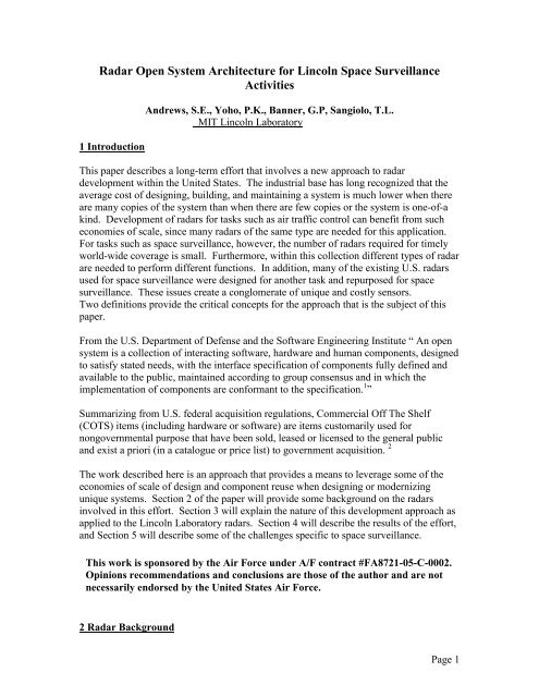
The Massachusetts Institute of Technology <strong>Lincoln</strong> Laboratory has extensive technicalinvolvement with two sets of radar systems supporting space surveillance activities.<strong>Lincoln</strong> conducts research and development on these sensors, developing both newhardware and signal processing techniques to improve capabilities. While all of the radarsare mechanical dish systems, they each have unique functions and operations.Haystack<strong>Radar</strong>HaystackAuxiliary <strong>Radar</strong>~ 1 kmMillstone Hill<strong>Radar</strong>Figure 1: <strong>Lincoln</strong> <strong>Space</strong> <strong>Surveillance</strong> Complex 3The first set of radars is located at the <strong>Lincoln</strong> <strong>Space</strong> <strong>Surveillance</strong> Complex inMassachusetts, approximately 25 miles west of Boston. <strong>Lincoln</strong> operates these radars aspart of the U.S. <strong>Space</strong> <strong>Surveillance</strong> Network. Figure 1 shows the site.Three of the radars at this site are the primary ones involved in space surveillance, theMillstone Hill <strong>Radar</strong>, the Haystack Long Range Imaging <strong>Radar</strong>, and the HaystackAuxiliary <strong>Radar</strong> (HAX). Millstone operates at L-band (1295 MHz), Haystack at X-band(10 GHz), and HAX at Ku-band (16.7 GHz). The differences in center frequencies fromone radar to another are just one example of the ways in which these radars are distinctfrom one another. Dish size and mount characteristics are other examples of physicaldifferences. In addition, their functions and operations are different. Millstone isprimarily used <strong>for</strong> tracking of deep space objects and collection of positional data. It alsorecords radar cross section (RCS) as a function of time <strong>for</strong> objects being tracked.Haystack and HAX are high-bandwidth radars used <strong>for</strong> range-Doppler imaging. ThisPage 2
equires very different signal characteristics and processing from typical trackingoperations. 4The second set of radars is located in the Kwajalein Atoll of the Republic of the MarshallIslands. These radars also operate <strong>for</strong> the U.S. <strong>Space</strong> <strong>Surveillance</strong> Network. TheALTAIR radar operates at both UHF and VHF frequencies and is primarily used <strong>for</strong>tracking objects in both near Earth and deep space orbits. It also collects RCS data.TRADEX operates in both L-band and S-band frequencies, also tracking objects in bothnear Earth and deep space. ALCOR is a C-band radar primarily used <strong>for</strong> range-Dopplerimaging and MMW is a millimeter-wave radar also used <strong>for</strong> range-Doppler imaging. 6Photographs of these radars are shown in Figure 2.Initial operational dates <strong>for</strong> these seven radars range from the 1960’s to the 1980’s 7,8 .Each of the radars has gone through numerous replacements of major components andupgrades, but these activities were handled independently, on a radar-by-radar basis, untilthe 1990’s. This means that maintenance activities <strong>for</strong> each radar were different,different spare parts were needed even <strong>for</strong> the same function on different radars, anddifferent computing hardware and software were used <strong>for</strong> similar functions on thedifferent radars. 8ALTAIRVHF, 158 MHz / UHF, 422MHzTRADEXL-band, 1320 MHzS-band, 2950 MHzMMWKa-band, 35 GHzW-band, 95 GHzALCORC-band, 5664 MHz<strong>Space</strong> <strong>Surveillance</strong> HubFigure 2: <strong>Radar</strong>s on Kwajalein Atoll6. Balesteri [2000]3 Motivation, Objectives and Development ApproachThe concept <strong>for</strong> the recent modernization ef<strong>for</strong>t was to use an open systems approach as ameans to reduce combined development time <strong>for</strong> modernization activities conducted onall of the radars, recognizing that this would lengthen the time to complete modernizationof the first radar in the series. This approach was also intended to carry over todevelopment of new systems. By using common components, maintenance costs could bereduced by sharing of spare parts and reduction in the number of distinct areas requiringseparate training. Finally, the goal of increasing commonality drove a process ofidentifying ways to take complex functions that were different in their specific nature <strong>for</strong>different radars (e.g., signal generation, signal processing) and generalizing them to beflexible functions with specific functions defined by software parameters or hardwaretuning. Use of these general, flexible components provides greater flexibility <strong>for</strong>individual systems, allowing tuning of operations based on situations to increaseper<strong>for</strong>mance.Page 3
In an open systems architecture, the radar functionality is decomposed into buildingblocks that are distinct and isolated, as shown in Figure 4. Interfaces are well-definedand not proprietary. This allows <strong>for</strong> independent development of the block components,as well as the option to upgrade the components separately, as long as the same interfacescan be used. Industry standard COTS hardware and interfaces are used, as possible,moving that portion of the development ef<strong>for</strong>t to system engineering tasks. Newcomponents developed by or <strong>for</strong> the <strong>Radar</strong> <strong>Open</strong> <strong>System</strong> <strong>Architecture</strong> (ROSA) would bedeveloped to work with the standard interfaces and COTS hardware, making themcandidates <strong>for</strong> technology transfer with multiple applications.Figure 5 shows a block diagram of the new ROSA architecture <strong>for</strong> the <strong>Lincoln</strong>Laboratory space surveillance radars. The components in gray are new and part ofROSA. The blue components are legacy and specific to the individual radars.Origin2000COTSSilicon GraphicsOrigin2000Silicon GraphicsTimingAntenna TransmitterMain Computerand RecordingFigure 4: Basic radar open system architecture decomposition 4Subsystems are designed in a way that allows <strong>for</strong> as much commonality with othersubsystems as possible while allowing <strong>for</strong> the per<strong>for</strong>mance of distinct functions. Atypical subsystem has two parts, as illustrated in Figure 6. One has hardware common totypical subsystems (shown in green) and one has hardware specific to the subsystem task(shown in yellow). On the common side, there is a hardware core with a centralprocessing unit, a network interface, interface <strong>for</strong> a time standard (IRIG), and COTSinterface hardware <strong>for</strong> communications between hardware units. These use VME/VXI,PCI and other IEEE standard technology. Subsystem dependent functions are also basedon VME boards. The system uses a POSIX-compliant operating system, and the centralprocessing unit includes built-in diagnostics <strong>for</strong> the subsystem. Figure 7 shows a COTSVME chassis with the COTS standard board set installed.Page 5
ROSAFrequencyand TimingRadiationMonitor InterfaceMICROWAVETransmitteTransmitterrRF IFRF Receiv IFerReceiverUpconverteUpconverterrTransmitteTransmitterrControlControlMaster TMaster TimingWFGWFGDigitalDigitalPulsePulseCompressionCompressionMainComputerLocalConsoleAntennaControlRecordingRecordingROSALegacySignature <strong>Radar</strong>Figure 5: ROSA block diagram 4RemoteDevelopmentand DiagnosticsENETCPUNetworkPCINetIRIGTODIRIGPower SupplyMonitorIPcarrierVME- BUSBoard 1Board 2Board3Board NCOTS/CommonSubsystem Dependent Boards<strong>System</strong> SpecificFigure 6: Generic subsystem block diagram 5Page 6
Figure 7: VME chassis and standard board set 54 Development Ef<strong>for</strong>t ResultsModernization was completed first on the radars at Kwajalein. At completion, there wasan 80% reduction in custom hardware, and now over 85% of the radar back-end hardwareis COTS. Only seven custom boards are needed <strong>for</strong> each radar. The ROSA architectureallows <strong>for</strong> automation of operations and diagnostics and also <strong>for</strong> potential remoting ofthose functions. Engineers working with these systems have also seen a dramaticincrease in flexibility, including features such as easy addition of new wave<strong>for</strong>ms <strong>for</strong> theradars.A significant part of the ef<strong>for</strong>t in the <strong>Lincoln</strong> Laboratory implementation of the opensystems architecture was in the development of a common real-time software program <strong>for</strong>operating the radars. Previously, the only two radars with common operating softwarewere the Haystack and HAX systems, which per<strong>for</strong>med similar functions. By creatingcommon software <strong>for</strong> operation of all of the radars, there was a 70% reduction in lines ofcode and 85% reduction in the number of languages, the number of operating systems,and the number of plat<strong>for</strong>ms. This greatly improves the maintainability of the softwareand also supports easier transition of new algorithms from one radar system to another. 4Other benefits were also realized. The new radar software supports over 150 wave<strong>for</strong>msand sixteen channels of coherent integration and detection. Operations can be conductedusing scripts that automate many of the functions. The software can also support digitalsimulation of satellite engagements at a full pulse-repetition rate. It supports multi-targettracking and can lay simulated objects over real data. 4Based on actual experience with both initial implementation and update, the team verifiedthe theory that the ROSA concept would result in reduced development time, and wehave already seen a reduction in maintenance costs. Because the architecture fosteredmodular components, design and development was decomposed into well-defined pieces.This allowed <strong>for</strong> use of numerous small development teams working to well-definedspecifications and interfaces. In addition, it allowed <strong>for</strong> more concurrent integration, test,and evaluation than more monolithic architectures. 4Page 7
The new architecture has also makes it easier to add or share components, and migrationto new technology can now be done at the component level. Engineers can test newdevelopment concepts with working components, reducing non-recovered engineeringcosts and leading to a better acquisition model. Specific radar functions are encapsulatedinto subsystems that hide the underlying hardware and software. Higher-level tasks canbe specified at a functional level and the subsystems determine how the specific radarexecutes them. 4The key to the architecture is the communications between components, including thedefinition of interfaces and messages. These allow <strong>for</strong> the common concepts to betranslated into radar-specific implementation and <strong>for</strong> the radar actions and data to betranslated and passed back through appropriate channels.5 <strong>Space</strong> <strong>Surveillance</strong><strong>Space</strong> surveillance has a set of tasks that are distinct from other common radar tasks. Thecapability to per<strong>for</strong>m these tasks had to be incorporated into ROSA <strong>for</strong> the <strong>Lincoln</strong>sensors. Some of these key tasks are summarized in the following paragraphs.User Interface: For tracking satellites, operators are interested in factors such as how wellthe currently measured position matches the predicted orbit. Other in<strong>for</strong>mation useful <strong>for</strong>pushing radar technology is of less use <strong>for</strong> conducting space surveillance operations. Partof the ROSA development was to include displays tailored <strong>for</strong> space surveillanceapplications. 4Mean Anomaly Search: Mechanically steered radars do not have the advantage ofelectronically steered radars <strong>for</strong> sweeping out large swaths of orbital space. This limitssearch capabilities. Fortunately, <strong>for</strong> an object whose approximate orbit is known, it ispossible to limit the search space. It is much easier to change an orbit’s altitude than itsplane, and small changes in altitude look much like changes in changes in mean anomaly.Because of this combination of factors, the heritage systems had built in capability tosearch along an orbit in mean anomaly (the satellite trajectory) 3 . These search patternswere built into the functionality of ROSA.Processing of Multiple Polarization Returns: One of the key heritage features of theseresearch and development radars has been the ability to record returns in the differentsenses of polarization. One of the past benefits realized from this additional in<strong>for</strong>mationhas been the ability to improve the effective sensitivity of the radars <strong>for</strong> deep spacetracking. 4Debris Mode: In the debris mode, the radar stares at a fixed azimuth and elevation andrecords amplitude, beam position, range, and Doppler as objects pass through. Thesedata are converted to position and radar cross-section in<strong>for</strong>mation to help estimate debrispopulation. 4Page 8
Deep <strong>Space</strong> Tracking: Millstone, Haystack, ALTAIR, and TRADEX have a long heritageof being able to track objects in orbits with periods longer then 225 minutes (referred toas “deep space” in our space surveillance lingo), with geostationary orbits being a classof orbits frequently tracked. Due to differences in the signal processing architecturebetween the legacy and ROSA systems, developing an equivalent deep space capabilityin ROSA was a significant ef<strong>for</strong>t. Background and some details of this processing areprovided in the following paragraphs. 7Signal processing techniques <strong>for</strong> tracking objects in orbits as distant as geostationaryorbits were adapted from astronomy techniques. In the early 1960s, basic techniqueswere applied to data after open-loop tracking of a target to detect the target in the data. Inthe mid-1960s, algorithms were implemented on a real-time computer to allowrudimentary multi-pulse processing in real-time. In the early 1970s, the Haystackplanetary radar was able to observe geostationary satellites. This capability wastransitioned to the Millstone Hill <strong>Radar</strong>, which began routine closed-loop trackingoperations of deep space objects <strong>for</strong> the U.S. <strong>Space</strong> <strong>Surveillance</strong> Network in 1975. 7The process requires a radar to operate beyond its unambiguous range. Because therange-to-the-fourth-power loss is enormous at geostationary ranges (on the order of 64dB below returned signal <strong>for</strong> object at 1000 km range), every opportunity to enhance theeffective sensitivity is important. One step is to integrate on the order of 1000 pulsesfrom the signal returns, which can buy as much as 30 dB. 6 Un<strong>for</strong>tunately, variations intarget characteristics mean that such a gain can not be achieved with the basic <strong>for</strong>m ofintegration. Different target types require different assumptions <strong>for</strong> the integrationprocess. Engineers at <strong>Lincoln</strong> Laboratory found that by simultaneously processing thedata according to twelve different signal models and then selecting the best, the effectivesensitivity could be improved over simply assuming one model. 7 These models aresummarized in Figure 8.The first division of satellite characteristics is the nature of their frequency spectrum. Ifthe spectrum is very narrow, then the satellite does not have much rotational motion andis considered to be “coherent”. This is the best case <strong>for</strong> integration, since it allows <strong>for</strong> thebest accumulation of signal across multiple pulses. If the spectrum is more like a multilinespectrum, the target is considered to be “quasi-coherent”. This is not as beneficial asa narrow spectrum, but is better <strong>for</strong> integration than one in which the energy is spreadacross a range of frequencies.Page 9
Three possibletarget spectraCoherent Quasi-coherent Noncoherent| FFT | 2Narrowspectrum| FFT | 2Linespectrum| FFT | 2Widespectrum–20 0 20–20 0 20–20 0 20Frequency(Hz) Frequency(Hz) Frequency (Hz)Four possiblereceive polarization characteristicsLeft only Right only Joint Polarimetric<strong>Radar</strong> crosssection (dBsm)151050LR5L55R00015151510R10L10Time Time Time TimeLRFigure 8 Diagram showing a subset of the Target models used in Deep <strong>Space</strong> Tracking. 7The other division in satellite characteristics is the polarization of the returned signal. The<strong>Lincoln</strong> radars all transmit in right circular polarization. For a radar transmitting acircular polarization, a sphere returns a signal in the opposite sense. If the radar pulsetakes two bounces be<strong>for</strong>e returning, then the original polarization is returned. A complextarget may result in an apparently random mix of polarizations. Certain targets may havereturns with strongly correlated polarizations.By processing the signal returns under each of the twelve combinations of assumptions,the signal processing algorithms are able to pull more out of the signal than if the signalprocessor worked only according to one set of assumptions and had mis-matched targettypes. As mentioned previously, the incoming signal is processed simultaneouslythrough each of the models, and the best one is selected <strong>for</strong> use in tracking. 6Remote Operations: One of the benefits of the ROSA architecture is that it enabled thedevelopment of a remote operations capability. As part of an additional developmentef<strong>for</strong>t, a high-speed network was established that permits transmission of radar data to aseparate location in near real time, as well as bringing commanding in<strong>for</strong>mation back tothe main computer.Figure 9 shows a block diagram of the wideband network with the Haystack and HAXradars illustrated. Items in green are those involving hardware related to the widebandPage 10
network system (WNS). Components that reside at the radar site are clearly identified.The operators sit at the main laboratory facility, approximately 20 miles from the site,and receive radar data and make decisions based on that data in real time.MICROWAVETransmitterReceiverMICROWAVETransmitterReceiverFigure 9: Block diagram of wideband communications network 4Now, instead of radar operations being run directly from command stations located ateach radar site, all of the radars can be run from one central facility. Currently, Haystack,HAX, and Millstone are all run from a single control room located 20 miles from theradars, shown in Figure 10. In addition, personnel in this control room can monitor theradars at Kwajalein and receive data from them in near-real time. 3There are multiple benefits to this centralization of control and increased access to realtimesensor in<strong>for</strong>mation: Operators can view other sensor activities real-time There is direct communications among sensor operators Routine access to operator screens <strong>for</strong> sensors enhances cross-sensorfamiliarity 3This is particularly useful in a complex tracking case such as a many-payload launch, (<strong>for</strong>example, one where many experimental microsatellites are deployed). The commonalityand messaging enabled by the ROSA architecture allow <strong>for</strong> easy hand-off of data fromone sensor to another. The shared operations center allows operators to workcollaboratively without being limited to telephones. A picture is worth 1000 words, andnow each operator can easily see the other operators’ screens in real time. 3Page 11
Figure 10 Control room <strong>for</strong> LSSC <strong>Radar</strong>s 36 Summary<strong>Lincoln</strong> Laboratory embarked on an ef<strong>for</strong>t to modernize the radars used <strong>for</strong> spacesurveillance following a novel concept. The success of the modernization process alongwith gains seen in maintenance and operations has validated the promises that an openarchitecture would reduce the time and cost of development and operations. This wasaccomplished through the following activities; making efficient use of engineeringresources, abstracting the hardware layer from the software and allowing each to beworked independently, and use of portable building blocks that could be used in multipleplaces.ROSA has been implemented in several large radar development and modernizationprograms, including radars at the Kwajalein Missile Range, the <strong>Lincoln</strong> <strong>Space</strong><strong>Surveillance</strong> Complex, and others not discussed in this paper.The development team believes that there is a strong case <strong>for</strong> migration of ROSAcomponents to industry. Technology transfer is much more efficient at the componentlevel than the system level – this is seen with plug-and-play components of computers.In fact, future radar development could start with existing plug and play componentsfrom the commercial marketplace.Bibliography1. Software Engineering Institute, Carnegie Mellon Institute, 2009,http://www.sei.cmu.edu/opensystems/2. Federal Acquisition Regulation, General Services Administrationhttp://www.acquisition.gov/far/current/html/Subpart%202_1.html#wp1145507,17 Feb 2009.Page 12
3. Andrews, S.E., Bougas, W. C., Cott, T.A., Hunt, S. M., Kadish, J.M., Solodyna,C.V., “Enhancing Multi-payload Launch Support with Netcentric Operations”,7th US/Russian <strong>Space</strong> <strong>Surveillance</strong> Workshop, October 29 – November 2, 20074. Sangiolo, Thomas L., “<strong>Radar</strong> <strong>Open</strong> <strong>System</strong> <strong>Architecture</strong> For The <strong>Lincoln</strong> <strong>Space</strong><strong>Surveillance</strong> Complex (LSSC)”, Proceedings of the 2001 <strong>Space</strong> ControlConference, MIT <strong>Lincoln</strong> Laboratory, 3-5 April, 2001, STK-256, S.E. AndrewsEd5. Sangiolo, Thomas L., “<strong>Radar</strong> <strong>Open</strong> <strong>System</strong> <strong>Architecture</strong> For The <strong>Lincoln</strong> <strong>Space</strong><strong>Surveillance</strong> Complex (LSSC)”, Proceedings of the 2000 <strong>Space</strong> ControlConference, MIT <strong>Lincoln</strong> Laboratory, 11-13 April, 2000, STK-255, S.E. AndrewsEd6. Balesteri, D., Baldassini, J., DeCoster, W., Hogan, G., Hunt, S., Lazdowski, K.,and Mathwig, J. “Kwajalein <strong>Space</strong> <strong>Surveillance</strong> Center (KSSC), 2000 <strong>Space</strong>Control Conference, MIT <strong>Lincoln</strong> Laboratory, 12 April 20007. Stone, M.L. and Banner, G.P, <strong>Radar</strong>s <strong>for</strong> the Detection and Tracking of BallisticMissiles, Satellites, and Planets, <strong>Lincoln</strong> Laboratory Journal, pp 217-244, Vol 12,Number 2, 20008. Camp, W.W., Mayhan, J.T. and O’Donnell, R. M., “Wideband <strong>Radar</strong> <strong>for</strong>Ballistic Missile Defense and Range-Doppler Imaging of Satellites” <strong>Lincoln</strong>Laboratory Journal, pp 267-280, Vol 12, Number 2, 20009. Banner, G.P. “Deep space surveillance – overview and radar tracking”, 3rdUS/Russian <strong>Space</strong> <strong>Surveillance</strong> Workshop, 20-23 October 1998,Page 13