

Iss26 Art2 - Local Ice Chrushing Analysis of Pile Wall.pdf - Plaxis
Iss26 Art2 - Local Ice Chrushing Analysis of Pile Wall.pdf - Plaxis
Iss26 Art2 - Local Ice Chrushing Analysis of Pile Wall.pdf - Plaxis
- No tags were found...

Create successful ePaper yourself
Turn your PDF publications into a flip-book with our unique Google optimized e-Paper software.
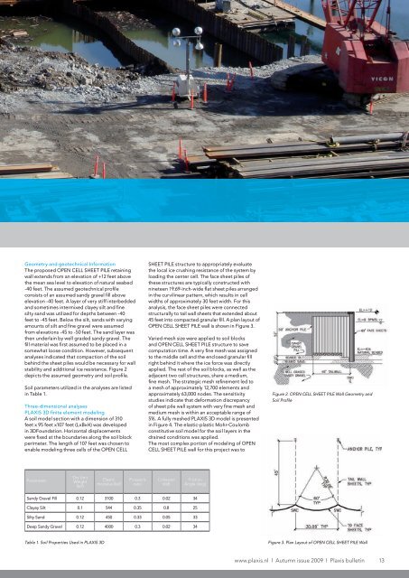
Geometry and geotechnical InformationThe proposed OPEN CELL SHEET PILE retainingwall extends from an elevation <strong>of</strong> +12 feet abovethe mean sea level to elevation <strong>of</strong> natural seabed-40 feet. The assumed geotechnical pr<strong>of</strong>ileconsists <strong>of</strong> an assumed sandy gravel fill aboveelevation -40 feet. A layer <strong>of</strong> very stiff interbeddedand sometimes intermixed clayey silt and finesilty sand was utilized for depths between -40feet to -45 feet. Below the silt, sands with varyingamounts <strong>of</strong> silt and fine gravel were assumedfrom elevations -45 to -50 feet. The sand layer wasthen underlain by well graded sandy gravel. Thefill material was first assumed to be placed in asomewhat loose condition. However, subsequentanalyses indicated that compaction <strong>of</strong> the soilbehind the sheet piles would be necessary for wallstability and additional ice resistance. Figure 2depicts the assumed geometry and soil pr<strong>of</strong>ile.Soil parameters utilized in the analyses are listedin Table 1.Three-dimensional analysesPLAXIS 3D finite element modelingA soil model section with a dimension <strong>of</strong> 310feet x 95 feet x107 feet (LxBxH) was developedin 3DFoundation. Horizontal displacementswere fi xed at the boundaries along the soil blockperimeter. The length <strong>of</strong> 107 feet was chosen toenable modeling three cells <strong>of</strong> the OPEN CELLSHEET PILE structure to appropriately evaluatethe local ice crushing resistance <strong>of</strong> the system byloading the center cell. The face sheet piles <strong>of</strong>these structures are typically constructed withnineteen 19.69-inch-wide flat sheet piles arrangedin the curvilinear pattern, which results in cellwidths <strong>of</strong> approximately 30 feet width. For thisanalysis, the face sheet piles were connectedstructurally to tail wall sheets that extended about45 feet into compacted granular fill. A plan layout <strong>of</strong>OPEN CELL SHEET PILE wall is shown in Figure 3.Varied mesh size were applied to soil blocksand OPEN CELL SHEET PILE structure to savecomputation time. A very fine mesh was assignedto the middle cell and the enclosed granular fillright behind it where the ice force was directlyapplied. The rest <strong>of</strong> the soil blocks, as well as theadjacent two cell structures, share a medium,fine mesh. The strategic mesh refinement led toa mesh <strong>of</strong> approximately 12,700 elements andapproximately 63,000 nodes. The sensitivitystudies indicate that deformation discrepancy<strong>of</strong> sheet pile wall system with very fine mesh andmedium mesh is within an acceptable range <strong>of</strong>5%. A fully meshed PLAXIS 3D model is presentedin Figure 4. The elastic-plastic Mohr-Coulombconstitutive soil model for the soil layers in thedrained conditions was applied.The most complex portion <strong>of</strong> modeling <strong>of</strong> OPENCELL SHEET PILE wall for this project was toFigure 2. OPEN CELL SHEET PILE <strong>Wall</strong> Geometry andSoil Pr<strong>of</strong>ileParameterDry UnitWeight(kcf)Elasticmodulus (ksf)Poisson’sratioCohesion(ksf)FrictionAngle (deg)Sandy Gravel Fill 0.12 3100 0.3 0.02 34Clayey Silt 0.1 544 0.35 0.8 25Silty Sand 0.12 450 0.33 0.05 33Deep Sandy Gravel 0.12 4000 0.3 0.02 34Table 1. Soil Properties Used in PLAXIS 3DFigure 3. Plan Layout <strong>of</strong> OPEN CELL SHEET PILE <strong>Wall</strong>www.plaxis.nl l Autumn issue 2009 l <strong>Plaxis</strong> bulletin 13


