

Iss26 Art2 - Local Ice Chrushing Analysis of Pile Wall.pdf - Plaxis
Iss26 Art2 - Local Ice Chrushing Analysis of Pile Wall.pdf - Plaxis
Iss26 Art2 - Local Ice Chrushing Analysis of Pile Wall.pdf - Plaxis
- No tags were found...

Create successful ePaper yourself
Turn your PDF publications into a flip-book with our unique Google optimized e-Paper software.
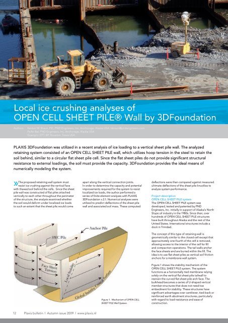
<strong>Local</strong> ice crushing analyses <strong>of</strong>OPEN CELL SHEETPILE OPEN ® <strong>Wall</strong> CELL by SHEET 3DFoundationPILE® <strong>Wall</strong> by 3DFoundationAuthors:Kenton W. Braun, P.E., PND Engineers, Inc, Anchorage, Alaska USA, kbraun@pndengineers.comFeifei Bai, PND Engineers, Inc, Anchorage, Alaska USAGuang Li, EPT, BP, Houston, Texas USAPLAXIS 3DFoundation was utilized in a recent analysis <strong>of</strong> ice loading to a vertical sheet pile wall. The analyzedretaining system consisted <strong>of</strong> an OPEN CELL SHEET PILE wall, which utilizes hoop tension in the steel to retain thesoil behind, similar to a circular flat sheet pile cell. Since the flat sheet piles do not provide significant structuralresistance to external loadings, the soil must provide the capacity. 3DFoundation provides the ideal means <strong>of</strong>numerically modeling the system.»The proposed retaining wall system mustresist ice crushing against the vertical facewith thawed soil behind the cells. Since the sheetpile wall was constructed <strong>of</strong> flat piles attachedvertically to each other throughout the perimeter<strong>of</strong> the structure, the analysis examined whetherthe soil would deform under localized ice loadsto such an extent that the sheet pile would comeapart along the vertical connection joints.In order to determine the capacity and potentialimprovements required for the system to resistlocalized ice loads, the author performed aseries <strong>of</strong> finite element analyses with PLAXIS3DFoundation v.2.1. Numerical analyses wereutilized to predict deflections <strong>of</strong> the sheet pilewall and associated soil mass. These computeddeflections were then compared against measuredultimate deflections <strong>of</strong> the sheet pile knuckles toanalyze system performance.Project descriptionOPEN CELL SHEET PILE systemThe OPEN CELL SHEET PILE system wasdeveloped, tested and patented by PNDEngineers, Inc. initially in support <strong>of</strong> Alaska’s NorthSlope oil industry in the 1980s. Since then, overhundreds <strong>of</strong> OPEN CELL SHEET PILE structureshave built throughout Alaska and the rest <strong>of</strong> theUnited States. International structures include adock in Trinidad.The concept <strong>of</strong> this type <strong>of</strong> retaining wall isgeometrically similar to the closed cell except thatapproximately one-fourth <strong>of</strong> the cell is removed,allowing access to the interior <strong>of</strong> the cell for filland compaction operations. The tail walls anchorthe face sheets and are buried within the fill. Theidea is to use flat sheet piles as vertical soil frictionanchors for a membrane wall system.Figure 1. Mechanism <strong>of</strong> OPEN CELLSHEET PILE <strong>Wall</strong> SystemFigure 1 shows the stability mechanism <strong>of</strong> theOPEN CELL SHEET PILE system. The systemfunctions as a horizontally tied membrane relyingsolely on the vertical flat sheet pile tailwall torestrain the curved flat sheet pile arch face. Thebulkhead becomes a series <strong>of</strong> U-shaped verticalmember structures that does not need toeembedment for stability. These structures havesignificant advantages over cantilever, tied-back orreinforced earth abutment structures, particularlywith regard to load resistance and ease <strong>of</strong>construction.12 <strong>Plaxis</strong> bulletin l Autumn issue 2009 l www.plaxis.nl
Geometry and geotechnical InformationThe proposed OPEN CELL SHEET PILE retainingwall extends from an elevation <strong>of</strong> +12 feet abovethe mean sea level to elevation <strong>of</strong> natural seabed-40 feet. The assumed geotechnical pr<strong>of</strong>ileconsists <strong>of</strong> an assumed sandy gravel fill aboveelevation -40 feet. A layer <strong>of</strong> very stiff interbeddedand sometimes intermixed clayey silt and finesilty sand was utilized for depths between -40feet to -45 feet. Below the silt, sands with varyingamounts <strong>of</strong> silt and fine gravel were assumedfrom elevations -45 to -50 feet. The sand layer wasthen underlain by well graded sandy gravel. Thefill material was first assumed to be placed in asomewhat loose condition. However, subsequentanalyses indicated that compaction <strong>of</strong> the soilbehind the sheet piles would be necessary for wallstability and additional ice resistance. Figure 2depicts the assumed geometry and soil pr<strong>of</strong>ile.Soil parameters utilized in the analyses are listedin Table 1.Three-dimensional analysesPLAXIS 3D finite element modelingA soil model section with a dimension <strong>of</strong> 310feet x 95 feet x107 feet (LxBxH) was developedin 3DFoundation. Horizontal displacementswere fi xed at the boundaries along the soil blockperimeter. The length <strong>of</strong> 107 feet was chosen toenable modeling three cells <strong>of</strong> the OPEN CELLSHEET PILE structure to appropriately evaluatethe local ice crushing resistance <strong>of</strong> the system byloading the center cell. The face sheet piles <strong>of</strong>these structures are typically constructed withnineteen 19.69-inch-wide flat sheet piles arrangedin the curvilinear pattern, which results in cellwidths <strong>of</strong> approximately 30 feet width. For thisanalysis, the face sheet piles were connectedstructurally to tail wall sheets that extended about45 feet into compacted granular fill. A plan layout <strong>of</strong>OPEN CELL SHEET PILE wall is shown in Figure 3.Varied mesh size were applied to soil blocksand OPEN CELL SHEET PILE structure to savecomputation time. A very fine mesh was assignedto the middle cell and the enclosed granular fillright behind it where the ice force was directlyapplied. The rest <strong>of</strong> the soil blocks, as well as theadjacent two cell structures, share a medium,fine mesh. The strategic mesh refinement led toa mesh <strong>of</strong> approximately 12,700 elements andapproximately 63,000 nodes. The sensitivitystudies indicate that deformation discrepancy<strong>of</strong> sheet pile wall system with very fine mesh andmedium mesh is within an acceptable range <strong>of</strong>5%. A fully meshed PLAXIS 3D model is presentedin Figure 4. The elastic-plastic Mohr-Coulombconstitutive soil model for the soil layers in thedrained conditions was applied.The most complex portion <strong>of</strong> modeling <strong>of</strong> OPENCELL SHEET PILE wall for this project was toFigure 2. OPEN CELL SHEET PILE <strong>Wall</strong> Geometry andSoil Pr<strong>of</strong>ileParameterDry UnitWeight(kcf)Elasticmodulus (ksf)Poisson’sratioCohesion(ksf)FrictionAngle (deg)Sandy Gravel Fill 0.12 3100 0.3 0.02 34Clayey Silt 0.1 544 0.35 0.8 25Silty Sand 0.12 450 0.33 0.05 33Deep Sandy Gravel 0.12 4000 0.3 0.02 34Table 1. Soil Properties Used in PLAXIS 3DFigure 3. Plan Layout <strong>of</strong> OPEN CELL SHEET PILE <strong>Wall</strong>www.plaxis.nl l Autumn issue 2009 l <strong>Plaxis</strong> bulletin 13
<strong>Plaxis</strong> practice: Practice: Mohr-Coulomb <strong>Local</strong> ice crushing parameters analyses <strong>of</strong> for OPEN modelling CELL <strong>of</strong> SHEET concrete PILE® structures <strong>Wall</strong> by 3DFoundationappropriately model the steel wall, especiallythe contiguous sheet piles vertically attachedvia interlocks. During an ice event, an interlockconnection will first freely rotate around thevertical axis when an inward out-<strong>of</strong>-plane load isapplied. Under an increasing load, the interlockswill first straighten, followed by continued inwarddeflection. Eventually, the pile interlocks willbind and begin to resist load until, ultimately, theinterlock pries apart.The inappropriate application <strong>of</strong> isotropicsteel properties could result in an extremelyunconservative behavior whereby, in the mostextreme condition <strong>of</strong> a solid steel plate, most<strong>of</strong> the ice loads could be carried by the OPENCELL ® structure rather than the enclosed soilbody. Consequently, a series <strong>of</strong> fully decouplednonlinear force strain (i.e. axial force-axial strain)or moment-curvature (i.e. bending momentrotationcurvature) relations were developed.A bilinear force-strain relation (large in-planehorizontal tension vs. small in-plane horizontalcompression) was also applied to appropriatelyestimate the axial hoop tension in steel wall. Thebending moment-rotation curvature to define ahinge property caused by interlock rotation wasderived and applied to the model based on thedestructive sheet pile testing performed by theauthor. Full sheet pile section properties havebeen assigned to the sides <strong>of</strong> model (boundary).Considering the large dimension betweenadjacent OPEN CELL ® structures and the localice pressure that is only applied to the center <strong>of</strong>middle cell, the effects <strong>of</strong> the boundary cell (sides<strong>of</strong> the model) is neglected.Loading conditionsThe localized ice crushing force was set up asstatic ice pressure in <strong>Plaxis</strong> following the localpressure-area curves identified in Table 2. Fromelevation +2 feet to -10 feet, ISO 19906 criteriawere utilized considering this area could beexposed to confined ice with large compressivepressure. Above elevation +2, the ice wouldtypically be rubbled and ice pressure is thereforegreatly reduced. Similarly, ice located belowelevation -10 would generally be weaker andwould not experience the confinement necessaryfor large local loads. Therefore, lower compressivepressures were utilized for the upper and lower icecrushing zones.For modeling purposes, the ice load was appliedat the highest elevation within each boundaryconsidering that this location would have theminimum soil mass behind the sheet pile to resistthe crushing force.Failure criteriaDevelopment <strong>of</strong> failure criteria for the analyzedstructure presented a significant challenge to theproject. Considering the extreme nature <strong>of</strong> theice loads, plastic soil movement behind the sheetpiles was acceptable, as long as the sheet pilesdid not come apart. The bilinear behavior <strong>of</strong> theinterlock hinges (as well as modeling limitations)also made it difficult to utilize structural stresseswithin the steel as an evaluation method.Ultimately, it was determined that the bestmeasure <strong>of</strong> structure limit state was to examinethe amount <strong>of</strong> rotation at the interlocks. The anglebetween adjacent sheet piles right before failurewas defined as ultimate deflection angle. Thisdeflection angle was derived from destructivesheet pile testing which indicated a 20 degreerelative angle (between adjacent sheet piles) couldbe utilized as the failure criteria when evaluatingthe <strong>Plaxis</strong> results. A depiction <strong>of</strong> this criteria andthe associated angle is presented in Figure 5.It should be noted that there is likely much morereserve capacity in the sheet piles than that whichwas utilized in the modeling effort. The ultimatetesting proved to be difficult in that plasticbending <strong>of</strong> the sheet piles generally occurredsooner than ultimate failure <strong>of</strong> the knuckles. Suchresults indicate that the sheet pile wall would likelybend and form plastic hinges prior to knucklefailure, which would allow for much greaterdeflections and load absorption/distribution thanthat utilized in this analysis.Figure 5. Sheet <strong>Pile</strong> Failure Criteria DiagramFigure 4. Meshed 3D PLAXIS Model14 <strong>Plaxis</strong> bulletin l Autumn issue 2009 l www.plaxis.nl
<strong>Plaxis</strong> Practice: Mohr-Coulomb parameters for modelling <strong>of</strong> concrete structures<strong>Plaxis</strong> practice: <strong>Local</strong> ice crushing analyses <strong>of</strong> OPEN CELL SHEET PILE® <strong>Wall</strong> by 3DFoundationInitial Analyses ResultsThe initial ice crushing analyses results arepresented in Table 3. Results are organizedcorresponding to the varied ice contact areas andloading elevations defined in Table 2. The boldnumbers indicate the relative deflection anglebetween adjacent sheet piles exceeds the ultimatedeflection angle criteria <strong>of</strong> 20 degrees.Crushing <strong>Ice</strong>Contact AreaCrushing LoadElevation (feet)Assumed <strong>Ice</strong> CrushingPressure (psi)2 ft 2 +2 to -10 3500+4.5 to +2 400-10 to -39 300Table 2. <strong>Ice</strong> Loading Conditionsin <strong>Plaxis</strong>Selected deformation contours <strong>of</strong> the enclosedgravel fill and OPEN CELL SHEET PILE wall are alsoshown in Figure 6. In Figure 7, the total incrementalsoil deflection contour (|u|) presents a very distinctfailure surface in the soil block at the loaded area.The analyzed sheet pile deflections <strong>of</strong> thenineteen pile segments are presented in Figure8. The deflection <strong>of</strong> sheet pile along various wallelevations are plotted separately. The vertical axisrepresents the X coordinates (unit in feet) to locateeach sheet pile segment in PLAXIS 3D. The plotsalso indicate the maximum pile deflection occurswithin the range <strong>of</strong> elevation +4 feet to elevation-6 feet, where 100 ft 2 crushing ice was loaded.Soil ReinforcementInitial numerical analysis (Table 3) indicated thatthawed fill soil and sheet piles alone were notsufficient to resist the local ice pressure at thehigher elevations. Thus, soil improvement wasrecommended within this zone and the preliminarydesign assumed jet grouting was utilized forthis purpose. A revised <strong>Plaxis</strong> model was thendeveloped assuming the grouted columns wereinstalled from approximately 8 feet below gradeto 23 feet below grade, stiffening approximately15 feet <strong>of</strong> soil at the face <strong>of</strong> the sheet piles. Theinitial cohesion c and friction angle { for jetgrouting was assumed to be 22 ksf and zero10 ft 2 +2 to -10 1130+4.5 to +2 300UnfrozenSandyGravel-10 to -39 200100 ft 2 +2 to -10 225+4.5 to +2 200-10 to -39 100Calculation CaseMax Horizontal Def.<strong>of</strong> Soil (in)Max Relative RotationAngle (deg)400 psi @ 2 ft 2 0.5 3.73500 psi @ 2 ft 2 31.0 40.0300 psi @ 2 ft 2 0.3 negligible300 psi @ 10 ft 2 16.0 28.01130 psi @ 10 ft 2 57.0 78.0200 psi @ 10 ft 2 0.5 negligible200 psi @ 100 ft 2 48.0 17.0225 psi @ 100 ft 2 32.0 13.0100 psi @ 100 ft 2 1.0 negligibleTable 3 Initial <strong>Ice</strong> Crushing Analyses Results SummaryFigure 6. Maximum Horizontal Deformation <strong>of</strong> Fill and OPEN CELL SHEET PILE at Failure(200 psi with 100 ft 2 contact area @ Elevation +4.5 feet)www.plaxis.nl l Autumn issue 2009 l <strong>Plaxis</strong> bulletin 15
<strong>Plaxis</strong> practice: <strong>Local</strong> ice crushing analyses <strong>of</strong> OPEN CELL SHEET PILE® <strong>Wall</strong> by 3DFoundation<strong>Plaxis</strong> Practice: Simulation <strong>of</strong> Soil Nail Structures using PLAXIS 2DFigure 7. Soil Failure Surface at Failure-Total Incremental Deformation (200 psi with 100 ft2 contact area @ Elevation +4.5 feet)degrees, respectively. Results from this revisedanalysis are presented in Table 4 and indicatedpositive behavior. Figure 9 also depicts the totalincremental soil deformation contours associatedwith the analysis.Discussion and conclusionsPLAXIS 3DFoundation provides a very usefultool for analyzing the performance <strong>of</strong> an OPENCELL SHEET PILE wall system under localizedice impact. The initial ice crushing analysesindicated that ice crushing loads on the sheetpile wall exceeded the strength capacity <strong>of</strong> thethawed granular fill soil and sheet piles alone.Subsequent analyses utilizing soil reinforcementwas found to provide greater resistance andstructural integrity within the failure zone andprovided positive results. Shear strain analysesin <strong>Plaxis</strong> showed that the proposed jet groutingsoilcrete could have some cracking develop underhigh crushing pressure between elevations +4.5feet to -10 feet. Considering the frequency <strong>of</strong>any anticipated ice loading events and that thestatic ice crushing analyses in <strong>Plaxis</strong> is relativelyconservative, the assumed width and depth <strong>of</strong> thejet grouting zone was believed to be adequate,but additional analyses may be required t<strong>of</strong>urther refine the design. For reinforced soil, therelative rotation angle <strong>of</strong> adjacent sheet pileswas reduced significantly with the use <strong>of</strong> soilreinforcement, resulting in a maximum value <strong>of</strong>6 degrees as compared to a 78 degree angle forthe unreinforced case. The very low result forreinforced soil indicates that jet grouting or othersimilar means could have voids yet still providesufficient resistance.Reinforced SoilCalculation CaseTable 4 Initial <strong>Ice</strong> Crushing Analyses Results SummaryMax Horizontal Def.<strong>of</strong> Soil (in)Max Relative RotationAngle (deg)400 psi @ 2 ft 2 0.4 3.53500 psi @ 2 ft 2 1.8 6.0300 psi @ 2 ft 2 0.1 negligible300 psi @ 10 ft 2 1.3 4.51130 psi @ 10 ft 2 1.7 5.0200 psi @ 10 ft 2 0.3 negligible200 psi @ 100 ft 2 1.6 3.5225 psi @ 100 ft 2 1.2 3.0100 psi @ 100 ft 2 0.8 negligible16 <strong>Plaxis</strong> bulletin l Autumn issue 2009 l www.plaxis.nl
<strong>Plaxis</strong> practice: <strong>Local</strong> ice crushing <strong>Plaxis</strong> analyses Practice: <strong>of</strong> Simulation OPEN CELL <strong>of</strong> Soil SHEET Nail PILE® Structures <strong>Wall</strong> by using 3DFoundation PLAXIS 2DAcknowledgementThis project is supported by BP Exploration(Alaska), Inc. Special thanks are also given to <strong>Plaxis</strong>bv, Hayward Baker, Inc and Geoengineers, Inc forproviding technical support to the analyses.References• Bowles J. “Foundation <strong>Analysis</strong> and Design”Fifth Edition, McGraw Hill (1996)• ISO/DIS 19906 Draft Standard for Petroleumand natural gas industries – Arctic Offshorestructures (November 2008)• <strong>Plaxis</strong> bv “3DFoundation User Manual” (2007)Figure 8. Perimeter Sheet <strong>Pile</strong> Deflection at Failure (200 psi with 100 ft 2 contact area @ Elevation +4.5 feet)Figure 9. Maximum Total Incremental Deformation <strong>of</strong> Reinforced Soil (200 psi with 100 ft 2 contact area @ Elevation +4.5 feet)www.plaxis.nl l Autumn issue 2009 l <strong>Plaxis</strong> bulletin 17


