MP-3724 - Jaycar Electronics
MP-3724 - Jaycar Electronics
MP-3724 - Jaycar Electronics
- No tags were found...

You also want an ePaper? Increase the reach of your titles
YUMPU automatically turns print PDFs into web optimized ePapers that Google loves.
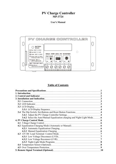
Precautions1. Before using the charge/load controller, read all the instructions and cautionary markings on thecharge/load controller, the batteries and the photovoltaic panels.2. Do not attempt to repair the controller. Incorrect re-assembly may result in a risk of electric shock orfire.3. To reduce risk of electric shock, disconnect all wiring before attempting any maintenance or cleaning.Turning off controls will not reduce this risk. PV panels produce power when exposed to light – coverthem with opaque material before servicing.4. Working in Vicinity of a Lead Acid Battery is dangerous. Batteries generate EXPLOSIVE gases duringnormal operation. Provide ventilation to outdoors from the highest point of the battery compartment.5. This charge/load controller is intended to be used with a battery supply of 24 VDC nominal voltage.6. Be extra cautious to reduce the possibility of dropping a metal tool onto batteries. It might spark orshort-circuit batteries or other electrical parts that may cause explosion. Cover wrench handles withplastic tape or vinyl dip coating material.SpecificationsModelsBattery voltageMaximum PV panel open circuit voltageContinuous load/charge currentMaximum charge current (5 mins)Maximum load current (5 mins)Operation current(no Load and no PV)<strong>MP</strong>-<strong>3724</strong>24V52V20A25A25A30mAVoltage across terminals (PV to Battery) 0.8VVoltage across terminals (Battery to Load) 0.4VElectronic Blocking(To protect against reverse polarity connection of PV panel and to blockcurrent from battery to PV panel when voltage of battery is higher than PVYespanel)Battery reverse polarity protectionYesOvercharge & Over-discharge protectionYesBattery status LED indication5-State LED IndicationsCharging status indication3-State LCD DisplayRecommended wire size#10AWGWeight0.47kgDimension (WxDxH)150 x 85 x 45 mmFuse30AOperating ambient temperature -10 to 50 °COver temperature protectionYesBattery charging float voltage settingAdjustable from 24.0-33.0VBattery charging bulk voltage settingAdjustable from 24.0-33.0VDC load control mode (For DC load terminal):Low Voltage Disconnect(LVD)Adjustable from 16.0-32.0VLow Voltage Reconnect(LVR)Adjustable from 16.0-32.0VP.1
3.3 LCD DisplayThe LCD Display shows the battery voltage, PV panel voltage and the charging modes duringnormal day time operation. At night time or low sunlight or PV disconnected situation, displayof PV VOLT value is to be ignored .LCD DISPLAYBATT VOLT.................PV VOLT.......................PV CURR......................TOD PV_AH.................L1D PV_AH..................L2D PV_AH..................Charging StatusBULK CHARGE...........ABSORB CHARGE......FLOAT CHARGE.........EQULIZ CHARGE........PV < BATT VOLT........Table 2 LCD DisplayDescriptionsShows the Battery VoltageShows the PV panel Input Voltage to the systemShows the PV panel Input Current to the systemShows the total Ampere-Hour input to the system in current dayShows the total Ampere-Hour input to the system a day beforeShows the total Ampere-Hour input to the system 2 days beforeShows the charging process is in Bulk chargeShows the charging process is in Absorption chargeShows the charging process is in Float chargeShows the charging process is in Equalization chargeIndicates the PV voltage is less than the Battery Voltage3.3.1 LCD Display SequenceFigure 3 The LCD Display Sequence.P.4
3.4 The Dip Switch , Set-Button and Reset button functionsThe dip switch, set buttons and reset button are used for adjusting the PV Charge ControllerSettings (see Section 3.4.1 and 3.4.2)( * Open the Side door, you can see the dip switch & set buttons.)3.4.1 Adjust the PV Charge Controller SettingsFigure 4Figure 5Factory PresetThe following table shows the factory preset values of the PV Charge Controller :Bulk Voltage.................................................. 28.6VFloat Voltage.................................................. 27.0VLow Voltage Disconnect................................ 23.0VLow Voltage Reconnect................................. 25.0VNight Light Mode Option............................... Off (refer to Table 5 in Section 4.3.3)Table 3 Preset values of the adjustable parametersThe preset Bulk and Float Setpoints are for typical Sealed Gel-type Lead Acid Battery only.For typical wet-type Lead Acid Battery, set Bulk setpoint to 29.6V and Float setpoint to 27.0V.Please refer to battery manufacturer’s specific recommended values.How to adjust the Bulk, Float Charge Voltage, LVD, LVR and Night Light Mode1. First take out all the connections to the PV controller except those to battery.2. Push up the slide cover at the right side of the PV controller.3. Push up all three DIP Switches to OFF position.4. Disconnect the battery negative terminal at the controller.5. Press and hold the Reset Button and reconnect the battery negative terminal again.6. After 3 to 5 seconds release the Reset Button and note the LCD shows “Float V “7. The controller is now in Set Mode , short presses of the Reset Button show as in followingcyclic order with preset values :“FLOAT CH: , LVD , LVR , L OPTION:, Bulk CH , FLOAT CH ”8. Press the Set Button 1 and 2 to adjust the desired setting.9. When the desired settings are done , double check all settings by pressing the Preset Button.10. To store the new settings , push down the Dip Switch 2 to On position and take note of theLCD displays ”INITIALIZATION…. “until one complete cycle.P.5
Figure 6 Adjustable parameters in Setting Mode3.4.2 Select the auto- equalization charging and night-light modeThe dip switch 1 is for Night-Light Mode , switch 2 for Equalization Charging mode and switch3 is always set at off positionTHE PV CHARGE CONTROLLER IS FACTORY PRESET FOR USE WITH SEAL TYPE BATTERYTHAT IS : NO AUTO EQUILIZATION CHARGING BECAUSE DIP SWITCH 2 IS AT ON POSITION.* Equalization(Eq.) charging is only for wet-type Lead Acid BatteryWhen Auto-Equalization Charging is set at ON mode , Equalization charge will occur for2 hours once every thirty days.Use the dip switch to select equalization charging and night-light mode as below:AUTOEqualizationCharging*OFFNight-Light ModeOFFDip Switch SettingsDip switch 1 – OFFDip switch 2 – ONDip switch 3 - OFFFactoryPresetOFFONDip switch 1 – ONDip switch 2 – ONDip switch 3 - OFFONOFFDip switch 1 – OFFDip switch 2 – OFFDip switch 3 - OFFONONDip switch 1 – ONDip switch 2 – OFFDip switch 3 - OFFTable 4 Dip Switch FunctionsP.6
4. PV Charge Control ModeThe <strong>MP</strong>-<strong>3724</strong> PV Charge Controller can operate in the several modes. This includes the 3-stageCharge Control, Equalization Charging Mode, DC Load Control Mode, NIGHT-LIGHT mode,Temperature Sensing and Over Temperature Protection features.4.1 3-Stage Charge ControlThe main function of charge controller is to regulate the flow of electricity from the photovoltaicpanels to the batteries. In PV systems with batteries, the batteries must be protected fromovercharging and be maintained at fully charged state.The PV Charge Controller uses the Micro-Processor and PWM ( Pulse Width Modulation ) togive optimal and safe charging .It makes varying On-Off pulses of electrical energy from the photovoltaic(PV) panel in chargingthe battery according to the battery state. It has 3 stages of charging, as follows:a. BULK CHARGE – At this mode, a preset maximum constant amount of current (amps) isfed into the battery as the no PWM is present. As the battery is being charged up , the voltage ofthe battery increases gradually.b. ABSORPTION CHARGE – After the preset voltage is reached (approximately 28.6 voltsfor a 24 volt system) the voltage is then held constant. As the battery continues to be charged atconstant voltage, the charging current decreases. The charging voltage is held at the BulkVoltage Setting for one full hour with various rapid On-Off pulses (PWM). It then switches toFloat Charge Mode.c. FLOAT CHARGE –The controller will maintain the battery voltage at the float voltagesetting by giving shorter On-pulse charge to make up for any detected self discharge of thebattery. When the battery voltage drops below the Float Voltage Setting for a total period of 10minutes, a new charging cycle is activated in Bulk or Absorption Charge.The three stages charging method works well with the chemical reaction that occurs as a batteryis being charged. When a battery is more discharged, a regulated maximum current can beapplied, since there is a lot of material available for the reactions to occur.As the battery refills, less and less chemical material is available for the reaction. By using PWMto slowly reducing the charge current, while maintaining a preset high voltage, the battery ismore closely refilled at the reaction rate of the chemicals. Finally, the Float voltage keeps thebattery fully charged at all times taking care of the self discharge .Remarks:1. When the Battery is charged up to Bulk Charge Voltage setting, the LCD will only show theBulk charge voltage one or two times quickly, then the PV controller switches to Absorptioncharge2. The “Batt Volt” display during Absorption charge is less than Bulk Voltage Setting. Thedifference will decrease as the Absorption time increase.3. The “Batt Volt” display during Float Charge is less than the Float Charge Voltage Setting.P.7
4.2 Equalization Charging Mode (Automatic or Manual)WARNING: Equalization Charging is only for Wet-type Lead Acid Battery.The Equalization Charging Voltage is factory pre-set to the Bulk Voltage + 1 Volt.The battery manufacturer should be consulted. Clean, distilled water will need to be added to thebattery AFTER the equalization process.4.2.1 Automatic Equalization ChargingAutomatic Equalization charge is only available when battery voltage is higher than the LowVoltage Disconnect (LVD) voltage , see 4.3.1.To set Automatic Equalization Charging, set the dip switch 2 to OFF position.The PV Charge Controller will perform Equalization charging for 2 hours once every 30 daysDuring equalization charge , it can be stopped any time by pressing the Reset button once andthe controller will return to the charging mode before the Equalization charge.4.2.2 Manual Equalization ChargingSet the Night-Light Mode , dip switch 1 to off position.Press and hold the Reset button for 10seconds and the equalization charge will go on for twohour.During equalization charge , it can be stopped any time by pressing the Reset button once andthe controller will return to the charging mode before the Equalization charge.4.3 24V DC Load Terminal – Control ModeThe 24V DC load terminal is designed for low power DC load such as street light.It prevents over-discharging the battery and has 10 Night-Light timer programs.4.3.1 Low Voltage Disconnect (LVD)When the battery voltage is lower than the Low Voltage Disconnect (LVD) setting for 5minutes, the LED will blink orange once every 2 seconds and the load will be cut off. After theload is cut off, user can press the Reset button once to switch on the load for a grace period of10 minutes for emergency purpose.4.3.2 Low Voltage Reconnect (LVR)When the battery voltage is higher than Low Voltage Reconnect (LVR) setting for 5 minutes,,the controller will automatically reconnect the load.4.3.3 NIGHT-LIGHT Mode ProgramsIn the night-light mode, we have 10 selections.To Activate the NIGHT-LIGHT Mode, switch the dipswitch 1 to ON position.After activating, when the PV panel voltage is lower than 7V for 10 minute, the Controller willturn on the light for a preset period of time according to the option selected.When the PV panel voltage is higher than 7V for 10minute, the Controller will turn off the light.In NIGHT-LIGHT Mode, press and hold the Reset button can switch on the Light to test thelight.Also, when the battery is lower than the Low Voltage Disconnect (LVD) for 5 minutes, the loadwill be cut off.P.8
When the battery voltage becomes higher than Low Voltage Reconnect (LVR) setting for 5minutes, the controller will automatically reconnect the load again.The following chart shows the night light mode selections.LCD Display Explanation SUNSET NIGHT SUNRISEOFF OFF2 HR ON 2 HOURS ON4 HR ON 4 HOURS ON6 HR ON 6 HOURS ON8 HR ON 8 HOURS ON10 HR ON 10 HOURS ON3 / OFF / 1 3 / OFF / 14 / OFF /2 4 / OFF /26 / OFF /2 6 / OFF /2DK--DN Dusk to DawnTable 5DESCRIPTION:OFF – Load remain turned off.X Hours On – Load is turned on for X hours after sunset.Y / OFF / Z – Load is turned on after for Y hours after sunset, turned off during the night, thenturned on again Z hours before sunrise.Dusk to Dawn – Load is turned on all night.Measure Night LengthThe load timer options that turn the load on again before sunrise require that the PV chargecontroller to measure the length of the night. The default value of night length is 12 hours afterinstallation (or disconnect then reconnect the battery). The local length of night will take themoving average of 4 consecutive nights.If the solar array is disconnected during service, the controller will then record premature nightduration. This wrong night length data will be outdated after another 4 days of normal service.Alternatively, the above error can be corrected by disconnect then reconnect the battery.Verify Night-Light Mode selectionTo verify the night-light mode selection. During night-light mode, press the reset button once.The green LED will flash once per second. Count these LED flashes to confirm the correctselection.P.9
Each of the 10 night-light mode options has a unique number of flashes. These are as follows:Switch Setting# of FlashesOFF 02 Hours On 14 Hours On 26 Hours On 38 Hours On 410 Hours On 53 / OFF / 1 64 / OFF / 2 76 / OFF /2 8Dusk to Dawn 9Table 6Note: Do not press the reset button when the LED is flashing during the verification.4.4 Temperature Sensor (Optional)When an external temperature sensor (optional accessory) is installed, the controller will adjustthe Bulk and Float Charge Voltage according to the temperature of the battery type. Theregulation setpoint is 25ºC. The Controller adjusts the BULK and FLOAT setpoints -0.03V/ ºC.Only the factory provided temperature sensor (optional accessory) can be used.If no temperature sensor is installed, the controller will set the temperature of the battery at 25ºC.Figure 74.5 Over Temperature ProtectionThe operation temperature of the transistors of the PV Charge Controller is also continuouslymonitored. If excessive temperature is detected, the charge controller transistors will repeatedlyand rapidly turn On and Off to reduce the charging rate so as to reduce the transistors'temperature. In case the charging current (from the solar panel) is reduced to zero and overtemperature condition still persists, the load will also be disconnected.When the temperature has dropped to the working range, the PV panel and the load will beconnected again.5. Remote Signal Terminal (Optional)The PV controller has a remote signal output terminal (Optional) which can:1. control the ON/OFF operation of equipment such as inverter hooked up to the battery bank tooperate along with the night-light mode program and share the safeguard function such aslow battery disconnect and reconnect.2. make extension connection of the battery status LED to allow remote monitoring Batterybank status (see Section 3.2)P.10
Activate the featurePlease follow the steps below:1. Open the case of the controller, there shouldbe a small control board near the RemoteSignal Terminal as shown in figure 6.Figure 82. On the small control board, there is a sky bluecolor dip switch. Turn the dip switch 1 and 2to ON position as shown in figure 7.Figure 9ConnectionUse the RJ-45 connector (8-pin) to control ON/OFF of the LED and Equipments.The pins configuration and connection are as follow:Figure 10Figure. 11 Connection diagram of RJ-45 to Equipments.Pin 1 & 2Pin 7 & 4On/Off Control Signal synchronized with Night-light ModeHigh/Low control signal (24V, 0V) up to 1A, synchronized with Night Light modePin 6 & 4 Shows the battery status Red LED (See Section 3.2)Pin 8 & 4 Shows the battery status Green LED (See Section 3.2)Table 7 Pins configurationNote: Pin 3 and 5 are not used in Remote signal Terminal.Rev.1 06/20097673-7220-2301END