Tailor-made heavy plates for pressure vessels T - Dillinger Hütte GTS
Tailor-made heavy plates for pressure vessels T - Dillinger Hütte GTS
Tailor-made heavy plates for pressure vessels T - Dillinger Hütte GTS

You also want an ePaper? Increase the reach of your titles
YUMPU automatically turns print PDFs into web optimized ePapers that Google loves.
PRODUCTION/PROCESSING/HANDLING 1<br />
<strong>Tailor</strong>-<strong>made</strong> <strong>heavy</strong> <strong>plates</strong> <strong>for</strong><br />
<strong>pressure</strong> <strong>vessels</strong><br />
F. Gottwalles, Dr. I. Detemple, Dr. P. Wolf<br />
<strong>Dillinger</strong> <strong>Hütte</strong> <strong>GTS</strong><br />
Introduction<br />
T<br />
echnical requirements <strong>for</strong> petrochemical<br />
reactor steels have proliferated in the last<br />
decade. The need to increase economic benefi<br />
ts together with higher operating temperatures<br />
and <strong>pressure</strong>s are leading to the construction of<br />
higher capacity reactors with thicker walls.<br />
Also, more severe requirements in these steel specifi -<br />
cations leave the steelmaker little scope to fi nd a good<br />
balance between all the infl uencing parameters, in<br />
order to achieve the best possible steel design.<br />
These two points can lead to a situation where the<br />
material’s physical limits are reached. It is not only<br />
the heat treatment, but also the chemical composition<br />
and thickness of the plate that strongly infl uence the<br />
steel’s mechanical properties.<br />
By taking the example of carbon manganese steel<br />
SA516-70 edition 2004 addendum 2006 [2], we will look<br />
at how the microstructure is modifi ed and thus the<br />
main mechanical properties.<br />
It may be noted that the 2007 edition of this standard<br />
provides <strong>for</strong> new possibilities − it now permits maximum<br />
manganese content of 1.50% as against 1.20% so<br />
long as the maximum carbon content is also reduced.<br />
However, this cannot be implemented if the reactor<br />
has to be constructed according to the 2004 edition<br />
addendum 2006 or previous editions.<br />
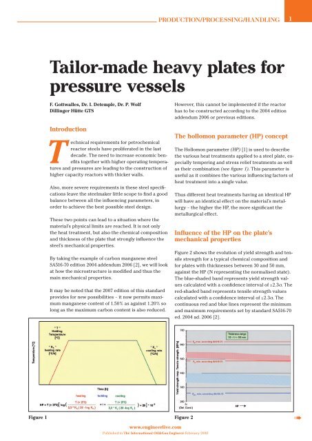
The hollomon parameter (HP) concept<br />
The Hollomon parameter (HP) [1] is used to describe<br />
the various heat treatments applied to a steel plate, especially<br />
tempering and stress relief treatments as well<br />
as their combination (see fi gure 1). This parameter is<br />
useful as it combines the various infl uencing factors of<br />
heat treatment into a single value.<br />
Thus different heat treatments having an identical HP<br />
will have an identical effect on the material’s metallurgy<br />
− the higher the HP, the more signifi cant the<br />
metallurgical effect.<br />
Infl uence of the HP on the plate’s<br />
mechanical properties<br />
Figure 2 shows the evolution of yield strength and tensile<br />
strength <strong>for</strong> a typical chemical composition and<br />
<strong>for</strong> <strong>plates</strong> with thicknesses between 30 and 50 mm,<br />
against the HP (N representing the normalised state).<br />
The blue-shaded band represents yield strength values<br />
calculated with a confi dence interval of ±2.3σ. The<br />
red-shaded band represents tensile strength values<br />
calculated with a confi dence interval of ±2.3σ. The<br />
continuous red and blue lines represent the minimum<br />
and maximum requirements set by standard SA516-70<br />
ed. 2004 ad. 2006 [2].<br />
Figure 1 Figure 2 D<br />
www.engineerlive.com<br />
Published in The International Oil&Gas Engineer February 2008
Figure 3<br />
Figure 4 and 5<br />
We can see that yield strength and tensile strength are<br />
affected by the heat treatment: the harsher the heat<br />
treatment, the more the material’s yield strength and<br />
tensile strength decrease.<br />
Figure 3 shows the evolution of toughness against HP.<br />
The coloured lines represent, <strong>for</strong> various test temperatures,<br />
the lower toughness limits calculated <strong>for</strong> a typical<br />
chemical composition and <strong>for</strong> <strong>plates</strong> with thicknesses<br />
between 30 and 50 mm. 99% of the results are<br />
thus found above this limit. The two horizontal black<br />
lines represent typical minimum values 25 J average<br />
(17 J lowest single value).<br />
We can see that the toughness is strongly affected by<br />
the heat treatment − the harsher the heat treatment,<br />
the more the material’s toughness decreases.<br />
There<strong>for</strong>e, by keeping the chemical composition<br />
constant whatever the HP, the requirements set by<br />
a standard or customer may no longer be complied<br />
with. To counter this effect, the steel’s carbon content<br />
www.engineerlive.com<br />
PRODUCTION/PROCESSING/HANDLING 2<br />
can be adjusted. Figures 4 and 5 are curves of the<br />
expected values of tensile strength and toughness at<br />
–29°C <strong>for</strong> plate thickness of 50 mm and typical chemical<br />
composition by only varying the carbon content<br />
and the HP.<br />
As fi gures 4 and 5 show, the carbon content has to<br />
be increased to ensure the minimum tensile strength<br />
requirement, and it has to be decreased to improve<br />
toughness. For certain carbon contents, and according<br />
to the heat treatment applied, it is no longer possible<br />
to ensure the product’s mechanical requirements<br />
without employing other solutions. These other solutions<br />
will be examined below.<br />
Infl uence of plate thickness on<br />
mechanical properties<br />
Figure 6 shows the evolution of yield strength and<br />
tensile strength, <strong>for</strong> a typical chemical composition<br />
and <strong>for</strong> normalised <strong>plates</strong>, against thickness.<br />
The blue-shaded band represents yield strength<br />
values calculated with a confi dence interval of ±2.3σ.<br />
Figure 6<br />
Published in The International Oil&Gas Engineer February 2008<br />
The red-shaded band represents<br />
tensile strength values calculated<br />
with a confi dence interval<br />
of ±2.3σ. The continuous red and<br />
blue lines represent the minimum<br />
and maximum requirements set<br />
by standard SA516-70 ed. 2004 ad.<br />
2006 [2].<br />
When plate thickness increases,<br />
the material’s yield strength and<br />
tensile strength decrease <strong>for</strong> a<br />
constant chemical composition.<br />
There<strong>for</strong>e, from a certain thickness,<br />
it is no longer possible to<br />
D
Figure 7<br />
ensure the minimum tensile strength requirements set<br />
by the standard by keeping the steel’s same chemical<br />
composition. Normally the carbon content has to be<br />
increased.<br />
Figure 7 shows the evolution of toughness against<br />
plate thickness. The coloured lines represent, <strong>for</strong><br />
various test temperatures, the lower toughness limits<br />
calculated <strong>for</strong> a typical chemical composition. 99% of<br />
the results are thus found above this limit. The two<br />
horizontal black lines represent typical minimum values<br />
25 J average (17 J lowest single value).<br />
For low plate thicknesses, the cooling rate (in air)<br />
is relatively high and can produce a ferritic-perlitic<br />
microstructure containing bainite. This negatively<br />
affects toughness in the untempered state. There<strong>for</strong>e<br />
the chemical composition and/or heat treatment<br />
requires adjustment.<br />
Above a certain thickness where toughness has<br />
reached a maximum, the material’s toughness de-<br />
Figure 8 and 9<br />
www.engineerlive.com<br />
Published in The International Oil&Gas Engineer February 2008<br />
PRODUCTION/PROCESSING/HANDLING 3<br />
creases with increased plate thickness, all other<br />
parameters remaining constant. This phenomenon is<br />
mainly due to increased grain size of the microstructure<br />
since the plate’s cooling rate decreases.<br />
There<strong>for</strong>e, to ensure the minimum requirements of the<br />
standard (or customer), <strong>for</strong> a given test temperature<br />
and thickness, it is necessary to modify the steel’s<br />
chemical composition and/or heat treatment.<br />
Let us look again at the solution of varying the carbon<br />
content to alleviate the negative effect of increasing<br />
the product’s thickness on the material’s mechanical<br />
properties. Figures 8 and 9 show the expected values<br />
of tensile strength and toughness at –29°C <strong>for</strong> a typical<br />
chemical composition of plate in normalised condition<br />
by varying the carbon content and plate thickness. As<br />
in the previous case, it appears necessary both <strong>for</strong> the<br />
carbon content to be increased to ensure the minimum<br />
tensile strength requirement, and to be reduced<br />
to improve toughness.<br />
Finally <strong>for</strong> certain combinations “product thickness –<br />
heat treatment – toughness test temperature – standard<br />
or customer specifi cation”, it can easily be seen<br />
that the single carbon content variation is no longer<br />
suffi cient. Furthermore, carbon negatively affects certain<br />
steel <strong>for</strong>ming properties, especially its suitability<br />
<strong>for</strong> oxycutting or its weldability.<br />
Finally, carbon comes directly into the calculation of<br />
the carbon equivalent which is often limited by the<br />
standards or customer specifi cations.<br />
There<strong>for</strong>e other methods have to be used to adjust the<br />
mechanical properties of the <strong>plates</strong>. However, these<br />
have to comply with the standard or be accepted by<br />
the customer.<br />
D
Alloying<br />
A reduction of carbon in the steel can be offset by<br />
adjusting the steel‘s chemistry using different alloying<br />
elements such as chromium, molybdenum, copper,<br />
nickel and/or niobium. Thus the alloying elements,<br />
by their effect, contribute directly to improving the<br />
steel‘s toughness, or allow to reduce the carbon content<br />
without reducing tensile strength and so indirectly<br />
improving the product‘s toughness.<br />
Figure 10<br />
Figure 10 shows the effect of alloying on the mechanical<br />
properties in the <strong>for</strong>m of zones. These zones<br />
are functions of the thickness and heat treatment<br />
depending on whether a „CMn“ concept or a<br />
„CMn + alloying“ concept is used. These zones represent<br />
(t; HP) combinations <strong>for</strong> which a plate can be<br />
produced according to standard SA516-70 ed. 2004<br />
ad. 2006 with minimum toughnesss in the transverse<br />
direction at quarter thickness of 25 J average<br />
(17 J lowest single value) at –29°C.<br />
However, this concept also has limits and certain<br />
„t; HP“ combinations cannot be reached. Standards<br />
and specifi cations restrict the alloying element content<br />
and these elements infl uence the carbon equivalent<br />
(the most commonly used <strong>for</strong>mula is:<br />
CE = C + Mn/6 + (Cr + Mo + V)/5 + (Ni + Cu)/15). Furthermore,<br />
it should not be <strong>for</strong>gotten that the production<br />
cost of an alloyed plate is signifi cantly higher than<br />
that of a carbon-manganese plate.<br />
There<strong>for</strong>e, it is necessary to explore other avenues, <strong>for</strong><br />
example by directly adjusting the parameters of the<br />
<strong>heavy</strong> plate production process.<br />
PRODUCTION/PROCESSING/HANDLING 4<br />
www.engineerlive.com<br />
Accelerated cooling followed by<br />
tempering<br />
This solution consists in the accelerated cooling of<br />
the <strong>plates</strong> in order to produce a microstructure having<br />
a fi ner grain size and comprised of bainite and<br />
martensite. Nevertheless, to achieve good toughness<br />
on these <strong>plates</strong>, they have to receive a heat treatment<br />
(tempering) after quenching.<br />
However, certain standards or specifi cations do not<br />
permit this special treatment. Yet, according to standard<br />
SA516, <strong>for</strong> thick <strong>plates</strong> it is possible to reproduce<br />
cooling similar to that undergone by a thin plate after<br />
normalisation. This is not a matter of quenching but<br />
just the accelerated and controlled cooling of the thick<br />
<strong>plates</strong>. This accelerated cooling must be followed by<br />
tempering. The plate‘s delivery condition is no longer<br />
„N“ but „N + AC + T“.<br />
The goal is to produce the same microstructure as<br />
thin plate <strong>for</strong> thick plate. Grain size directly infl uences<br />
toughness. By acting on this parameter it is possible<br />
to satisfy the requirements in terms of toughness,<br />
while keeping enough carbon and alloying element<br />
content to reach the required levels of yield strength<br />
and tensile strength.<br />
Figure 11 shows typical plate microstructures obtained<br />
by means of these two types of process.<br />
Figure 11<br />
Published in The International Oil&Gas Engineer February 2008<br />
Figure 12, like fi gure 10, shows the effect of the<br />
„N + AC + T“ treatment on the mechanical properties.<br />
Here the zones also represent (t; HP) combinations <strong>for</strong><br />
which a plate can be produced according to standard<br />
SA516-70 ed. 2004 ad. 2006, with minimum toughness<br />
D
Figure 12<br />
in the transverse direction at quarter thickness of<br />
25 (17) J at –29°C, by the production method used.<br />
By implementing this type of process (when the<br />
standard or the customer specifi cation permits) the<br />
steelmaker can accept more severe requirements in<br />
terms of the (t; HP) combination or in terms of a pure<br />
requirement with constant (t; HP) combination.<br />
Conclusion<br />
By means of various examples we have seen that the<br />
mechanical properties of a <strong>heavy</strong> plate depend on<br />
many parameters. Not only the chemistry employed<br />
in preparing the steel in the steelplant, but also the<br />
thickness of the fi nished product and the type of process<br />
implemented strongly affect the characteristics of<br />
the fi nished product. Thus requirements that are too<br />
severe compared with those defi ned in the standard,<br />
especially when they only take account of part of<br />
the infl uencing parameters or when they are applied<br />
uni<strong>for</strong>mly to an entire range of thicknesses, limit the<br />
steelmaker‘s options to adjust the mechanical properties<br />
of <strong>heavy</strong> plate. For highly demanding specifi cations,<br />
as increasingly required by customers, it is<br />
there<strong>for</strong>e important to hold detail discussions with<br />
the steelmaker be<strong>for</strong>e ordering plate.<br />
PRODUCTION/PROCESSING/HANDLING 5<br />
BIBLIOGRAPHIC REFERENCES<br />
[1] HOLLOMON, John Herbert & JAFFE, L.D.<br />
Time-Temperature relations in Tempering<br />
Steel. Transaction of the AIME, 162, 1645,<br />
223-249<br />
[2] ASME Code Section II Part A, Edition 2004<br />
+ Addenda 2006, SA-516/SA-516M, Specifi -<br />
cation <strong>for</strong> <strong>pressure</strong> vessel <strong>plates</strong>, carbon<br />
steel, <strong>for</strong> moderate- and lower-temperature<br />
service<br />
[3] DETEMPLE Ingo, DEMMERATH Anja,<br />
The Effect of Heat Treatment, Hydrocarbon<br />
Engineering, November 1998, p. 67.<br />
[4] DETEMPLE Ingo, Alloying Concepts,<br />
Hydrocarbon Engineering, December 2003,<br />
p. 64.<br />
ABBREVIATIONS<br />
HP Hollomon Parameter<br />
t Thickness<br />
CE Carbon equivalent<br />
N Normalised<br />
AC Accelerated Cooling<br />
T Tempering<br />
Table 1: Table of abbreviations<br />
www.engineerlive.com<br />
Published in The International Oil&Gas Engineer February 2008
<strong>Dillinger</strong> HIC resistant <strong>pressure</strong> vessel <strong>plates</strong><br />
P.O. Box 1580<br />
66748 Dillingen<br />
Germany<br />
Phone: +49 6831 47-3453<br />
Fax: +49 6831 47-3089<br />
info@dillinger.biz • www.dillinger.de<br />
Statendamweg 81<br />
4905 AD Oosterhout, The Netherlands<br />
P.O. Box 190, 4900 AD Oosterhout,<br />
The Netherlands<br />
Phone: + 31 (0) 162 491500<br />
Fax. : + 31 (0) 162 429806<br />
john.roelands@aws.dillinger.biz<br />
hen.meesterman@aws.dillinger.biz<br />
www.ancoferwaldram.nl<br />
Road 1241, Between Junction 12 & 13<br />
Postfach: 17592, Jebel Ali,<br />
Dubai, United Arab Emirates<br />
Phone: +971 4 8 83 38 94<br />
Fax: +971 4 8 83 38 95<br />
randhir.venugopal@dme.dillinger.biz<br />
pjnarayanan@dme.dillinger.biz<br />
sales@dme.dillinger.biz<br />
www.dillingermiddleeast.com