AXS-100, AXS-100XT - Visonic Technologies
AXS-100, AXS-100XT - Visonic Technologies
AXS-100, AXS-100XT - Visonic Technologies
- No tags were found...

You also want an ePaper? Increase the reach of your titles
YUMPU automatically turns print PDFs into web optimized ePapers that Google loves.
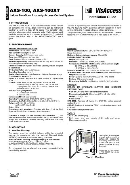
<strong>AXS</strong>-<strong>100</strong>, <strong>AXS</strong>-<strong>100</strong>XTIndoor Two-Door Proximity Access Control SystemInstallation Guide1. INTRODUCTIONThe <strong>AXS</strong>-<strong>100</strong>/<strong>AXS</strong>-<strong>100</strong>XT is an electronic access control systemfor controlling two doors.. Eight controllers can be networkedtogether to control a total of 16 doors. The controller relayactivates a lock or an electromagnetic strike (EMS), when a validproximity key card or tag is presented to the reader. For detailedsystem description, refer to the <strong>AXS</strong>-<strong>100</strong>/<strong>AXS</strong>-<strong>100</strong>XT user’sguide.The use of a proximity (non-contact) key makes the installation ofthe <strong>AXS</strong>-<strong>100</strong>/<strong>AXS</strong>-<strong>100</strong>XT system an attractive possibility in harshenvironments and in places with poor lighting conditions.The proximity keys are totally sealed and wear resistant. The lockreads the key ID, whenever the key is held close to the reader.2. SPECIFICATIONS<strong>AXS</strong>-<strong>100</strong>, <strong>AXS</strong>-<strong>100</strong>XT CONROLLERPower Input: 14 - 16.5 VAC, 50VAMax Current Consumption: 2.5AMemory Capacity: 5,000 access card codesEvent Log: <strong>100</strong>0 records per controllerEvent Printout: RS-232 channel to printer or PCSystem Programming: From controller #1. PC may be connected foruse as supplemental monitoring only.Time Schedules: 64 separate schedules. Each key may be assignedto 2 schedules.Dry Contact Relay: Max 1A continuousDoors Per Controller: Up to 2Readers Per Controller: Up to 2 external + 1 internal (for programming)Controllers Per Network: 8Inputs (x 2 doors): Request-to-exit, door position, 2 programmableinputsOutputs: 2 lock relays, NO/NC dry contact, 30VDC 2A max1 auxiliary relay, NO/NC dry contact, 30V DC 2A maxOutput power for 2 locks: 10.3 - 12VDC, 400mA max2 readers output: 70 mA maxAnti Passback (APB) Modes:1. Local to each controller2. Network APBIndicators (LEDs): 5 (see figure 5)Operating Temperatures: 0°C to 50°C (32°F to 122°F)Dimensions (LxWxD): 315x262x74mm (12-3/8x10-5/16x10-15/16 in)Weight: <strong>AXS</strong>-<strong>100</strong>: 3.8 kg (8.4 lb)<strong>AXS</strong>-<strong>100</strong>XT: 3 kg (6.6 lb)Color: WhiteCompliance with standards: Complies with Part 15 of the FCCRules and RSS-210 of Industry and Science Canada.Operation is subject to the following two conditions: (1) Thisdevice may not cause harmful interference, and (2) this device mustaccept any interference received, including interference that maycause undesired operation.3. MOUNTING3.1 Metal Box MountingThe system must be installed indoors, within the protectedpremise, in accordance with the National Electrical Code(NFPA70) and the local authorities having jurisdiction.For <strong>AXS</strong>-<strong>100</strong>XT use only the supplied plug-in transformer:PRI 120V/60Hz @ 0.59A, SEC 16.5VAC / 50VABE116250CAA0040, Basler Electric, Class 2 NOT WET,Do not connect (the transformer) to a power receptacle that iscontrolled by a switch.READERSOperating Temperatures: -20°C to 50°C (-4°F to 122°F)Color: Dark brownMinimum distance between readers: 60 cm (2 ft)RDR-4 PROXIMITY READERWeight: 121.5 g (4.3 oz)Indicators: Tricolor LED (Green, Red, Amber)Cable (to <strong>AXS</strong>-<strong>100</strong>/<strong>AXS</strong>-<strong>100</strong>XT control unit) maximum length:22 AWG up to 60 m (200 ft)18 AWG up to <strong>100</strong> m (320 ft)Dimensions (LxWxD): 116 x 70 x 16.8 mm (4-1/2 x 2-3/4 x 5/8 in)RDK-4 PROXIMITY READER WITH KEYPAD (optional, not evaluated by UL)Weight: 170 g (6 oz)Power input: 12-16V DC from the <strong>AXS</strong>-<strong>100</strong> / <strong>AXS</strong>-<strong>100</strong>XTButtons: 12 (numeric keypad)Dimensions (LxWxD): 122x82x31mm (4-13/16 x 3-1/2 x 1-1/4 in)CARDS (*)CRD-1SL ISO STANDARD SLOTTED AND NUMBEREDPROXIMITY CARDCard ID: One of a trillion different combinationsDimensions (LxWxD): 85x54x1mm (3 5/16 x 2 1/8 x 1/32 in)Weight: 2.5 g (0.1 oz)Color: WhiteCRD-25SL: Package of twenty-five CRD-1SL slotted proximitycards with printCRD-25: Package of twenty-five CRD-1 non-slotted proximity cards(optional).CRD-25S: Slotted proximity cardTAGS (*)TAG-1: One proximity tag* Both cards and tags contain 40-bit code and usingManchester encoding.Use the box as a templateto mark on the mountingsurface, drill 4 holes on themounting surface andfasten the box to themounting surface by using4 screws.Transformer (<strong>AXS</strong>-<strong>100</strong> only).In <strong>AXS</strong>-<strong>100</strong>XT there is notransformer.Figure 1 - MountingPage 1 of 5DE6280-9
3.2 Metal Box Door Lock AssemblyThe door lock assembly of the system metal box is presented infigure 2 (the lock and the brass nut are supplied in the systemaccessories box).1Align lock with the prepunchedhole andinsert it into the hole.2Place the brass nut on thelock, tighten by hand andfinally tighten withspanner (7/8”). Verify thatyou can lock the door (keyrotation of 90 degrees).Metal box3.3 Backup Battery Installation (Optional)Locate the optional backup battery (12V, 7.0Ah, Lead-acidbattery) in the lower left side of the system enclosure (see fig. 3).3.4 Tamper Switch Installation & WiringIt is necessary to protect the controller against tampering. A ULListed Tamper switch must be installed (see fig. 4) and wired toAUXIN1 and COM of lock #3 of each controller.Backupbattery(optional)Metal box doorFigure 2 - Metal Cabinet Door Lock AssemblyFig. 3 - Backup Battery Fig. 4 - Tamper Switch Installation4. WIRINGBAT-BAT+Battery fuse 3.15AREADER 1PWRGNDTXRXRTEGNDDPOSRELAY 1GNDPWRF2NOCOMNCDOOR 1IN1GNDIN2<strong>AXS</strong>-<strong>100</strong>, <strong>AXS</strong>-<strong>100</strong>XT Wiring DiagramLD3 (green LED)ext. batt. chargedbattery-+holderReplace fuses (x2) with ULListed fuses.WARNING: To reduce risk offire, replace only with the sametype and rate of fuse.Symmetrical connectorsDoor 1 Door 2LD4 (red LED) alarmrelay activatedLD5 (greenLED) outputrelay activatedNOTE:Replace battery with PANASONIC.Type: CR2032, 3V “COIN” battery.Use of another battery may presenta risk of fire or explosion.See user manuals for safety instructions.NOTE:All power outputs are power limitedexcept from the battery outputs.Note:Optional for future useDIP SwitchesEPROMAC fuse 3.15ALD2 (red LED)Power ONF3ACACREADER 2PWRGNDTXRXRTEGNDDPOSRELAY 2GNDPWRNOCOMNCLD1 (green LED)output relayactivatedDOOR 2IN1GNDIN2Plug-in transformer for <strong>AXS</strong>-<strong>100</strong>XTonly: PEI 120V/60Hz @ 0.59A,SEC. 16.5VAC / 50VA.BE116250CAA0040, BaslerElectric. Class 2 NOT WET,UL Listed 49HO.RedBlackGreenWhiteRTE inputD.POS inputWire Jumper(remove for dry contact)Prox. ReaderTwisted pair to A,Bof other <strong>AXS</strong>-<strong>100</strong>Common gnd toother <strong>AXS</strong>-<strong>100</strong>must be connected!Alarm relayto Siren orBellDB-9FTo computerCOM1 or COM21 2 3 4 5 .13 12 11 10 9 8 7 6 5 4 3 2 1DB-25MTo serial printerNOTE:For batteryreplacementseeinstallationinstructions.12V, 7.0AhLead-acid battery(optional)GNDPWRN.O.COMN.C.6 7 8 925 24 23 22 21 20 19 18 17 16 15 14Lock connection configurationsDry contact connection Internal 12V power supplyNormally open (EMS)CommonNormally closed (maglock)GNDPWRN.O.COMN.C.Figure 5 - WiringPage 2 of 5DE6280-9
Each two-door controller connects to two proximity readers and twoelectric locks. It can also be connected to two inputs per door:• Request-to-Exit (RTE) button or PIR near the door in thesecure area will allow a person to open the door from within forleaving.• Door Position micro switch installed between the door and doorframe will provide the controller with door status indications.A. Proximity ReadersEach reader is connected to the controller via a 4-wire cable. Thestandard cable is color coded as follows:• RED Power +• BLACK Power –• GREEN TX• WHITE RXUse an extension cable with the same colors to avoid connectionerrors.Note: Do not install the RDR-4 on a metal surface or a metaldoor frame, since this decreases the read range significantly. Ifyou have to install the reader on a metal surface, use a spacerso that the reader will be at least 1 cm (3/8 in.) away from themetal. You may use RDR-BACK which is an optionallyavailable spacer made specifically for this purposeNote: When installing more than one RDR-4, the distancebetween them should be at least 60 cm (2 ft.), to ensure properoperation.B. InputsBoth inputs (RTE and Door Position) can be connected to eithernormally open or normally closed switches. The default is anormally open RTE and normally closed Door Position (whendoor is shut).C. LocksThe system can operate both electromagnetic strikes - EMS(normally open) and electromagnetic locks - EML (normallyclosed). Each connector block has a COMMON as well as N.O.and N.C. connectors.If the controller is configured for one door, connect it to theEMS/EML, at the left side of the controller.All types of connections are detailed in the next drawing.12VDCNormally OpenNCCOMNOPWRGND-----Power+-----JumperPower12VDCNormally ClosedNCCOMNOPWRGND----------Power+JumperPowerNon-12VDC or Non-12VDC orhigh current high currentdevices - Dry devices - Drycontact N.O. contact N.C.NCNC ------COMNOPWRGND------------COMNOPWRGNDThe lock sections include also 12V power connectors. Theseconnectors provide power to the lock with a current limit of 400mAfor each lock. The controller supplies power from a backup battery ifavailable when the AC power is down. Electromagnetic locks whichconstantly draw a large current, should use the dry contact ONLYwithout connecting the internal power supply. The same holds truefor any other device, which does NOT operate at 12VDC.If you notice problems with a controller operating an EMS thatuses an internal power supply, connect the diode suppliedbetween + and – of the EMS output (see Panel Wiring Diagram).D. Controller NetworkUp to eight system controllers can be connected together in anetwork. The controller provides two 3-connector blocks for daisychaining controllers in a bus configuration.The controllers’ addresses need not be in the physical orderof connection.Connect system units with a single twisted pair cable.Connect terminal A to A and B to B, GND to GND, this way up toeight controllers.E. RS-232 ChannelThe RS-232 channel is used for connecting the <strong>AXS</strong>-<strong>100</strong> / <strong>AXS</strong>-<strong>100</strong>XT to either a computer or a serial printer.The RXD and TXD notation refers to the PC’s RXD and TXDThe use of PC and printer were not evaluated by UL. The PC canbe used as supplemental monitoring and/or for programming anddownloading only.F. Power ConnectionConnect the AC power cable to the power connector on the topright side of the board.G. Backup Battery ConnectionConnect backup battery to black and red wires on the left side.------5. SPECIAL INSTALLER FUNCTIONSThe <strong>AXS</strong>-<strong>100</strong> / <strong>AXS</strong>-<strong>100</strong>XT system has a few special functions,which should not be accessible to the regular user. Thesefunctions allow the installer to initialize the system to a knownstate before starting to set up user data. The functions are:• Reset passwords• Clear key database• Load setup defaults• Setting address & operation mode5.1 Reset PasswordsIf password #1 is not known, it is impossible to change somesystem parameters. The following steps reset the passwords:When the idle screen is displayed, repeatedly press the arrow up(↑) key until a long beep is heard. As a result, Password #1 hasbeen reset to “2975”. Password #2 is cleared.5.2 Clear Keys DatabaseIt is recommended to clear the key database before starting toprogram user keys for the first time.This operation should be performed from controller #1.Follow these steps to clear the keys database:• Enter password #1 and log in into the system.• In EDIT KEYS menu select DELETE KEY screen.• Enter 9999 as the key number and press Enter.• The controller will prompt you with a “Y/N”. Press “1” followedby another Enter to confirm.• The keys database will be erased. The operation will belogged and printed as “DB ERASED”.5.3 Setup DefaultsTo return the system to its default setup, perform the actions thatare shown in figure 6 (text in rectangles represents displayed text).EnterEnterEnterEnter(16 times)1ENTER PASSWORDXXXXDATE TYPEDATE/TIMEAPB RESET HOUR99:00PC PASSWORD65535LOAD SETUPDEFAULTS (Y/N)YEnterEnterSETUPEDIT KEYSEDIT REGISTERLOCAL SETUPSETUP FLAGS 1- - - - - - 7 8Figure 6 - Returning to Setup DefaultsLOAD SETUPDEFAULTS (Y/N)N(long beep is heardto indicate success)Page 3 of 5DE6280-8
5.4 Setting Address & Operation ModeSetting the controller address and operation mode, in <strong>AXS</strong>-<strong>100</strong> /<strong>AXS</strong>-<strong>100</strong>XT version 2.06 and above, is performed by using thecontroller keypad (not by using DIP switches) - see figure 7.EnterENTER PASSWORDXXXXEnterEnterThe display will be:SETUPEDIT KEYSEDIT REGISTERSLOCAL SETUPEnter controller No. (e.g. 1)CONTROLLEREnter14 timesSelect operation mode (e.g. 7)MODEEnter Enter Esc Esc7Note: Mode list is attachedto the <strong>AXS</strong>-<strong>100</strong> door.Figure 7 - Controller Address and Operation Mode Setting6. MAINTENANCE6.1 Replacement Parts List1. Lithium battery 3V, cat. No. 0-9913-0.2. CRD-1, cat. No. 0-9923-2, or 0-9923-8.3. Proximity reader RDR-4, cat. No. 3-6304-06.2 Periodic CheckOnce a month, the system must be checked by presenting atag/card to the reader and verifying that the proper door is opened.6.3 Lithium Battery Handling/DisposalCaution: Battery may explode if mistreated, do not recharge,disassemble or dispose in fire.Replace battery with PANASONIC Coin battery type CR2032, 3Vonly. Use of another battery may present a risk of fire or explosion.Dispose any used Lithium battery only in an approved disposalcontainer.This device complies with the essential requirements and provisions of Directive 1999/5/EC of the European Parliament and of the Council of 9March 1999 on radio and telecommunications terminal equipment.WARNING! Changes or modifications to this unit not expressly approved by the party responsible for compliance could void the user'sauthority to operate the equipment.WARRANTY<strong>Visonic</strong> <strong>Technologies</strong> Ltd. and/or its subsidiaries and its affiliates ("the Manufacturer")warrants its products hereinafter referred to as "the Product" or "Products" to be inconformance with its own plans and specifications and to be free of defects in materialsand workmanship under normal use and service for a period of twelve months from thedate of shipment by the Manufacturer. The Manufacturer's obligations shall be limitedwithin the warranty period, at its option, to repair or replace the product or any partthereof. The Manufacturer shall not be responsible for dismantling and/or reinstallationcharges. To exercise the warranty the product must be returned to the Manufacturerfreight prepaid and insured.This warranty does not apply in the following cases: improper installation, misuse,failure to follow installation and operating instructions, alteration, abuse, accident ortampering, and repair by anyone other than the Manufacturer.This warranty is exclusive and expressly in lieu of all other warranties, obligations orliabilities, whether written, oral, express or implied, including any warranty ofmerchantability or fitness for a particular purpose, or otherwise. In no case shall theManufacturer be liable to anyone for any consequential or incidental damages for breachof this warranty or any other warranties whatsoever, as aforesaid.This warranty shall not be modified, varied or extended, and the Manufacturer does notauthorize any person to act on its behalf in the modification, variation or extension of thiswarranty. This warranty shall apply to the Product only. All products, accessories orattachments of others used in conjunction with the Product, including batteries, shall becovered solely by their own warranty, if any. The Manufacturer shall not be liable for anydamage or loss whatsoever, whether directly, indirectly, incidentally, consequentially orotherwise, caused by the malfunction of the Product due to products, accessories, orattachments of others, including batteries, used in conjunction with the Products.The Manufacturer does not represent that its Product may not be compromised and/orcircumvented, or that the Product will prevent any death, personal and/or bodily injuryand/or damage to property resulting from burglary, robbery, fire or otherwise, or that theProduct will in all cases provide adequate warning or protection. User understands that aproperly installed and maintained alarm may only reduce the risk of events such asburglary, robbery, and fire without warning, but it is not insurance or a guarantee thatsuch will not occur or that there will be no death, personal damage and/or damage toproperty as a result.The Manufacturer shall have no liability for any death, personal and/or bodily injuryand/or damage to property or other loss whether direct, indirect, incidental,consequential or otherwise, based on a claim that the Product failed to function.However, if the Manufacturer is held liable, whether directly or indirectly, for any loss ordamage arising under this limited warranty or otherwise, regardless of cause or origin, theManufacturer's maximum liability shall not in any case exceed the purchase price of theProduct, which shall be fixed as liquidated damages and not as a penalty, and shall bethe complete and exclusive remedy against the Manufacturer.Warning: The user should follow the installation and operation instructions and amongother things test the Product and the whole system at least once a week. For variousreasons, including, but not limited to, changes in environmental conditions, electric orelectronic disruptions and tampering, the Product may not perform as expected. The useris advised to take all necessary precautions for his /her safety and the protection ofhis/her property.6/91VT World Headquarters * Tel Aviv, Israel * Tel: + 972 3 768-1400 * support@visonictech.comVT Americas * Bloomfield, CT (USA) * Tel: 1-800-223-0020 * vta_support@visonictech.comVT United Kingdom * Beckenham Kent BR3 90BF, U.K. * Tel: + 44-870-730-0840 * vtuk_support@ visonictech.com<strong>Visonic</strong> GmbH * D-40215 Düsseldorf, Germany * Tel: + 49-0-211-600-696-0 * support@ visonictech.deAdditional information may be found at: www.visonictech.comPage 4 of 5DE6280-9 Oct. 09W.E.E.E. Product Recycling DeclarationFor information regarding the recycling of this product you must contact the company from which you orignially purchased it.If you are discarding this product and not returning it for repair then you must ensure that it is returned as identified by yoursupplier. This product is not to be thrown away with everyday waste.Directive 2002/96/EC Waste Electrical and Electronic Equipment.
DE6280 5