Full Resolution Lightfield Rendering - Todor Georgiev
Full Resolution Lightfield Rendering - Todor Georgiev
Full Resolution Lightfield Rendering - Todor Georgiev
- No tags were found...

Create successful ePaper yourself
Turn your PDF publications into a flip-book with our unique Google optimized e-Paper software.
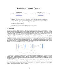
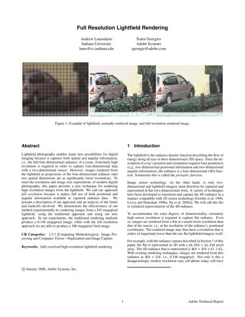
<strong>Full</strong> <strong>Resolution</strong> <strong>Lightfield</strong> <strong>Rendering</strong>Andrew LumsdaineIndiana Universitylums@cs.indiana.edu<strong>Todor</strong> <strong>Georgiev</strong>Adobe Systemstgeorgie@adobe.comFigure 1: Example of lightfield, normally rendered image, and full-resolution rendered image.Abstract<strong>Lightfield</strong> photography enables many new possibilities for digitalimaging because it captures both spatial and angular information,i.e., the full four-dimensional radiance, of a scene. Extremely highresolution is required in order to capture four-dimensional datawith a two-dimensional sensor. However, images rendered fromthe lightfield as projections of the four-dimensional radiance ontotwo spatial dimensions are at significantly lower resolutions. Tomeet the resolution and image size expectations of modern digitalphotography, this paper presents a new technique for renderinghigh resolution images from the lightfield. We call our approachfull resolution because it makes full use of both positional andangular information available in captured radiance data. Wepresent a description of our approach and an analysis of the limitsand tradeoffs involved. We demonstrate the effectiveness of ourmethod experimentally by rendering images from a 542 megapixellightfield, using the traditional approach and using our newapproach. In our experiments, the traditional rendering methodsproduce a 0.146 megapixel image, while with the full resolutionapproach we are able to produce a 106 megapixel final image.CR Categories: I.3.3 [Computing Methodologies]: Image Processingand Computer Vision—Digitization and Image CaptureKeywords: fully-resolved high-resolution lightfield rendering1 IntroductionThe lightfield is the radiance density function describing the flow ofenergy along all rays in three-dimensional (3D) space. Since the descriptionof a ray’s position and orientation requires four parameters(e.g., two-dimensional positional information and two-dimensionalangular information), the radiance is a four-dimensional (4D) function.Sometimes this is called the plenoptic function.Image sensor technology, on the other hand, is only twodimensionaland lightfield imagery must therefore be captured andrepresented in flat (two dimensional) form. A variety of techniqueshave been developed to transform and capture the 4D radiance in amanner compatible with 2D sensor technology [Gortler et al. 1996;Levoy and Hanrahan 1996a; Ng et al. 2005a]. We will call this flator lightfield representation of the 4D radiance.To accommodate the extra degrees of dimensionality, extremelyhigh sensor resolution is required to capture flat radiance. Evenso, images are rendered from a flat at a much lower resolution thanthat of the sensor, i.e., at the resolution of the radiance’s positionalcoordinates. The rendered image may thus have a resolution that isorders of magnitude lower than the raw flat lightfield imagery itself.For example, with the radiance camera described in Section 7 of thispaper, the flat is represented in 2D with a ¾ ¾ ¢ ¾½ ½ pixelarray. The 4D radiance that is represented is ¼ ¢ ¿ ¢ ½ ¢ ½.With existing rendering techniques, images are rendered from thisradiance at ¼ ¢ ¿, i.e., 0.146 megapixel. Not only is this adisappointingly modest resolution (any cell phone today will havec January 2008, Adobe Systems, Inc.1 Adobe Technical Report
etter resolution), any particular rendered view basically only usesone out of every 3,720 pixels from the flat imagery.The enormous disparity between the resolution of the flat and therendered images is extraordinarily wasteful for photographers whoare ultimately interested in taking photographs rather than capturingflat representations of the radiance. As a baseline, we would like tobe able to render images at a resolution equivalent to that of moderncameras, e.g., on the order of 10 megapixels. Ideally, we wouldlike to render images at a resolution approaching that of the highresolution sensor itself, e.g., on the order of 100 megapixels. Withsuch a capability, radiance photography would be practical almostimmediately.In this paper we present a new radiance camera design and techniquefor rendering high-resolution images from flat lightfield imageryobtained with that camera. Our approach exploits the factthat at every plane of depth the radiance contains a considerableamount of positional information about the scene, encoded in theangular information at that plane. Accordingly, we call our approachfull resolution because it makes full use of both angularand positional information that is available in the four-dimensionalradiance. In contrast to super-resolution techniques, which createhigh-resolution images from sub-pixel shifted low-resolution images,our approach renders high-resolution images directly from theradiance data. Moreover, our approach is still amenable to standardradiance processing techniques such as Fourier slice refocusing.The plan of this paper is as follows. After briefly reviewing imageand camera models in the context of radiance capture, we developan algorithm for full resolution rendering of images directly fromflats. We analyze the tradeoffs and limitations of our approach. Experimentalresults show that our method can produce full-resolutionimages that approach the resolution that would have been captureddirectly with a high-resolution camera.ContributionsThis paper makes the following contributions.¯ We present an analysis of plenoptic camera structure that providesnew insight on the interactions between the lens systems.¯ Based on this analysis, we develop a new approach to lightfieldrendering that fully exploits the available information encodedin the four-dimensional radiance to create final imagesat a dramatically higher resolution than traditional techniques.We demonstrate a ¾¢ increase in resolution of images renderedfrom flat lightfield imagery.2 Related WorkSpatial/Angular Tradeoffs A detailed analysis of light transportin different media, including cameras, is presented in [Durand et al.2005]. Discussions of the spatial and angular representational issuesare also discussed in (matrix) optics texts such as [Gerrardand Burch 1994]. A discussion of the issues involved in balancingthe tradeoffs between spatial and angular resolution was discussedin [<strong>Georgiev</strong> et al. 2006]. In that paper, it was proposedthat lower angular resolution could be overcome via interpolation(morphing) techniques so that more sensor real-estate could be devotedto positional information. Nonetheless, the rendering techniqueproposed still assumed rendering at the spatial resolution ofthe captured lightfield imagery.Dappled/Heterodyning In the paper [Veeraraghavan et al. 2007],the authors describe a system for “dappled photography” for capturingradiance in the frequency domain. In this approach, the radiancecamera does not use microlenses, but rather a modulatingmask. The original high-resolution image is recovered by a simpleinversion of the modulation due to the mask. However, the authorsdo not produce a high-resolution image refocused at differentdepths.Super <strong>Resolution</strong> Re-creation of high-resolution images fromsets of low resolution images (“super-resolution”) has been an activeand fruitful area of research in the image processing community[Borman and Stevenson 1998; Elad and Feuer 1997; Farsiuet al. 2004; Hunt 1995; Park et al. 2003] With traditional superresolutiontechniques, high-resolution images are created from multiplelow-resolution images that are shifted by sub-pixel amountswith respect to each other. In the lightfield case we do not havecollections of low-resolution in this way. Our approach thereforerenders high-resolution images directly from the lightfield data.3 CamerasTraditional photography renders a three-dimensional scene onto atwo-dimensional sensor. With modern sensor technologies, highresolutions (10 megapixels or more) are available even in consumerproducts. The image captured by a traditional camera essentiallyintegrates the radiance function over its angular portion, resulting ina two-dimensional intensity as a function of position. The angularinformation of the original radiance is lost.Techniques for capturing angular information in addition to positionalinformation began with fundamental approach of integralphotography which was proposed in 1908 by Lippmann [Lippmann1908]. The large body of work covering more than 100 years of historyin this area begins with the first patent filed by Ives [Ives 1903]in 1903, and continues to plenoptic [Adelson and Wang 1992] andhand-held plenoptic [Ng et al. 2005b] cameras today.3.1 Traditional CameraIn a traditional camera, the main lens maps the 3D world of thescene outside of the camera into a 3D world inside of the camera(see Figure 2). This mapping is governed by the well-known lensIn much of the original work on lightfield rendering (cf. [Gortleret al. 1996; Levoy and Hanrahan 1996b]) and in work thereafter(e.g., [Isaksen et al. 2000; Ng et al. 2005b]), the assumption hasbeen that images are rendered at the spatial resolution of the radiance.Figure 2: Imaging in a traditional camera. Color is used to representthe order of depths in the outside world, and the correspondingdepths inside the camera. One particular film plane is representedas a green line.2 Adobe Technical Report
equation½ · ½ ½ where and are respectively the distances from the lens to theobject plane and to the image plane. This formula is normallyused to describe the effect of a single image mapping between twofixed planes. In reality, however, it describes an infinite number ofmappings—it constrains the relationship between, but does not fix,the values of the distances and . That is, every plane in theoutside scene (which we describe as being at some distance fromthe lens) is mapped by the lens to a corresponding plane inside ofthe camera at distance . When a sensor (film or a CCD array) isplaced at a distance between and ½ inside the camera, it capturesan in-focus image of the corresponding plane at that wasmapped from the scene in front of the lens.3.2 Plenoptic CameraA radiance camera captures angular as well as positional informationabout the radiance in a scene. One means of accomplishingthis is with the use of an array of microlenses in the camera body,the so-called plenoptic camera (see Figure 3).The traditional optical analysis of such a plenoptic camera considersit as a cascade of a main lens system followed by a microlenssystem. The basic operation of the cascade system is as follows.Rays focused by the main lens are separated by the microlenses andcaptured on the sensor. At their point of intersection, rays have thesame position but different slopes. This difference in slopes causesthe separation of the rays when they pass through a microlens-spacesystem. In more detail, each microlens functions to swap the positionaland angular coordinates of the radiance; then this new positionalinformation is captured by the sensor. Because of the swap,it represents the angular information at the microlens. The appropriateformulas can be found for example in [<strong>Georgiev</strong> and Intwala2006]. As a result, each microlens image represents the angular informationfor the radiance at the position of the optical axis of themicrolens.image.) If the angular information is finely sampled, then an enormousnumber of pixels from the flat lightfield imagery are beingused to create just one pixel in the rendered image. If the microlensproduces, say, a ½ ¢ ½ array of angular information, we are trading3,721 pixels in the flat for just one pixel in the rendered image.Of course, the availability of this angular information allows us toapply a number of interesting algorithms to the radiance imagery.Nonetheless, the expectation of photographers today is to work withmulti-megapixel images. It may be the case that some day in the future,plenoptic cameras with multi-millions of microlenses will beavailable (with the corresponding multi-gigapixel sensors). Untilthen, we must use other techniques to generate high-resolution imagery.3.3 Plenoptic Camera 2.0In the plenoptic camera the microlenses are placed and adjustedaccurately to be exactly at one focal length from the sensor. Inmore detail, quoting from [Ng et al. 2005a] section 3.1:“The image under a microlens dictates the directional resolution ofthe system for that location on the film. To maximize the directionalresolution, we want the sharpest microlens images possible.This means that we should focus the microlenses on the principalplane of the main lens. Since the microlenses are vanishingly smallcompared to the main lens, the main lens is effectively fixed at themicrolenses’ optical infinity. Thus, to focus the microlenses we cementthe photosensor plane at the microlenses’ focal depth.”This is the current state of the art.Our new approach, however, offers some significant advantages. Inorder to maximize resolution, i.e., to achieve sharpest microlensimages, the microlenses should be focused on the image created bythe main lens, not on the main lens. This makes our new cameradifferent from Ng’s plenoptic camera. In the plenoptic camera, microlensesare “cemented” at distance from the sensor and thusfocused at infinity. As we will see in Section 7, our microlenses areplaced at distance ¿ in the current experiment. The additionalspacing has been created by adding microsheet glass between thefilm and the microlenses in order to displace them by additional½¿ ¼¾ÑÑ from the sensor. In this sense, we are proposing“plenoptic camera ¾¼” or perhaps could be called “the 0.2 mmspacing camera” (see Figure 4).Figure 3: Basic plenoptic camera model. The microlens-space systemswaps positional and angular coordinates of the radiance at themicrolens. For clarity we have represented only the rays throughone of the microlenses.Images are rendered from the radiance by integrating over the angularcoordinates, producing an intensity that is only a function ofposition. Note, however, the resolution of the intensity functionwith this approach. Each microlens determines only one pixel inthe rendered image. (When you integrate the angular informationunder one microlens, you only determine one pixel in the renderedFigure 4: Our proposed radiance camera (plenoptic camera 2.0)with microlens array focused at the image plane.Analysis in the coming sections will show that focusing on the imagerather than on the main lens allows our system to fully exploitpositional information available in the captured flat. Based on good3 Adobe Technical Report
focusing and high resolution of the microlens images, we are ableto achieve very high resolution of the rendered image (e.g., a ¾¢increase in each spatial dimension).4 Plenoptic Camera Modes of BehaviorThe full resolution rendering algorithm is derived by analyzing theoptical system of the plenoptic camera. We begin with some observationsof captured lightfield imagery and use that to motivate thesubsequent analysis.4.1 General ObservationsFigure 5 shows an example crop from a raw image that is acquiredwith a plenoptic camera. Each microlens in the microlens array createsa microimage; the resulting lightfield imagery is thus an arrayof microimages. On a large scale the overall image can be perceivedwhereas the correspondence between the individual microlens imagesand the large scale scene is less obvious. Interestingly, as wewill see, it is this relationship—between what is captured by the microlensesand what is in the overall scene—that we exploit to createhigh-resolution images.On a small scale in Figure 5 we can readily notice a number ofclearly distinguishable features inside the circles, such as edges.Edges are often repeated from one circle to the next. The same edge(or feature) may be seen in multiple circles, in a slightly differentposition that shifts from circle to circle. If we manually refocusthe main camera lens we can make a given edge move and, in fact,change its multiplicity across a different number of consecutive circles.part of the scene is out of focus. When an object from the largescale scene is in focus, the same feature appears only once in thearray of microimages.In interpreting the microimages, it is important to note that, as withthe basic camera described above, the operation of the basic plenopticcamera is far richer than a simple mapping of the radiance functionat some plane in front of the main lens onto the sensor. Thatis, there are an infinite number of mappings from the scene in frontof the lens onto the image sensor. For one particular distance thiscorresponds to a mapping of the radiance function. What the correspondenceis for parts of the scene at other distances—as well ashow they manifest themselves at the sensor—is less obvious. Thiswill be the topic of the remaining part of this section.Next we will consider two limiting cases which can be recognizedin the behavior of the the plenoptic camera: Telescopic and Binocular.Neither of those cases is exact for a true plenoptic camera, buttheir fingerprints can be seen in every plenoptic image. As we showlater in this paper, they are both achievable exactly, and very useful.4.2 Plenoptic Camera: Telescopic CaseWe may consider a plenoptic camera as an array of (Keplerian) telescopeswith a common objective lens. (For the moment we willignore the issue of microlenses not being exactly focused for thatpurpose.) Each individual telescope in the array has a micro camera(an eyepiece lens and the eye) inside the big camera: Just like anyother camera, this micro camera is focused onto one single planeand maps the image from it onto the retina, inverted and reducedin size. A camera can be focused only for planes at distances rangingfrom to infinity according to ½ ·½ ½. Here, , ,and have the same meaning as for the big camera, except on asmaller scale. We see that since and must be positive, we cannot possibly focus closer than . In the true plenoptic camera theimage plane is fixed at the microlenses. In [<strong>Georgiev</strong> and Intwala2006] we have proposed that it would be more natural to considerthe image plane fixed at fistance in front of the microlenses. Inboth cases micro images are out of focus.Figure 6: Details of “telescopic” imaging of the focal plane in apleoptic camera. Note that the image is inverted.Figure 5: Repeated edges inside multiple circles.Repetition of features across microlenses is an indication that thatAs we follow the movement of an edge from circle to circle, wecan readily observe characteristic behavior of telescopic imaging inthe flat lightfield. See Figure 7, which is a crop from the roof areain Figure 5. As we move in any given direction, the edge movesrelative to the circle centers in the same direction. Once detectedin a given area, this behavior is consistent (valid in all directionsin that area). Careful observation shows that images in the little4 Adobe Technical Report
circles are indeed inverted patches from the high resolution image,as if observed through a telescope.is due to the depth in the image at that location. Careful observationshows that images in the little circles are in fact patches fromthe corresponding area in the high resolution image, only reducedin size. The more times the feature is repeated in the circles, thesmaller it appears and thus a bigger area is imaged inside each individualcircle.Figure 7: “Telescopic” behavior shown in close up of the roof edgein Figure 5. We observe how the edge is repeated 2 times as wemove away from the roof. The further from the roof a circle is, thefurther the edge appears inside that circle.4.3 Plenoptic Camera: Binocular CaseWe may also consider a plenoptic camera as an “incompletely focused”camera, i.e., a camera focused behind the film plane (as in aGalilean telescope/binoculars). If we place an appropriate positivelens in front of the film, the image would be focused on the film.For a Galilean telescope this is the lens of the eye that focuses theimage onto the retina. For a plenoptic camera this role is playedby the microlenses with focal length . They need to be placed atdistance smaller than from the film. Note also that while the telescopicoperation inverts the inside image, the binocular operationdoes not invert it.Figure 9: “Binocular” behavior shown in close up of Figure 5. Notehow edges are repeated about 2 or 3 times as we move away fromthe branch. The further from the branch we are, the closer to thebranch the edge appears inside the circle.4.4 ImagesTo summarize, our approximately focused plenoptic camera can beconsidered as an array of micro cameras looking at an image planein front of them or behind them. Each micro camera images onlya small part of that plane. The shift between those little images isobvious from the geometry (see Section 5). If at least one microcamera could image all of this plane, it would capture the high resolutionimage that we want. However, the little images are limitedin size by the main lens aperture.The magnification of these microcamera images, and the shift betweenthem, is defined by the distance to the image plane. It can beat positive or negative distance from the microlenses, correspondingto the telescopic (positive) and binocular (negative) cases. Byslightly adjusting the plane of the microlenses (so they are exactlyin focus), we can make use of the telescopic or binocular focusingto patch together a full-resolution image from the flat. We describethis process in the following sections.5 AnalysisFigure 8: Details of “binocular” imaging in lightfield camera. Notethat the image is not inverted.As with telescopic imaging, we can readily observe characteristicbehavior of binocular imaging in the plenoptic camera. See Figure9, which is a crop from the top left corner in Figure 5. If wemove in any given direction, the edge moves relative to the circlecenters in the opposite direction. Once detected in a given area,this behavior is consistent (valid in all directions in that area). ItOften, microlenses are not focused exactly on the plane we want toimage, causing the individual microlens images to be blurry. Thislimits the amount of resolution that can be achieved. One way toimprove such results would be deconvolution. Another way wouldbe to stop down the microlens apertures.In Figure 10 we consider the case of “plenoptic” camera using pinholearray instead of microlens array. In ray optics, pinhole imagesproduce no defocus blur, and in this way are perfect, in theory. Inthe real world pinholes are replaced with finite but small aperturesand microlenses.5 Adobe Technical Report
Figure 10: An array of pinholes (or microlenses) maps the arealimage in front of them to the sensor. The distance a=nfto theareal image defines the magnification factor M=n-1.From the lens equation½ · ½ ½ we see that if the distance to the object is Ò, the distance tothe image would beÒÒÒ ½ We define the geometric magnification factor as Å , whichby substition gives usÅ Ò ½Figure 10 shows the ray geometry in the telescopic cases for Ò and Ò ¾. Note that the distance from the microlenses to thesensor is always greater than (this is not represented to scale inthe figure). Looking at the geometry in Figure 10, the images areÅ times smaller, inverted, and repeated Å times.6 AlgorithmSection 4 describes two distinct behaviors (telescopic and binocular),and our algorithm executes a different action based on whichbehavior was observed in the microimages.Telescopic: If we observe edges (or features) moving relative tothe circle centers in the same direction as the direction inwhich we move, invert all circle images in that area relative totheir individual centers.Binocular: If we observe edges moving relative to the circle centersin a direction opposite to the direction we move, do nothing.The small circles are, effectively, puzzle pieces of the big image,and we reproduce the big image by bringing those circles sufficientlyclose together.The big image could also have been reproduced had we enlarged thepieces so that features from any given piece match those of adjacentpieces. Assembling the resized pieces reproduces exactly the highresolution image.In either of these approaches the individual pieces overlap. Ouralgorithm avoids this overlapping by dropping all pixels outside thesquare of side Ñ.Prior work did not address the issue of reassembling pixels in thisway because the plenoptic camera algorithm [Ng 2005] producesone pixel per microlens for the output image. Our remarkable gainFigure 11: A lens circle of diameter and a patch of size Ñ.in resolution is equal to the number of pixels Ñ in the originalpatches.That is, we produce Ñ ¢ Ñ pixels instead of one. See Figure 11.Above we have shown that the magnification Å Ò ½. Nowwesee that also Å Ñ. It therefore follows thatÒ ½·Ñ The distance (measured in number of focal lengths) to the imageplane in front of the microlens is related to and Ñ.It is important to note that lenses produce acceptable images evenwhen they are not exactly in focus. Additionally, out of focus imagescan be deconvolved, or simply sharpened. That’s why theabove analysis is actually applicable for a wide range of locationsof the image plane. Even if not optimal, such a result is often auseful tradeoff. That’s the working mode of the plenoptic camera,which produces high quality results [Ng 2005].The optics of the microlens as a camera is the main factor determiningthe quality of each micro image. Blurry images from opticaldevices can be deconvolved and the sharp image recovered to someextent. In order to do this we need to know the effective kernel ofthe optical system. While there are clear limitations in this relatedto bit depth and noise, in many cases we may hope to increase resolutionall the way up to m times the resolution of the plenopticcamera. In this paper we demonstrate ¾¢ increase of resolutionin one plane, and 10 times increase of resolution in another planewithout any deconvolution.7 Experimental Results7.1 Experimental SetupCamera For this experiment we used a large format film camerawith a 135mm objective lens. The central part of our camera is amicrolens array. See Figure 12. We chose a film camera in orderto avoid the resolution constraint of digital sensors. In conjunctionwith a high resolution scanner large format film cameras are capableof 1 gigapixel resolution.The microlens array consists of 146 thousand microlenses of diameter0.25 mm and focal length 0.7 mm. The microlens arrayis custom made by Leister Technologies, LLC. We crafted a specialmechanism inside a 4 X 5 inch film holder. The mechanismholds the microlens array so that the flat side of the glass base ispressed against the film. We conducted experiments both with andwithout inserting microsheet glass between the array and the film.6 Adobe Technical Report
Figure 12: A zoom into our microlens array showing individuallenses and (black) chromium mask between them.The experiments where the microsheet glass was inserted providedspacing in a rigorously controlled manner.In both cases our microlenses’ focal length is ¼¼ mm; Thespacings in the two experimental conditions differ as follows:¯ ¼½ mm so that Ò ½and Å ¼which is madepossible directly by the thickness of the glass; and¯ ¼ mm based on microsheet glass between microlensarray and film. As a result Ò ¿ (almost 4) and Å ¿,approximately.Computation The software used for realizing our processing algorithmwas written using the Python programming language andexecuted with Python version 2.5.1. The image I/O, FFT, andinterpolation routines were resepectively provided by the PythonImaging Library (version 1.1.6) [pil ], Numerical Python (version1.0.3.1) [Oliphant 2006], and SciPy (version 0.6.0) [Jones et al.2001–]. All packages were compiled in 64-bit mode using the Intelicc compiler (version 9.1).The computational results were obtained using a computer systemwith dual quad-core Intel L5320 Xeon processors running at 1.86Ghz. The machine contained 16GB of main memory. The operatingsystem used was Red Hat Enterprise Linux with the 2.6.18 kernel.The time required to render an image with our algorithm is proportionalto the number of microlenses times the number of pixelssampled under each microlens. In other words, the time required torender an image with our algorithm is directly proportional to thesize of the output image. Even though no particular attempts weremade to optimize the performance of our implementation, we wereable to render 100 megapixel images in about two minutes, muchof which time was actually spent in disk I/O.7.2 High-<strong>Resolution</strong> <strong>Rendering</strong> ResultsFigures 13 through 16 show experimental results from applying thefull resolution rendering algorithm. In particular, we show the operationof rendering in botrh the telescopic case and the binocularcase.The original image was digitized with the camera, film, and scanningprocess described above. After digitization, the image measures24,862 ¢ 21,818 pixels. A small crop from the lightfieldimage was shown in Figure 5. A larger crop from the flat lightfieldis shown in Figure 13.An image rendered from the lightfield in the traditional way isshown in Figure 14. Also shown in the figure (upper right hand)is a crop of the curb area rendered at full resolution. On the upperleft is shown zoom in of the same area cropped directly from thetraditionally rendered image. Note that each pixel appears as a 27¢ 27 square, and the enormous increase in resolution.In Figure 15 we show a full resolution rendering of the experimentallightfield, rendered assuming the telescopic case. For this rendering,the scaling-down factor Å was taken to be approximately 2.4,so that the full resolution rendered image measured 11016 ¢ 9666,i.e., over 100 megapixels. In this paper we only show a 2,250 ¢1,950 region. The image is well-focused at full resolution in theregion of the house but not well-focused on the tree branches.In Figure 16 we show a full resolution rendering of the experimentallightfield, rendered assuming the binocular case. Note that incontrast to the image in Figure 15, this image is well-focused at fullresolution in the region of the tree branches but not well-focused onthe house.8 ConclusionIn this paper we have presented an analysis of lightfield camerastructure that provides new insight on the interactions between themain lens system and the microlens array system. By focusing themicrolenses on the image produced by the main lens, our camera isable to fully capture the positional information of the lightfield. Wehave also developed an algorithm to render full resolution imagesfrom the lightfield. This algorithm produces images at a dramaticallyhigher resolution than traditional lightfield rendering techniques.With the capability to produce full resolution rendering, we cannow render images at a resolution expected in modern photography(e.g., 10 megapixel and beyond) without waiting for significant advancesin sensor or camera technologies. <strong>Lightfield</strong> photography issuddenly much more practical.ReferencesADELSON, T.,AND WANG, J. 1992. Single lens stereo with aplenoptic camera. IEEE Transactions on Pattern Analysis andMachine Intelligence, 99–106.BORMAN, S.,AND STEVENSON, R. 1998. Super-resolution fromimage sequences-a review. Proceedings of the 1998 MidwestSymposium on Circuits and . . . (Jan).DURAND, F.,HOLZSCHUCH, N.,SOLER, C.,CHAN, E., ANDSILLION, F. 2005. A frequency analysis of light transport. ACMTrans. Graph., 1115–1126.ELAD, M.,AND FEUER, A. 1997. Restoration of a single superresolutionimage from several blurred, noisy, and undersampledmeasured.... Image Processing.FARSIU, S., ROBINSON, D., ELAD, M., AND MILANFAR, P.2004. Advances and challenges in super-resolution. InternationalJournal of Imaging Systems and Technology.GEORGIEV, T.,AND INTWALA, C. 2006. Light-field camera designfor integral view photography. Adobe Tech Report.GEORGIEV, T.,ZHENG, K.,CURLESS, B.,SALESIN, D., ANDET AL. 2006. Spatio-angular resolution tradeoff in integral photography.Proc. Eurographics Symposium on <strong>Rendering</strong>.7 Adobe Technical Report
Figure 13: Crop of our lightfield. The full image is 24,862 ¢ 21,818 pixels, of which 3,784 ¢ 3,291 are shown here. This region of the imageis marked by the red box in Figure 14.8 Adobe Technical Report
Figure 14: The entire lightfield rendered with the traditional method, resulting in a ¼ ¢ ¿ pixel image. Above are shown two smallcrops that represent a ¾¢ magnification of the same curb area. The left one is generated with traditional lightfield rendering; the right one isgenerated with full resolution rendering. A comparison demonstrates the improvement that can be achieved with the proposed method. Thered box marks the region shown in Figure 13. The green box marks the region that is shown in Figures 15 and 16.9 Adobe Technical Report
Figure 15: A crop from a full resolution rendering of the experimental lightfield. Here, the entire image is rendered assuming the telescopiccase. We take the scaling down factor Å to be approximately 2.4, resulting in a 11016 ¢ 9666 full resolution image (100 megapixel). A2,250 ¢ 1,950 region of the image is shown here. Note that in this case the image is well-focused at full resolution in the region of the housebut not well-focused on the tree branches. This region of the image is marked by the green box in Figure 14.10 Adobe Technical Report
Figure 16: A crop from a full resolution rendering of the experimental lightfield. The entire image is rendered assuming the binocular case.Thesame2,250¢ 1,950 region as in Figure 15 is shown here. Note that in this case the image is well-focused at full resolution in the regionof the tree branches but not well-focused on the house. In other words, only blocks representing the branches match each-other correctly.This region of the image is marked by the green box in Figure 14.11 Adobe Technical Report
GERRARD, A.,AND BURCH, J. M. 1994. Introduction to matrixmethods in optics.GORTLER,S.J.,GRZESZCZUK,R.,SZELISKI,R.,AND COHEN,M. F. 1996. The lumigraph. ACM Trans. Graph., 43–54.HUNT, B. 1995. Super-resolution of images: algorithms, principles,performance. International Journal of Imaging Systemsand Technology.ISAKSEN, A., MCMILLAN, L., AND GORTLER, S. J. 2000.Dynamically reparameterized light fields. ACM Trans. Graph.,297–306.IVES, F. 1903. Patent us 725,567.JONES, E.,OLIPHANT, T.,PETERSON,P.,ET AL., 2001–. SciPy:Open source scientific tools for Python.LEVOY, M., AND HANRAHAN, P. 1996. Light field rendering.Proceedings of the 23rd annual conference on Computer Graphicsand Interactive Techniques.LEVOY, M., AND HANRAHAN, P. 1996. Light field rendering.ACM Trans. Graph., 31–42.LIPPMANN, G. 1908. Epreuves reversibles donnant la sensationdu relief. Journal of Physics 7, 4, 821–825.NG, R.,LEVOY, M.,BREDIF, M.,DUVAL, G.,HOROWITZ, M.,ET AL. 2005. Light field photography with a hand-held plenopticcamera. Computer Science Technical Report CSTR.NG, R.,LEVOY, M.,BRDIF, M.,DUVAL, G.,HOROWITZ, M.,AND HANRAHAN, P. 2005. Light field photography with ahand-held plenoptic camera. Tech. Rep..NG, R. 2005. Fourier slice photography. Proceedings of ACMSIGGRAPH 2005.OLIPHANT, T. E. 2006. Guide to NumPy. Provo, UT, Mar.PARK, S.,PARK, M., AND KANG, M. 2003. Super-resolutionimage reconstruction: a technical overview. Signal ProcessingMagazine.Python imaging library handbook.http://www.pythonware.com/library/pil/handbook/index.htm.VEERARAGHAVAN, A.,MOHAN, A.,AGRAWAL, A.,RASKAR,R., AND TUMBLIN, J. 2007. Dappled photography: Mask enhancedcameras for heterodyned light fields and coded aperturerefocusing. ACM Trans. Graph. 26, 3,69.12 Adobe Technical Report