FrameRite Connectors Catalog - Marino\WARE
FrameRite Connectors Catalog - Marino\WARE
FrameRite Connectors Catalog - Marino\WARE

Create successful ePaper yourself
Turn your PDF publications into a flip-book with our unique Google optimized e-Paper software.
PRODUCT CATALOG
THE BEST PRODUCTS, QUALITY, AND CUSTOMER SERVICE.<br />
Our <strong>FrameRite</strong> <strong>Connectors</strong> <strong>Catalog</strong> details our line of high quality steel framing connectors. We know our customers depend<br />
on our quality products so we work hard to ensure each MarinoWARE product is manufactured and supplied using industry<br />
standards, backed by testing to assure reliability. Our connector line is another addition to our extensive family of steel framing<br />
products, with over 300 varieties of connectors to cover every requirement on the job.<br />
Our large inventory of both finished product and coil steel allow us to readily satisfy your requests. Our fleet of trucks assures<br />
prompt deliveries and in many instances, next day delivery. Our experienced sales team, coupled with our large distribution<br />
network, make <strong>Marino\WARE</strong>® the obvious choice for any steel framing project.<br />
For more information on our products and services, call 1-800-627-4661 or visit www.MarinoWARE.com.
Trusted by Architects and Builders throughout the country, <strong>Marino\WARE</strong>® has always been an<br />
industry leader in quality, service and new product development.<br />
Our line of connectors are designed specifically to reduce labor while assuring proper attachment<br />
of cold formed steel products. In addition, we feature world-class Simpson Strong-Tie <strong>Connectors</strong><br />
which are available through <strong>Marino\WARE</strong>®.<br />
This combination of <strong>Marino\WARE</strong>® and Simpson Strong-Tie® <strong>Connectors</strong> unites two industry<br />
leaders and offers our customers a one-stop source for the most reliable connectors available.<br />
At <strong>Marino\WARE</strong>® we are dedicated to your success and committed to delivering the best<br />
possible products to the metal framing industry.<br />
• <strong>FrameRite</strong> <strong>Connectors</strong> are the industry’s most comprehensive line of connectors for cold<br />
formed steel framing.<br />
• Designed to significantly reduce time, labor, materials and costs, our connectors facilitate<br />
quicker, more cost-effective installation.<br />
• Along with our partner Simpson Strong-Tie, the industry leader in connectors, we offer<br />
over 300 varieties of connectors covering every conceivable load requirement encountered<br />
on the jobsite.<br />
• Save time, labor and cost. <strong>FrameRite</strong> <strong>Connectors</strong> give you more control, more options,<br />
and more ways to build better.<br />
TECHNICAL SERVICES<br />
<strong>Marino\WARE</strong> offers its customers free expert technical assistance with the selection and use<br />
of our <strong>FrameRite</strong> <strong>Connectors</strong>. If you have questions or need more information on any of the<br />
products listed in this catalog, contact our Technical Services department at 866-545-1545,<br />
or at connectors@marinoware.com and technicalservices@marinoware.com. In most cases<br />
Technical Services representatives can provide an immediate response.<br />
DESIGNRITE<br />
<strong>Marino\WARE</strong> offers professional Engineered Shop Drawings. These drawings are created using<br />
AutoCAD software and are prepared for the submittal process. In addition, these drawings assist<br />
the installer in the construction process indicating product gauge, spacing and connections. Most<br />
shop drawings can be completed within 2-3 weeks.<br />
<strong>Marino\WARE</strong>, through the use of its talented employees and licensed professional consultants,<br />
is ready to assist you with your next project.<br />
Our Engineering Group is located at 175 Country Club Drive, Suite 200A, Stockbridge, GA 30281.<br />
You can contact them at 866-545-1545 or engineering@marinoware.com.<br />
For more information visit our website at www.MarinoWare.com<br />
ALPHABETICAL PRODUCT INDEX<br />
Breakaway Clip (BA) . . . . . . . . . . . . . . . . . . . .25<br />
Bridgerite Clip (BR) . . . . . . . . . . . . . . . . . . . . .23<br />
Coiled Strap (CS) . . . . . . . . . . . . . . . . . . . . . . .19<br />
Coiled Strap (CS) . . . . . . . . . . . . . . . . . . . . . . .23<br />
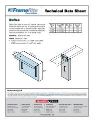
Deflex Clip . . . . . . . . . . . . . . . . . . . . . . . . . . . . .5<br />
DWSC Seismic Clip . . . . . . . . . . . . . . . . . . . . . .5<br />
Exterior Slotted Track (EXT) . . . . . . . . . . . . . . .6<br />
Framing Plate (LTP5) . . . . . . . . . . . . . . . . . . . .21<br />
Grommet . . . . . . . . . . . . . . . . . . . . . . . . . . . . .25<br />
Gusset Plate (Unpunched) (GP) . . . . . . . . . . . . .17<br />
Holdown (S/HD & S/HDS) . . . . . . . . . . . . . . . .14<br />
Katz Blocking (KB) . . . . . . . . . . . . . . . . . . . . . .24<br />
LA Clip (Large Utility Clip) . . . . . . . . . . . . . . . .10<br />
Ledger Connector System (ICFVL) . . . . . . . . . .21<br />
Outrigger . . . . . . . . . . . . . . . . . . . . . . . . . . . . . .3<br />
Reinforcing & Skewable Angle (LS) . . . . . . . . .19<br />
Rigid Clip Connector (RCC) . . . . . . . . . . . . . . . .12<br />
Rigid Clip Connector with HDW Washer . . . . . .13<br />
S/BA Hanger . . . . . . . . . . . . . . . . . . . . . . . . . .20<br />
S/LBV Hanger . . . . . . . . . . . . . . . . . . . . . . . . .20<br />
Seismic & Hurricane Tie (S/H) . . . . . . . . . . . . .16<br />
Seismic & Hurricane Tie (S/H1A) . . . . . . . . . . .15<br />
Solid Blocking (JB) . . . . . . . . . . . . . . . . . . . . . .18<br />
Steel Joist Hanger (S/HJCT) . . . . . . . . . . . . . .22<br />
Strap Tie (ST/LSTA/MST/MSTA) . . . . . . . . . . .17<br />
Tension Bridging (TB) . . . . . . . . . . . . . . . . . . . .24<br />
TABLE OF CONTENTS<br />
DEFLECTION CONNECTORS<br />
WSC Slide Clips . . . . . . . . . . . . . . . . . . . . . . . . . . . . . . . . .2<br />
Outrigger . . . . . . . . . . . . . . . . . . . . . . . . . . . . . . . . . . . . . . .3<br />
WSC 950 & WSC 1500 . . . . . . . . . . . . . . . . . . . . . . . . . . . .4<br />
Deflex Clip . . . . . . . . . . . . . . . . . . . . . . . . . . . . . . . . . . . . . .5<br />
DWSC Seismic Clip . . . . . . . . . . . . . . . . . . . . . . . . . . . . . . .5<br />
RIGID CONNECTORS<br />
Utility Clip (UA) 16 Gauge . . . . . . . . . . . . . . . . . . . . . . . . .6<br />
Utility Clip (UA) 14 Gauge . . . . . . . . . . . . . . . . . . . . . . . . .7<br />
Utility Clip (UA) 12 Gauge . . . . . . . . . . . . . . . . . . . . . . . . .8<br />
LA Clip (Large Utility Clip) . . . . . . . . . . . . . . . . . . . . . . . . .9<br />
Utility Clip (UA & LA) . . . . . . . . . . . . . . . . . . . . . . . . . . . .10<br />
Rigid Clip Connector (RCC) . . . . . . . . . . . . . . . . . . . . . . . .11<br />
Rigid Clip Connector with HDW Washer . . . . . . . . . . . . .12<br />
Holdown (S/HD & S/HDS) . . . . . . . . . . . . . . . . . . . . . . . . .13<br />
Tension Tie (S/LTT & S/HTT) . . . . . . . . . . . . . . . . . . . . . .13<br />
WRC Rigid Clip . . . . . . . . . . . . . . . . . . . . . . . . . . . . . . . . .14<br />
ROOF & TRUSS CONNECTORS<br />
Seismic & Hurricane Tie (S/H1A) . . . . . . . . . . . . . . . . . . .15<br />
Seismic & Hurricane Tie (S/H) . . . . . . . . . . . . . . . . . . . . .16<br />
Twist Strap (MTS) . . . . . . . . . . . . . . . . . . . . . . . . . . . . . .16<br />
Gusset Plate (Unpunched) (GP) . . . . . . . . . . . . . . . . . . . .17<br />
Strap Tie (ST/LSTA/MST/MSTA) . . . . . . . . . . . . . . . . . . .17<br />
JOIST FRAMING CONNECTORS<br />
Solid Blocking (JB) . . . . . . . . . . . . . . . . . . . . . . . . . . . . . .18<br />
Web Stiffener (JS) . . . . . . . . . . . . . . . . . . . . . . . . . . . . . .18<br />
Reinforcing & Skewable Angle (LS) . . . . . . . . . . . . . . . .19<br />
Coiled Strap (CS) . . . . . . . . . . . . . . . . . . . . . . . . . . . . . . . .19<br />
S/LBV Hanger . . . . . . . . . . . . . . . . . . . . . . . . . . . . . . . . . .20<br />
S/BA Hanger . . . . . . . . . . . . . . . . . . . . . . . . . . . . . . . . . . .20<br />
Ledger Connector System (ICFVL) . . . . . . . . . . . . . . . . . .21<br />
Framing Plate (LTP5) . . . . . . . . . . . . . . . . . . . . . . . . . . . .21<br />
Steel Joist Hanger (S/HJCT) . . . . . . . . . . . . . . . . . . . . . .22<br />
BRIDGING & BRACING CONNECTORS<br />
Bridgerite Clip (BR) . . . . . . . . . . . . . . . . . . . . . . . . . . . . . .23<br />
Coiled Strap (CS) . . . . . . . . . . . . . . . . . . . . . . . . . . . . . . . .23<br />
Katz Blocking (KB) . . . . . . . . . . . . . . . . . . . . . . . . . . . . . .24<br />
Tension Bridging (TB) . . . . . . . . . . . . . . . . . . . . . . . . . . . .24<br />
SPECIALTY PRODUCTS<br />
Breakaway Clip (BA) . . . . . . . . . . . . . . . . . . . . . . . . . . . . .25<br />
Grommet . . . . . . . . . . . . . . . . . . . . . . . . . . . . . . . . . . . . . .25<br />
U-Flex Track . . . . . . . . . . . . . . . . . . . . . . . . . . . . . . . . . . .26<br />
Tension Tie (S/LTT & S/HTT) . . . . . . . . . . . . . .14<br />
Twist Strap (MTS) . . . . . . . . . . . . . . . . . . . . . .16<br />
U-Flex Track . . . . . . . . . . . . . . . . . . . . . . . . . .26<br />
Utility Clip (UA & LA) . . . . . . . . . . . . . . . . . . . .11<br />
Utility Clip (UA) 12 Gauge . . . . . . . . . . . . . . . . .9<br />
Utility Clip (UA) 14 Gauge . . . . . . . . . . . . . . . . .8<br />
Utility Clip (UA) 16 Gauge . . . . . . . . . . . . . . . . .7<br />
Web Stiffener (JS) . . . . . . . . . . . . . . . . . . . . . .18<br />
WRC Rigid Clip . . . . . . . . . . . . . . . . . . . . . . . . .15<br />
WSC 950 & WSC 1500 . . . . . . . . . . . . . . . . . . .4<br />
WSC Slide Clips . . . . . . . . . . . . . . . . . . . . . . . . .2<br />
1
Deflection <strong>Connectors</strong><br />
2<br />
<strong>FrameRite</strong> <strong>Connectors</strong><br />
DEFLECTION CONNECTORS<br />
WSC SLIDE CLIP<br />
WSC Slide clips connect exterior curtainwall studs to the building structure and allow for vertical<br />
movement of the building independent of the studs. The new WSC series allows for 3” total deflection,<br />
1-1/2” up and 1-1/2” down. WSC series 14 ga. clips come with extended leg lengths and shouldered<br />
screws are provided in each box of clips. 25 pieces per box.<br />
MATERIAL: See Table<br />
FINISH: Galvanized – G90<br />
Part No. Ga/Mil Material Finish Size<br />
WSC362 14ga (68) 50 KSI G-90 4” x 1.5” x 3.5”<br />
WSC600 14ga (68) 50 KSI G-90 4” x 1.5” x 5.5”<br />
WSC800 14ga (68) 50 KSI G-90 4” x 1.5” x 7.5”<br />
WSC1000 14ga (68) 50 KSI G-90 4” x 1.5” x 9.5”<br />
WSC1200 14ga (68) 50 KSI G-90 4” x 1.5” x 11.5”<br />
CONCENTRIC TENSION (lbs.)<br />
# Screws<br />
2<br />
3<br />
4<br />
5<br />
# Screws<br />
2<br />
3<br />
4<br />
5<br />
110 –#14 Shouldered screws included per box.<br />
*(Note: WSC362 includes 55 - #14 shouldered screws per box)<br />
33 mil<br />
376<br />
564<br />
752<br />
940<br />
33 mil<br />
376<br />
564<br />
752<br />
940<br />
CFS Member<br />
43 mil 54 mil<br />
560 652<br />
840 978<br />
1120 1304<br />
1400 1559<br />
CONCENTRIC COMPRESSION (lbs.)<br />
CFS Member<br />
43 mil 54 mil<br />
560 652<br />
840 966<br />
966 966<br />
966 966<br />
WSC1200<br />
(10 slots)<br />
68 mil<br />
652<br />
978<br />
1304<br />
1559<br />
68 mil<br />
652<br />
966<br />
966<br />
966<br />
WSC1000<br />
(8 slots)<br />
# Screws<br />
2<br />
3<br />
4<br />
5<br />
33 mil<br />
376<br />
564<br />
752<br />
940<br />
WSC800<br />
(6 slots)<br />
ECCENTRIC TENSION (lbs.)<br />
# Screws<br />
2<br />
3<br />
4<br />
5<br />
33 mil<br />
376<br />
564<br />
752<br />
788<br />
CFS Member<br />
43 mil 54 mil<br />
560 652<br />
840 978<br />
1120 1304<br />
1315 1315<br />
ECCENTRIC COMPRESSION (lbs.)<br />
CFS Member<br />
43 mil 54 mil<br />
560 652<br />
788 788<br />
788 788<br />
788 788<br />
Notes:<br />
1. Allowable loads have not been increased for wind or seismic.<br />
2. Attachment of WSC clip to main structure should be engineered by a design professional for steel or concrete base materials.<br />
3. Allowable loads are based on attachment to main structure through pilot holes with #10-24 cap screws with a head diameter of 0.29”.<br />
4. Safety factor, Ω, determined in accordance with the provision of section F1.2 of the NASPEC with statistical data specified in AC261 and from test data.<br />
5. The serviceability limit of 1/8” deflection between the stud and supporting structure did not govern in testing.<br />
6. Eccentric tension and compression values represent clip capacity after structure deflects +_ 1-1/2” up or down from center of the clip.<br />
68 mil<br />
652<br />
978<br />
1304<br />
1315<br />
www.MarinoWare.com<br />
WSC600<br />
(4 slots)<br />
68 mil<br />
652<br />
788<br />
788<br />
788<br />
WSC362*<br />
(2 slots)
<strong>FrameRite</strong> <strong>Connectors</strong><br />
DEFLECTION CONNECTORS<br />
OUTRIGGER<br />
Outrigger Slide Clip is used for horizontal surface applications and offers the highest capacity of any<br />
horizontal surface connection clip. The outrigger comes in lengths of 18”, can be field cut to shorter<br />
lengths if needed. Simple and fast to install which saves time and money. One clip fits all stud sizes,<br />
no right or left hand clips.<br />
2”<br />
MATERIAL: 16 ga (54 mil) 50ksi.<br />
FINISH: Galvanized – G90<br />
DEFLECTION: 1-1/2” Total<br />
55 - #10 Shouldered screws<br />
provided per box<br />
Model<br />
No.<br />
Gauge<br />
(Mil) Yield<br />
Box<br />
Quantity<br />
Outrigger 16 (54) 50ksi 25<br />
20ga. (33 mil) 33ksi 2<br />
20ga. (33 mil) 33ksi 4<br />
18ga. (43 mil) 33ksi 2<br />
18ga (43 mil) 33ksi 4<br />
16ga. (54 mil) 33ksi 2<br />
16ga. (54 mil) 33ksi 4<br />
16ga. (54 mil) 50ksi 2<br />
16ga. (54 mil) 50ksi 4<br />
14ga. (68 mil) 50ksi 2<br />
14ga. (68 mil) 50ksi 4<br />
1-1/2”<br />
Connection to Structure Hilti 0.145” X-EDNI Powder<br />
Actuated Fastener in 3/16” Steel<br />
Thickness<br />
(mil/ga)<br />
No. of<br />
Screws<br />
No. of<br />
Anchors<br />
Allowable<br />
Load (lbs.)<br />
2 278<br />
3 278<br />
4 278<br />
2 484<br />
3 557<br />
4 557<br />
2 413<br />
3 413<br />
4 413<br />
2 483<br />
3 775<br />
4 827<br />
2 483<br />
3 580<br />
4 580<br />
2 483<br />
3 775<br />
4 910<br />
2 483<br />
3 740<br />
4 740<br />
2 483<br />
3 775<br />
4 910<br />
2 483<br />
3 740<br />
4 740<br />
2 783<br />
3 783<br />
4 910<br />
Notes:<br />
1. All anchors must be attached in a single file line down the center of the clip.<br />
2. All anchor data is from the Hilti 2006 Product Technical Guide.<br />
3. All anchors must be attached to structure per manufacturer’s instructions.<br />
4. Anchor Spacing for 2 and 3 anchors to be min. 2”.<br />
5. Anchor Spacing for 4 anchors to be 1” min.<br />
6. Anchor edge distance to be 1/2”min.<br />
18”<br />
Connection to Structure #12-14 Hilti kwik Pro<br />
Self Drilling Screws to 3/16” Steel<br />
Thickness<br />
(mils/ga)<br />
No. of<br />
Screws<br />
20ga. (33 mil) 33ksi 2<br />
20ga. (33 mil) 33ksi 4<br />
18ga. (43 mil) 33ksi 2<br />
18ga (43 mil) 33ksi 4<br />
16ga. (54 mil) 33ksi 2<br />
16ga. (54 mil) 33ksi 4<br />
16ga. (54 mil) 50ksi 2<br />
16ga. (54 mil) 50ksi 4<br />
14ga. (68 mil) 50ksi 2<br />
14ga. (68 mil) 50ksi 4<br />
3”<br />
No. of<br />
Anchors<br />
Allowable<br />
Load (lbs.)<br />
2 278<br />
3 278<br />
4 278<br />
2 557<br />
3 557<br />
4 557<br />
2 413<br />
3 413<br />
4 413<br />
2 590<br />
3 827<br />
4 827<br />
2 580<br />
3 580<br />
4 580<br />
2 590<br />
3 595<br />
4 1075<br />
2 590<br />
3 742<br />
4 742<br />
2 590<br />
3 985<br />
4 1075<br />
2 590<br />
3 742<br />
4 742<br />
2 590<br />
3 985<br />
4 1075<br />
www.MarinoWare.com<br />
Deflection <strong>Connectors</strong> 3
Deflection <strong>Connectors</strong><br />
4<br />
<strong>FrameRite</strong> <strong>Connectors</strong><br />
DEFLECTION CONNECTORS<br />
WSC 950 & WSC 1500<br />
WSC 950 and 1500 Slide Clips provide lateral support for steel studs and allow for vertical movement of the building structure. They allow for<br />
1-3/4” edge of slab tolerance from the existing supporting structure. The WSC Clips accommodate up to 3/4” vertical movement at intermediate<br />
floors and 1-1/2” vertical movement at roof levels. They are used in a vertical surface application. Simple and fast to install which saves time<br />
and money. One clip fits all stud sizes, no right or left hand clips. Screws must be backed out 1/4 turn once installed.<br />
MATERIAL: See Table<br />
FINISH: Galvanized – G90<br />
Model<br />
No.<br />
Gauge (Mil)<br />
Yield<br />
Box<br />
Quantity<br />
WSC950 16 (54) 50ksi 25<br />
WSC1500 12 (97) 40ksi 25<br />
Screws not included for WSC1500 or WSC950<br />
4”<br />
2”<br />
www.MarinoWare.com<br />
Connection to Structure Hilti 0.145” X-EDNI<br />
Connection to Structure Hilti #12-14 Hilti Kwik<br />
Powder Actuated Fastener in 3/16” Steel<br />
Pro Self Drilling Screws to 3/16” Steel<br />
WSC 950 WSC 1500 WSC 950 WSC 1500<br />
Stud<br />
Thickness<br />
# of Screws<br />
to Stud<br />
# of Anchors<br />
to Structure<br />
Allowable<br />
Load (lbs.)<br />
Allowable<br />
Load (lbs.)<br />
Stud<br />
Thickness<br />
Number of<br />
Screws<br />
Number of<br />
Anchors<br />
Allowable<br />
Load (lbs.)<br />
Allowable<br />
Load (lbs.)<br />
20ga. (33 mil)<br />
33ksi<br />
4<br />
2<br />
3<br />
4<br />
220<br />
335<br />
445<br />
220<br />
335<br />
445<br />
20ga. (33 mil)<br />
33ksi<br />
4<br />
2<br />
3<br />
4<br />
500<br />
557<br />
557<br />
555<br />
555<br />
555<br />
20ga. (33 mil)<br />
33ksi<br />
6<br />
2<br />
3<br />
4<br />
220<br />
335<br />
445<br />
220<br />
335<br />
445<br />
20ga. (33 mil)<br />
33ksi<br />
6<br />
2<br />
3<br />
4<br />
500<br />
750<br />
835<br />
770<br />
835<br />
835<br />
18ga. (43 mil)<br />
33ksi<br />
4<br />
2<br />
3<br />
4<br />
220<br />
335<br />
445<br />
220<br />
335<br />
445<br />
18ga. (43 mil)<br />
33ksi<br />
4<br />
2<br />
3<br />
4<br />
500<br />
750<br />
827<br />
770<br />
824<br />
824<br />
18ga. (43 mil)<br />
33ksi<br />
6<br />
2<br />
3<br />
4<br />
220<br />
335<br />
445<br />
220<br />
335<br />
445<br />
18ga. (43 mil)<br />
33ksi<br />
6<br />
2<br />
3<br />
4<br />
500<br />
750<br />
945<br />
770<br />
1150<br />
1240<br />
16ga. (54 mil)<br />
33ksi<br />
4<br />
2<br />
3<br />
4<br />
220<br />
335<br />
445<br />
220<br />
335<br />
445<br />
16ga. (54 mil)<br />
33ksi<br />
4<br />
2<br />
3<br />
4<br />
500<br />
750<br />
945<br />
770<br />
1150<br />
1480<br />
16ga. (54 mil)<br />
33ksi<br />
6<br />
2<br />
3<br />
4<br />
220<br />
335<br />
445<br />
220<br />
335<br />
445<br />
16ga. (54 mil)<br />
33ksi<br />
6<br />
2<br />
3<br />
4<br />
500<br />
750<br />
945<br />
770<br />
1150<br />
1480<br />
16ga. (54 mil)<br />
50ksi<br />
4<br />
2<br />
3<br />
4<br />
220<br />
335<br />
445<br />
220<br />
335<br />
445<br />
16ga. (54 mil)<br />
50ksi<br />
4<br />
2<br />
3<br />
4<br />
500<br />
750<br />
945<br />
770<br />
1150<br />
1480<br />
16ga. (54 mil)<br />
50ksi<br />
6<br />
2<br />
3<br />
4<br />
220<br />
335<br />
445<br />
220<br />
335<br />
445<br />
16ga. (54 mil)<br />
50ksi<br />
6<br />
2<br />
3<br />
4<br />
500<br />
750<br />
945<br />
770<br />
1150<br />
1495<br />
14ga. (68 mil)<br />
50ksi<br />
4<br />
2<br />
3<br />
4<br />
220<br />
335<br />
445<br />
220<br />
335<br />
445<br />
14ga. (68 mil)<br />
50ksi<br />
4<br />
2<br />
3<br />
4<br />
500<br />
750<br />
945<br />
770<br />
1150<br />
1480<br />
14ga. (68 mil)<br />
50ksi<br />
Notes:<br />
6<br />
2<br />
3<br />
4<br />
220<br />
335<br />
445<br />
220<br />
335<br />
445<br />
14ga. (68 mil)<br />
50ksi<br />
6<br />
2<br />
3<br />
4<br />
500<br />
750<br />
945<br />
770<br />
1150<br />
1495<br />
1. All anchors must be attached in a single file line down the center of the clip, do not use predrilled holes if attaching with PAF.<br />
2. All anchor data is from the Hilti 2006 Product Technical Guide.<br />
3. All anchors must be attached to structure per manufacturer’s instructions.<br />
4. All manufacturer’s guidelines must be followed for anchor spacing and edge distance.<br />
4-1/2”
<strong>FrameRite</strong> <strong>Connectors</strong><br />
DEFLECTION CONNECTORS<br />
DEFLEX CLIP®<br />
Deflex Clips® allow up to 1-1/2” vertical floor or roof deflection without the use of laborious slip tracks it<br />
can be installed with or without standard leg tracks. Simple and fast to install which saves time and<br />
money. Two sizes available for 3-5/8”, 4”, 6” and 8” studs.<br />
MATERIAL: 16 ga (54 mil) 50ksi.<br />
FINISH: Galvanized – G90<br />
• 3T1000 accommodates 3-5/8” and 4” stud widths<br />
• 6T1000 accommodates 6” and 8” stud widths<br />
Model<br />
No.<br />
Gauge (Mil)<br />
Yield<br />
Box<br />
Quantity<br />
3T1000 16 (54) 50 ksi 25<br />
6T1000 16 (54) 50 ksi 25<br />
Stud<br />
Thickness<br />
1-1/2”<br />
Connection to Structure Hilti 0.145” X-EDNI<br />
Powder Actuated Fastener in 3/16” Steel<br />
Deflex Deflex<br />
3T1000 6T1000<br />
# of Screws<br />
to Stud<br />
# of Anchors<br />
to Structure<br />
Allowable<br />
Load (lbs.)<br />
Allowable<br />
Load (lbs.)<br />
Stud<br />
Thickness<br />
2-7/8”<br />
or 5-1/4”<br />
4-1/2”<br />
Connectin to Structure #12-14 Hilti Kwik<br />
Pro Self Drilling Screws to 3/16” Steel<br />
Deflex<br />
3T1000<br />
Number of<br />
Screws<br />
Number of<br />
Anchors<br />
Allowable<br />
Load (lbs.)<br />
www.MarinoWare.com<br />
Deflex<br />
6T1000<br />
Allowable<br />
Load (lbs.)<br />
20ga. (33 mil)<br />
33ksi<br />
2<br />
2<br />
3<br />
224<br />
228<br />
276<br />
276<br />
20ga. (33 mil)<br />
33ksi<br />
2<br />
2<br />
3<br />
278<br />
278<br />
278<br />
278<br />
18ga. (43 mil)<br />
33ksi<br />
2<br />
2<br />
3<br />
224<br />
228<br />
413<br />
413<br />
18ga. (43 mil)<br />
33ksi<br />
2<br />
2<br />
3<br />
410<br />
410<br />
413<br />
413<br />
16ga. (54 mil)<br />
33ksi<br />
2<br />
2<br />
3<br />
224<br />
228<br />
413<br />
440<br />
16ga. (54 mil)<br />
33ksi<br />
2<br />
2<br />
3<br />
455<br />
495<br />
580<br />
580<br />
16ga. (54 mil)<br />
50ksi<br />
2<br />
2<br />
3<br />
224<br />
228<br />
413<br />
440<br />
16ga. (54 mil)<br />
50ksi<br />
2<br />
2<br />
3<br />
455<br />
495<br />
685<br />
742<br />
14ga. (68 mil)<br />
50ksi<br />
Notes:<br />
2<br />
2<br />
3<br />
224<br />
228<br />
413<br />
440<br />
14ga. (68 mil)<br />
50ksi<br />
2<br />
2<br />
3<br />
455<br />
495<br />
685<br />
742<br />
1. All anchors must be attached in a single file line down the center of the clip.<br />
2. All anchor data is from the Hilti 2006 Product Technical Guide.<br />
3. All anchors must be attached to structure per manufacturer’s instructions.<br />
4. Anchor edge distance to be 1/2” min.<br />
DWSC SEISMIC CLIP<br />
The DWSC series of clips allow for vertical and lateral movement of the<br />
building structure independent of the studs. The DWSC has a total of 3”<br />
vertical deflection and total of 2” lateral movement and uses shouldered<br />
screws which are included for ease of installation. 25 pieces per box.<br />
Part No. Ga/Mil Material Finish Size<br />
DWSC362 14ga (68) 50 KSI G-90 4” x 2.5” x 3.5”<br />
DWSC600 14ga (68) 50 KSI G-90 4” x 2.5” x 5.5”<br />
DWSC800 14ga (68) 50 KSI G-90 4” x 2.5” x 7.5”<br />
DWSC1000 14ga (68) 50 KSI G-90 4” x 2.5” x 9.5”<br />
DWSC1200 14ga (68) 50 KSI G-90 4” x 2.5” x 11.5”<br />
110 –#14 Shouldered screws included per box.<br />
*(Note: DWSC362 includes 55 - #14 shouldered screws per box)<br />
DWSC1200<br />
(10 slots)<br />
DWSC1000<br />
(8 slots)<br />
DWSC800<br />
(6 slots)<br />
DWSC600<br />
(4 slots)<br />
55 - #10<br />
Shouldered screws<br />
included<br />
DWSC362*<br />
(2 slots)<br />
5<br />
Deflection <strong>Connectors</strong>
Rigid <strong>Connectors</strong><br />
6<br />
<strong>FrameRite</strong> <strong>Connectors</strong><br />
RIGID CONNECTORS<br />
UTILITY CLIP (UA) - 16 GAUGE<br />
Utility Clips are used in a variety of framing applications including floors,<br />
walls and roofs. UA clips are pre-cut with pre-drilled holes for easy installation.<br />
• Leg lengths available from 3-1/4” through 15-3/4”. (See table for exact sizes)<br />
• Leg widths available in 1-1/2”, 2”, 3” and 4”.<br />
• Available in 16, 14 and 12 gauge.<br />
• Pre-punched for faster and more accurate fastener attachment.<br />
• 3”x 3” Clips available (do not have embossments) See page 12<br />
MATERIAL: See Table for sizes – 50ksi<br />
FINISH: Galvanized – G90<br />
INSTALLATION:<br />
• Utility Clips are attached to the cold formed steel (CFS) framing members<br />
using #10 - 16 self-drilling screws; using pre-punched holes.<br />
1-1/2”, 2”,<br />
3”, & 4”<br />
Utility Clips<br />
1-1/2” & 2”<br />
UA Clips - 16 Gauge Allowable Load (lbs)<br />
Model No. Thickness<br />
(mil/ga)<br />
Size<br />
(in.)<br />
Box<br />
Qty Screws<br />
UA-113-16 54 (16 ga) 1-1/2 x 1-1/2 x 3-1/4 100 3-#10<br />
UA-223-16 54 (16 ga) 2 x 2 x 3-1/4 100 3-#10<br />
UA-133-16 54 (16 ga) 1-1/2 x 3 x 3-1/4 100 3-#10<br />
UA-143-16 54 (16 ga) 1-1/2 x 4 x 3-1/4 100 3-#10<br />
UA-115-16 54 (16 ga) 1-1/2 x 1-1/2 x 5-1/4 100 3-#10<br />
UA-225-16 54 (16 ga) 2 x 2 x 5-1/4 50 3-#10<br />
UA-135-16 54 (16 ga) 1-1/2 x 3 x 5-1/4 50 3-#10<br />
UA-145-16 54 (16 ga) 1-1/2 x 4 x 5-1/4 50 3-#10<br />
UA-118-16 54 (16 ga) 1-1/2 x 1-1/2 x 7-3/4 50 5-#10<br />
UA-228-16 54 (16 ga) 2 x 2 x 7-3/4 50 5-#10<br />
UA-138-16 54 (16 ga) 1-1/2 x 3 x 7-3/4 25 5-#10<br />
UA-148-16 54 (16 ga) 1-1/2 x 4 x 7-3/4 25 5-#10<br />
UA-119-16 54 (16 ga) 1-1/2 x 1-1/2 x 9 50 5-#10<br />
UA-229-16 54 (16 ga) 2 x 2 x 9 50 5-#10<br />
UA-139-16 54 (16 ga) 1-1/2 x 3 x 9 25 5-#10<br />
UA-149-16 54 (16 ga) 1-1/2 x 4 x 9 25 5-#10<br />
UA-1110-16 54 (16 ga) 1-1/2 x 1-1/2 x 9-3/4 50 5-#10<br />
UA-2210-16 54 (16 ga) 2 x 2 x 9-3/4 50 5-#10<br />
UA-1310-16 54 (16 ga) 1-1/2 x 3 x 9-3/4 25 5-#10<br />
UA-1410-16 54 (16 ga) 1-1/2 x 4 x 9-3/4 25 5-#10<br />
UA-1112-16 54 (16 ga) 1-1/2 x 1-1/2 x 11-3/4 50 7-#10<br />
UA-2212-16 54 (16 ga) 2 x 2 x 11-3/4 50 7-#10<br />
UA-1312-16 54 (16 ga) 1-1/2 x 3 x 11-3/4 25 7-#10<br />
UA-1412-16 54 (16 ga) 1-1/2 x 4 x 11-3/4 25 7-#10<br />
UA-1114-16 54 (16 ga) 1-1/2 x 1-1/2 x 13-3/4 50 9-#10<br />
UA-2214-16 54 (16 ga) 2 x 2 x 13-3/4 50 9-#10<br />
UA-1314-16 54 (16 ga) 1-1/2 x 3 x 13-3/4 25 9-#10<br />
UA-1414-16 54 (16 ga) 1-1/2 x 4 x 13-3/4 25 9-#10<br />
UA-1116-16 54 (16 ga) 1-1/2 x 1-1/2 x 15-3/4 50 9-#10<br />
UA-2216-16 54 (16 ga) 2 x 2 x 15-3/4 25 9-#10<br />
UA-1316-16 54 (16 ga) 1-1/2 x 3 x 15-3/4 25 9-#10<br />
UA-1416-16 54 (16 ga) 1-1/2 x 4 x 15-3/4 25 9-#10<br />
20ga (33 mil)<br />
33 ksi<br />
18ga (43 mil)<br />
33 ksi<br />
*Hole pattern measurements<br />
are available on page 15.<br />
16ga (54 mil)<br />
33 ksi<br />
16ga (54 mil)<br />
50 ksi<br />
www.MarinoWare.com<br />
14ga (68 mil)<br />
50 ksi<br />
12ga (97 mil)<br />
50 ksi<br />
F1 F2 F1 F2 F1 F2 F1 F2 F1 F2 F1 F2<br />
686 380 907 462 907 546 1313 546 1589 644 1589 644<br />
686 380 907 462 907 546 1313 546 1589 644 1589 644<br />
562 380 562 462 562 546 722 546 722 644 722 644<br />
495 380 489 462 489 546 489 546 489 644 489 644<br />
686 435 907 645 907 882 1313 882 1589 1040 1589 1040<br />
686 435 907 645 907 882 1313 882 1589 1040 1589 1040<br />
562 435 562 645 562 882 722 882 722 1040 722 1040<br />
495 435 489 645 489 882 489 882 489 1040 489 1040<br />
1143 725 1512 1075 1512 1302 2188 1302 2649 1535 2649 1535<br />
1143 725 1512 1075 1512 1302 2188 1302 2649 1535 2649 1535<br />
1143 725 1512 1075 1512 1302 2188 1302 2562 1535 2562 1535<br />
1143 725 1468 1075 1468 1302 1468 1302 1468 1535 1468 1535<br />
1143 725 1512 1075 1512 1512 2188 1512 2649 1782 2649 1782<br />
1143 725 1512 1075 1512 1512 2188 1512 2649 1782 2649 1782<br />
1143 725 1512 1075 1512 1512 2188 1512 2562 1782 2562 1782<br />
1143 725 1512 1075 1512 1512 2188 1512 2377 1782 2377 1782<br />
1143 725 1512 1075 1512 1515 2188 1638 2649 1795 2649 1795<br />
1143 725 1512 1075 1512 1515 2188 1638 2649 1795 2649 1795<br />
1143 725 1512 1075 1512 1515 2188 1638 2562 1795 2562 1795<br />
1143 725 1512 1075 1512 1515 2188 1638 2377 1795 2377 1795<br />
1600 1015 2116 1505 2116 1974 3063 1974 3709 2327 3709 2327<br />
1600 1015 2116 1505 2116 1974 3063 1974 3709 2327 3709 2327<br />
1600 1015 2116 1505 2116 1974 3063 1974 3586 2327 3586 2327<br />
1600 1015 2116 1505 2116 1974 3063 1974 3328 2327 3328 2327<br />
2057 1305 2721 1935 2721 2310 3938 2310 4768 2723 4768 2723<br />
2057 1305 2721 1935 2721 2310 3938 2310 4768 2723 4768 2723<br />
2057 1305 2721 1935 2721 2310 3938 2310 4611 2723 4611 3231<br />
2057 1305 2721 1935 2721 2310 3938 2310 4279 2723 4279 3231<br />
2057 1305 2721 1935 2721 2646 3938 2646 4768 3119 4768 3119<br />
2057 1305 2721 1935 2721 2646 3938 2646 4768 3119 4768 3119<br />
2057 1305 2721 1935 2721 2646 3938 2646 4611 3119 4611 3119<br />
2057 1305 2721 1935 2721 2646 3938 2646 4279 3119 4279 3119<br />
Notes:<br />
1. Allowable loads have not been increased for wind or seismic.<br />
2. Allowable strength shown is the lowest value from the four failure modes: screw tilting/bearing, screw shear, screw pull-over and the serviceability limit state of 1/8" deflection of CFS members.<br />
3. It is the responsibility of design professional to design the connection of UA connectors to the supporting structure. In the test program, this connection was made with cap screws with a head diameter of 0.29".<br />
The allowable loads should be conservative for any fastener with a header diameter equal to or greater than 0.29".<br />
4. F1=Shear, F2=Tension
<strong>FrameRite</strong> <strong>Connectors</strong><br />
RIGID CONNECTORS<br />
UTILITY CLIP (UA) - 14 GAUGE<br />
Utility Clips are used in a variety of framing applications including floors, walls<br />
and roofs. UA clips are pre-cut with pre-drilled holes for easy installation.<br />
• Leg lengths available from 3-1/4” through 15-3/4”. (See table for exact sizes)<br />
• Leg widths available in 1-1/2”, 2”, 3” and 4”.<br />
• Available in 16, 14 and 12 gauge.<br />
• Pre-punched for faster and more accurate fastener attachment.<br />
• 3”x 3” Clips available (do not have embossments) See page 12<br />
MATERIAL: See Table for sizes – 50ksi<br />
FINISH: Galvanized – G90<br />
INSTALLATION:<br />
• Utility Clips are attached to the cold formed steel (CFS) framing members<br />
using #10 - 16 self-drilling screws; using pre-punched holes.<br />
1-1/2”, 2“,<br />
3”, & 4”<br />
Utility Clips *Hole pattern measurements<br />
are available on page 15.<br />
1-1/2” & 2”<br />
UA Clips - 14 Gauge Allowable Load (lbs)<br />
Model No. Thickness<br />
(mil/ga)<br />
Size<br />
(in.)<br />
Box<br />
Qty Screws<br />
UA-113-14 68 (14 ga) 1-1/2 x 1-1/2 x 3-1/4 100 3-#10<br />
UA-223-14 68 (14 ga) 2 x 2 x 3-1/4 100 3-#10<br />
UA-133-14 68 (14 ga) 1-1/2 x 3 x 3-1/4 100 3-#10<br />
UA-143-14 68 (14 ga) 1-1/2 x 4 x 3-1/4 100 3-#10<br />
UA-115-14 68 (14 ga) 1-1/2 x 1-1/2 x 5-1/4 100 3-#10<br />
UA-225-14 68 (14 ga) 2 x 2 x 5-1/4 50 3-#10<br />
UA-135-14 68 (14 ga) 1-1/2 x 3 x 5-1/4 50 3-#10<br />
UA-145-14 68 (14 ga) 1-1/2 x 4 x 5-1/4 50 3-#10<br />
UA-118-14 68 (14 ga) 1-1/2 x 1-1/2 x 7-3/4 50 5-#10<br />
UA-228-14 68 (14 ga) 2 x 2 x 7-3/4 50 5-#10<br />
UA-138-14 68 (14 ga) 1-1/2 x 3 x 7-3/4 25 5-#10<br />
UA-148-14 68 (14 ga) 1-1/2 x 4 x 7-3/4 25 5-#10<br />
UA-119-14 68 (14 ga) 1-1/2 x 1-1/2 x 9 50 5-#10<br />
UA-229-14 68 (14 ga) 2 x 2 x 9 50 5-#10<br />
UA-139-14 68 (14 ga) 1-1/2 x 3 x 9 25 5-#10<br />
UA-149-14 68 (14 ga) 1-1/2 x 4 x 9 25 5-#10<br />
UA-1110-14 68 (14 ga) 1-1/2 x 1-1/2 x 9-3/4 50 5-#10<br />
UA-2210-14 68 (14 ga) 2 x 2 x 9-3/4 50 5-#10<br />
UA-1310-14 68 (14 ga) 1-1/2 x 3 x 9-3/4 25 5-#10<br />
UA-1410-14 68 (14 ga) 1-1/2 x 4 x 9-3/4 25 5-#10<br />
UA-1112-14 68 (14 ga) 1-1/2 x 1-1/2 x 11-3/4 50 7-#10<br />
UA-2212-14 68 (14 ga) 2 x 2 x 11-3/4 50 7-#10<br />
UA-1312-14 68 (14 ga) 1-1/2 x 3 x 11-3/4 25 7-#10<br />
UA-1412-14 68 (14 ga) 1-1/2 x 4 x 11-3/4 25 7-#10<br />
UA-1114-14 68 (14 ga) 1-1/2 x 11/2 x 13-3/4 50 9-#10<br />
UA-2214-14 68 (14 ga) 2 x 2 x 13-3/4 50 9-#10<br />
UA-1314-14 68 (14 ga) 1-1/2 x 3 x 13-3/4 25 9-#10<br />
UA-1414-14 68 (14 ga) 1-1/2 x 4 x 13-3/4 25 9-#10<br />
UA-1116-14 68 (14 ga) 1-1/2 x 1-1/2 x 1-53/4 50 9-#10<br />
UA-2216-14 68 (14 ga) 2 x 2 x 15-3/4 25 9-#10<br />
UA-1316-14 68 (14 ga) 1-1/2 x 3 x 15-3/4 25 9-#10<br />
UA-1416-14 68 (14 ga) 1-1/2 x 4 x 15-3/4 25 9-#10<br />
20ga (33 mil)<br />
33 ksi<br />
18ga (43 mil)<br />
33 ksi<br />
16ga (54 mil)<br />
33 ksi<br />
16ga (54 mil)<br />
50 ksi<br />
www.MarinoWare.com<br />
F1<br />
14ga (68 mil)<br />
50 ksi<br />
12ga (97 mil)<br />
50 ksi<br />
F1 F2 F1 F2 F1 F2 F1 F2 F1 F2 F1 F2<br />
686 435 907 645 907 861 1313 861 1589 920 1589 920<br />
686 435 907 645 907 861 1313 861 1589 920 1589 920<br />
562 435 562 645 562 861 722 861 722 920 722 920<br />
495 435 489 645 489 861 489 861 489 920 489 920<br />
686 435 907 645 907 909 1313 1290 1589 1290 1589 1290<br />
686 435 907 645 907 909 1313 1290 1589 1290 1589 1290<br />
562 435 562 645 562 909 722 1290 722 1290 722 1290<br />
495 435 489 645 489 909 489 1290 489 1290 489 1290<br />
1143 725 1512 1075 1512 1515 2188 2054 2649 2150 2649 2150<br />
1143 725 1512 1075 1512 1515 2188 2054 2649 2150 2649 2150<br />
1143 725 1512 1075 1512 1515 2188 2054 2562 2150 2562 2150<br />
1143 725 1468 1075 1468 1515 1468 2054 1468 2150 1468 2150<br />
1143 725 1512 1075 1512 1515 2188 2150 2649 2150 2649 2150<br />
1143 725 1512 1075 1512 1515 2188 2150 2649 2150 2649 2150<br />
1143 725 1512 1075 1512 1515 2188 2150 2562 2150 2562 2150<br />
1143 725 1512 1075 1512 1515 2188 2150 2377 2150 2377 2150<br />
1143 725 1512 1075 1512 1515 2188 2150 2649 2150 2649 2150<br />
1143 725 1512 1075 1512 1515 2188 2150 2649 2150 2649 2150<br />
1143 725 1512 1075 1512 1515 2188 2150 2562 2150 2562 2150<br />
1143 725 1512 1075 1512 1515 2188 2150 2377 2150 2377 2150<br />
1600 1015 2116 1505 2116 2121 3063 3010 3709 3010 3709 3010<br />
1600 1015 2116 1505 2116 2121 3063 3010 3709 3010 3709 3010<br />
1600 1015 2116 1505 2116 2121 3063 3010 3586 3010 3586 3010<br />
1600 1015 2116 1505 2116 2121 3063 3010 3328 3010 3328 3010<br />
2057 1305 2721 1935 2721 2727 3938 3644 4768 3870 4768 3870<br />
2057 1305 2721 1935 2721 2727 3938 3644 4768 3870 4768 3870<br />
2057 1305 2721 1935 2721 2727 3938 3644 4611 3870 4611 3870<br />
2057 1305 2721 1935 2721 2727 3938 3644 4279 3870 4279 3870<br />
2057 1305 2721 1935 2721 2727 3938 3870 4768 3870 4768 3870<br />
2057 1305 2721 1935 2721 2727 3938 3870 4768 3870 4768 3870<br />
2057 1305 2721 1935 2721 2727 3938 3870 4611 3870 4611 3870<br />
2057 1305 2721 1935 2721 2727 3938 3870 4279 3870 4279 3870<br />
Notes:<br />
1. Allowable loads have not been increased for wind or seismic.<br />
2. Allowable strength shown is the lowest value from the four failure modes: screw tilting/bearing, screw shear, screw pull-over and the serviceability limit state of 1/8" deflection of CFS members.<br />
3. It is the responsibility of design professional to design the connection of UA connectors to the supporting structure. In the test program, this connection was made with cap screws with a head diameter of 0.29".<br />
The allowable loads should be conservative for any fastener with a header diameter equal to or greater than 0.29".<br />
4. F1=Shear, F2=Tension<br />
F2<br />
Rigid <strong>Connectors</strong><br />
7
Rigid <strong>Connectors</strong><br />
8<br />
<strong>FrameRite</strong> <strong>Connectors</strong><br />
RIGID CONNECTORS<br />
UTILITY CLIP (UA) - 12 GAUGE<br />
Utility Clips are used in a variety of framing applications including floors, walls<br />
and roofs. UA clips are pre-cut with pre-drilled holes for easy installation.<br />
• Leg lengths available from 3-1/4” through 15-3/4”. (See table for exact sizes)<br />
• Leg widths available in 1-1/2”, 2”, 3” and 4”.<br />
• Available in 16, 14 and 12 gauge.<br />
• Pre-punched for faster and more accurate fastener attachment.<br />
• 3”x 3” Clips available (do not have embossments) See page 12<br />
MATERIAL: See Table for sizes – 50ksi<br />
FINISH: Galvanized – G90<br />
INSTALLATION:<br />
• Utility Clips are attached to the cold formed steel (CFS) framing members<br />
using #10 - 16 self-drilling screws; using pre-punched holes.<br />
Utility Clips *Hole pattern measurements<br />
are available on page 15.<br />
1-1/2”, 2“,<br />
3”, & 4”<br />
1-1/2” & 2”<br />
UA Clips - 12 Gauge Allowable Load (lbs)<br />
Model No. Thickness<br />
(mil/ga)<br />
Size<br />
(in.)<br />
Box<br />
Qty Screws<br />
UA-113-12 97 (12 ga) 1-1/2 x 1-1/2 x 3-1/4 100 3-#10<br />
UA-223-12 97 (12 ga) 2 x 2 x 3-1/4 100 3-#10<br />
UA-133-12 97 (12 ga) 1-1/2 x 3 x 3-1/4 100 3-#10<br />
UA-143-12 97 (12 ga) 1-1/2 x 4 x 3-1/4 50 3-#10<br />
UA-115-12 97 (12 ga) 1-1/2 x 1-1/2 x 5-1/4 100 3-#10<br />
UA-225-12 97 (12 ga) 2 x 2 x 5-1/4 50 3-#10<br />
UA-135-12 97 (12 ga) 1-1/2 x 3 x 5-1/4 50 3-#10<br />
UA-145-12 97 (12 ga) 11/2 x 4 x 51/4 50 3-#10<br />
UA-118-12 97 (12 ga) 1-1/2 x 1-1/2 x 7-3/4 50 5-#10<br />
UA-228-12 97 (12 ga) 2 x 2 x 7-3/4 50 5-#10<br />
UA-138-12 97 (12 ga) 1-1/2 x 3 x 7-3/4 25 5-#10<br />
UA-148-12 97 (12 ga) 1-1/2 x 4 x 7-3/4 25 5-#10<br />
UA-119-12 97 (12 ga) 1-1/2 x 1-1/2 x 9 50 5-#10<br />
UA-229-12 97 (12 ga) 2 x 2 x 9 25 5-#10<br />
UA-139-12 97 (12 ga) 1-1/2 x 3 x 9 25 5-#10<br />
UA-149-12 97 (12 ga) 1-1/2 x 4 x 9 25 5-#10<br />
UA-1110-12 97 (12 ga) 1-1/2 x 1-1/2 x 9-3/4 50 5-#10<br />
UA-2210-12 97 (12 ga) 2 x 2 x 9-3/4 25 5-#10<br />
UA-1310-12 97 (12 ga) 1-1/2 x 3 x 9-3/4 25 5-#10<br />
UA-1410-12 97 (12 ga) 1-1/2 x 4 x 9-3/4 25 5-#10<br />
UA-1112-12 97 (12 ga) 1-1/2 x 1-1/2 x 1-13/4 25 7-#10<br />
UA-2212-12 97 (12 ga) 2 x 2 x 11-3/4 25 7-#10<br />
UA-1312-12 97 (12 ga) 1-1/2 x 3 x 11-3/4 25 7-#10<br />
UA-1412-12 97 (12 ga) 1-1/2 x 4 x 11-3/4 25 7-#10<br />
UA-1114-12 97 (12 ga) 1-1/2 x 1-1/2 x 13-3/4 25 9-#10<br />
UA-2214-12 97 (12 ga) 2 x 2 x 13-3/4 25 9-#10<br />
UA-1314-12 97 (12 ga) 1-1/2 x 3 x 13-3/4 15 9-#10<br />
UA-1414-12 97 (12 ga) 1-1/2 x 4 x 13-3/4 15 9-#10<br />
UA-1116-12 97 (12 ga) 1-1/2 x 1-1/2 x 15-3/4 25 9-#10<br />
UA-2216-12 97 (12 ga) 2 x 2 x 15-3/4 15 9-#10<br />
UA-1316-12 97 (12 ga) 1-1/2 x 3 x 15-3/4 15 9-#10<br />
UA-1416-12 97 (12 ga) 1-1/2 x 4 x 15-3/4 15 9-#10<br />
20ga (33 mil)<br />
33 ksi<br />
18ga (43 mil)<br />
33 ksi<br />
16ga (54 mil)<br />
33 ksi<br />
16ga (54 mil)<br />
50 ksi<br />
www.MarinoWare.com<br />
14ga (68 mil)<br />
50 ksi<br />
12ga (97 mil)<br />
50 ksi<br />
F1 F2 F1 F2 F1 F2 F1 F2 F1 F2 F1 F2<br />
686 435 907 645 907 909 1313 1290 1589 1290 1589 1290<br />
686 435 907 645 907 909 1313 1290 1589 1290 1589 1290<br />
686 435 907 645 907 909 1313 1290 1537 1290 1537 1290<br />
686 435 907 645 907 909 1313 1290 1426 1290 1426 1290<br />
686 435 907 645 907 909 1313 1290 1589 1290 1589 1290<br />
686 435 907 645 907 909 1313 1290 1589 1290 1589 1290<br />
686 435 907 645 907 909 1313 1290 1537 1290 1537 1290<br />
686 435 907 645 907 909 1313 1290 1426 1290 1426 1290<br />
1143 725 1512 1075 1512 1515 2188 2150 2649 2150 2649 2150<br />
1143 725 1512 1075 1512 1515 2188 2150 2649 2150 2649 2150<br />
1143 725 1512 1075 1512 1515 2188 2150 2562 2150 2562 2150<br />
1143 725 1512 1075 1512 1515 2188 2150 2377 2150 2377 2150<br />
1143 725 1512 1075 1512 1515 2188 2150 2649 2150 2649 2150<br />
1143 725 1512 1075 1512 1515 2188 2150 2649 2150 2649 2150<br />
1143 725 1512 1075 1512 1515 2188 2150 2562 2150 2562 2150<br />
1143 725 1512 1075 1512 1515 2188 2150 2377 2150 2377 2150<br />
1143 725 1512 1075 1512 1515 2188 2150 2649 2150 2649 2150<br />
1143 725 1512 1075 1512 1515 2188 2150 2649 2150 2649 2150<br />
1143 725 1512 1075 1512 1515 2188 2150 2562 2150 2562 2150<br />
1143 725 1512 1075 1512 1515 2188 2150 2377 2150 2377 2150<br />
1600 1015 2116 1505 2116 2121 3063 3010 3709 3010 3709 3010<br />
1600 1015 2116 1505 2116 2121 3063 3010 3709 3010 3709 3010<br />
1600 1015 2116 1505 2116 2121 3063 3010 3586 3010 3586 3010<br />
1600 1015 2116 1505 2116 2121 3063 3010 3328 3010 3328 3010<br />
2057 1305 2721 1935 2721 2727 3938 3870 4768 3870 4768 3870<br />
2057 1305 2721 1935 2721 2727 3938 3870 4768 3870 4768 3870<br />
2057 1305 2721 1935 2721 2727 3938 3870 4611 3870 4611 3870<br />
2057 1305 2721 1935 2721 2727 3938 3870 4279 3870 4279 3870<br />
2057 1305 2721 1935 2721 2727 3938 3870 4768 3870 4768 3870<br />
2057 1305 2721 1935 2721 2727 3938 3870 4768 3870 4768 3870<br />
2057 1305 2721 1935 2721 2727 3938 3870 4611 3870 4611 3870<br />
2057 1305 2721 1935 2721 2727 3938 3870 4279 3870 4279 3870<br />
Notes:<br />
1. Allowable loads have not been increased for wind or seismic.<br />
2. Allowable strength shown is the lowest value from the four failure modes: screw tilting/bearing, screw shear, screw pull-over and the serviceability limit state of 1/8" deflection of CFS members.<br />
3. It is the responsibility of design professional to design the connection of UA connectors to the supporting structure. In the test program, this connection was made with cap screws with a head diameter of 0.29".<br />
The allowable loads should be conservative for any fastener with a header diameter equal to or greater than 0.29".<br />
4. F1=Shear, F2=Tension
<strong>FrameRite</strong> <strong>Connectors</strong><br />
RIGID CONNECTORS<br />
LA CLIP (LARGE UTILITY CLIP)<br />
The LA series of clip angles is a series of rigid clips used in a variety<br />
of framing applications. Pre-drilled for ease of installation.<br />
MATERIAL: See table for sizes – 50ksi<br />
FINISH: Galvanized – G90<br />
3”x 3” LA Clips<br />
Model<br />
No.<br />
Size<br />
(in.)<br />
Box<br />
Qty<br />
LA333-16 3 x 3 x 3-1/4 100<br />
LA333-14 3 x 3 x 3-1/4 100<br />
LA333-12 3 x 3 x 3-1/4 50<br />
LA335-16 3 x 3 x 5-1/4 50<br />
LA335-14 3 x 3 x 5-1/4 50<br />
LA335-12 3 x 3 x 5-1/4 50<br />
LA338-16 3 x 3 x 7-3/4 25<br />
LA338-14 3 x 3 x 7-3/4 25<br />
LA338-12 3 x 3 x 7-3/4 25<br />
1/2”<br />
2-1/8”<br />
Model No.<br />
LA-333-16 54 (16 GA) 3" x 3" x 3-1/4" 6 - #10<br />
LA-333-14 68 (14 GA) 3" x 3" x 3-1/4" 6 - #10<br />
LA-333-12 97 (12 GA) 3" x 3" x 3-1/4" 6 - #10<br />
LA-335-16 54 (16 GA) 3" x 3" x 5-1/4" 6 - #10<br />
LA-335-14 68 (14 GA) 3" x 3" x 5-1/4" 6 - #10<br />
LA-335-12 97 (12 GA) 3" x 3" x 5-1/4" 6 - #10<br />
LA-338-16 54 (16 GA) 3" x 3" x 7-3/4" 6 - #10<br />
LA-338-14 68 (14 GA) 3" x 3" x 7-3/4" 6 - #10<br />
LA-338-12 97 (12 GA) 3" x 3" x 7-3/4" 6 - #10<br />
Thickness<br />
(mil/ga)<br />
Size<br />
(in.) Screws<br />
3”<br />
LA335<br />
3”<br />
2-1/8”<br />
1/2”<br />
LA333<br />
5-1/4”<br />
3/4”<br />
1-1/2”<br />
3/4”<br />
LA338<br />
LA Clips Allowable Load (lbs)<br />
3”<br />
3”<br />
1/2”<br />
1-1/8”<br />
1-1/8”<br />
1/2”<br />
www.MarinoWare.com<br />
20ga (33 mil) 18ga (43 mil) 16ga (54 mil) 16ga (54 mil) 14ga (68 mil) 12ga (97 mil)<br />
33 ksi 33 ksi 33 ksi 50 ksi 50 ksi 50 ksi<br />
Shear Tension Shear Tension Shear Tension Shear Tension Shear Tension Shear Tension<br />
562 380 562 462 562 546 722 546 722 644 722 644<br />
562 602 562 689 562 861 722 861 722 920 722 920<br />
562 870 562 1160 562 1515 722 1515 722 1495 722 1495<br />
562 614 562 746 562 882 722 882 722 1040 722 1040<br />
562 870 562 1113 562 1391 722 1391 722 1486 722 1486<br />
562 870 562 1290 562 1818 722 2447 722 2415 722 2415<br />
1372 870 1814 1077 1814 1077 2625 1077 3074 1077 3074 1077<br />
1372 870 1814 1290 1814 1818 2625 2054 3074 2193 3074 2193<br />
1372 870 1814 1290 1814 1818 2625 2580 3074 2580 3074 2580<br />
Notes:<br />
1. Allowable loads have not been increased for wind or seismic.<br />
2. Allowable strength shown is the lowest value from the four failure modes: screw tilting/bearing, screw shear, screw pull-over and the serviceability limit state of 1/8" deflection of CFS members.<br />
3. It is the responsibility of design professional to design the connection of UA connectors to the supporting structure. In the test program, this connection was made with cap screws with a head diameter of 0.29".<br />
The allowable loads should be conservative for any fastener with a header diameter equal to or greater than 0.29".<br />
3-1/4”<br />
3/4”<br />
1-1/2”<br />
1/2”<br />
3/4”<br />
3”<br />
3-3/8”<br />
3”<br />
3-3/8”<br />
1/2”<br />
7-3/4”<br />
3/4”<br />
1-1/2”<br />
3/4”<br />
Rigid <strong>Connectors</strong> 9
Rigid <strong>Connectors</strong><br />
10<br />
<strong>FrameRite</strong> <strong>Connectors</strong><br />
RIGID CONNECTORS<br />
UTILITY CLIP (UA & LA)<br />
1-1/2” x 1-1/2” Angle<br />
Length<br />
No. of<br />
Holes<br />
3-1/4” 6<br />
5-1/4” 6<br />
7-3/4” 10<br />
9” 10<br />
9-3/4” 10<br />
11-3/4” 14<br />
13-3/4” 18<br />
15-3/4” 18<br />
2” x 2” Angle<br />
Length<br />
No. of<br />
Holes<br />
3-1/4” 6<br />
5-1/4” 6<br />
7-3/4” 10<br />
9” 10<br />
9-3/4” 10<br />
11-3/4” 14<br />
13-3/4” 18<br />
15-3/4” 18<br />
3” x 3” Angle<br />
Length<br />
No. of<br />
Holes<br />
3-1/4” 12<br />
5-1/4” 12<br />
7-3/4” 12<br />
1/2”<br />
1/2”<br />
1/2”<br />
1-1/2”<br />
2”<br />
3”<br />
1-1/2”<br />
2-1/8”<br />
2”<br />
3”<br />
2-1/8”<br />
1/2”<br />
1/2”<br />
1/2”<br />
3/4”<br />
3/4”<br />
1/2”<br />
3/4”<br />
1-1/4”<br />
1-1/2”<br />
3/4”<br />
3/4”<br />
1/2”<br />
3/4”<br />
3/4”<br />
1-1/4”<br />
3/4”<br />
1-1/2” x 4” Angle<br />
Length<br />
No. of<br />
Holes<br />
3-1/4” 12<br />
5-1/4” 12<br />
7-3/4” 20<br />
9” 20<br />
9-3/4” 20<br />
11-3/4” 28<br />
13-3/4” 36<br />
15-3/4” 36<br />
1-1/2” x 3” Angle<br />
Length<br />
No. of<br />
Holes<br />
3-1/4” 9<br />
5-1/4” 9<br />
7-3/4” 15<br />
9” 15<br />
9-3/4” 15<br />
11-3/4” 21<br />
13-3/4” 27<br />
15-3/4” 27<br />
1/2”<br />
1/2”<br />
F1<br />
1-1/2”<br />
1-1/2”<br />
4”<br />
3”<br />
www.MarinoWare.com<br />
1/2”<br />
1/2”<br />
F2<br />
3/4”<br />
3/4”<br />
1/2”<br />
1/2”<br />
3/4”<br />
3/4”<br />
3/4”<br />
1-1/4”<br />
1-1/4”<br />
3/4”<br />
3/4”<br />
1-1/2”<br />
3/4”
<strong>FrameRite</strong> <strong>Connectors</strong><br />
RIGID CONNECTORS<br />
RIGID CLIP CONNECTOR (RCC)<br />
Rigid Clip <strong>Connectors</strong> (RCC) are used to rigidly attach the bottom of<br />
a parapet stud to the structure, or where high tension or rotational<br />
restrain is required.<br />
MATERIAL: 12ga (97 mil), 50 ksi<br />
FINISH: Galvanized G90<br />
INSTALLATION:<br />
• Attach long leg of Rigid Clip Connector to web of stud<br />
with #10–16 screws through pre-punched holes.<br />
• Attach short leg of Rigid Clip Connector to structure<br />
with a 1/2” anchor bolt per Project Engineer’s design.<br />
Allowable Strength of RCC in Moment (M1)<br />
Allowable Strength (in-kips)<br />
CFS Member<br />
Flexibility (Rad/in-lb x10<br />
RCC358 RCC600 RCC800<br />
Thickness Fy No. of Screws No. of Screws No. of Screws<br />
(mils/ga) (ksi) 3 6 3 6 5 10<br />
33 (20) 33<br />
0.82<br />
29.3<br />
1.51<br />
17.4<br />
1.79<br />
7.28<br />
2.29<br />
5.9<br />
2.78<br />
8.21<br />
3.00<br />
2.92<br />
43 (18) 33<br />
0.82<br />
29.3<br />
1.51<br />
17.4<br />
1.79<br />
7.28<br />
2.29<br />
5.9<br />
2.78<br />
8.21<br />
3.00<br />
2.92<br />
54 (16) 50<br />
1.43<br />
29.3<br />
1.51<br />
17.4<br />
3.23<br />
7.28<br />
3.23<br />
5.9<br />
3.46<br />
8.21<br />
5.91<br />
2.92<br />
68 (14) 50<br />
1.43<br />
29.3<br />
2.32<br />
17.4<br />
3.22<br />
7.28<br />
3.22<br />
5.9<br />
3.46<br />
8.21<br />
5.71<br />
2.92<br />
97 (12) 50<br />
1.43<br />
29.3<br />
2.32<br />
17.4<br />
3.22<br />
7.28<br />
3.22<br />
5.9<br />
3.46<br />
8.21<br />
5.71<br />
2.92<br />
6 )<br />
Allowable Strength of RCC in Tension/Compression (F2)<br />
4"<br />
CFS Member<br />
Thickness<br />
(mils/ga)<br />
3-1/4"<br />
Fy<br />
(ksi)<br />
33 (20) 33<br />
43 (18) 33<br />
54 (16) 50<br />
68 (14) 50<br />
97 (12) 50<br />
RCC358 & RCC600<br />
with 3 screws pattern<br />
RCC358<br />
Allowable Strength (lbs)<br />
RCC600 RCC800<br />
No. of Screws No. of Screws No. of Screws<br />
3 6 3 6 5 10<br />
530 1,060 530 1,060 884 1,767<br />
789 1,578 789 1,578 1,315 2,116<br />
1,602 2,116 1,602 2,116 2,116 2,116<br />
1,640 2,116 1,640 2,116 2,116 2,116<br />
1,640 2,116 1,640 2,116 2,116 2,116<br />
4"<br />
5-1/4"<br />
RCC358 & RCC600<br />
with 6 screws pattern<br />
4"<br />
3.25”<br />
5.25”<br />
7.75”<br />
Rigid Clip Connector (RCC)<br />
Model<br />
No.<br />
Stud<br />
Size<br />
Dimensions<br />
(in.)<br />
Box<br />
Quantity<br />
RCC358 3-5/8” 1-1/2 x 4 x 3-1/4 50<br />
RCC600 6” 1-1/2 x 4 x 5-1/4 50<br />
RCC800 8” 1-1/2 x 4 x 7-3/4 25<br />
Allowable Strength of RCC in Shear (F1)<br />
CFS Member<br />
Thickness<br />
(mils/ga)<br />
7-3/4"<br />
RCC800<br />
with 5 screws pattern<br />
RCC Clip<br />
1.50”<br />
4.0”<br />
4"<br />
www.MarinoWare.com<br />
M1<br />
RCC Loading<br />
Conditions<br />
RCC358<br />
Allowable Strength (lbs)<br />
RCC600 RCC800<br />
No. of Screws No. of Screws No. of Screws<br />
3 6 3 6 5 10<br />
450 450 600 710 850 850<br />
450 450 600 710 850 850<br />
840 1,000 1,250 1,500 1,860 1,990<br />
840 1,000 1,250 1,500 1,860 1,990<br />
840 1,000 1,250 1,500 1,860 1,990<br />
Notes:<br />
1. Tabulated values are based on #10-16 screws with ultimate shear capacity of 1,600 lbs per screw.<br />
2. Allowable loads have not been increased for wind or seismic.<br />
3. Tabulated loads are based on 1/2” diameter bolt with 1/2” Type A plain washer with a nominal outside diameter of 1.062” & nominal thickness of 0.095”.<br />
4. It is the responsibility of the design professional to design the connection of the RCC to the supporting structure.<br />
5. Use linear interaction for combination of F1, F2, and M1.<br />
6. The 1/4” thick Heavy Duty Washer (HDW) meets ASTM A36 Standard Specification for Carbon Structural Steel and is made from hot rolled flat bar and painted gray for corrosion resistance.<br />
Fy<br />
(ksi)<br />
33 (20) 33<br />
43 (18) 33<br />
54 (16) 50<br />
68 (14) 50<br />
97 (12) 50<br />
7-3/4"<br />
RCC800<br />
with 10 screws pattern<br />
11<br />
Rigid <strong>Connectors</strong>
Rigid <strong>Connectors</strong><br />
12<br />
<strong>FrameRite</strong> <strong>Connectors</strong><br />
RIGID CONNECTORS<br />
RIGID CLIP CONNECTOR WITH HDW WASHER<br />
Rigid Clip <strong>Connectors</strong> (RCC) are used to rigidly attach the bottom of a parapet stud to the<br />
structure, or where high tension or rotational restrain is required.<br />
MATERIAL: 1/4” Carbon Structural Steel Hot Rolled Heavy Duty Washer (HDW), 36 ksi<br />
FINISH: HDW washer is painted gray for corrosion resistance.<br />
INSTALLATION:<br />
• Attach long leg of Rigid Clip Connector to web of stud with<br />
#10–16 screws through pre-punched holes.<br />
• Attach short leg of Rigid Clip Connector to structure with a<br />
1/2” anchor bolt per Project Engineer’s design.<br />
Allowable Strength of RCC with HDW (Washer) in Moment (M1)<br />
Allowable Strength (in-kips)<br />
CFS Member<br />
Flexibility (Rad/in-lb x10<br />
RCC358 RCC600 RCC800<br />
Thickness<br />
(mil/ga)<br />
Fy<br />
(ksi)<br />
No. of Screws<br />
3 6<br />
No. of Screws<br />
3 6<br />
No. of Screws<br />
5 10<br />
33 (20) 33<br />
0.99<br />
28.4<br />
1.94<br />
8.07<br />
2.15<br />
4.06<br />
2.35<br />
4.06<br />
3.37<br />
6.39<br />
3.82<br />
1.7<br />
43 (18) 33<br />
0.99<br />
28.4<br />
1.94<br />
8.07<br />
2.15<br />
4.06<br />
2.35<br />
4.06<br />
3.37<br />
6.39<br />
3.82<br />
1.7<br />
54 (16) 50<br />
2.10<br />
28.4<br />
3.99<br />
8.07<br />
4.38<br />
4.06<br />
4.69<br />
4.06<br />
8.06<br />
6.39<br />
8.03<br />
1.7<br />
68 (14) 50<br />
2.10<br />
28.4<br />
3.99<br />
8.07<br />
4.38<br />
4.06<br />
4.69<br />
4.06<br />
8.06<br />
6.39<br />
8.03<br />
1.7<br />
97 (12) 50<br />
2.10<br />
28.4<br />
3.99<br />
8.07<br />
4.38<br />
4.06<br />
4.69<br />
4.06<br />
8.06<br />
6.39<br />
8.03<br />
1.7<br />
6 )<br />
Allowable Strength with HDW (Washer) in Shear (F1)<br />
4"<br />
CFS Member<br />
Thickness<br />
(mils/Ga)<br />
Fy<br />
(ksi)<br />
33 (20) 33<br />
43 (18) 33<br />
54 (16) 50<br />
68 (14) 50<br />
97 (12) 50<br />
3-1/4"<br />
RCC358 & RCC600<br />
with 3 screws pattern<br />
RCC358<br />
Allowable Strength (lbs)<br />
RCC600 RCC800<br />
No. of Screws No. of Screws No. of Screws<br />
3 6 3 6 5 10<br />
480 480 660 760 980 980<br />
480 480 660 760 980 980<br />
1,070 1,100 1,450 1,670 2,160 2,160<br />
1,070 1,100 1,450 1,670 2,160 2,160<br />
1,070 1,100 1,450 1,670 2,160 2,160<br />
4"<br />
5-1/4"<br />
RCC358 & RCC600<br />
with 6 screws pattern<br />
4"<br />
HDW<br />
CFS Member<br />
Thickness<br />
(mils/Ga)<br />
7-3/4"<br />
3.25”<br />
5.25”<br />
7.75”<br />
Heavy Duty Washer (HDW)<br />
RCC800<br />
with 5 screws pattern<br />
RCC Clip<br />
with HDW<br />
9 /16” Dia. Hole<br />
Notes:<br />
1. Tabulated values are based on #10-16 screws with ultimate shear capacity of 1,600 lbs per screw.<br />
2. Allowable loads have not been increased for wind or seismic.<br />
3. Tabulated loads are based on 1/2” diameter bolt with 1/2” Type A plain washer with a nominal outside diameter of 1.062” & nominal thickness of 0.095”.<br />
4. It is the responsibility of the design professional to design the connection of the RCC to the supporting structure.<br />
5. Use linear interaction for combination of F1, F2, and M1.<br />
6. The 1/4” thick Heavy Duty Washer (HDW) meets ASTM A36 Standard Specification for Carbon Structural Steel and is made from hot rolled flat bar and painted gray for corrosion resistance.<br />
Fy<br />
(ksi)<br />
33 (20) 33<br />
43 (18) 33<br />
54 (16) 50<br />
68 (14) 50<br />
97 (12) 50<br />
4"<br />
0.25”<br />
1.3125”<br />
Model<br />
No.<br />
Stud<br />
Size<br />
Dimensions<br />
(in.)<br />
Box<br />
Quantity<br />
HDW358 3-5/8” 1/4 x 1-5/16 x 3-1/4 50<br />
HDW600 6” 1/4 x 1-5/16 x 5-1/4 50<br />
HDW800 8” 1/4 x 1-5/16 x 7-3/4 25<br />
www.MarinoWare.com<br />
7-3/4"<br />
4.0”<br />
1.50”<br />
Allowable Strength with HDW (Washer) in Tension/Compression (F2)<br />
RCC358<br />
Allowable Strength (lbs)<br />
RCC600 RCC800<br />
No. of Screws No. of Screws No. of Screws<br />
3 6 3 6 5 10<br />
530 1,060 530 1,060 884 1,767<br />
789 1,578 789 1,578 1,315 2,630<br />
1,602 3,205 1,602 2,219 2,671 3,244<br />
1,640 3,244 1,640 3,205 2,733 3,244<br />
1,640 3,244 1,640 3,244 2,733 3,244<br />
RCC800<br />
with 10 screws pattern
<strong>FrameRite</strong> <strong>Connectors</strong><br />
RIGID CONNECTORS<br />
HOLDOWN (S/HD & S/HDS)<br />
The S/HD series of holdowns is designed for installation with either screws or bolts into the studs or column. The<br />
S/HDS series installs with #14 screws and has been designed to utilize fewer fasteners to reduce installation time.<br />
The S/HDB series is ideal for bolt-on applications where the cold-formed stud manufacturer can re-punch the bolt holes.<br />
MATERIAL: S/HD8 and S/HD10 – 118 mil (10 ga) with 3/8” plate, S/HD15 – 171 mil (7 ga) with 1/2” plate.<br />
FINISH: Simpson gray paint. Hot-dip galvanized is available.<br />
INSTALLATION:<br />
• Use all specified fasteners.<br />
• The design engineer may specify any alternate anchorage calculated<br />
to resist the tension load for your specific job.<br />
• Anchor bolt washer is not required.<br />
Model<br />
No.<br />
Dimensions (in.)<br />
W H CL<br />
S/HD8 2-1/2 13-7/8 1-1/2 7/8 24-#10 7615 8460 8940 0.085<br />
S/HD10 2-1/2 16-1/8 1-1/2 7/8 30-#10 9520 9665 9665 0.093<br />
S/HD15 2-3/4 21-1/2 1-1/2 1 48-#10 – 12200 14405 0.070<br />
S/HD8S 2-5/16 11 1-1/2 7/8 17-#14 8580 11070 11070 0.0695<br />
S/HD10S 2-5/16 13-1/2 1-1/2 7/8 22-#14 8580 11120 12200 0.0960<br />
S/HD15S 2-7/16 17 1-3/8 1 30-#14 8580 11120 13500 0.0970<br />
TENSION TIE (S/LTT & S/HTT)<br />
Fasteners<br />
Anchor<br />
Dia. Screws<br />
Notes:<br />
1. For load at (100), multiply table value by 0.75 where the 1/3 increase is not permitted.<br />
2. Values are test limited. For load at (100), no reduction necessary. For load at (133) for 1/3 increase, no further increase allowed.<br />
3. The Designer shall specify the anchor embedment and configuration.<br />
4. Deflection at Highest allowable Design Load: The deflection of a holdown measured between the anchor bolt and the strap portion of<br />
the holdown when loaded to the highest allowable load listed in the catalog table. This movement is strictly due to the holdown<br />
deformation under a static load test conducted on a steel jig.<br />
The S/HTT14 is a single-piece formed tension tie–no rivets, and a 4-ply<br />
formed seat which won’t unfold during loading. No washers are required.<br />
The S/LTT and S/HTT Tension Ties are ideal for retrofit or new construction<br />
projects. They provide high strength, post-pour, concrete-to-steel connections.<br />
MATERIAL: See table.<br />
FINISH: Galvanized – G90<br />
INSTALLATION:<br />
• Use all specified fasteners.<br />
• Use the specified number and type of screws to attach the strap portion<br />
to the steel stud. Bolt the base to the wall or foundation with a suitable<br />
anchor; see table for the required bolt diameter.<br />
Model<br />
No.<br />
Material (mil/ga)<br />
Strap Plate<br />
Allowable Tension Loads (133)<br />
Back-to-Back Stud Holdown Deflection<br />
2–33 mil.<br />
(2–20 ga.)<br />
2–43 mil<br />
(2–18 ga.)<br />
2–54 mil<br />
(2–16 ga.)<br />
at Highest Allowable<br />
Design Load<br />
S/HTT14<br />
Dimensions (in.) Fasteners<br />
Allowable<br />
Tension Holdown Deflection<br />
Anchor<br />
Loads at Highest Allowable<br />
W H CL Bolts Screws (133) Design Load<br />
S/LTT20 97 (12 ga) 229 (3 ga) 2 20 1-1/2 1/2 8 –#10 1600 0.209<br />
S/HTT14 111 (11 ga) – 2-1/2 15 1-1/4 5/8 14 –#10 4325 0.041<br />
Notes:<br />
1. The Designer shall specify the anchor embedment and configuration.<br />
2. Load at (100), no reduction necessary. Load at (133) for 1/3 increase, no further increase allowed.<br />
3. Loads are based on attachment of CFS members having a minimum thickness of 33 mil (20 ga).<br />
4. Deflection at Highest allowable Design Load: The deflection of a holdown measured between the anchor bolt and the strap portion of the<br />
holdown when loaded to the highest allowable load listed in the catalog table. This movement is strictly due to the holdown deformation<br />
under a static load test conducted on a steel jig.<br />
S/LTT20<br />
www.MarinoWare.com<br />
S/HD10<br />
(S/HD10S similar)<br />
S/HD15<br />
13<br />
Rigid <strong>Connectors</strong>
Rigid <strong>Connectors</strong><br />
14<br />
<strong>FrameRite</strong> <strong>Connectors</strong><br />
RIGID CONNECTORS<br />
WRC RIGID CLIP<br />
The WRC series of clips connects exterior studs to the building structure and resists horizontal<br />
and lateral loads. The WRC has embossments and a continuous flange to allow for excellent<br />
load values. 25 pieces per box.<br />
Part No. Ga. (Mil)<br />
WRC362 14ga (68)<br />
WRC600 14ga (68)<br />
WRC800 14ga (68)<br />
WRC1000 14ga (68)<br />
WRC1200 14ga (68)<br />
Material<br />
50 KSI<br />
50 KSI<br />
50 KSI<br />
50 KSI<br />
50 KSI<br />
Finish Size<br />
G-90 4” x 1.5” x 3.5”<br />
G-90 4” x 1.5” x 5.5”<br />
G-90 4” x 1.5” x 7.5”<br />
G-90 4” x 1.5” x 9.5”<br />
G-90 4” x 1.5” x 11.5”<br />
WRC1200 WRC1000<br />
WRC800<br />
WRC600<br />
www.MarinoWare.com<br />
WRC362
<strong>FrameRite</strong> <strong>Connectors</strong><br />
ROOF & TRUSS CONNECTORS<br />
SEISMIC & HURRICANE TIE (S/H1A)<br />
S/H1A was designed to fit within several proprietary truss chords<br />
to provide uplift resistance.<br />
MATERIAL: 18 ga (43 mil) 33ksi<br />
FINISH: Galvanized – G90<br />
INSTALLATION:<br />
• Use all specified fasteners.<br />
• S/H1A can be installed with flanges facing outward<br />
(reverse of the illustration) when installed inside a wall<br />
for truss applications.<br />
• S/H1A does not replace solid blocking.<br />
Model<br />
No.<br />
Truss<br />
Fasteners<br />
Top Track<br />
Studs<br />
Truss<br />
Thickness<br />
mil (ga)<br />
Allowable Loads (100)<br />
Plate/Wall Stud Thickness mil (ga)<br />
33 mil (20 ga) 43 mil (18 ga) 54 mil (16 ga)<br />
S/H1A 4-#10 3-#10 1-#10 27 (22 ga) 470 470 470<br />
4-#10 3-#10 1-#10 33 (20 ga) 510 550 690<br />
4-#10 3-#10 1-#10 43 (18 ga) 510 550 690<br />
Notes:<br />
4-#10 3-#10 1-#10 54 (16 ga) 590 675 850<br />
1. Load at (100), no reduction is necessary. Load at (133) for 1/3 increase, no further increase allowed.<br />
2. Loads are based on truss steel properties of Fy=50 ksi and Fu=65 ksi. Reduce load direct proportionally for lower steel strength.<br />
For example: Truss with 43 mil (18 ga) thickness has a steel properties of Fy=33 ksi, Fu=45 ksi and is connected to 43 mil plate<br />
and wall stud. The adjusted allowable load = 550 lbs x minimum [33/50 or 45/65] = 363 lbs.<br />
S/H1A<br />
www.MarinoWare.com<br />
Roof & Truss <strong>Connectors</strong><br />
15
Roof & Truss <strong>Connectors</strong><br />
16<br />
<strong>FrameRite</strong> <strong>Connectors</strong><br />
ROOF & TRUSS CONNECTORS<br />
SEISMIC & HURRICANE TIE (S/H)<br />
Designed to provide seismic and wind ties for trusses or joists, this versatile line may be<br />
used for general tie purposes, strongback attachments, and as all-purpose ties where one<br />
member crosses another.<br />
MATERIAL: 18 ga (43 mil) 33ksi<br />
FINISH: Galvanized – G90<br />
INSTALLATION:<br />
• Use all specified fasteners.<br />
• The S/H1 can be installed with flanges facing outward (reverse of<br />
illustration) when installed inside a wall for truss applications.<br />
• Hurricane Ties do not replace solid blocking<br />
• S/H2.5 ties are only shipped in equal quantities of rights and lefts.<br />
Model<br />
No.<br />
Fasteners<br />
Truss<br />
Thickness<br />
Allowable Tension<br />
Loads (100 & 133)<br />
Lateral<br />
Rafter Plate Stud (mil/ga) Uplift F1 F2<br />
S/H1 3-#10 2-#10 1-#10 43 (18 ga) 265 100 115<br />
S/H2 3-#10 – 3-#10 43 (18 ga) 315 – –<br />
S/H2.5<br />
Notes:<br />
4-#10 – 4-#10 43 (18 ga) 415 90 125<br />
1. Load at (100), no reduction is necessary. Load at (133) for 1/3 increase, no further increase allowed.<br />
2. Loads are based on attachment of cold-formed steel members having a minimum thickness of 33 mil (20 ga).<br />
3. Hurricane Ties are shown installed on the outside of wall for clarity. Installation inside of wall is acceptable.<br />
For Continuous Load Path, connections must be on same side of wall.<br />
TWIST STRAP (MTS)<br />
Typical S/H2<br />
installation<br />
Twist straps provide a tension connection between two members. They resist uplift<br />
at the heel of a truss economically. The 3” bend section eliminates interference at the<br />
transition points between steel members.<br />
MATERIAL: 16 ga (54 mil) 50ksi<br />
FINISH: Galvanized – G90<br />
INSTALLATION:<br />
• Use all specified fasteners.<br />
Model<br />
No.<br />
Material<br />
Thickness<br />
(mil/ga) Length<br />
Fasteners (Total)<br />
Rafter/Stud/Joist Thickness<br />
33 mil 43 mil 54 mil<br />
(20ga) (18ga) (16ga)<br />
Allowable Tension Loads<br />
33 mil (20ga) 43 mil (18ga)<br />
(100) (133) (100) (133)<br />
MTS12 54 (16ga) 12” 12 –#10 8 –#10 5 –#10 995 995 995 995<br />
Notes:<br />
1. All straps have additional fastener holes.<br />
2. Install half of the fasteners on each end of strap to achieve full loads.<br />
3. Load at (100), no reduction necessary. Load at (133) for 1/3 increase, no further increase allowed.<br />
4. All straps have the twist in the center of the strap.<br />
5. Twist straps do not have to be wrapped over the truss to achieve the load.<br />
6. May be installed on the inside face of the stud.<br />
7. Loads are based on steel with 43 mil (18 ga) minimum.<br />
8. Not all fastener holes need to be filled as additional fastener holes provided. Install fasteners symmetrically.<br />
S/H1<br />
MTS12<br />
S/H2<br />
1-1/4”<br />
L<br />
1” Typ.<br />
www.MarinoWare.com<br />
Typical S/H1<br />
installation<br />
S/H2.5<br />
Typical installation<br />
truss to steel studs
<strong>FrameRite</strong> <strong>Connectors</strong><br />
ROOF & TRUSS CONNECTORS<br />
GUSSET PLATE (UNPUNCHED) (GP)<br />
Designed for a variety of construction connections. Used for conditions such as roof, wall and floor<br />
framing connections. GPU Plate is used for in plane truss chord connections, header to jamb connections<br />
and tension strap connections. Adapts to varying construction tolerances.<br />
MATERIAL: See Table, 50ksi<br />
FINISH: Galvanized coating weight as requested.<br />
INSTALLATION:<br />
• As specified by design.<br />
• 16 Gauge (54 mils) .0566” Design Thickness<br />
• 12 Gauge (97 mils) .1017” Design Thickness<br />
• Custom sizes available upon request.<br />
Gusset Plate (Unpunched)<br />
Model<br />
No. Gauge Size<br />
GPU66-16 16 6”x6”<br />
GPU612-16 16 6”x12”<br />
GPU1212-16 16 12”x12”<br />
GPU66-12 12 6”x6”<br />
GPU612-12 12 6”x12”<br />
GPU1212-12 12 12”x12”<br />
STRAP TIE (ST/LSTA/MST/MSTA)<br />
Straps are load rated and provide the correct thickness and number of fasteners the specifier is looking for<br />
compared with the field fabricated straps.<br />
Install Strap Ties where top or bottom plates are cut, at wall intersections, and as ridge ties. LSTA and MSTA<br />
straps are engineered for use on members with a minimum width of 1-1/2”. Reduce the allowable load based on<br />
the size and quantity of fasteners used.<br />
Refer to applicable code for minimum edge and end distances.<br />
S/MST<br />
FINISH: Galvanized – G90<br />
INSTALLATION:<br />
• Use all specified fasteners.<br />
LSTA and MSTA<br />
Model<br />
No.<br />
Material<br />
Thickness<br />
mil (ga)<br />
Dimensions<br />
W L<br />
Fasteners (Total)<br />
Rafter/Stud/Joist Thickness<br />
33 mil (20<br />
ga)<br />
43 mil (18<br />
ga)<br />
Notes:<br />
1. Use half of the fasteners in each member being connected to achieve the listed loads.<br />
2. Loads are based on lesser of steel capacity and fastener calculation.<br />
3. Tabulated loads shown at (100) do not include steel stress increase.<br />
Tabulated loads shown at (133) include a 1/3 stress increase on the steel.<br />
ST<br />
54 mil (16<br />
ga)<br />
33 mil (20 ga)<br />
Allowable Tension Loads<br />
43 mil (18 ga)<br />
www.MarinoWare.com<br />
54 mil (16 ga)<br />
(100) (133) (100) (133) (100) (133)<br />
LSTA24 33 (20 ga) 1-1/4 24 14-#10 12-#10 10-#10 1190 1590 1190 1590 1190 1590<br />
LSTA36 43 (18 ga) 1-1/4 36 18-#10 16-#10 14-#10 1555 2070 1555 2070 1555 2070<br />
MSTA24 43 (18 ga) 1-1/4 24 18-#10 12-#10 10-#10 1555 2070 1555 2070 1555 2070<br />
MSTA36 54 (16 ga) 1-1/4 36 24-#10 18-#10 16-#10 1950 2600 1950 2600 1950 2600<br />
ST6224 54 (16 ga) 2-1/16 23-5/16 28-#10 20-#10 12-#10 2455 3275 2455 3275 2455 3275<br />
ST6236 68 (14 ga) 2-1/16 33-13/16 40-#10 30-#10 18-#10 3535 4715 3760 5015 3760 5015<br />
MST27 97 (12 ga) 2-1/16 27 30-#10 30-#10 22-#10 2650 3535 3945 5260 5025 6700<br />
MST37 97 (12 ga) 2-1/16 37-1/2 42-#10 40-#10 22-#10 3710 4950 5025 6700 5025 6700<br />
Roof & Truss <strong>Connectors</strong><br />
17
Joist Framing <strong>Connectors</strong><br />
18<br />
<strong>FrameRite</strong> <strong>Connectors</strong><br />
JOIST FRAMING CONNECTORS<br />
SOLID BLOCKING (JB)<br />
Joist Blocking is pre-cut to fit securely between joists to prevent joist rotation. Joist Blocking<br />
is a one piece system in lieu of the typical 3 piece detail offering an economical alternative to<br />
installing conventional clips and solid web members.<br />
MATERIAL: 16 ga (54 mil) 50ksi<br />
FINISH: Galvanized – G90<br />
INSTALLATION:<br />
• Position the pre-cut Joist Blocking to fit securely between the joists.<br />
• (4) #10 - 16 screws are required to secure the blocking to the joist flanges using<br />
the pre-punched holes.<br />
• Solid blocking should be installed 7’ o.c. maximum along the joist length.<br />
• Fits up to 2” flange joist product.<br />
• Blocking for 2-1/2” and 3” flanges available as a special order.<br />
Model<br />
No.<br />
Size<br />
Spacing<br />
(o.c.)<br />
Box<br />
Quantity<br />
800JB-12 8” 12 10<br />
925JB-12 9-1/4” 12 10<br />
1000JB-12 10” 12 10<br />
1125JB-12 11-1/4” 12 10<br />
1200JB-12 12” 12 10<br />
1400JB-12 14” 12 10<br />
800JB-16 8” 16 10<br />
925JB-16 9-1/4” 16 10<br />
1000JB-16 10” 16 10<br />
1125JB-16 11-1/4” 16 10<br />
1200JB-16 12” 16 10<br />
1400JB-16 14” 16 10<br />
800JB-24 8” 24 10<br />
925JB-24 9-1/4” 24 10<br />
1000JB-24 10” 24 10<br />
1125JB-24 11-1/4” 24 10<br />
1200JB-24 12” 24 10<br />
1400JB-24 14” 24 10<br />
WEB STIFFENER (JS)<br />
Web Stiffeners are used to provide reinforcement of joist webs to prevent crippling.<br />
Web reinforcement is often required by design to enhance the load capacity of<br />
joists. Web stiffeners are installed on the inside or outside of the joist.<br />
MATERIAL: 16 ga (54 mil) 50ksi<br />
FINISH: Galvanized – G90<br />
INSTALLATION:<br />
• Web stiffeners are centered within the load or reaction bearing width.<br />
• Web stiffeners require full bearing along their supported ends.<br />
• (4-6) #10 - 16 screws are required to attach the stiffener to the joist<br />
web using pre-punched holes.<br />
Model<br />
No. Size<br />
Box<br />
Quantity<br />
8JS-362 8” 24<br />
925JS-362 91/4” 24<br />
10JS-362 10” 24<br />
1125JS-362 111/4” 24<br />
12JS-362 12” 24<br />
14JS-362 14” 24<br />
Solid Blocking<br />
Web Stiffener<br />
www.MarinoWare.com<br />
3-5/8”<br />
Length
<strong>FrameRite</strong> <strong>Connectors</strong><br />
JOIST FRAMING CONNECTORS<br />
REINFORCING & SKEWABLE ANGLE (LS)<br />
LS angles are load rated and provide the correct thickness and number of fasteners the specifier is<br />
looking for compared with field fabricated clip angles. General utility reinforcing angles with multiple<br />
uses. LS—Field-adjustable angles attach members at intersecting angles.<br />
MATERIAL: LS – 18 ga (43 mil) 33ksi<br />
FINISH: Galvanized – G90<br />
INSTALLATION:<br />
• Use all specified fasteners.<br />
• LS—field-skewable; bend one time only.<br />
• Joist must be constrained against rotation when using a single S/LS per connection.<br />
Allowable Loads (100)<br />
Model<br />
No. Length Screws<br />
33 mil (20ga)<br />
F1 F2<br />
43 mil (18ga)<br />
F1<br />
54 mil (16ga)<br />
F1 F1<br />
LS50 4-7/8” 4 – #10 200 – 420 500 –<br />
LS70 6-3/8” 6 – #10 465 – 630 715 –<br />
LS90<br />
Notes:<br />
9” 10 – #10 795 – 1050 1740 –<br />
1. Tabulated loads are governed by tests and may not be increased.<br />
2. Loads are for one part only.<br />
COILED STRAP (CS)<br />
CS are continuous utility straps which can be cut to length on the job site.<br />
Packaged in lightweight (about 40 pounds) cartons.<br />
MATERIAL: 33 mil (20 ga), 43 mil (18 ga) & 54 mil (16 ga)<br />
FINISH: Galvanized – G90<br />
INSTALLATION:<br />
• Use all specified fasteners.<br />
• Refer to the applicable code for minimum edge and end distances.<br />
• The table shows the maximum allowable loads and the screws required to obtain<br />
them. See footnote #1. Fewer screws may be used; reduce the allowable load<br />
by the code lateral load for each fastener subtracted from each end.<br />
Model<br />
No.<br />
Coiled Strap<br />
Length<br />
Material<br />
Thickness<br />
(mil/ga) Width<br />
CS16 150’ 54 (16ga) 1-1/4” 18 –#10 12 –#10 8 –#10 1550 2065<br />
CS18 200’ 43 (18ga) 1-1/4” 14 –#10 10 –#10 6 –#10 1235 1645<br />
CS20 250’ 33 (20ga) 1-1/4” 12 –#10 8 –#10 6 –#10 945 1260<br />
Notes:<br />
1. Use half of the fasteners in each member being connected to achieve the listed loads.<br />
2. For CS straps: End Length (inches) = 1/2 total fasteners + 1”.<br />
3. Total Cut Length = End Length + Clear Span + End Length.<br />
4. For a reduced number of screws, allowable load = (#screws used/#screws in table) x table load.<br />
5. Loads are based on lesser of steel strap capacity and 2001 AISI NASPEC fastener calculation.<br />
6. Tabulated loads shown at (100) do not include steel stress increase.<br />
Tabulated loads shown at (133) include a 1/3 stress increase on the steel.<br />
LS50<br />
Fasteners (Total) Allowable Tension Loads<br />
Rafter/Stud/Joist Thickness 33 mil (20ga), 43 mil (18ga)<br />
33 mil 43 mil 54 mil<br />
& 54 mil (16ga)<br />
(20ga) (18ga) (16ga) (100) (133)<br />
LS<br />
LS90<br />
LS70<br />
LS50<br />
www.MarinoWare.com<br />
Typical CS installation<br />
as a floor-to-floor tie<br />
Joist Framing <strong>Connectors</strong><br />
19
Joist Framing <strong>Connectors</strong><br />
20<br />
<strong>FrameRite</strong> <strong>Connectors</strong><br />
JOIST FRAMING CONNECTORS<br />
S/LBV HANGER<br />
Precision forming with manufacturing quality control provides dimensional accuracy and helps ensure proper<br />
bearing area and connection. S/LBV flanges encapsulate the top flange of the joist.<br />
MATERIAL: S/LBV – 14 ga (68 mil) 50ksi<br />
FINISH: Galvanized – G90<br />
INSTALLATION:<br />
• S/LBV may be used for weld-on applications; a minimum of 1/8” x 2” fillet weld on each top flange is<br />
required. Distribute the weld equally on both top flanges. Consult the code for special considerations<br />
when welding galvanized steel. Uplift loads do not apply.<br />
OPTIONS:<br />
• Skew only: S/LBV series can be factory skewed to a maximum of 45 degrees.<br />
Dimensions Screws Allowable Down Loads (100)<br />
Model No. W H B Top Face Joist 68 mil (14ga) Welded<br />
4 –#10 2- #10 3-#10 2870 —<br />
S/LBV 1-9/16” 6” to 20” 2-1/4” 4 –#10 2-#10 3-#10 2025 —<br />
Notes:<br />
to 5-1/2” Weld — 3-#10 — 2865<br />
1. Tabulated loads are governed by tests and may not be increased.<br />
2. Designer shall insure that the joist member adequately transfers load to the hanger.<br />
Steel header must be braced to prevent buckling per Designer specification.<br />
S/BA HANGER<br />
2-1/2"<br />
Flange<br />
Minimum S/LBV installation with<br />
a CFS steel header<br />
The S/BA top-flange hanger is a cost-effective alternative to heavier, special-order hangers. The S/BA is value engineered and<br />
tested to achieve higher allowable loads and increased performance. It may be fastened with screws or powder actuated<br />
fasteners or welded to the header, providing more design options and greater versatility.<br />
MATERIAL:<br />
68 mil (14 ga) FINISH: Galvanized<br />
INSTALLATION:<br />
• Use all specified fasteners. See General Notes in the Cold-Formed Steel <strong>Connectors</strong> catalog (C-CFS).<br />
• S/BA may be used for weld-on applications. The minimum required weld to the top flanges is 1/8" x 2" fillet weld to each side<br />
of each top flange tab. Consult the AWS Structural Welding Code for special considerations when welding galvanized steel.<br />
• S/BA may be installed using powder-actuated fasteners. A 0.157" x 5/8," powder-actuated fastener shall be installed using the<br />
appropriate level of powder load so the entire pointed portion of the fastener penetrates through the steel. A powder-actuated<br />
fastener with a “tophat” crush sleeve is recommended in case the head of the fastener is not fully flush with the connector.<br />
• Uplift loads do not apply.<br />
S/BA Series<br />
Model No.<br />
S/BA2.12/8<br />
W<br />
(in)<br />
H<br />
(in)<br />
8<br />
S/BA2.12/10<br />
S/BA2.12/12<br />
2-1/8”<br />
10<br />
12<br />
S/BA2.12/14 14<br />
S/BA4.18/8<br />
8<br />
S/BA4.18/10<br />
S/BA4.18/12<br />
4-3/16”<br />
10<br />
12<br />
S/BA4.18/14 14<br />
www.MarinoWare.com<br />
S/LBV Hanger<br />
Model No.<br />
Dimensions<br />
W H B<br />
Fasteners<br />
Top Joist<br />
Allowable<br />
Downloads<br />
S/BA - Screw 7<br />
See<br />
table See<br />
S/BA - Weld<br />
S/BA - P.A.T. fasteners<br />
table<br />
3<br />
6-#10 Screws<br />
1/8” x 2” Weld<br />
1-#10<br />
1-#10<br />
3290<br />
2920<br />
6 6-P.A.T. fasteners4,5,6 1-#10 2685<br />
S/LBV are acceptable<br />
for weld-on applications<br />
Notes:<br />
1. Tabulated loads are governed by tests and may not be increased. Refer to the Cold-Formed Steel <strong>Connectors</strong> catalog (C-CFS) for additional information.<br />
2. Designer shall ensure that the joist member adequately transfers load to the hanger.<br />
3. Steel header by Designer.<br />
4. Powder-actuated fasteners may be installed in up to 3/8" steel. Steel header shall have minimum Fy = 36,000 psi.<br />
5. Loads are based on using the Simpson Strong-Tie® PDPAT-62KP powder-actuated fastener and a minimum Red (level 5) powder load.<br />
6. Installations of powder-actuated fasteners may vary due to, but not limited to, the type of powder-actuated tool, cleanliness of tool, type of powder load and steel.<br />
7. Allowable loads are based on testing with a minimum of 2-1/2" flange supporting member, and CFS thickness of 68 mil (14 ga) for header and joist.<br />
S/BA
<strong>FrameRite</strong> <strong>Connectors</strong><br />
JOIST FRAMING CONNECTORS<br />
LEDGER CONNECTOR SYSTEM (ICFVL)<br />
www.MarinoWare.com<br />
The ICFVL Ledger connector System is engineered to solve the challenges of mounting steel ledgers to insulated concrete form (ICF) walls. Simpson’s ICF<br />
component of the system, the ICFVL, is designed to provide both vertical and lateral, in-plane performance. The System is still quick, versatile and easy to use<br />
but now provides so much more! There are many benefits over traditional anchor bolting, including better on center spacing in most cases, faster installation.<br />
Simpson’s ICFVL is made from galvanized, 14 gauge steel. The embedded legs are embossed for additional stiffness and the hole allows for concrete to flow<br />
through and around the connector. The exposed flange on the face of the ICF provides a structural surface for mounting a steel ledger.<br />
MATERIAL: ICFVL – 14 ga (68 mil) 50ksi<br />
FINISH: Galvanized – G90<br />
Ledger<br />
Type Fasteners<br />
Allowable Loads (lbs)<br />
Download<br />
(100/115/125)<br />
FRAMING PLATE (LTP5)<br />
Lateral F1<br />
(133/160)<br />
Steel 4 –#14” x 3/4 3 1660 1525<br />
Notes:<br />
1. Loads apply to ICF foam thicknesses of 2-5/8” or less.<br />
2. Alternately, #14 x 3/4” fastener may be used.<br />
3. Tabulated loads may not be increased.<br />
4. Concrete f’c = 2500 psi minimum.<br />
5. When combining download and lateral loads, Designer shall<br />
evaluate as follows: Design Download/Allowable Lateral Load<br />
+ Design Lateral Load/Allowable Lateral Load
Joist Framing <strong>Connectors</strong><br />
22<br />
<strong>FrameRite</strong> <strong>Connectors</strong><br />
JOIST FRAMING CONNECTORS<br />
STEEL JOIST HANGER (S/HJCT)<br />
New improved higher load capacity joist hangers. The increased thickness of the S/HJCT increases the allowable<br />
load capacity to use with joists. Joist can be attached from either side or doubled up. This hanger can be used<br />
with either steel or wood headers.<br />
MATERIAL: S/HJCT – 12 ga (97 mil) 50ksi<br />
FINISH: Galvanized – G90<br />
INSTALLATION:<br />
• Attach hanger with specified fasteners.<br />
• Use round holes for minimum load, use round and triangle holes for maximum load.<br />
• May be used for weld-on applications. The minimum required weld to the top flange is 1/8” x 2-1/2” fillet<br />
weld to each side of top flange. Consult the code for special considerations when welding galvanized steel.<br />
FEATURES:<br />
• Uni-directional: Joist can be attached from left or right.<br />
• One size fits joists 8” through 14” deep.<br />
• Optional holes for additional load capacity.<br />
• Simplicity of design.<br />
• Quick and easy installation.<br />
• Field skewable up to 45 degrees left or right.<br />
• Backing in steel beam cavity is not required behind the hanger.<br />
Screws Allowable Load1, 2<br />
Model<br />
No.<br />
Steel Header: Straight Hanger<br />
Top<br />
Steel Header<br />
Face Joist<br />
Uplift<br />
(100)<br />
Down<br />
(100)<br />
S/HJCT (min) 2 –#10 4 –#14 6 –#14 1510 2920<br />
S/HJCT (max)<br />
Steel Header: Skewed Hanger<br />
2 –#10 8 –#14 9 –#14 1670 3855<br />
S/HJCT (min) 2 –#10 4 –#14 6 –#14 1510 2305<br />
Welded to Steel Beam — Straight Hanger<br />
S/HJCT (min) 1/8” x 2-1/2” fillet weld to each side of top flange<br />
Attached to Masonry — Straight Hanger<br />
4 –#14 — 1450<br />
S/HJCT (min)<br />
Notes:<br />
2 – 1/4” x 2-1/4” Titen 4 – 1/4” x 2-1/4” Titen 6 –#14 710 1785<br />
1. Allowable loads for CFS headers are based on a single 54 mil (16ga) steel.<br />
2. Steel header must be braced to prevent web buckling per designer specification.<br />
3. Steel joist shall be laterally braced per Designer specification.<br />
4. Screws shall be installed using joist hanger holes screwing through the hanger into the joist.<br />
5. Tabulated loads may not be increased.<br />
6. For joists with up to a 0.50” gap (short cut) use an adjustment factor of 0.87.<br />
7. For joists with a 0.50” to 0.90” gap (short cut) use an adjustment factor of 0.75.<br />
S/HJCT Skewed 45<br />
Degrees Installation<br />
S/HJCT Weld-On<br />
Installation with<br />
an I-Beam.<br />
S/HJCT<br />
S/HJCT Double Joist<br />
Installation<br />
www.MarinoWare.com<br />
S/HJCT Installation<br />
With a CFS Steel Header
<strong>FrameRite</strong> <strong>Connectors</strong><br />
BRIDGING & BRACING CONNECTORS<br />
BRIDGERITE CLIP (BR)<br />
BridgeRite Clips are ready for use to attach cold rolled channel to wall studs. This easy to use clip will save time<br />
and money from having to cut longer length angles down to size.<br />
MATERIAL: 16 ga (54) 50ksi<br />
FINISH: Galvanized – G90<br />
INSTALLATION:<br />
• Attach BridgeRite clip to web of stud and cold rolled channel #10 - 16 screws through pre-punched holes.<br />
COILED STRAP (CS)<br />
Lengths<br />
3-1/2”, 5-1/2”<br />
1-1/2”<br />
1-1/2”<br />
CS are continuous utility straps which can be cut to length on the job site. Packaged in lightweight<br />
(about 40 pounds) cartons.<br />
FINISH: Galvanized – G90<br />
INSTALLATION:<br />
• Use all specified fasteners.<br />
• Refer to the applicable code for minimum edge and end distances.<br />
• The table shows the maximum allowable loads and the screws required to obtain them.<br />
See footnote #1. Fewer screws may be used; reduce the allowable load by the code lateral<br />
load for each fastener subtracted from each end.<br />
Model<br />
No.<br />
Length<br />
Material<br />
Thickness<br />
(mil/ga) Width<br />
Fasteners (Total) Allowable Tension Loads<br />
Rafter/Stud/Joist Thickness 33 mil (20ga), 43 mil (18ga)<br />
33 mil 43 mil 54 mil<br />
& 54 mil (16ga)<br />
(20ga) (18ga) (16ga) (100) (133)<br />
CS16 150’ 54 (16ga) 1-1/4” 18 –#10 12 –#10 8 –#10 1550 2065<br />
CS18 200’ 43 (18ga) 1-1/4” 14 –#10 10 –#10 6 –#10 1235 1645<br />
CS20 250’ 33 (20ga) 1-1/4” 12 –#10 8 –#10 6 –#10 945 1260<br />
Notes:<br />
1. Use half of the fasteners in each member being connected to achieve the listed loads.<br />
2. For CS straps: End Length (inches) = 1/2 total fasteners + 1”.<br />
3. Total Cut Length = End Length + Clear Span + End Length.<br />
4. For a reduced number of screws, allowable load = (#screws used/#screws in table) x table load.<br />
5. Loads are based on lesser of steel strap capacity and 2001 AISI NASPEC fastener calculation.<br />
6. Tabulated loads shown at (100) do not include steel stress increase.<br />
Tabulated loads shown at (133) include a 1/3 stress increase on the steel.<br />
www.MarinoWare.com<br />
Model<br />
No. Size<br />
Box<br />
Quantity<br />
BRC3 3-5/8”, 4” 100<br />
BRC6 6”, 8” 100<br />
Typical CS installation<br />
as a floor-to-floor tie<br />
Bridging & Bracing<br />
23
Bridging & Bracing<br />
24<br />
<strong>FrameRite</strong> <strong>Connectors</strong><br />
BRIDGING & BRACING CONNECTORS<br />
KATZ BLOCKING (KB)<br />
Katz Blocking has been designed to provide top of wall attachment<br />
between parallel framing members. Product is pre-punched to work<br />
in 16” and 24” spacing of parallel framing members of wood or steel.<br />
MATERIAL: See Table. 18 ga (43 mil) 33ksi; 20 ga (30 mil) 33ksi;<br />
25 ga (18 mil) 33ksi<br />
FINISH: Galvanized – G40<br />
INSTALLATION:<br />
• Insert the pre-cut structural blocking to fit securely between the<br />
underside of the floor/ceiling joist or roof trusses.<br />
• Using #8 minimum self-drilling screws secure the blocking to steel<br />
framing of #8d nail to wood framing using the pre-punched holes.<br />
• Use Katz blocking at 4’ o.c. or maximum specified.<br />
Model<br />
No. Length Gauge Size<br />
Pallet<br />
Qty<br />
KATZ16 16” 25 3-5/8” 500<br />
KATZ24 24” 25 3-5/8” 500<br />
KATZ2024 24” 20 3-5/8” 500<br />
KATZ1816 16” 18 3-5/8” 200<br />
KATZ1824 24” 18 3-5/8” 200<br />
TENSION BRIDGING (TB)<br />
TB bridging is a cost effective way to provide bracing between floor joists when compared with<br />
field fabricated blocking and clip angles with multiple fasteners. TB is a tension-type bridging with<br />
maximum fastener flexibility. Use two #10 screws of the seven screw holes at each end.<br />
MATERIAL: 20 ga (33) 50ksi<br />
FINISH: Galvanized – G90<br />
5-3/8”<br />
INSTALLATION:<br />
• Bridging will fit flange widths from 1-5/8” to 3”<br />
Model<br />
No. Length<br />
Web<br />
Heights<br />
Spacing<br />
(o.c.)<br />
TB20 20” 6” 12”<br />
TB20 20” 8” 12”<br />
TB20 20” 10” 12”<br />
TB27 27” 12” 12”<br />
TB27 27” 6” 16”<br />
TB27 27” 8” 16”<br />
TB27 27” 10” 16”<br />
TB27 27” 12” 16”<br />
TB36 36” 10” 24”<br />
TB36 36” 12” 24”<br />
3-5/8”<br />
1-1/4”<br />
16” or 24”<br />
(from screw to screw)<br />
Length<br />
www.MarinoWare.com
<strong>FrameRite</strong> <strong>Connectors</strong><br />
SPECIALTY PRODUCTS<br />
BREAKAWAY CLIP (BA)<br />
Breakaway Clips are manufactured from aluminum and designed to melt under extreme heat allowing a fire damaged<br />
structure to collapse while permitting the fire wall to remain in place to protect adjacent units.<br />
MATERIAL: Aluminum .063”<br />
INSTALLATION:<br />
• Must be used in conjunction with Area Separation Wall Systems.<br />
• Attach the Breakaway Clip to the completed Area Separation Wall Assembly.<br />
• One Clip should be located at each side of each H Stud.<br />
• Fasten BA Clip to H Stud with a screw through pre-punched holes.<br />
• Attach to wood or steel adjacent framing with nails or screws respectively.<br />
GROMMET<br />
2”<br />
2”<br />
2-1/2”<br />
Grommets snap easily into stud and joist knockouts. They are used to protect electrical wiring and plumbing<br />
lines from contacting metal. Grommets can be used in commercial and residential construction for stud sizes<br />
of 3-1/2” and larger.<br />
INSTALLATION:<br />
• Install grommets in all stud knockouts where wiring and plumbing lines will be inserted.<br />
• Simple one piece snap in installation.<br />
• 25 parts to a bag/500 to a box.<br />
www.MarinoWare.com<br />
Specialty Products<br />
25
Specialty Products<br />
26<br />
<strong>FrameRite</strong> <strong>Connectors</strong><br />
SPECIALTY PRODUCTS<br />
U-FLEX TRACK<br />
U-Flex is a flexible steel track whose main feature is its great flexibility in every direction, both horizontally<br />
and vertically. It was designed for curved steel and wood framing and works great for walls, ceilings,<br />
arches, columns, etc. U-Flex easily adapts to all types of curves. U-Flex fits together to create identical<br />
shapes and is simple, fast, economical and professional.<br />
INSTALLATION:<br />
It’s so easy to apply. It’s a valuable time-saver. It’s the assurance of doing a complex job. It’s the<br />
satisfaction of a job well done. No more headaches or complicated calculations. No more of the arduous<br />
and often inaccurate work performed by the metallic scissors. No more doubt or hesitation when faced<br />
with a curved-surface project.<br />
Model No. Web Leg<br />
Minimum<br />
Radius<br />
Radius<br />
with Cut<br />
Gauge<br />
(mil)<br />
212UFT2508 2-1/2” 1-11/32” 5-1/4” 2-3/4” 25 (.018)<br />
358UFT2508 3-5/8” 1-11/32” 8-1/4” 4-3/4” 25 (.018)<br />
358UFT2008 3-5/8” 1-11/32” 8-1/4” 4-3/4” 20 (.033)<br />
600UFT2008 6” 1-3/4” 24” 16” 20 (.033)<br />
www.MarinoWare.com<br />
Each U-Flex track can be curved or arched as shown.
Warranty & Limitations<br />
All products presented herein are warranted to the buyer to be free from defects in material<br />
and workmanship. The foregoing warranty is non-assignable and in lieu of and excludes all other<br />
warranties not expressly set forth herein, whether express or implied by operation of law or<br />
otherwise, including but not limited to any implied warranties of merchantability or fitness<br />
for a particular purpose. All details and specifications presented herein are intended as a<br />
general guide for the use of <strong>Marino\WARE</strong>® framing systems. These products should not be<br />
used without evaluation by a qualified engineer or architect to determine their suitability for<br />
a specific use.<br />
www.MarinoWARE.com<br />
<strong>Marino\WARE</strong>® assumes no responsibility for failure resulting from use of its details<br />
or specifications, or for failure resulting from improper application or installation of these<br />
products.<br />
Governing Law<br />
All issues arising in connection with your order and all transactions associated with it shall<br />
be interpreted according to the laws of the State of New Jersey, and all actions or other<br />
proceedings arising out of such issues shall be brought only in Superior Court, State of New<br />
Jersey, County of Essex, or United States District Court for the District of New Jersey. No<br />
action may be brought more than one year after accrual of the cause of action therefore.<br />
For more information, please contact <strong>Marino\WARE</strong>® Technical Services at 866-545-1545.<br />
This technical information reflects the most current information available and supersedes any and all previous publications<br />
effective July 26, 2012. #FRC2-7/2012
<strong>Marino\WARE</strong>®<br />
New Jersey Plant<br />
400 Metuchen Rd.<br />
South Plainfield, NJ 07080<br />
P: 800.627.4661<br />
F: 908.412.1442<br />
<strong>Marino\WARE</strong>®<br />
Georgia Plant<br />
777 Greenbelt Pkwy.<br />
Griffin, GA 30223<br />
P: 800.504.8199<br />
F: 678.688.1379<br />
<strong>Marino\WARE</strong>®<br />
Indiana Plant<br />
4245 Railroad Ave.<br />
East Chicago, IN 46312<br />
P: 219.378.7100<br />
F: 219.378.7106<br />
<strong>Marino\WARE</strong>®<br />
Texas Plant<br />
10101 Bay Area Blvd.<br />
Pasadena, TX 77507<br />
P: 800.504.8199<br />
F: 281.283.8105<br />
www.MarinoWARE.com<br />
<strong>Marino\WARE</strong>®<br />
New York Sales Office<br />
134 Broadway, Ste. C<br />
Amityville, NY 11701<br />
P: 800.627.4667<br />
F: 631.691.1492<br />
For more information, please contact <strong>Marino\WARE</strong>® Technical Services at 866-545-1545<br />
This technical information reflects the most current information available and supersedes any<br />
and all previous publications effective July 26, 2012. #FRC2-7/2012<br />
© 2012 Ware Industries, Inc. All rights reserved<br />
<strong>Marino\WARE</strong>®<br />
Engineering Office<br />
200 Business Center Drive<br />
Stockbridge, GA 30281<br />
P: 866-545-1545<br />
F: 770.507.2605