YOTTA III Single_Redundant Series Hardware V1_2 - Axus
YOTTA III Single_Redundant Series Hardware V1_2 - Axus
YOTTA III Single_Redundant Series Hardware V1_2 - Axus
- No tags were found...

Create successful ePaper yourself
Turn your PDF publications into a flip-book with our unique Google optimized e-Paper software.
Yotta 3 <strong>Single</strong>_<strong>Redundant</strong> SAS/SATARAID Subsystem <strong>Series</strong><strong>Hardware</strong> Installation GuideVer: 1.2
PrefaceCopyriightt 2011All rights Reserved- Printed in TaiwanNottiiceWe make no warranties with respect to this documentation either express or implied andprovide it "as it". This includes but is not limited to any implied warranties ofmerchantability and fitness for a particular purpose. The information in this document issubject to change without notice. We assume no responsibility for any errors that mayappear in this document.The manufacturer shall not be liable for any damage, or for the loss of informationresulting from the performance or use of the information contained hereinTrademarkssProduct names used herein are for identification purposes only and may be thetrademarks of their respective companies. All trademarks or registered trademarks areproperties of their respective owners.2
<strong>Hardware</strong> Operation ManualRegullattory iinfformattiionFor EuropeThis drive is in conformity with the EMC directive.Federal Communications Commission (FCC) StatementThis equipment has been tested and found to comply with the limits for a Class A digitaldevice, pursuant to part 15 of the FCC Rules.Those limits are designed to provide reasonable protection against harmful interferencein a residential installation. This equipment generates, uses and can radiate radiofrequency energy and, if not installed and used in accordance with the instructions, maycause harmful interference to radio communications. However, there is no guarantee thatinterference will not occur in a particular installation. If this equipment does causeharmful interference to radio or television reception, which can be determined by turningthe equipment off and on, the user is encouraged to try to correct the interference by oneor more of the following measures:Reorient or relocate the receiving antennas.Increase the separation between the equipment and receiver.Connect the equipment into an outlet on a circlet different from that to which thereceiver is connected.Consult the dealer or an experienced radio/TV technician for help.Warning:A shielded-type power cord is required in order to meet FCC emission limits and also toprevent interference to the nearby radio and television reception. It is essential that onlythe supplied power cord be used.Use only shielded cables to connect I/O devices to this equipment.You are cautioned that changes or modifications not expressly approved by the partyresponsible for compliance could void your authority to operate the equipment.3
Generall Saffetty GuiidelliinessDO NOT place the RAIDSYSTEM on uneven or unstablework surfaces. Seek servicing ifthe casing has been damaged.DO NOT place or drop objects ontop of the RAID SYSTEM and donot shove any foreign object into it.DO NOT expose RAID SYSTEMto liquids, rain, or moisture.DO NOT expose RAID SYSTEM todirty or dusty environments.DO NOT expose RAID SYSTEMto magnetic field.DO NOT expose RAID SYSTEM toextreme temperatures (below 5℃ orabove 45℃) or to direct sunlight.4
<strong>Hardware</strong> Operation ManualAbout your User’s GuideWelcome to your <strong>Hardware</strong> Installation Guide. This manual covers everything you needto know in learning how to install your RAID system. This manual also assumes that youknow the basic concepts of RAID technology. For the detail about how to configure yourRAID system, please refer to the RAID system Software Operation manual.Guide to conventionsImportant information that users should be aware of is indicated with the following Thisicon indicates the existence of a potential hazard that could result in personal injury,damage to your equipment or loss of data if the safety instruction is not observed.icons:This icon indicates the existence of a potential hazard that could result inpersonal injury, damage to your equipment or loss of data if the safetyinstruction is not observed.This icon indicates useful tips on getting the most from your RAID controller.Important terms, commands and programs are put in Boldface font.Screen text is given in screen font.5
Table of Contents6PREFACE .................................................................................................2COPYRIGHT 2011...................................................................................2NOTICE..................................................................................................2TRADEMARKS........................................................................................2REGULATORY INFORMATION .................................................................3GENERAL SAFETY GUIDELINES .............................................................4TABLE OF CONTENTS ............................................................6CHAPTER 1 ..............................................................................................8INTRODUCTION ..........................................................................8FEATURE HIGHLIGHT.............................................................................8BEFORE YOU BEGIN .............................................................................10Unpacking & Checking The Equipment ........................................10What else you need ........................................................................14IDENTIFYING PARTS OF THE RAID SYSTEM.........................................15Front View .....................................................................................15Chassis Rear View .........................................................................19Controller Rear View.....................................................................24SPACE REQUIREMENT..........................................................................29SYSTEM CONNECTION .........................................................................29INSTALL HARD DISKS...........................................................................30CHAPTER 2 ............................................................................................34HARDWARE IINSTALLATIION .........................................34REPLACE THE CONTROLLER ................................................................34ONLINE HOT SWAP THE REDUNDANT CONTROLLER ...........................36REPLACING / UPGRADING DDRII SDRAM.........................................39DDRII SDRAM DIMM specifications: .........................................39Installing memory module .............................................................40HOT SWAPPING TO REPLACE THE FAN MODULE ..................................42HOT SWAPPING TO REPLACE THE POWER MODULE .............................45TURNING ON FOR THE FIRST TIME ........................................................46TURNING OFF.......................................................................................46RESTARTING........................................................................................46INSTALL THE RAID SUBSYSTEM IN A RACK ........................................47APPENDIX A ..........................................................................................51HOW TO DEPLOY THE SAS JBOD WITH <strong>YOTTA</strong> 3 SAS RAID...............51TURNING ON FOR THE FIRST TIME ........................................................59
<strong>Hardware</strong> Operation ManualTURNING OFF.......................................................................................59APPENDIX B ..........................................................................................60CONNECTORS .............................................................................60APPENDIX C ..........................................................................................63BATTERY BACKUP MODULE (BBM) .............................................63APPENDIX D..........................................................................................67SPECIIFIICATIIONS ......................................................................677
Chapter 1IntroductionThis chapter introduces the features and capabilities of RAIDSYSTEM.You will find: A fuul f lll innt i trroodduucct tioonn too t yyoouurr RAIID SSYSSTEM Deet taai ilss oof f kkeeyy feeaat f tuurreess aanndd ssuuppppl lieedd aacccceessssoorri ieess A cchheecckkl lisstt oof f ppaacckkaaggee ccoonnt teennt tss A cchheecckkl lisstt oof f whhaat t eel lssee yyoouu nneeeedd too t sst taarrt t innsst i taal llaattioonnFeatture HiighlliighttThe RAID SYSTEM is designed to meet today’s high volume, performance storagerequirements from rapidly changing business environment. It provides a maximum dataprotection and exceptional performance in a storage subsystem. Target usage ranges areset from small business to departmental and corporate server needs. The RAIDSYSTEM is designed for easy integration, smooth data expansion and server migration.The RAID SYSTEM supports the following features:Y3-12/16/24S6SF8, Y3-12/16/24S6SS6 (<strong>Single</strong> Controller)• LSI 800Mhz RAID-on-Chip(ROC) processor.• Support cache memory size up to 4GB in DDRII-800 DIMM type with ECC registered.• Support 12/16/24 SAS 6Gb / SATA 6Gb disk channels.• Quad 8Gb FC host interface support by 8Gb FC to SAS• Dual mini SAS 4 x 6Gb SAS Ports support by SAS to SAS• Support RAID level 0, 1, 10(1E), 3, 5, 6, 30, 50, 60 and JBOD• Support global and local hot spare8
<strong>Hardware</strong> Operation Manual• <strong>Redundant</strong> and Hot Swappable Fan, Power and Drives.• Hot Swap, Hot Spare and Automatic Drive Rebuild Supported.• Configuration and environmental information is accessible either via the control panel or Serial Port or10/100 Ethernet LAN port.• E-mail event notification.• Load sharing hot swappable redundant power system with PFC function• Host System independent.• Operating System independent.Y3-12/16/24S6DF8, Y3-12/16/24S6DS6 (<strong>Redundant</strong> Controller)• ALUA (Asymmetric Logic unit Access) Compliant Array.• MPIO / Failover/ Failback Supported.• LSI 800Mhz RAID-on-Chip(ROC) processor.• Support cache memory size up to 4GB in DDRII-800 DIMM type with ECC registered.• Support 12/16/24 SAS 6Gb disk channels.• Support SATA 6Gb disk with SAS Bridge Board (optional)• Quad 8Gb FC host interface support by 8Gb FC to SAS /per controller• Dual mini SAS 4 x 6Gb SAS Ports support by SAS to SAS /per controller• Support RAID level 0, 1, 10(1E), 3, 5, 6, 30, 50, 60 and JBOD• Support global and local hot spare• <strong>Redundant</strong> and Hot Swappable Controller, Fan, Power and Drives.• Hot Swap, Hot Spare and Automatic Drive Rebuild Supported.• Configuration and environmental information is accessible either via the control panel or Serial Port or10/100 Ethernet LAN port.• E-mail event notification.• Load sharing hot swappable redundant power system with PFC function• Host System independent.• Operating System independent.9
Beffore you begiinUnpacking & Checking The EquipmentBefore unpacking the RAID SYSTEM, prepare a clean, stable surface to put on thecontents of your RAID SYSTEM shipping container. Altogether, you should find thefollowing items in the package:Fibre to SAS RAID system (<strong>Single</strong> Controller)Y3-12S6SF8 :• RAID System x 1• RAID system <strong>Hardware</strong> Installation Guide and RAID system Software Operation Manual (CD x 1)• RS232 cable x 1• Power Cord x 2• HDD tray x 13• Mounting screws (bag) ×1Y3-16S6SF8 :• RAID System x 1• RAID system <strong>Hardware</strong> Installation Guide and RAID system Software Operation Manual (CD x 1)• RS232 cable x 1• Power Cord x 2• FAN x 1• HDD tray x 17• Mounting screws (bag) ×1Y3-24S6SF8 :• RAID System x 1• RAID system <strong>Hardware</strong> Installation Guide and RAID system Software Operation Manual (CD x 1)• RS232 cable x 1• Power Cord x 3• FAN x 1• HDD tray x 25• Mounting screws (bag) ×110
<strong>Hardware</strong> Operation ManualFibre to SAS RAID system (<strong>Redundant</strong> Controller)Y3-12S6DF8 :• RAID System x 1• RAID system <strong>Hardware</strong> Installation Guide and RAID system Software Operation Manual (CD x 1)• RS232 cable x 2• Power Cord x 2• HDD tray x 13• Mounting screws (bag) ×1Y3-16S6DF8 :• RAID System x 1• RAID system <strong>Hardware</strong> Installation Guide and RAID system Software Operation Manual (CD x 1)• RS232 cable x 2• Power Cord x 2• FAN x 1• HDD tray x 17• Mounting screws (bag) ×1Y3-24S6DF8 :• RAID System x 1• RAID system <strong>Hardware</strong> Installation Guide and RAID system Software Operation Manual (CD x 1)• RS232 cable x 2• Power Cord x 3• FAN x 1• HDD tray x 25• Mounting screws (bag) ×111
SAS to SAS RAID system (<strong>Single</strong> Controller)Y3-12S6SS6 :• RAID System x 1• RAID system <strong>Hardware</strong> Installation Guide and RAID system Software Operation Manual (CD x 1)• RS232 cable x 1• Mini SAS to Mini SAS Cable x 1• Power Cord x 2• HDD tray x 13• Mounting screws (bag) ×1Y3-16S6SS6 :• RAID System x 1• RAID system <strong>Hardware</strong> Installation Guide and RAID system Software Operation Manual (CD x 1)• RS232 cable x 1• Mini SAS to Mini SAS Cable x 1• Power Cord x 2• FAN x 1• HDD tray x 17• Mounting screws (bag) ×1Y3-24S6SS6 :• RAID System x 1• RAID system <strong>Hardware</strong> Installation Guide and RAID system Software Operation Manual (CD x 1)• RS232 cable x 1• Mini SAS to Mini SAS Cable x 1• Power Cord x 3• FAN x 1• HDD tray x 25• Mounting screws (bag) ×112
<strong>Hardware</strong> Operation ManualSAS to SAS RAID system (<strong>Redundant</strong> Controller)Y3-12S6DS6 :• RAID System x 1• RAID system <strong>Hardware</strong> Installation Guide and RAID system Software Operation Manual (CD x 1)• RS232 cable x 2• Mini SAS to Mini SAS Cable x 2• Power Cord x 2• HDD tray x 13• Mounting screws (bag) ×1Y3-16S6DS6 :• RAID System x 1• RAID system <strong>Hardware</strong> Installation Guide and RAID system Software Operation Manual (CD x 1)• RS232 cable x 2• Mini SAS to Mini SAS Cable x 2• Power Cord x 2• FAN x 1• HDD tray x 17• Mounting screws (bag) ×1Y3-24S6DS6 :• RAID System x 1• RAID system <strong>Hardware</strong> Installation Guide and RAID system Software Operation Manual (CD x 1)• RS232 cable x 2• Mini SAS to Mini SAS Cable x 2• Power Cord x 3• FAN x 1• HDD tray x 25• Mounting screws (bag) ×1To avoid the unmatched cable between the Fibre HBA in the Host andFibre-SAS RAID SYSTEM, Fibre-SAS RAID system doesn’t include the Fibreinterface with the standard configuration. There are many different kinds ofFibre connectors on varied of Fibre HBAs.13
What else you need• Hard disk drives (different RAID levels require different numbers of HDDs). Refer toSoftware Operation manual for more detail information.• Host computer with Fibre interface (Fibre-SAS RAID SYSTEM)• Host computer with SAS interface (SAS-SAS RAID SYSTEM)• Static grounding strap or electrostatic discharge (ESD) safe work area• Dedicated terminal or PC with third party communication software that supports ANSIterminal emulation (required for viewing Monitor Utility)The hard drives in a RAID system should match in size and speed. All drives inany array should be identical models with the same firmware versions. RAIDsystem can use any size drives, however the smallest drive will determine thesize of the array.There's no set formula to determine how much cache memory to use, but as ageneral rule, a workstation, with mostly very large files, such as for audio orvideo editing and playback, graphics or CAD files, can benefit from a largecache. File servers, with multiple random access of varying file size, generallyhave little or no performance improvement with additional cache.RAID system does not require the installation of different drivers for use withdifferent operating systems. RAID system is independent and transparent tothe host operating system.It is often recommended to install the hard drive with samebrand, model no., interface and capacity in this RAIDsubsystem.Due to hard drives spin at different speed and it may lead tocompatible issue or performance decline. So we do notrecommend users to install SAS and SATA hard drivemeantime in an enclosure.14
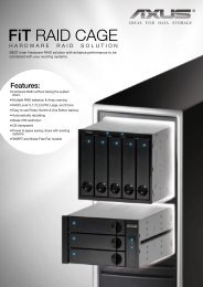
<strong>Hardware</strong> Operation ManualIIdenttiiffyiing Parttss off tthe RAIID ssyssttemThe illustrations below identify the various parts of the RAID SYSTEM. Get yourself tofamiliar with these terms as it will help you when you read further in the followingsections:Front ViewY3-24S6SF8 / Y3-24S6SS6 (<strong>Single</strong>)Y3-24S6DF8 / Y3-24S6DS6 (<strong>Redundant</strong>)15
Y3-16S6SF8 / Y3-16S6SS6 (<strong>Single</strong>)Y3-16S6DF8 / Y3-16S6DS6 (<strong>Redundant</strong>)Y3-12S6SF8 / Y3-12S6SS6 (<strong>Single</strong>)Y3-12S6DF8 / Y3-12S6DS6 (<strong>Redundant</strong>)16
<strong>Hardware</strong> Operation Manual1. LCD Display PanelThe front panel LCD continuously displays the status of the RAID SYSTEM.The following is an example of the RAID SYSTEM2. Cartridge Handle3. Lock & Release-Button4. HDD status LED IndicatorLED Colors IndicateBlue HDD On LineBlue +BlinkHDD Access? Red HDD Error5. Function keys. (ENT, ESC, Scroll up, Scroll Down)KeysUp ArrowDown Arrow(ENT ) Enter(ESC) ESCDescriptionsTo scroll upward through the menu itemsTo scroll downward through the menu itemsTo confirm a selected itemTo exit a sub-menu and return to previous menu.6.7.Power On Indicator (Blue).Power Fail / FAN Fail / Over Temperature Indicator (Red)8. A Host System Access Indicator (Blue + blink).17
18If there are SAS JBOD connected to the Raid System, PowerFail / FAN Fail / Over Temperature Indicator (Red) on LCDattached to the Raid System would only indicate events on RaidSystem itself. Power / FAN / Temperature indicators on SASJBOD Enclosure would be active if events happen on SASJBOD.
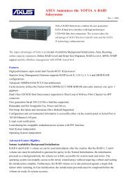
<strong>Hardware</strong> Operation ManualChassis Rear ViewY3-24S6SF8 / Y3-24S6SS6 (<strong>Single</strong>)Y3-24S6DF8 / Y3-24S6DS6 (<strong>Redundant</strong>)19
1. Controller Box 12. Controller Box 2 (Reserved for Controller 2)3. FAN failure indicator (Rear / Front)4. FAN Module 15. FAN Module 1 latch6. Power Switch7. FAN failure indicator (Rear / Front)8. FAN Module 29. FAN Module 2 latch10. AC inlet 1 & Latch11. Power Module 112. AC inlet 2 & Latch13. Power Module 214. AC inlet 3 & Latch15. Power Module 316. BBM20
<strong>Hardware</strong> Operation ManualY3-16S6SF8 / Y3-16S6SS6 (<strong>Single</strong>)Y3-16S6DF8 / Y3-16S6DS6 (<strong>Redundant</strong>)21
1. Controller Box 2 (Reserved for Controller 2)2. Controller Box 13. FAN failure indicator (Rear / Front)4. FAN Module 15. FAN Module 1 latch6. Power Switch7. FAN failure indicator (Rear / Front)8. FAN Module 29. FAN Module 2 latch10. AC inlet 1 & Latch11. Power Module 112. AC inlet 2 & Latch13. Power Module 222
<strong>Hardware</strong> Operation ManualY3-12S6SF8 / Y3-12S6SS6 (<strong>Single</strong>)Y3-12S6DF8 / Y3-12S6DS6 (<strong>Redundant</strong>)1. Power Module 12. AC inlet 13. FAN Module 14. FAN failure indicator (Rear / Front)5. Power Switch6. FAN Module 27. FAN failure indicator (Rear / Front)23
8. Power Module 29. AC inlet 210. Controller Box 111. Controller Box 2 (Reserved for Controller 2)12. BBMController Rear ViewY3-24S6SF8 / Y3-24S6DF8Y3-16S6SF8 / Y3-16S6DF824
<strong>Hardware</strong> Operation ManualY3-12S6SF8 / Y3-12S6DF81. FC CH 0 (Link & Access LED Indicator)2. FC CH 1 (Link & Access LED Indicator)3. FC CH 2 (Link & Access LED Indicator)4. FC CH 3 (Link & Access LED Indicator)LED Colors IndicateFC GreenLinkBlue + Blink Access5. Console6. Terminal7. LAN port8. Raid Controller Status LED & Fault LED IndicatorLED Colors IndicateStatus Green + Blink Raid Controller OKFault Red Raid Controller Fault9. Reserved25
10. Reserved Port LED Indicator (Link / Access)LED Colors IndicateSAS GreenLinkBlue + Blink Access11. SAS Expand 1 Port12. SAS Expand 1 LED Indicator (Link / Access)13. SAS Expand 0 Port14. SAS Expand 0 LED Indicator (Link / Access)Y3-24S6SS6 / Y3-24S6DS6Y3-16S6SS6 / Y3-16S6DS626
<strong>Hardware</strong> Operation ManualY3-12S6SS6 / Y3-12S6DS61. SAS CH02. SAS CH0 LED Indicator (Link / Access)3. SAS CH14. SAS CH1 LED Indicator (Link / Access)LED Colors IndicateSAS GreenLinkBlue + Blink Access5. Console6. Terminal7. LAN port8. Raid Controller Status LED & Fault LED IndicatorLED Colors IndicateStatus Green + Blink Raid Controller OKFault Red Raid Controller Fault9. Reserved10. Reserved Port LED Indicator (Link / Access)LED Colors IndicateSAS GreenLinkBlue + Blink Access27
11. SAS Expand 1 Port12. SAS Expand 1 LED Indicator (Link / Access)13. SAS Expand 0 Port14. SAS Expand 0 LED Indicator (Link / Access)28
<strong>Hardware</strong> Operation ManualSpace RequiirementtWhen selecting a location for your system, be sure to allow an adequate space. Thesystem has vents around it which will require a minimum of 3 inches of unobstructedspace for airflow. Openings in the equipment should be blocked, or there may be anissue of reliability problems with your system. A system product should never be placearound a radiator or heat register.Syssttem ConnecttiionConnect all cables and power cord as shown below:Cable Raid System Device PurposeRS-232 CableRS-232 CableTerminal PortConsole PortANSI Terminal or a PC withConfiguration UtilityTerminal emulator.Debug port, to check andANSI Terminal or a PC withmonitoring all of status ofTerminal emulator.RAID subsystem.Fibre cablePrimary FC-ALSecondly FC-ALFC HBA of Host computerHost interface betweenRAID and Host computerMini SAS CablePrimary SASSecondly SASHost interface betweenSAS HBA of Host computerRAID and Host computerRJ 45 Cable Ethernet Port Switch or HUB Connect to Internet.Mini SAS Cable SAS Expander Port Raid System Connect to SAS ExpanderPower Cord Power inlet A/C power outlet A/C power inputMake sure that all the devices are powered off before connecting or removingcables to prevent power spikes which can damage technical components.29
IInssttallll hard diisskssThe RAID SYSTEM includes 12/16/24 (depending on your models) removable disk cartridges. Thefollowing sections describe how to install disks into RAID SYSTEM subsystems.Remove CartridgesWe designed the lock/unlock mechanismon a same button and calledEzSecurLock. No need a key but withsecurity.How to remove Cartridges?1: Push the button inward2: While holding in the button, then slidedown3: The HDD door will be openedautomatically.Install CartridgesReversed the procedures of “Remove cartridges” to install cartridges back to RAIDsystem.30
<strong>Hardware</strong> Operation ManualInstall HDDs.1) Put HDD into the Cartridge.2) Align 4 screws holes on both HDD &Cartridge.3) Fasten all 4 screws to mount HDD inthe cartridge and make sure the HDD isproperly tightened.31
Install SATA HDDs with SAS BridgeBoard1.) Install SAS Bridge Board on to SASBridge Board Bracket and fasten it withprovided screws.2.) Install SAS Bridge Board withBracket on to Cartridge,3.) Screw SAS Bridge Board Bracketwith Cartridge,1) Insert HDD into HDD Cartridge.32
<strong>Hardware</strong> Operation Manual2) Align 4 screws holes on both HDD &Cartridge.3) Fasten all 4 screws to mount HDD inthe cartridge and make sure the HDD isproperly tightened.When using SATA HDD with <strong>Redundant</strong> Controller, it is requiredto install SAS Bridge Board. If operating with <strong>Single</strong> Controlleronly, SAS Bridge Board will not be required.33
Chapter 2<strong>Hardware</strong> InstallationThis chapter presents: IInnsst trruucct tioonnss oonn rreeppl laacci inngg ccoomppoonneennt tss IInnsst trruucct tioonnss oonn rreeppl laacci inngg thhee t hhoot t sswaappppaabbl lee ccoomppoonneennt tss IInnsst trruucct tioonnss oonn hhoow too t innsst i taal lll aanndd uuppggrraaddee DRAMRepllace tthe ConttrollllerRead the replacing notices in this chapter before proceeding withreplacement.This section provides instructions for the removal and installation of the RAIDcontroller components indicated in the figure below. This section is for the reference ofengineers. End users should not need to replace or remove components.34
<strong>Hardware</strong> Operation ManualRemoving the controller from Y3-24/16/12S6 seriesY3-24S6 <strong>Series</strong>1:1-1) Disconnect the hostcables1-2) Turn anti-clockwise torelease the thumb screw.1-3) Use the eject kit to removecontroller board.2:Slide it back and lifting offY3-16S6 <strong>Series</strong>Y3-12S6 <strong>Series</strong>Installing the controller into Y3-24/16/12S6 seriesReverse the procedures as above to install the controller into Y3-24/16/12S6 series35
Onlliine Hott Swap tthe <strong>Redundant</strong>t ConttrollllerRemoving the controller module from Y3-24/16/12S6D seriesY3-24S6D <strong>Series</strong>1:1-1) Disconnect the hostCables on Controller 11-2) Turn anti-clockwise to releasethe Controller 1 thumb screw.1-3) Use the Controller 1 eject kit toremove controller board.2:Slide it back and lifting off.Y3-16S6D <strong>Series</strong>Y3-12S6D <strong>Series</strong>NoteWhen controller 1 was removed,controller 2 will then take overcontroller 1’s job.36
<strong>Hardware</strong> Operation ManualInstalling controller module from Y3-24/16/12S6D series1:1-1) Insert Controller 1 module back to Y3 series Chassis.1-2) Use eject kit and insert Controller 1 module to the very end.2:2-1) Turn clockwise to fasten the thumb screw.2-2) Connect the host cablesThe function of the Switch on Y3 <strong>Single</strong>/<strong>Redundant</strong> Controller:1) Ensure controller is inserted and fasten at proper position to avoidany fault caused by vibration.2) Support controller hot swap.To prevent any kind of controller malfunction, it is NECESSARY to fastenthe thumb screw when install the Controller into Y3 <strong>Series</strong> Chassis.After remove Controller module, please wait 15 seconds before insertController module back into chassis. If Controller module was insertedback to quickly, which Controller may still be in fail state, and not beable to boot up.37
After insert back Controller module, the Fault LED (Red) will bedimmed, and with a Beep sound (Controller booting). This indicates thecontroller is starting to boot up.Controller 1 module will take back the job which was assign to it afterthe process of boot up.38
<strong>Hardware</strong> Operation ManualRepllaciing // Upgradiing DDR<strong>III</strong>I SDRAMRead the pre-installation notices in this chapter before proceedingwith installation.RAID SYSTEM is normally supplied with 1GB DDRII-800 SDRAM installed.There's no set formula to determine how much cache memory to use,but as a general rule, a workstation, with mostly very large files, suchas for audio or video editing and playback, graphics or CAD files, canbenefit from a large cache. File servers, with multiple random accessof varying file size, generally have little or no performanceimprovement with additional cache.Memory serves as the data buffer to increase the CPU utilization rate and minimize theoverhead of data accessing, thus, improves the overall performance.Y3-12S6/16S6/24S6 supports up to 4GB DDRII-800 DIMM type with ECC registeredtype memories.The DDR memory socket is used 240-pin DDR2 DIMM socket. Use 25 degree DDR2DIMM socketDDRII SDRAM DIMM specifications:MemoryMemory type 240-pin DDR2 DIMM x 1Memory socket type 25 degree DDR2 DIMM socketMemory size Up to 4GB with 64-bit DDRII-800 with ECC registered(using x8 or x16 chip organization)39
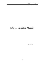
Installing memory moduleBefore install a DDRII SDRAM ensures the system is power off and disconnected.Then:1: Removing the controller module fromRaid system.2: Open the cover of controller module.3. Insert a memory module into thememory socket.4. Close the cover of controller module.Y3-12S6 <strong>Series</strong>Y3-16S6 <strong>Series</strong>Y3-24S6 <strong>Series</strong>Before starting any kind of hardware installation, please ensure thatall power switches have been turned off and all power cordsdisconnected to prevent personal injury and damage to the hardwareUse screws provided with RAID system only. Longer or shorter screwsmay cause electric shorting or un-proper installed.40
<strong>Hardware</strong> Operation ManualStatic electricity can damage electronic components. To guard againstsuch damage:Work in a static-free environmentWear a grounded anti-static wrist strapStore uninstalled components in anti-static bagsHandle PCBs by their edges and avoid touching chips and connectors.41
Hott Swappiing tto repllace tthe Fan ModulleThis section provides instructions for the removal and installation of the Fan Moduleindicated in the figure below.Y3-16S6 & Y3-24S6 <strong>Series</strong>Removing the Fan Module fromY3-16S6/Y3-24S6 <strong>Series</strong>:Remove the Fan modules by pushingthe latch to release the lock ofmodule then slide it back and liftingoff.Installing the Fan module intoY3-16S6/Y3-24S6 <strong>Series</strong>:Insert a Fan module into system, thelatch will lock the Fan moduleautomatically.42
<strong>Hardware</strong> Operation ManualY3-12S6 <strong>Series</strong>Removing the Fan Module fromY3-12S6 <strong>Series</strong>:1.) Turn anti-clockwise to release thethumb screw.2.) Use the eject kit to remove FanModule.3.) Slide it back and lifting offInstalling the Fan module intoY3-12S6 <strong>Series</strong>:Reverse the procedures as above toinstall the Fan module into Y3-12S6<strong>Series</strong>.43
Replacing Fan in a Fan Module:Step 1: Turn anti-clock wise to release the thumb screw.Step 2: slide the cover to blue arrow direction .Step 3: Remove the cover of Fan module and lift the Fans.44
<strong>Hardware</strong> Operation ManualHott Swappiing tto repllace tthe Power ModulleThis section provides instructions for the removal and installation of the PowerModule indicated in the figure below.Removing the Power Module from RAIDsystem Y3-16/24S6 <strong>Series</strong> :Removing the Power Module from RAIDsystem Y3-12S6 <strong>Series</strong> :Step 1&2: Unscrew the thumb screw.Step 3: Release the latch and hold it atunlock-position.Step 4: Slide it back and lifting off.Step 1: Unscrew the thumb screw.Step 2: Release the latch and hold it atunlock-position.Step 3: Slide it back and lifting off.Installing the Power module into RAIDsystem :Insert a Power module then fasten thescrew.The Power indicator will turn bright “Green” to indicate it haspowered on45
<strong>Hardware</strong> Operation ManualTurniing on ffor tthe ffiirsstt ttiimeWhen cabling is completed, RAID SYSTEM can be turned on. This should be done inthe following order:1. First turn on the power switch of RAID SYSTEM.2. Then power on and boot the host computer(s)When RAID SYSTEM is running, you are ready to configure one or more RAIDarrays. You have the following options:1. Turn to Chapter 2 of “Software Operation Manual” to perform a quicksetup of a single RAID array using the control panel.2. Turn to Chapter 3 of “Software Operation Manual” to access the MonitorUtility. Once the Monitor Utility is accessed, you can perform a Quick Setup(Chapter 2) or complete configuration (Chapter 4) with either the control panelor Monitor Utility.3. Turn to Chapter 4 of “Software Operation Manual” to perform a full configurationusing the control panel.Turniing offffWhen turning off RAID SYSTEM, users are advised to first shut down the server,then power off RAID SYSTEM.RessttarttiingWhen restarting RAID SYSTEM, users are advised to first restart the server,then power on RAID SYSTEM.46
<strong>Hardware</strong> Operation ManualIInsttallll tthe RAIID subsysttem iin a RackYou are shipped with one rack mounting kit for each RAID subsystem that you intend to rackmount. The RAID subsystem is designed for installation into an industry-standard 19-inch rackmount cabinet. Following the use of this section for installing the RAID subsystem into a RackStep1: Assemble and adjust the slide Railsa. Insert rear slide rail into left (right) slide railb. Adjust the length of the slide railsc. Install P4*8M Screw and M4 NUT as figure 1d. Determine where in the rack, the subsystem is going to be.Install the brackets in the rack. Secure each side of thebrackets with two position screws through the front rackposts, and two position screws through the rear rack posts.When the rails can be properly fitted to the rack posts,Fasten the screws.Figure 1: Assembly Slid rail and rack posts47
<strong>Hardware</strong> Operation ManualStep 2 : Install Clip nutsAttach M5 clip nut on each side of the front rack posts.Clip nuts use the figure 2 below to locate the clip nuts.Note:These clip nuts will be used to secure the subsystem through its front earsas will be discussed in Step 4.Figure 2: Attach the clip nuts to the rack posts48
<strong>Hardware</strong> Operation ManualStep 3 : Slide the subsystem into the server rackLift the subsystem enclosure and slide it slowly and gently along the slide rail intothe rack.Figure 3: Slide the subsystem into the server rack49
<strong>Hardware</strong> Operation ManualStep 4 : Secure the subsystem in the server rackFasten two M5 screws through the chassis ears in the front side of the chassis.The RAID subsystem should now be securely mounted into the rack.Figure 4: Secure the subsystem in the server rackInstall the RAID subsystem into the Rack Cabinet1. Lift the RAID subsystem (one person on each side of the RAID system) and approach therack with the button-back of the RAID subsystem facing the end of Slide rails.2. Slide the RAID subsystem evenly all the way into the rack cabinet.3. Using the rack mount screws, secure the top and bottom of the RAID subsystem to the rackframe.CautionThe RAID subsystem is heavy; two people are required to move the system in theprocedure.50
<strong>Hardware</strong> Operation ManualAppendix AHow tto deplloy tthe SAS JBOD wiitth Yotttta 3 SAS RaiidThere are many topologies of SAS JBOD with Yotta 3 SAS Raid.Ways to implement are as below:<strong>Single</strong> Controller Unit:One SAS Raid subsystem with one SAS JBOD24 Bay FC-SASRAID Subsystem24 BaySAS JBOD51
<strong>Hardware</strong> Operation ManualOne SAS Raid subsystem with two SAS JBODINOUTOUTOne SAS Raid subsystem with three SAS JBODINOUTOUT52
<strong>Hardware</strong> Operation ManualOne SAS Raid subsystem with four SAS JBODINOUTOUT53
<strong>Hardware</strong> Operation ManualDual <strong>Redundant</strong> Controller Unit:One SAS Raid subsystem with one SAS JBODJBOD Link AJBOD Link B24 Bay SAS-SASRAID Subsystem(Rear Side)Controller 1Controller 2SAS Expander 124 BaySAS JBODSAS Expander 2INOUTOUT54
<strong>Hardware</strong> Operation ManualOne SAS Raid subsystem with two SAS JBOD55
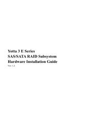
<strong>Hardware</strong> Operation ManualOne SAS Raid subsystem with three SAS JBOD24 Bay SAS-SASRAID Subsystem(Rear Side)JBOD Link AJBOD Link BController 1Controller 2IN24 BaySAS JBODOUTOUTSAS Expander 124 BaySAS JBOD24 BaySAS JBODSAS Expander 256
<strong>Hardware</strong> Operation ManualOne SAS Raid subsystem with four SAS JBOD24 Bay SAS-SASRAID Subsystem(Rear Side)JBOD Link AJBOD Link BController 1Controller 2IN24 BaySAS JBODOUTOUTSAS Expander 124 BaySAS JBOD24 BaySAS JBODSAS Expander 2SAS Expander 2SAS Expander 116 BaySAS JBOD57
<strong>Hardware</strong> Operation ManualIt supports up to four tiers and 122 SAS/SATAII peripheral devices(SAS/SATAHDDs + Raid Enclosures) by using SAS expanders. One Volume Set supports up to 32 HDDs One SAS Raid subsystem supports up to 128 Volumes One SAS Raid subsystem supports up to 122 SAS/SATAII peripheral devices(SAS/SATA HDDs + Raid Enclosures) by using SAS expanders.There are four tiers within JBOD topology as above: First tier is a RAID System. Second tier is a SAS JBOD with a SAS CH0 on it. Connecting SAS CH0 to SASexp. Port on RAID System via a Mini SAS to Mini SAS Cable. Third tier could be two SAS JBODs with a SAS CH0 port individually. One isconnected to the SAS EXP. Port on the second tier SAS JBOD via a Mini SAS toMini SAS Cable. Another is connected to the SAS CH1/E Port on the second tierSAS JBOD. Fourth tier is a SAS JBOD with a SAS CH0 on it. Connecting SAS CH0 to SASexp. Port on third tier SAS JBOD via a Mini SAS to Mini SAS Cable.It is often recommended to install the hard drive withsame brand, model no., interface and capacity in thisRAID subsystem.Due to hard drives spin at different speed and it may lead tocompatible issue or performance decline. So we do notrecommend users to install SAS and SATA hard drivemeantime in an enclosure.58
<strong>Hardware</strong> Operation ManualRAID members need to be included at the same enclosurewhich means you need to create array in the sameenclosure. If RAID members are created from two ormore different enclosures, there would be some risks(for example: if a mini-SAS cable gets problem, moreRAID members will be lost, volume sets belong to thisArray may be failed. Shutdown RAID and JBOD to fixproblem, after that, turn on JBOD and RAID systemagain and controller will get array back, but in somecase it may not get the array back)Turniing on ffor tthe ffiirsstt ttiimeWhen cabling is completed, SAS RAID system + SAS JBOD system can be turned on.This should be done in the following order:1. First turn on the power switch of “SAS JBOD” system.2. Then turn on the power switch of “SAS RAID” system3. Power on and boot the host computer(s)Turniing offffWhen turning off SAS RAID system + SAS JBOD system, users are advised to firstshut down the server, then power off SAS RAID SYSTEM ,finally power off SASJBOD SYSTEM.59
<strong>Hardware</strong> Operation ManualAppendix BConnectorsEthernet RJ-45 Connector18Pin#Signal Name1 TX+2 TX-3 RX+4 NC5 NC6 RX-7 NC8 NCRJ-11 RS-232Pin# Signal Pin# Signal1 NC 6 NC2 GND3 RX4 TX5 CTS60
<strong>Hardware</strong> Operation ManualFibre SFPPin# Signal Name1 VEFT2 TFAULT3 TDIS4 MOD_DEF(2)5 MOD_DEF(1)6 MOD_DEF(0)7 Rate Select8 LOS9 VEER10 VEER11 VEER12 RD-13 RD+14 VEER15 VCCR16 VCCT17 VEET18 TD-19 TD+20 VEET61
<strong>Hardware</strong> Operation ManualMini-SAS cable ConnectorPin# Signal Name Pin# Signal NameA1 GND B1 GNDA2 RX0+ B2 TX0+3A3 RX0- B3 TX0-A4 GND B4 GNDA5 RX1+ B5 TX1+A6 RX1- B6 TX1-A7 GND B7 GNDA8 RX2+ B8 TX2+A9 RX2- B9 TX2-A10 GND B10 GNDA11 RX3+ B11 TX3+A12 RX3- B12 TX3-A13 GND B13 GND62
<strong>Hardware</strong> Operation ManualAppendix CBattery Backup Module (BBM)The external RAID controller operates using cache memory .The battery Backup Module isan add-on module that provides power to the external RAID controller cache memory in theevent of a power failure. The Battery Backup Module monitors the write back cache on theexternal RAID controller, and provides power to the cache memory if it contains data not yetwritten to the hard drives when power failure occurs.BBM ComponentsBBM Specifications:MechanicalBattery Board Dimension (W x H x D) : 45 x 14 x 54 mmBattery pack Dimension (W x H x D) : 50 x 10 x 147 mmBattery pack Connector3 x Pins ConnectorInput Voltage+3.6 VDCOn Board Battery Capacity3000MAH (3*1000MAH)63
<strong>Hardware</strong> Operation ManualBBM Installation Procedures (Y3-16S6)Make sure all power to the system is disconnected.Use screw driver to release Controller's top cover screw and take off top cover.Install Battery Board(ARC8006-2) pin connector into Controller J7 connector,J7connector location is shown as in bellow :Install three 34mm Stand-off and Battery pack on stand-off as in bellow:64
<strong>Hardware</strong> Operation ManualInsert Battery pack 3 pin connector into Battery Board (ARC8006-2) JA2 connector,JA2 location shown as in bellow:Put back the top cover of the Controller moduleY3-12S6 & Y3-24S6 RAID system please check “BBM Installation Procedures<strong>V1</strong>.0.pdf”Battery Backup CapacityBattery backup capacity is defined as the maximum duration of a power failure for whichdata in the cache memory can be maintained by the battery. The BBM’s backup capacityvaried with the memory chips that installed on the external RAID controller..Capacity Memory Type Battery Backup duration(Hours)1GB Memory Normal 1502GB Memory Normal 100OperationBattery conditioning is automatic. There are no manual procedures for batteryconditioning or preconditioning to be performed by the user.In order to make sure of all the capacity is available for your battery cells, allow thebattery cell to be fully charged when installed for the first time. The first time charge ofa battery cell takes about 24 hours to complete.65
<strong>Hardware</strong> Operation ManualRemoving the Battery Backup ModuleThe battery module will need to be removed for one of the following reason:Disconnect battery module if there is a long storage period before deploymentThe LI-ION battery will no longer accept a charge properly.66
<strong>Hardware</strong> Operation ManualAppendix DSpecificationsY3-24S6SF8/Y3-16S6SF8/Y3-12S6SF8Model Y3-24S6SF8 Y3-16S6SF8 Y3-12S6SF8Number of RAIDcontroller1RAID CPU EngineLSI 800MHz RAID-on-Chip (ROC) processorCache Support(Write back)Up to 4GB 240pins DDR2-800 with ECC registered SDRAM Memory using x8 or x16 chiporganizationRAID Levels0, 1,10(1E), 3, 5 , 6, 30, 50 ,60 & JBODMultiple RAID selectionsOnline array roamingOffline RAID setOnline RAID level / stripe size migrationOnline capacity expansion and RAID level migration simultaneouslyOnline volume set growthSupport global and local hot spareRAID Features Instant availability and background initializationAutomatic drive insertion / removal detection and rebuilding.Greater than 2TB per volume set ( 64-bit LBA support ), Greater than 2TB per disk driveDisk scrubbing / array verify scheduling for automatic repair of all configured RAID setsLogin record in the event log with IP address and service (http, telnet and serial)Support NTP protocol to synchronize RAID controller clock over the on-board LAN portMax 122 devicesMax 128 LUNs (Volume set )System Type2U / 3U / 4U Rack-MountHost InterfaceQuad FC 8Gb portDisk InterfaceSAS 6Gb / SATA 6GbDisk Channel 24 Bay Disk Channel 16 Bay Disk Channel 12 Bay Disk ChannelJBOD Expansion Port Dual Mini SAS JBOD Expansion Port can be attached to SAS JBOD to expand capacityBattery BackupModulesupporting 72 hours battery backup time(Optional)Hot SwapComponentsPower Supply, FAN, Disk Drive,Firmware embedded Web browser-based RAIDmanager via built-in 10/100 Ethernet portRAID Management Firmware embedded manager via RS-232 portFirmware embedded manager through LCD control panelField-upgradeable firmware from flash ROMMonitors &NotificationsOperating SystemsPower SupplyElectricalTemperatureRelative HumidityDimensionsAll system status can be monitored via Firmware-embedded Web browser-based RAID managerSystem status indication through LCD, LED and alarm buzzerAll system events can be sent to multiple user via emails alertsSNMP agent already embedded in the firmware allows remote to monitor events through LANO/S Independent and Transparent24 bays systems: <strong>Redundant</strong> bythree 460W power modules withPFC feature, loading sharing typeand cable-less design16 bays systems: <strong>Redundant</strong> bydual 460W power modules withPFC feature, loading sharing typeand cable-less design12 bays systems: <strong>Redundant</strong> bydual 400W power modules withPFC feature, loading sharing typeand cable-less designAC Voltage 110-230 VACAc Frequency 50-60HzOperating Temperature : 5 to 35 degree C.Non Operating Temperature : -40 to 60 degree C.20% to 80% non-condensing446.6mm(W)*560mm(D)*4U(H) 446.6mm(W)*560mm(D)*3U(H) 446.6mm(W)*560mm(D)*2U(H)67
<strong>Hardware</strong> Operation ManualY3-24S6DF8/Y3-16S6DF8/Y3-12S6DF8Model Y3-24S6DF8 Y3-16S6DF8 Y3-12S6DF8Number of RAIDcontroller2RAID CPU EngineLSI 800MHz RAID-on-Chip (ROC) processorCache Support(Write back)Up to 4GB 240pins DDR2-800 with ECC registered SDRAM Memory using x8 or x16 chiporganizationRAID Levels0, 1,10(1E), 3, 5 , 6, 30, 50 ,60 & JBODALUA (Asymmetric Logic unit Access) Compliant ArrayMPIO / Failover/Failback SupportedMultiple RAID selectionsOnline array roamingOffline RAID setOnline RAID level / stripe size migrationOnline capacity expansion and RAID level migration simultaneouslyOnline volume set growthRAID Features Support global and local hot spareInstant availability and background initializationAutomatic drive insertion / removal detection and rebuilding.Greater than 2TB per volume set ( 64-bit LBA support ), Greater than 2TB per disk driveDisk scrubbing / array verify scheduling for automatic repair of all configured RAID setsLogin record in the event log with IP address and service (http, telnet and serial)Support NTP protocol to synchronize RAID controller clock over the on-board LAN portMax 122 devicesMax 128 LUNs (Volume set )System Type2U / 3U / 4U Rack-MountHost InterfaceQuad FC 8Gb port /per controllerDisk InterfaceSAS 6Gb / SATA 6Gb with SAS Bridge Board (optional)Disk Channel 24 Bay Disk Channel 16 Bay Disk Channel 12 Bay Disk ChannelJBOD Expansion Port Dual Mini SAS JBOD Expansion Port can be attached to SAS JBOD to expand capacity /per controllerBattery BackupModulesupporting 72 hours battery backup time(Optional)Hot SwapComponentsRAID ManagementMonitors &NotificationsOperating SystemsPower SupplyElectricalTemperatureRelative HumidityDimensionsController, Power Supply, FAN, Disk Drive,Firmware embedded Web browser-based RAIDmanager via built-in 10/100 Ethernet portFirmware embedded manager via RS-232 portFirmware embedded manager through LCD control panelField-upgradeable firmware from flash ROMAll system status can be monitored via Firmware-embedded Web browser-based RAID managerSystem status indication through LCD, LED and alarm buzzerAll system events can be sent to multiple user via emails alertsSNMP agent already embedded in the firmware allows remote to monitor events through LANO/S Independent and Transparent24 bays systems: <strong>Redundant</strong> bythree 460W power modules withPFC feature, loading sharing typeand cable-less design16 bays systems: <strong>Redundant</strong> bydual 460W power modules withPFC feature, loading sharing typeand cable-less design12 bays systems: <strong>Redundant</strong> bydual 400W power modules withPFC feature, loading sharing typeand cable-less designAC Voltage 110-230 VACAc Frequency 50-60HzOperating Temperature : 5 to 35 degree C.Non Operating Temperature : -40 to 60 degree C.20% to 80% non-condensing446.6mm(W)*560mm(D)*4U(H) 446.6mm(W)*560mm(D)*3U(H) 446.6mm(W)*560mm(D)*2U(H)68
<strong>Hardware</strong> Operation ManualY3-24S6SS6/Y3-16S6SS6/Y3-12S6SS6Model Y3-24S6SS6 Y3-16S6SS6 Y3-12S6SS6Number of RAIDcontroller1RAID CPU EngineLSI 800MHz RAID-on-Chip (ROC) processorCache Support(Write back)Up to 4GB 240pins DDR2-800 with ECC registered SDRAM Memory using x8 or x16 chiporganizationRAID Levels0, 1,10(1E), 3, 5 , 6, 30, 50 ,60 & JBODMultiple RAID selectionsOnline array roamingOffline RAID setOnline RAID level / stripe size migrationOnline capacity expansion and RAID level migration simultaneouslyOnline volume set growthSupport global and local hot spareRAID Features Instant availability and background initializationAutomatic drive insertion / removal detection and rebuilding.Greater than 2TB per volume set ( 64-bit LBA support ), Greater than 2TB per disk driveDisk scrubbing / array verify scheduling for automatic repair of all configured RAID setsLogin record in the event log with IP address and service (http, telnet and serial)Support NTP protocol to synchronize RAID controller clock over the on-board LAN portMax 122 devicesMax 128 LUNs (Volume set )System Type 4U Rack-Mount 3U Rack-Mount 2U Rack-MountHost InterfaceDual Mini SAS ports(8088)Disk InterfaceSAS 6Gb / SATA 6GbDisk Channel 24 Bay Disk Channel 16 Bay Disk Channel 12 Bay Disk ChannelJBOD Expansion Port Dual Mini SAS JBOD Expansion Port can be attached to SAS JBOD to expand capacityBattery BackupModulesupporting 72 hours battery backup time(Optional)Hot SwapComponentsPower Supply, FAN, Disk Drive,Firmware embedded Web browser-based RAIDmanager via built-in 10/100 Ethernet portRAID Management Firmware embedded manager via RS-232 portFirmware embedded manager through LCD control panelMonitors &NotificationsOperating SystemsPower SupplyElectricalTemperatureRelative HumidityDimensionsField-upgradeable firmware from flash ROMAll system status can be monitored via Firmware-embedded Web browser-based RAID managerSystem status indication through LCD, LED and alarm buzzerAll system events can be sent to multiple user via emails alertsSNMP agent already embedded in the firmware allows remote to monitor events through LAN24 bays systems: <strong>Redundant</strong> bythree 460W power modules withPFC feature, loading sharing typeand cable-less designO/S Independent and Transparent16 bays systems: <strong>Redundant</strong> bydual 460W power modules withPFC feature, loading sharing typeand cable-less design12 bays systems: <strong>Redundant</strong> bydual 400W power modules withPFC feature, loading sharing typeand cable-less designAC Voltage 110-230 VACAc Frequency 50-60HzOperating Temperature: 5 to 35 degree C.Non Operating Temperature: -40 to 60 degree C.20% to 80% non-condensing446.6mm(W)*560mm(D)*4U(H) 446.6mm(W)*560mm(D)*3U(H) 446.6mm(W)*560mm(D)*2U(H)69
<strong>Hardware</strong> Operation ManualY3-24S6DS6/Y3-16S6DS6/Y3-12S6DS6Model Y3-24S6DS6 Y3-16S6DS6 Y3-12S6DS6Number of RAIDcontroller2RAID CPU EngineLSI 800MHz RAID-on-Chip (ROC) processorCache Support(Write back)Up to 4GB 240pins DDR2-800 with ECC registered SDRAM Memory using x8 or x16 chiporganizationRAID Levels0, 1,10(1E), 3, 5 , 6, 30, 50 ,60 & JBODALUA (Asymmetric Logic unit Access) Compliant ArrayMPIO / Failover/Failback SupportedMultiple RAID selectionsOnline array roamingOffline RAID setOnline RAID level / stripe size migrationOnline capacity expansion and RAID level migration simultaneouslyOnline volume set growthRAID Features Support global and local hot spareInstant availability and background initializationAutomatic drive insertion / removal detection and rebuilding.Greater than 2TB per volume set ( 64-bit LBA support ), Greater than 2TB per disk driveDisk scrubbing / array verify scheduling for automatic repair of all configured RAID setsLogin record in the event log with IP address and service (http, telnet and serial)Support NTP protocol to synchronize RAID controller clock over the on-board LAN portMax 122 devicesMax 128 LUNs (Volume set )System Type 4U Rack-Mount 3U Rack-Mount 2U Rack-MountHost InterfaceDual Mini SAS ports(8088) /per controllerDisk InterfaceSAS 6Gb / SATA 6Gb with SAS Bridge Board (optional)Disk Channel 24 Bay Disk Channel 16 Bay Disk Channel 12 Bay Disk ChannelJBOD Expansion Port Dual Mini SAS JBOD Expansion Port can be attached to SAS JBOD to expand capacity /per controllerBattery BackupModulesupporting 72 hours battery backup time(Optional)Hot SwapComponentsController, Power Supply, FAN, Disk Drive,Firmware embedded Web browser-based RAIDmanager via built-in 10/100 Ethernet portRAID Management Firmware embedded manager via RS-232 portFirmware embedded manager through LCD control panelField-upgradeable firmware from flash ROMMonitors &NotificationsOperating SystemsPower SupplyElectricalTemperatureRelative HumidityDimensionsAll system status can be monitored via Firmware-embedded Web browser-based RAID managerSystem status indication through LCD, LED and alarm buzzerAll system events can be sent to multiple user via emails alertsSNMP agent already embedded in the firmware allows remote to monitor events through LAN24 bays systems: <strong>Redundant</strong> bythree 460W power modules withPFC feature, loading sharing typeand cable-less designO/S Independent and Transparent16 bays systems: <strong>Redundant</strong> bydual 460W power modules withPFC feature, loading sharing typeand cable-less design12 bays systems: <strong>Redundant</strong> bydual 400W power modules withPFC feature, loading sharing typeand cable-less designAC Voltage 110-230 VACAc Frequency 50-60HzOperating Temperature: 5 to 35 degree C.Non Operating Temperature: -40 to 60 degree C.20% to 80% non-condensing446.6mm(W)*560mm(D)*4U(H) 446.6mm(W)*560mm(D)*3U(H) 446.6mm(W)*560mm(D)*2U(H)70
<strong>Hardware</strong> Operation Manual*Specification subject to change without notice, all trademarks orregistered trademarks are properties of their respective owners.71