Gledhill High Efficiency Condensing Boiler - Gledhill Spare Parts
Gledhill High Efficiency Condensing Boiler - Gledhill Spare Parts
Gledhill High Efficiency Condensing Boiler - Gledhill Spare Parts
- No tags were found...

Create successful ePaper yourself
Turn your PDF publications into a flip-book with our unique Google optimized e-Paper software.
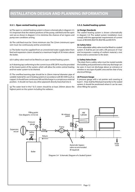
INSTALLATION DESIGN AND PLANNING INFORMATION3.5.1. Open vented heating system(a) The open i.e. vented heating system is shown schematically in diagram 3.3.It is important that the relative positions of the pump, cold feed and the openvent are as shown in diagram 3.3 to minimise the chances of air ingress andpump over conditions arising.(b) The cold feed must be 15mm minimum size. The 22mm (minimum) openvent must rise continuously and be unrestricted.(c) The boiler must be supplied from an unrestricted water supply taken fromfeed and expansion cistern situated at a maximum height of 30 meters abovethe boiler.(d) A safety valve need not be fitted to an open vented heating system.(e) A draining tap conforming to the current issue of BS 2879, must be providedat the lowest point of the system, which will allow the entire central heatingand hot water system to be drained.(f ) The overflow/warning pipe should be in 20mm internal diameter pipe ofsuitable material for use in heating systems in accordance with BS 5449 (such ascopper). It should have continuous fall and discharge in a conspicuous externalposition. It should not have any other pipework directly branched into it.(g) The water level in the F & E cistern should be at least 250mm above thehighest point on the system including the radiators3.5.2. Sealed heating system(a) Design StandardsThe sealed heating system is shown schematicallyin diagram 3.4. The sealed system installation mustcomply with the appropriate requirements of currentissues of BS5449, BS6759, BS6798 and BS7074.(b) Safety ValveA non-adjustable safety valve must be fitted to a sealedsystem. It shall be pre-set with a lift pressure of 3 barand incorporate a seating of resilient material, a testdevice and a connection to the drain(c) Safety Valve DrainThe drain from a safety valve must be routed outsidethe building and positioned so that any discharge canbe seen. It must not discharge above an entrance orwindow or any type of public area and be clear of anyelectrical fittings.(d) Pressure GaugeA pressure gauge with a set pointer and covering atleast 0 – 4 bar shall be fitted permanently to the sealedsystem. It should be positioned where it can be seenwhen filling the system. Page 12