8pp GHP BROCHURE - Mitsubishi Heavy Industries Ltd.
8pp GHP BROCHURE - Mitsubishi Heavy Industries Ltd.
8pp GHP BROCHURE - Mitsubishi Heavy Industries Ltd.
- No tags were found...

Create successful ePaper yourself
Turn your PDF publications into a flip-book with our unique Google optimized e-Paper software.
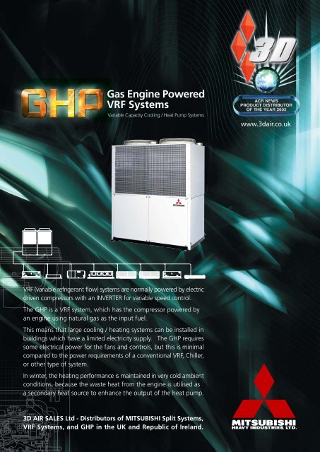
Gas Engine PoweredVRF SystemsVariable Capacity Cooling / Heat Pump Systemswww.3dair.co.ukVRF (variable refrigerant flow) systems are normally powered by electricdriven compressors with an INVERTER for variable speed control.The <strong>GHP</strong> is a VRF system, which has the compressor powered byan engine using natural gas as the input fuel.This means that large cooling / heating systems can be installed inbuildings which have a limited electricity supply. The <strong>GHP</strong> requiressome electrical power for the fans and controls, but this is minimalcompared to the power requirements of a conventional VRF, Chiller,or other type of system.In winter, the heating performance is maintained in very cold ambientconditions, because the waste heat from the engine is utilised asa secondary heat source to enhance the output of the heat pump.3D AIR SALES <strong>Ltd</strong> - Distributors of MITSUBISHI Split Systems,VRF Systems, and <strong>GHP</strong> in the UK and Republic of Ireland.
The application of air conditioning systems powered by internal combustion engineshas been in existence for over twenty years in the UK. All of these applicationshave been mainly experimental, and are bespoke designs. This has resulted in highequipment costs, which have prohibited future commercial viability.The very attractive concept developed by <strong>Mitsubishi</strong> provides many benefits forthe designer, the installer, and reduces running costs for the client. VRF systemsare extensively applied to commercial buildings - approximately 7800 systemsper year are installed in the UK. The technology is well known, and specialistinstallers are familiar with the installation requirements and the procedures forcommissioning. All of these VRF systems are powered by electricity, usually a 3-phase power supply. The compressor normally would use 96% of the electricalpower of the outdoor unit, the remaining 4% being for the fans and control system.The <strong>GHP</strong> is a VRF - Variable Refrigerant Flow - system, which behaves in a similaroperational mode to conventional electric powered VRF systems. Instead of usingelectrical power for the compressor, the <strong>GHP</strong> compressor is driven by an engine,very similar to a car engine, having four cylinders, spark plugs, etc, and capableof being controlled at varying speeds, i.e. similar to the INVERTER on an electricsystem. The engine is directly coupled to a <strong>Mitsubishi</strong> compressor.VRF Cooling / Heat PuTechnical Features & Benefits of <strong>GHP</strong>• Low carbon emissions• Factory commissioned outdoor unit• Indoor units and control systemsidentical to conventional <strong>Mitsubishi</strong>VRF systems• Connection of up to 20 indoor units• Pipework identical to VRF systems• BEMS compatible: Trend, Satchwell...Performance - Cooling & Heating• High efficiency cooling, up to 56KW• Fast warm up, and enhanced*performance heating, up to 67KW• Continuous performance - Defrostcycle is eliminated• Heating performance is maintainedin ambient temperature to -15ºC*The heat pump performance is enhanced byutilising the waste heat from the engine. Theengine coolant is circulated through a heatexchanger to transfer waste heat energy intothe refrigerant, thus increasing the Coefficientof Performance of the heat pump operation.Because there is a constant source of heatenergy from the engine, the normal de-frostfunction of conventional systems is eliminated,so there is no shut-down period for defrosting.This also reduces warm up time from a cold start.The <strong>GHP</strong> operates in the same way as a VRF 2-pipe System, i.e. all on cooling, or all on heating.<strong>GHP</strong> - faster warm up time thanElectric Heat Pumps<strong>GHP</strong>EHP<strong>GHP</strong> - Downtime due to defrostperiods eliminated<strong>GHP</strong>EHP
16,000 <strong>Mitsubishi</strong> <strong>GHP</strong> Systems Installed in Japan<strong>Mitsubishi</strong> <strong>Heavy</strong> <strong>Industries</strong> has had many years of experience in manufacturing<strong>GHP</strong> systems for the Japanese market, where electricity costs are high, and thereare severe restrictions at peak load periods in February (heating season), andJuly (cooling season).<strong>GHP</strong> systems are installed mainly in commercial buildings, and it is quite commonto see multiple installations in office buildings and large retail stores.<strong>Mitsubishi</strong> has now developed the Mk4 <strong>GHP</strong> which is CE marked, and has theservice interval extended to 8,000 hours of operation. That equates to 2-yearsbased on 60 hours per week.The construction of the <strong>GHP</strong> consists of large heat exchangers and fans in the topsection, with a sealed engine/compressor housing below. This housing has acousticinsulation to minimise noise break out.The engine is a conventional four stroke internal combustion engine, very similarto a car engine. It has an automatic throttling device which provides speedcontrol, dependent on the combined demand of the connected indoor units.The microcomputer controlled system behaves similarly to an INVERTER systemon electric VRF units.mp SystemsThe powerful heating output of <strong>GHP</strong> is maintainedat 100% even at ambient temperatures of -15ºC.Electric Heat pumps (VRF) heating is reduced at lowambient temperatures.1.0<strong>GHP</strong>EHP-20º -15º -10º -5º 0 5º 10º 15º 20º ºCThe air intake for the engine is at the top of the unit, and passes downwardthrough the centre of the unit to the engine air filter and inlet manifold. Theexhaust gases are discharged upwards, and out of the top of the <strong>GHP</strong>. A smalldrain outlet is required for the condensate forming in the exhaust. The drain wateris passed though a ‘scrubber’ before exiting the unit.A large reservoir of oil is included to allow for prolonged operation withouttopping up.The ‘fuzzy-logic’ control which combines all the data from the indoor units andoutdoor unit constantly monitors the performance of the engine and the refrigerationsystem, in order to maximise performance, efficiency and internal comfort levels.The outdoor unit has a 7-segment 6-digit display for ease of component andsystem monitoring, and for fault diagnosis. A comprehensive explanation of theoperational and control features can be downloaded from the 3D website.
Because the compressor is powered by the engine, the <strong>GHP</strong> uses less than 1KW ofelectricity to power the fans and control equipment. The power supply is 3-ph + N.Application - Power supplies to commercial buildings are very often inadequate.Electrically powered systems, e.g. VRF, chillers, etc require a substantial power supply,which is not available in, or near, the building. The cost of installing new powersupplies can vary from £1,000 to £100,000.<strong>GHP</strong> uses approximately 10% of the power of a conventional electric VRF system.Where the supply in a building is limited, the available power can be made availablefor the building user, for lighting, lifts, IT, and office equipment.Part ‘L’ Building Regulations - The application of <strong>GHP</strong> to new or refurbishedbuildings can provide some margin in the selection of cooling/heating equipmentwithin the parameters of Part L. In particular, the <strong>GHP</strong> carbon emissions for heatingoperation, are 30% less than the emissions of a Condensing Boiler.Electrical Requirements<strong>GHP</strong> - Large Volumes in Japan - Thereis a very high peak demand on the powersupply grid in Japan in February (heatingseason) and in July (cooling season). <strong>GHP</strong>helps to reduce the demand on the gridby utilising gas as the primary energysource. <strong>GHP</strong> systems are used extensivelyfor commercial buildings in Japan,• office buildings,• retail stores,• car showrooms,• schools and universities,• hospitals• sports centresUK - First Installation - The very firstinstallation of <strong>GHP</strong> in the UK is for a clientwith a large computer room which is beingexpanded. The existing air conditioningplant is being removed, as the power isrequired for the new IT suite. The completeIT area is being cooled by <strong>GHP</strong>, providing56KW of cooling, and using only 0.9KWof electrical power.Design & Installation - The design ofthe layout of indoor units, internalrefrigerant piping, branch joints, etc, isalmost identical to a conventional VRF2-pipe system. It is important that pipesizes are correct, and that height andlength limitations are not exceeded.Over 40,000 <strong>GHP</strong> systems were installed in 2002Maximum piping length from outdoor unit to the furthest indoor unit 100mMaximum piping length from outdoor unit to first branch joint 70mMax height difference (outdoor unit above)50mMax height difference (outdoor unit below)40mDifference in height between indoor units on same system15mFor assistance with design and selection of equipment contact the 3D Sales Office.
600 or more350or more1000 or more50or more50or more50or more350or more50or more50or more1000or more2000 or more600 or more50 or more350or more1000 or moreFactory Tested & Commissioned -Each <strong>GHP</strong> outdoor unit is fully testedand commissioned at the Nagoya factoryin Japan.This means the installer’s responsibilitiesare simplified, requiring only to locatethe unit and make the necessaryconnections:• Natural gas supply• Electrical Mains Power 3ph + N• 2-wire low voltage control cableto indoor units• Refrigerant pipes - 2 pipesIt is essential the refrigerant piping isinstalled by a competent and trainedengineer possessing a Certificate forRefrigerant Safe Handling. Stringentprecautions must be taken to prevent theingress of moisture and contaminants.Nitrogen purge must be used for allbrazed pipe joints to eliminate theformation of oxides on the internalsurfaces.The gas supply must be installed by aCORGI/ACS registered installer.<strong>GHP</strong> Outdoor Unit Location - The <strong>GHP</strong> is normally installed in an openenvironment. It is essential that there is no impedance to the movement of aircirculating through the fans/heat exchangers, or to the intake and exhaust. The<strong>GHP</strong> can be installed in a perimeter enclosure, but adequate air movement mustbe provided. The <strong>GHP</strong> is fully weatherproof. Recommended space for serviceaccess and air movement is shown in the above diagram.Full details of installation requirements can be found on the 3D website -www.3dair.co.uk, or in the <strong>Mitsubishi</strong> Engineering Manual <strong>GHP</strong> 2002.3D Applications and Design - Technical Support - The control wiring andmethod of addressing the indoor units is straightforward, but needs to be properlyplanned at the design stage. The 2-wire communications connection is connectedto the AB terminals of all the indoor units on each <strong>GHP</strong> system, and then to theoutdoor unit. This method of control wiring minimises costs, and provides theuser with a very sophisticated microcomputer control scheme.3D has a team of experienced applications and support engineers who can assistwith the design and selection of equipment , and advise on refrigeration pipeconnections , control schemes and control wiring. For specific projects we canproduce schematic diagrams of unit locations, routing of sizing of refrigerantpipework, address numbering, etc.BMS and PC Based Control Schemes - 3D can provide a stand alone PC WindowsCentralised Control, which can be upgraded to allow the building user to monitorthe entire system, and to bill the occupants for the usage.The 3D Gateway and Interface connections can enable full BMS monitoring andcontrol. It is compatible with all the major BMS System providers:• TREND • SATCHWELL• HONEYWELL • STAEFA• ANDOVER • JOHNSON• CYLON • SIEMENS• ECHELON • BACNET• MODBUS
Carbon Emissions - The table (right)compares the carbon emissions of<strong>GHP</strong> 560 with a Condensing Boiler(80% efficiency) and a conventionalVRF outdoor unit (electric powered).The Carbon Intensity is the amount ofCarbon emitted per KW hour of usefulheating or cooling output.The <strong>GHP</strong> comparisons on heating arerated at ISO standard conditions, and atlower ambient conditions, which illustratethe advantages of recovering the wasteheat from the engine coolant system.Running Costs - comparisons are basedon the cost per KWh of cooling andheating output.The electricity and gas tariffs are statedbelow, and are representative ofcommercial supply contracts. VRF(Electric powered systems) are basedon COP of 2.9 (rated at 7ºC ambient)and EER of 2.7. The COP/EER at lowerambient conditions are typical of VRF,and are adjusted to take account of thereduced performance at lower ambientconditions and the reduction of usefulheat output due to defrost periods. Thepower consumption figures are basedon heating performance of 67.0KW,cooling 53.0KW. The calculations donot take into account the indoor units.Gas commercial tariff = 1.55penceper KWh (incl 0.15p CCL),Electricity commercial tariff = 5.40pence/KWh (incl. 0.43p CCL).The example is based on the <strong>GHP</strong>560rated at 67.0KW heating, 56.0KWcooling.Carbon EmissionsCarbon Intensity KgC/KWh Ambient Temp 35ºC 7ºC 0ºC -7ºC -15ºCCooling Operation VRF Electric powered 0.043<strong>GHP</strong> 0.053Heating Operation VRF Electric powered 0.042 0.051 0.049 0.059<strong>GHP</strong> 0.043 0.043 0.044 0.046Condensing Boiler 80% efficiency 0.066 0.066 0.066 0.066Running Costs (Cost: pence/KWh of cooling and heating output)Ambient 35ºC 7ºC 0ºC -7ºC -15ºCCooling VRF Electric EER 0.043Power Input KW 20.38Cost p/KWh Output 2.00<strong>GHP</strong> Gas Fuel Input KW 0.053Electricity Input KWCost p/KWh Output 1.67Heating VRF Electric COP 2.90 2.22 2.28 1.91Power Input KW 23.10 30.12 29.33 35.06Cost p/KWh Output 1.86 2.43 2.36 2.83<strong>GHP</strong> Gas Fuel Input KW 51.9 51.9 52.9 55.9Electricity Input KW 1.18 1.18 1.18 1.18Cost p/KWh Output 1.30 1.30 1.32 1.32Heating - Condensing Boiler Cost p/KWh 1.94 1.94 1.94 1.9480% efficiency<strong>GHP</strong> SpecificationModel Ref: GHCP450HMTE4 GHCP560HMTE4Cooling Performance KW 45.0 56.0Heating Performance KW 53.0 67.0Dimensions H x W x D mm 2135 x 1750 x 950 2135 x 1750 x 950Weight Net Kg 910 920Power Supply 415V 3 ph 50HZ 415V 3 ph 50HZRunning current Cooling A 2.6 2.6Heating A 1.9 1.9Power consumption Cooling KW 1.62 1.62Heating KW 1.18 1.18Start current A 19 19Gas FuelNatural gasGas Fuel consumption Cooling KW 44.3 54.6Heating KW 41.5 51.9Engine type 4 cylinder, 4 cycle, water cooled, OHVEngine size cc 2237Engine speed range rpm 890 to 2375Engine starterAC/DC variable type DC statorRefrigerant pipe connections o.d. 5/8" flare 3/4" flareo.d. 1 3/8" brazed 1 1/2" brazedRefrigerant R407C Kg 17.5 18.0Gas mains supply connection mm 25 25Drain for exhaust condensate mm Flexible hose o.d. 18.2 i.d. 12.2Compressor - open type CR5445HVR CR5453HVRCompression volume cc 454 528Condenser Fans Propellor fan x 2Fan motor type3-phase inductance motor 6-poleFan motor power KW 0.25 x 2 0.45 x 2Connectable indoor units 1 to 20Connectable capacity 22.5KW to 58.5KW 28.0KW to 72.8KWTechnical Specification
Indoor UnitsThe internal units used on <strong>GHP</strong> systems are identical to those used on KX/KXRVRF systems. The control language is the same, and all remote/centralized controlsare also the same.A total of 20 indoor units can be connected to each <strong>GHP</strong>, and can be controlledindividually, in heating or cooling mode, dependent on the mode operation ofthe <strong>GHP</strong> system, i.e. it is not possible to have some units on cooling while othersare on heating. The internal units are connected by two refrigerant pipes withbranch pipe kits or headers branching from the main 2-pipe circuit.FDT 4-Way Cassette 2.8KW to 16.0KWIntegral Condensate Lift PumpFDTQ Cassette – Single Discharge 2.2KW to 4.0KWIntegral Condensate Lift PumpFDQM Compact Ducted 2.2KW to 4.0KWIntegral Condensate Lift PumpFDTS Cassette – Single Discharge 4.5KW to 8.0KWIntegral Condensate Lift PumpFDUM Ducted Horizonta 4.5KW to 16.0KWIntegral Condensate Lift PumpFDR Ducted Cassette 4.5KW to 16.0KWIntegral Condensate Lift PumpFDK Wall Mounted 2.2KW to 8.0KWOptional Condensate Lift PumpFDFL Floor Mounted 2.8KW to 8.0KWFDFU Concealed Floor Unit 2.8KW to 8.0KWFDE Ceiling Mounted 3.6KW to 16KWFDTW 2-Way Cassette 2.8KW to 16KWIntegral Condensate Lift Pump
<strong>Mitsubishi</strong> <strong>Heavy</strong> <strong>Industries</strong> is at the forefront of <strong>GHP</strong> development and engineeringdesign, having a history in refrigeration and air conditioning dating back to 1920,as well as extensive involvement with the automotive industry and other associatedtechnologies. Over 16,000 <strong>GHP</strong> systems have been manufactured by <strong>Mitsubishi</strong>,most of which are installed in commercial buildings in Japan.3D AIR SALES <strong>Ltd</strong> distributes MITSUBISHI air conditioning and heat pump systemsin the UK and Ireland, and can offer assistance with the design and applicationof <strong>GHP</strong> and other air conditioning products manufactured in Japan by MITSUBISHIHEAVY INDUSTRIES.Technical information on all <strong>Mitsubishi</strong> <strong>Heavy</strong> <strong>Industries</strong> air conditioningproducts can be found on the 3D website at: www.3dair.co.uk3D Air Sales <strong>Ltd</strong>Sales & Marketing850 Brighton Road, Purley,Surrey CR8 2BHTel: 020 8668 1112Fax: 020 8668 1113Email: sales@3dair.co.uk3D Air Sales <strong>Ltd</strong>Sales & Accounts Administration,Spare Parts Sales, Warehouse,Technical Troubleshooting, WarrantyAnglia House, Priors Way, Coggeshall,Essex CO6 1TLTel: 01376 565 505Fax: 01376 565 5253D Air Sales <strong>Ltd</strong> ScotlandMcGregor House,South Bank BusinessPark, Kirkintilloch, Glasgow G66 1XFTel: 0141 777 5007Fax: 0141 777 5009Email: scotland@3dair.co.uk3D Air Sales Ireland <strong>Ltd</strong>Unit 8, Greenhills Business Centre,Greenhills Industrial Estate,Tallaght, Dublin 24Tel: 00 353 (0) 1462 7570Fax: 00 353 (0) 1462 7611Email: micclan1@eircom.netThe information provided in this brochure is for guidance only. It does not form any part of acontract. The manufacturer reserves the right to change specification without notice.