Lab Experiment No. 5: Single-Phase Motors
Lab Experiment No. 5: Single-Phase Motors
Lab Experiment No. 5: Single-Phase Motors
- No tags were found...

Create successful ePaper yourself
Turn your PDF publications into a flip-book with our unique Google optimized e-Paper software.
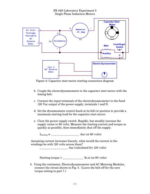
-EE 448 <strong>Lab</strong>oratory <strong>Experiment</strong> 5<strong>Single</strong> <strong>Phase</strong> Induction <strong>Motors</strong>Capacitor StartMotor60 VoltVoltageVariableACSource88214N4V1+-+Voltmeter+ Ammeter -+ -25 AmpI1Main1 2CentrifugalSwitch6 7Auxilary3 4C5120 VAC Source88211N1Electro-Dynamometer--Figure 4: Capacitor start motor starting connection diagramb. Couple the electrodynamometer to the capacitor start motor with thetiming belt.c. Connect the input terminals of the electrodynamometer to the fixed120 Vac output of the power supply, terminals 1 and N.d. Set the dynamometer control knob at its full cw position to provide amaximum starting load for the capacitor start motor.e. Close the power supply switch. Rapidly, but steadily increase thesupply variac to 60 volts. Measure the starting current and torque asquickly as possible, then immediately shut off the supply.I starting = _______________ Aac (at 60 volts)Assuming current increases linearly, what would the current in thewindings be with 120 volts across them?_______________ Aac (calculated for 120 volts)Starting torque = ___________ lb.in (at 60 volts)5. Using the wattmeter, Electrodynamometer and AC Metering Modules,connect the circuit shown in Fig. 5. (Leave the belt off for the zerotorque setting in part 7.)- 11 -