Lab Experiment No. 5: Single-Phase Motors
Lab Experiment No. 5: Single-Phase Motors
Lab Experiment No. 5: Single-Phase Motors
- No tags were found...

Create successful ePaper yourself
Turn your PDF publications into a flip-book with our unique Google optimized e-Paper software.
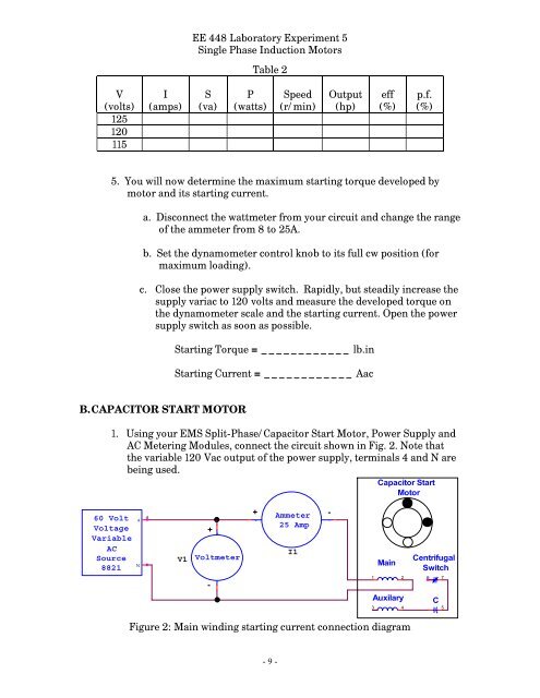
-EE 448 <strong>Lab</strong>oratory <strong>Experiment</strong> 5<strong>Single</strong> <strong>Phase</strong> Induction <strong>Motors</strong>Table 2V(volts)125120115I(amps)S(va)P(watts)Speed(r/min)Output(hp)eff(%)p.f.(%)5. You will now determine the maximum starting torque developed bymotor and its starting current.a. Disconnect the wattmeter from your circuit and change the rangeof the ammeter from 8 to 25A.b. Set the dynamometer control knob to its full cw position (formaximum loading).c. Close the power supply switch. Rapidly, but steadily increase thesupply variac to 120 volts and measure the developed torque onthe dynamometer scale and the starting current. Open the powersupply switch as soon as possible.Starting Torque = ____________ lb.inStarting Current = ____________ AacB. CAPACITOR START MOTOR1. Using your EMS Split-<strong>Phase</strong>/Capacitor Start Motor, Power Supply andAC Metering Modules, connect the circuit shown in Fig. 2. <strong>No</strong>te thatthe variable 120 Vac output of the power supply, terminals 4 and N arebeing used.Capacitor StartMotor60 VoltVoltageVariableACSource88214N4V1++Voltmeter+ Ammeter25 Amp+ -I1-MainCentrifugalSwitch-1 26 7Auxilary3 4C5Figure 2: Main winding starting current connection diagram- 9 -