BROCADE IP PRIMER
BROCADE IP PRIMER
BROCADE IP PRIMER
- No tags were found...

You also want an ePaper? Increase the reach of your titles
YUMPU automatically turns print PDFs into web optimized ePapers that Google loves.
<strong>BROCADE</strong><strong>IP</strong><strong>PRIMER</strong>FIRST EDITIONEverything you need to obtain a solidfoundation in networking technologiesand design conceptsJON FULLMER
<strong>BROCADE</strong><strong>IP</strong><strong>PRIMER</strong>FIRST EDITIONEverything you need to obtain a solidfoundation in networking technologiesand design conceptsJON FULLMER
Important NoticeUse of this book constitutes consent to the following conditions. This book issupplied “AS IS” for informational purposes only, without warranty of any kind,expressed or implied, concerning any equipment, equipment feature, orservice offered or to be offered by Brocade. Brocade reserves the right tomake changes to this book at any time, without notice, and assumes noresponsibility for its use. This informational document describes features thatmay not be currently available. Contact a Brocade sales office for informationon feature and product availability. Export of technical data contained in thisbook may require an export license from the United States government.Brocade Corporate HeadquartersSan Jose, CA USAT: 1-408-333-8000info@brocade.comBrocade European HeadquartersGeneva, SwitzerlandT: +41-22-799-56-40emea-info@brocade.comBrocade Asia Pacific HeadquartersSingaporeT: +65-6538-4700apac-info@brocade.comNotice About Software IllustrationsSoftware related screen captures and code examples depicted in this bookmay vary from the version of Brocade software you are currently running. Theconcepts covered in this book can be applied regardless of the softwareversion you are running.Brocade <strong>IP</strong> Primeriii
About the AuthorJon Fullmer has held over 200 industry certifications, including FNCNE andCCNP. He has immersed himself in technology for over 25 years, focusing onvarious aspects from network design to assembly language programming. Hehas worked as a network designer and engineer for several companies, andhas focused his expertise on Internet-facing infrastructures. Currently, heworks as a Senior Infrastructure Engineer for the Family History department ofThe Church of Jesus Christ of Latter-Day Saints in Salt Lake City, Utah.Jon currently Lives in Cottonwood Heights, Utah with his wife, Becky, and fourchildren (Rachel, Jacob, James, and Joseph). He also lives with his collectionof computers and other technology-related peripherals that he has accruedover the past 25 years. He lovingly refers to this collection as “the museum.”ivBrocade <strong>IP</strong> Primer
ContentsChapter 2: TCP/<strong>IP</strong> ................................................................................... 37Layer 3 TCP/<strong>IP</strong>: <strong>IP</strong> ...............................................................................................37Thinking in Binary ...............................................................................................39Network Classes .................................................................................................41The Subnet ..........................................................................................................45How Does the Network Layer Know Where to Go? ...................................47CIDR .............................................................................................................51Private Networks (RFC 1918) ............................................................................52Layer 4 TCP/<strong>IP</strong>: TCP/UDP ...................................................................................53Transmission Control Protocol (TCP) .................................................................56The 3-Way Handshake ................................................................................57Windows and Acknowledgments ...............................................................58User Datagram Protocol (UDP) ..........................................................................59Dynamic Host Configuration Protocol (DHCP) ..........................................60Network Address Translation (NAT) ...................................................................62Port Address Translation (PAT) ...........................................................................64Packet Capturing ................................................................................................65sFlow (RFC 3176) ................................................................................................68Summary .............................................................................................................69Chapter Review Questions .................................................................................70Answers to Review Questions ............................................................................72Chapter 3: Data Center Bridging (DCB) ............................................... 75Introduction .........................................................................................................75802.1Qbb: Priority-based Flow Control (PFC) ...........................................77802.1Qaz: Enhanced Transmission Selection (ETS) ................................77802.1Qau: Congestion Notification (QCN) ................................................77Making Ethernet Lossless ..................................................................................78The Ethernet PAUSE Function ............................................................................79Priority-based Flow Control ................................................................................80Enhanced Tranmission Selection ......................................................................81Data Center Bridge eXchange ............................................................................83Building the DCB Cloud ......................................................................................85Congestion Notification ......................................................................................86802.1Qau: Congestion Notification (QCN) ................................................86Summary .............................................................................................................86Chapter 4: TRILL—Adding Multi-Pathing to Layer 2 Networks ......... 89Why do we need it? ............................................................................................89Introducing TRILL ................................................................................................92The TRILL Protocol ..............................................................................................93TRILL Encapsulation ...................................................................................93Link-State Protocols ....................................................................................94Routing Bridges ..........................................................................................94Moving TRILL Data ..............................................................................................94Summary .............................................................................................................96viBrocade <strong>IP</strong> Primer
ContentsChapter 7: Link Aggregation (Trunks) ................................................159Static Trunks .................................................................................................... 160Switch Trunks ........................................................................................... 160Server Trunks ........................................................................................... 160Dynamic Link Aggregation (IEEE 802.3ad) .....................................................161Configuring Trunks ........................................................................................... 162Switch Trunks ........................................................................................... 163Server Trunks ........................................................................................... 163IEEE 802.3ad (LACP) Trunks ................................................................... 163show Commands ............................................................................................. 164Summary .......................................................................................................... 166Chapter Review Questions .............................................................................. 166Answers to Review Questions ......................................................................... 168Chapter 8: Virtual Local Area Network (VLAN) .................................169What is a VLAN? ............................................................................................... 169802.1q Tagging .................................................................................................172Configuring VLANs ............................................................................................173The Default VLAN ............................................................................................. 180Dual Port Mode ................................................................................................ 181Configuring a Layer 3 VLAN ............................................................................. 183VLAN Groups .................................................................................................... 187Summary .......................................................................................................... 188Chapter Review Questions .............................................................................. 189Answers to Review Questions ......................................................................... 190Chapter 9: Spanning Tree Protocol ....................................................193What is Spanning Tree Protocol? .................................................................... 193IEEE 802.1d (Spanning Tree Protocol) ........................................................... 195Bridge Protocol Data Unit (BPDU) ........................................................... 195The Root Switch ....................................................................................... 196Convergence ............................................................................................ 199STP Commands ....................................................................................... 200Speeding Up Convergence ...................................................................... 202IEEE 802.1w: When IEEE 802.1dJust Isn't Fast Enough ..................................................................................... 204RSTP vs. STP ............................................................................................ 204Configuring RSTP ..................................................................................... 206802.1w show Commands ....................................................................... 206IEEE 802.1s (MST) ............................................................................................207STP Load Sharing .................................................................................... 209Topology Groups .......................................................................................210Virtual Switch Redundancy Protocol (VSRP) .................................................. 211Summary .......................................................................................................... 213Chapter Review Questions ...............................................................................214Answers to Review Questions ..........................................................................216viiiBrocade <strong>IP</strong> Primer
ContentsPart Three: Layer 3 Switching (Routing) .................................217Chapter 10: Routing Basics ................................................................219Disabling Layer 2 ............................................................................................. 219The Routing Table ............................................................................................ 220Connected Routes ................................................................................... 221Static Routes ............................................................................................ 222Dynamic Routing Protocols ............................................................................. 227Administrative Distance .......................................................................... 230Routing Information Protocol (R<strong>IP</strong>) ................................................................. 231Loop Avoidance ........................................................................................ 232R<strong>IP</strong> version 1 vs. R<strong>IP</strong> version 2 ............................................................... 233Configuring R<strong>IP</strong> ........................................................................................ 234The “Null” Route .............................................................................................. 235Summary .......................................................................................................... 235Chapter Review Questions .............................................................................. 236Answers to Review Questions ......................................................................... 238Chapter 11: Open Shortest Path First (OSPF) ..................................239Link State vs. Distance Vector (OSPF vs. R<strong>IP</strong>) ............................................... 239Getting to Know Your Neighbors ..................................................................... 240Hello Protocol ............................................................................................241Designated Router (DR) ...........................................................................241The Designated Router Election ..............................................................241Neighbor States ....................................................................................... 242Areas ................................................................................................................. 244Area 0 - The Backbone ............................................................................ 245Area Border Router .................................................................................. 245Autonomous Systems (AS) .............................................................................. 246Autonomous System Boundary Router (ASBR) ...................................... 246Getting R<strong>IP</strong> and OSPF To Talk To Each Other ......................................... 246Special Areas ................................................................................................... 248Stub Area .................................................................................................. 248Not So Stubby Area (NSSA) ..................................................................... 248Totally Stubby Area .................................................................................. 249Link State Advertisement (LSA) ...................................................................... 249Configuring OSPF ............................................................................................. 250Loopback Interfaces ................................................................................ 250Cost ............................................................................................................251Adjusting OSPF Timers ............................................................................ 252Advertising a Default Route .................................................................... 253Configuring Stubby Areas ........................................................................ 254Configuring a Virtual Link ........................................................................ 255OSPF show Commands ........................................................................... 256Summary .......................................................................................................... 257Chapter Review Questions .............................................................................. 258Answers to Review Questions ......................................................................... 260Brocade <strong>IP</strong> Primerix
ContentsChapter 12: Multi Protocol Label Switching (MPLS) .......................261What is MPLS? ................................................................................................. 261MPLS Concepts ........................................................................................ 261MPLS Operations ..................................................................................... 262Configuring MPLS Basics on Brocade .................................................... 263MPLS Virtual Leased Lines (VLL) .................................................................... 264How Virtual Leased Lines work ............................................................... 264Configuring VLL on Brocade .................................................................... 265MPLS Virtual Private LAN Segment (VPLS) .................................................... 266Configuring VPLS on Brocade ................................................................. 266MPLS Layer 3 VPNs ......................................................................................... 267Configuring MPLS Layer 3 VPNs ............................................................. 269Summary .......................................................................................................... 270Chapter 13: Border Gateway Protocol (BGP) ....................................271A Routing Protocol for the Internet ..................................................................271What is BGP? ................................................................................................... 272IGP vs. EGP ............................................................................................... 272eBGP ......................................................................................................... 273iBGP .......................................................................................................... 273The Autonomous System (AS) ..........................................................................274Stub AS ......................................................................................................276Neighbor Peering ..............................................................................................277Peering States .......................................................................................... 278Configuring BGP ............................................................................................... 279Configuring Neighbors (Peers) ................................................................ 279Advertising Routes ................................................................................... 280Loopback Interfaces (iBGP) .................................................................... 280iBGP - next-hop-self ................................................................................. 281eBGP - multihop ....................................................................................... 282BGP show Commands ............................................................................. 284Summary .......................................................................................................... 285Chapter Review Questions .............................................................................. 286Answers to Review Questions ......................................................................... 287Chapter 14: Security, Redundancy and More ...................................289Security: Access Control Lists (ACL) ............................................................... 289Subnet Mask vs. Wildcard (or Inverse) Mask ........................................ 289Numbered Access Lists ........................................................................... 291Named Access Lists ................................................................................ 293Creating Access Lists .............................................................................. 294Applying Access Lists ............................................................................... 299Strict Mode ............................................................................................... 301ACL Flow Counters ................................................................................... 302MAC Filters ............................................................................................... 303Access Control Lists: Not Just For Security .................................................... 304Policy-Based Routing (PBR) .................................................................... 304Network Address Translation (NAT) .........................................................307xBrocade <strong>IP</strong> Primer
ContentsRedundancy: Virtual Router Redundancy Protocol (VRRP) ............................310What is VRRP? ..........................................................................................310Configuring VRRP ......................................................................................311VRRP vs. VRRP-Extended .........................................................................314Configuring VRRP-Extended .....................................................................314Traffic Shaping: Quality of Service (QoS) ........................................................316Why Quality of Service? ............................................................................316Configuring QoS ........................................................................................317Summary ...........................................................................................................317Chapter Review Questions ...............................................................................319Answers to Review Questions ......................................................................... 321Part Four: Layer 4-7 Switching (Load Balancing) ..................323Chapter 15: Server Load Balancing (SLB) .........................................325The Brocade ServerIron .................................................................................. 325Overview of Features ............................................................................... 325The Application Switch Management Module (ASM) ............................ 326The Switch Fabric Management Module ............................................... 326The Management Module ....................................................................... 327Interface Modules ................................................................................... 327Attack Protection ..................................................................................... 328Predictors ......................................................................................................... 332Configuring SLB ............................................................................................... 334Configuring “Real” Servers ..................................................................... 334Configuring Virtual Servers ..................................................................... 335Configuring Health Checks ..................................................................... 336SLB show Commands ...................................................................................... 339State of Real Server ................................................................................ 340State of Real Server Ports ....................................................................... 340Configuring Source NAT ................................................................................... 342Configuring Direct Server Return (DSR) ......................................................... 343Configuring Multiple V<strong>IP</strong>s to the Same Real Server ...................................... 344Hot-Standby Redundancy ................................................................................ 345Symmetric Server Load Balancing ..................................................................347Active/Standby ..........................................................................................347Active/Active ............................................................................................ 348Remote Servers ............................................................................................... 349Primary and Backup Servers .......................................................................... 349Clones ............................................................................................................... 350Summary .......................................................................................................... 350Chapter Review Questions .............................................................................. 352Answers to Review Questions ......................................................................... 354Brocade <strong>IP</strong> Primerxi
ContentsChapter 16: Session Persistence andTransparent Cache Switching ..............................................................355Policy-based Server Load Balancing (PBSLB) ............................................... 355Session Persistence ........................................................................................ 357Concurrent ............................................................................................... 358Sticky ........................................................................................................ 358Configurable TCP/UDP Application Groups ........................................... 359Cookies ..................................................................................................... 359SSL ID Based Persistence ....................................................................... 362URL Switching .................................................................................................. 363What is Transparent Cache Switching? .......................................................... 365Configuring Transparent Cache Switching ..................................................... 366Enabling TCS ............................................................................................ 366Defining Cache Servers ........................................................................... 367Cache-Groups .......................................................................................... 367Policy-based Caching ............................................................................... 368Summary .......................................................................................................... 369Chapter Review Questions .............................................................................. 370Answers to Review Questions ......................................................................... 372Chapter 17: Firewall Load Balancing (FWLB) ...................................373Why Would I Want to Load Balance Firewalls? .............................................. 373Configuring FWLB ............................................................................................ 375Defining the Firewall Servers ...................................................................376Defining the Firewall Group .....................................................................376Assigning the Firewall Servers to a Firewall Group .................................376Configure Firewall Paths ..........................................................................376Configure Static MAC Entries For Each Firewall Server ........................ 378FWLB Predictors .............................................................................................. 378FWLB show Commands .................................................................................. 379Fine-Tuning FWLB ............................................................................................ 380Stateful FWLB .................................................................................................. 381Summary .......................................................................................................... 382Chapter Review Questions .............................................................................. 383Answers to Review Questions ......................................................................... 384Chapter 18: Global Server Load Balancing (GSLB) .........................387What is Global Server Load Balancing? ......................................................... 387Domain Name Service (DNS) .......................................................................... 387DNS Hierarchy .......................................................................................... 388DNS Domains/DNS Zones ...................................................................... 390The A Record ............................................................................................ 391Enter: Global Server Load Balancing (GSLB) ................................................. 391How Does GSLB Decide? ................................................................................ 392Check 1: Server Health ........................................................................... 392Check 2: Session Capacity Threshold .................................................... 393Check 3: Round-Trip Time (RTT) .............................................................. 393Check 4: Geographic Location of the Server ......................................... 394xiiBrocade <strong>IP</strong> Primer
ContentsCheck 5: Available Session Capacity ...................................................... 394Check 6: Flashback ................................................................................. 395Check 7a: Least Response Selection ..................................................... 395Check 7b: Round-Robin Selection .......................................................... 395Affinity ...................................................................................................... 395Administrative Preference ....................................................................... 396Configuring GSLB ............................................................................................. 396Fine-Tuning DNS Parameters .................................................................. 398GSLB show Commands ................................................................................... 399Summary .......................................................................................................... 400Chapter Review Questions .............................................................................. 401Answers to Review Questions ......................................................................... 402Glossary .................................................................................................. 405Brocade <strong>IP</strong> Primerxiii
ContentsxivBrocade <strong>IP</strong> Primer
Part One: Introduction toNetworkingThe following chapters are included in Part One:• “Chapter 1: Networking Basics” starting on page 3• “Chapter 2: TCP/<strong>IP</strong>” starting on page 37• “Chapter 3: Data Center Bridging (DCB)” starting on page 75• “Chapter 4: TRILL—Adding Multi-Pathing to Layer 2 Networks” starting onpage 89• “Chapter 5: Load Balancing Basics” starting on page 97Brocade <strong>IP</strong> Primer 1
2 Brocade <strong>IP</strong> Primer
Networking Basics1The world of computers has changed faster than many people dared dream.Scanning over the changes of the last four decades reveals an unfathomableand exponential growth in technology. Computers have become significantlysmaller and faster. Yet, the progress of computing technology seems to havereached the same conclusion that the progress of the human race in generalhas reached: two heads are better than one.Why Do I Need a Network?Over five centuries ago, John Donne penned the phrase: “No man is anisland.” In my experience, that applies to computers as well as mankind. Thinkof how you use your computer every day. Do you check your e-mail? Look at aWeb page? Download some software? Chat with a friend over Instant Messaging?What do all these examples have in common? Your computer mustcommunicate and cooperate with other computers, and this allows you to communicatewith other people.In the early days of computing, networking wasn't the focus. Manufacturerscreated powerful machines but focused more on having multiple users sharingthe same machine's resources. Is your computer not powerful enough to handlethe number of users you need? Get a more powerful computer!Well, as you can imagine, this method can only take you so far. It didn't taketoo long for people to realize that having multiple computers, and allowingthem to communicate with each other, would yield a myriad of benefits. Forone, remote locations could now quickly share ideas. A research lab at UCLAcould easily collaborate with another research lab in New York City. Two, datacould be easily shared with friends, families, and co-workers. And three,depending on the network, you could even combine the computing power ofmany computers to act as a single, very powerful computer.But what about the small business who just needs a computer to keep thebooks? There was certainly a time when it was common for a computer toserve just that simple a function. The early 1980's saw many home computersenter the business world to keep track of sales, accounting, etc. Could a computerbe used that was not part of a network? Sure, but its functionality wouldonly take it so far. Even the smallest of businesses today use their computersBrocade <strong>IP</strong> Primer 3
Chapter 1: Networking Basicsfor far more than just “keeping the books.” They interface directly with theirbank accounts and suppliers. They communicate with customers and partners.So much can be gained when machines work together.When the concept of networking first began, computers could only communicateto each other if they were manufactured by the same company. This wasbecause the computer manufacturers took it upon themselves to create everyaspect of the communication between the machines, and every manufacturerhad a different idea of the way computers should communicate to each other.In the 1970's, the microcomputer entered the arena. Soon, there would bemany different brands of computers. In particular, there would be a large numberof less-powerful computers than their mainframe relatives. This wouldbring computers to the people, and these people would want their computersto be able to talk to each other. But how?The OSI Reference ModelIn 1982, the International Organization for Standardization formed the OpenSystems Interconnection (OSI) initiative. The idea was to create a set of standardsfor computers to use when communicating to each other. Creating anopen standard would allow computers made by different manufacturers tomore easily communicate with one another. The result of the initiative isreferred to as The OSI Reference Model.The OSI Reference Model describes a “protocol stack” (or a method for communication)that consists of seven layers:ApplicationPresentationSessionTransportNetworkData LinkPhysical4 Brocade <strong>IP</strong> Primer
The OSI Reference ModelEach of these layers represents a piece of the process. They each worktogether to achieve communication. Starting at the Application Layer, communicationflows this way:ApplicationPresentationSessionTransportNetworkData LinkPhysicalNotice that each layer only needs to be aware of its neighbor. This allows agreat deal of freedom. While a single manufacturer could certainly write a protocolstack that handles the work of all seven layers, they don't need to.Also, you can see from the diagram that communication flows from one layerto the next. This means that, for any given layer, they only need to be aware oftheir neighbors. For example, the Presentation Layer (Layer 6) does not needto know which Data Link (Layer 2) technology you're using. It only needs toknow how to deal with the data that the Application Layer sent it, and it needsto know how to interact with the Session Layer (Layer 5). Likewise, the TransportLayer needs to know how to interact with the Session Layer (Layer 5) andthe Network Layer (Layer 3). It never has to interact with any other layer.We know that data travels down through the layers to the Physical Layer (Layer1), but then what happens? Now, the data is sent to the remote computer. Butwhat does the remote computer do with it? Once again, it travels through thelayers of the OSI Reference Model, but this time, it travels in reverse.Brocade <strong>IP</strong> Primer 5
Chapter 1: Networking BasicsApplicationApplicationPresentationPresentationSessionSessionTransportTransportNetworkNetworkData LinkData LinkPhysicalPhysicalIt is very important to note that each layer of the OSI Reference Model on theinitiating computer communicates only with the corresponding layer on theremote computer. For example, the Transport Layer (Layer 4) on the initiatingcomputer “speaks” only to the Transport Layer of the remote computer. Itnever speaks to any other layer on the remote computer.6 Brocade <strong>IP</strong> Primer
The OSI Reference ModelApplicationApplicationdataPresentationPresentationdataSessionSessiondataTransportTransportsegments segmentsNetworkNetworkpacketsData LinkData LinkframesPhysicalPhysicalbits0110111000011011100101One of the ways this is accomplished is by encapsulating your layer at eachpass. For example:• The Application Layer prepares its data and hands off to the PresentationLayer• The Presentation Layer formats the data in a way that conforms to itsprotocol• The Session Layer adds a label to the data that identifies the“conversation”• The Transport Layer breaks the data into segments, tags each segmentwith an order number and, perhaps, a checksum• The Network Layer takes the segments and creates packets that containinformation on the source and destination of the machines that arecommunicating• The Data Link Layer takes the packets and creates frames that are compatiblewith whatever physical medium it may be using• The Physical Layer receives the frames, converts them to bits (binary digits;more on this later) and physically sends the informationBrocade <strong>IP</strong> Primer 7
Chapter 1: Networking BasicsApplicationApplicationdatadataPresentationPresentationdatadataSessionSessiondatadataTransportNetworkData LinkPhysicalsegments segmentspacketsframessegments segmentspacketsframesTransportNetworkData LinkPhysicalbitsbits011010100011101011001100Now the data is being sent to the remote computer. On the remote computer'sside, we see:• The Physical Layer receives the binary signals (bits) that were sent, andhands them, as frames, to the Data Link Layer• The Data Link Layer recognizes and processes the frame information, andhands the data, as packets, to the Network Layer• The Network Layer recognizes and processes the packet information, andhands the data, as segments, to the Transport Layer• The Transport Layer recognizes and processes the segments, and passesthe data on to the Session Layer• The Session Layer recognizes the “conversation” tags, verifies that theypertain to the proper conversation, and passes the data on to the PresentationLayer• The Presentation Layer recognizes the format of the information itreceives, and passes the data on to the Application Layer• The Application Layer receives the data, and carries out whatever processis dictated by the protocol8 Brocade <strong>IP</strong> Primer
The Application Layer (Layer 7)This kind of communication is often diagrammed in this way:ApplicationApplicationdatadataPresentationPresentationdatadataSessionSessiondatadataTransportTransportsegmentssegmentsNetworkNetworkpacketspacketsData LinkData LinkframesframesPhysicalPhysicalbitsbits011011110001010101101Here you can see how the data flows, but you can also see how each layer onlycommunicates with its own layer. Physical Layer communicates with PhysicalLayer. Data Link Layer communicates with Data Link Layer, and so forth.Now that we know how the communication flows, let's get to know the individuallayers a little better.The Application Layer (Layer 7)This layer is one of the most recognized layers in all of the OSI ReferenceModel. Why? It's the layer that communicates with the users. Remember thathumans use these machines. “Computers talking to other computers” is agreat notion, but if, in the end, they don't make it possible for humans to shareinformation with other humans, it's pretty pointless.The Application Layer is where the data is created. Let's say, for example, thatyou want to send an e-mail. You would use an e-mail program to create an e-mail message and send it. The program takes that data (the e-mail message),and uses a Layer 7 protocol called Simple Mail Transfer Protocol (SMTP) tosend the message. It will take its journey down the other six layers and back upagain, but the Application Layer is SMTP.Brocade <strong>IP</strong> Primer 9
Chapter 1: Networking BasicsThere are lots of other well-known Application Layer protocols on the Internet.Here are a few more examples:• HyperText Transfer Protocol (HTTP) for viewing web pages• File Transfer Protocol (FTP) for sending and receiving files• Secure Shell (SSH) for remotely accessing a computer's command line• Domain Name System (DNS) for resolving names to <strong>IP</strong> addresses (andvice versa)Some engineers will joke that the OSI Reference Model actually has an eighthlayer: The User Layer. In a way, this actually does work with the model. Theuser creates the data and submits it to the Application Layer, and it goes ondown the chain. If you ever hear an engineer or administrator refer to a “Layer8 problem,” it means that the problem may have been caused by a user.There are many, many programs that are written just to make it easier for theuser to make good use of a Layer 7 protocol. Many of these are ones that youprobably use every day. They include web browsers, e-mail programs, terminalclients (e.g., Telnet, SSH, etc.), Instant Messaging clients, and on and on. Thelist would be too long (and too boring) to list here. But now that you know howto recognize Layer 7, let's move on to Layer 6.The Presentation Layer (Layer 6)People often forget about this layer. Truth be told, you will probably do very littletroubleshooting (as an engineer or administrator) in this layer. Its namedescribes its function very well. It presents. The Presentation Layer's job is totake the data from the Application Layer and format it according to a standard.The Presentation Layer is like a printing office. Let's say you want to makesome invitations. You've written out on a piece of paper what you want the invitationto say. You might have even hand-drawn how you might like theinformation to be arranged on the invitation. Next, the printing office takes thatinformation, selects appropriate fonts, layouts, and the best card stock, andcreates a classy-looking invitation. In other words, the printing office takesyour information, and makes it presentable. This is just like the PresentationLayer. It takes information from the Application Layer and presents it in itsproper format.10 Brocade <strong>IP</strong> Primer
The Session Layer (Layer 5)You interact with Layer 6 protocols every day (more than you might think). Hereare some examples:• American Standard Code for Information Interchange (ASCII) is a verycommon method for formatting text; it assigns a number to every letter,number, and symbol it displays• Joint Photographic Experts Group (JPEG) is a method for presentingimages, photographs, etc.• Musical Instrument Digital Interface (MIDI) is a method for storing digitalsignals from a synthesizer or other electronic musical instruments• Moving Pictures Experts Group (MPEG) describes a series of compressionmethods for presenting audio and videoRemember, it's all about the presentation in Layer 6. What does the data looklike? How is the information arranged? How is it presented?The Session Layer (Layer 5)Now we're ready to start talking. We know what we're saying (ApplicationLayer). We know how we're saying it (Presentation Layer). Now we need to“open a dialog.” We have to start a conversation. The Session Layer's job iskeeping track of conversations.Computers have become better and better at multitasking. Think about havinga conversation with a person (we're back in the human world now). You speak.The person listens. The person responds. You listen.HelloHow areyou?FineHelloFine. You?Now, imagine you wanted to have a second conversation with the same personat the same time. In fact, maybe you even want to have additional conversationswith other people in the same room at the same time.Brocade <strong>IP</strong> Primer 11
Chapter 1: Networking BasicsHow’s it going?Has anyone hereseen Kelly?Who’s on first?What colorwas it?Whichone?Where’s Jim?What Lorraine?What?In the human world, that would be a near impossible feat. In the computerworld, however, it happens all the time. You may find times when you are usinga web browser to view a page, and you need to bring up another web browser(or maybe a new browser window or tab within the same web browser) to viewa different page at the same time. You're having two different conversations orsessions.The Session Layer's job is to create, maintain, and terminate conversations orsessions. It also decides how the conversation will occur. Some sessions willbe full duplex (conversations in which you can listen and talk at the sametime), and some sessions will be half duplex (conversations where one sidespeaks, while the other listens; the listener cannot speak until the speakerstops to listen). Full duplex is like talking on the telephone. Both sides can talkand listen whenever they want to. Half duplex is more like talking on a CB radioor walkie-talkie. The person talking holds down a button, speaks, and then letsgo of the button when they are done speaking. While the button is being helddown, the speaker can't hear anyone else.There is a function of the TCP layer in TCP/<strong>IP</strong> that handles much of the SessionLayer functions. All in all, the Session Layer is not clearly defined within theTCP/<strong>IP</strong> suite. There are a few protocols that some feel belong to this layer. Theyinclude:• Remote Procedure Call (RPC) makes calls to other services running onthe server depending on the type of conversation that the clientrequested• Structured Query Language (SQL) was developed by IBM as a method torequest and receive information; commonly used in databaseapplications• Network File System (NFS) was developed by Sun Microsystems; amethod to share a local filesystem over the network12 Brocade <strong>IP</strong> Primer
The Transport Layer (Layer 4)So, when you think Session Layer, remember “conversations.” You're startingto talk. You've got your information (Application Layer). You've made it pretty(Presentation Layer). Now, you're ready to open your mouth and speak (SessionLayer).The Transport Layer (Layer 4)We're ready to start talking. Now we need to make sure that our data is goingto get to where it needs to go (reliability). Not only do we need to make sure itgets there, but we need to make sure it arrives the way we meant it to arrive(integrity). This is the job of the Transport Layer.The Transport Layer receives the data from the Session Layer and breaks it upinto manageable pieces called segments. Or, if you're the receiving computer,the Transport Layer takes the segments (sent by the sending computer) andreassembles them (in proper order). Then, it hands the finished data to theSession Layer.Typically, the Transport Layer does its job in one of two ways: connection-orientedand connectionless. In connection-oriented transporting, it's all aboutreliability. The Transport Layer:• Makes sure the receiver gets all the segments• Makes sure the segments aren't sent too fast for the receiver to handle• Makes sure the segments are reassembled in proper sequenceConnection-oriented transport uses windows and acknowledgments to makesure the segments get to the other side okay. The Transport Layer will beginsending segments, but then, after a few segments it will wait for the other sideto send an acknowledgment. The acknowledgment message is just like thereceiver calling back, and saying, “I got it!” The window is how many segmentswill be sent before an acknowledgment must be sent. Here's an example of awindow size of three segments:SourceDestinationSegmentSegmentSegmentAcknowledgmentSegmentSegmentSegmentAcknowledgmentBrocade <strong>IP</strong> Primer 13
Chapter 1: Networking BasicsAs you can see, the sender sends three segments and waits for the acknowledgmentfrom the receiver. The receiver sends the acknowledgment. Now, thesender can send three more segments, and so on.Connection-oriented transport also uses something called flow control. Theidea here is that the sender wants to make sure he's not overwhelming thereceiver with information. Let's say you have a super-fast server that needs tosend information to a 15-year-old workstation (don't think this won't come up).The workstation probably doesn't have that fast a network connection, and itsprocessor won't be able to handle information nearly as quickly as the server.This is where the Transport Layer comes to the rescue.SourceDestinationSegmentSegmentSegmentPAUSE“Woah! Wait a minute!I gotta catch up!”RESUMESegment“Okay, go ahead!”SegmentSegmentThe receiver is able to send a message back to the sender saying, “Whoa! Waita minute! Let me catch up! Okay, now I'm ready. Go ahead.” This is one moremechanism that connection-oriented transporting uses to make sure that thedata arrives reliably.One other mechanism used by connection-oriented transporting is labeling thesegment with an order number. Seems simple, doesn't it? It breaks up thedata into segments, but it's careful to label each segment (“This is the firstsegment...this is the second segment...”, etc.). Why would it need to do this?Well, it's always possible that something may happen on the way to thereceiver that may put the segments out of order. If that happens, the receiver'sTransport Layer will simply look at the segment labels and reassemble them inthe correct order.But what if a segment is missing? How will the receiver know? There will be abreak in the order. The receiver will be reassembling the segments, and maynotice, “Hey, I've got segment 1, 2, 3, 4, 5, and 7, but I don't have 6." At this14 Brocade <strong>IP</strong> Primer
The Transport Layer (Layer 4)point, the receiver will send back a message to the sender to say, “Hey, I didn'tget segment number 6." The sender will then retransmit segment number 6.The receiver will acknowledge it, and the transport will continue.SourceSegment #3DestinationSegment #4Segment #6Segment #5RESEND“Hey, I didn’t getsegment #5!”AcknowledgementSegment #7“Okay, got it!”Segment #8I've talked a lot about connection-oriented transporting. What about connectionless?Connectionless transporting will break the data into segments aswell, but it doesn't really care whether the data gets to where it's going or not.It just sends it. There's no window. No acknowledgments. No flow control. Noretransmitting. The data is sent, and whether it actually gets to the destinationor not is not important.“What kind of a stupid transport method is that?” I hear you cry. It seemsundesirable on the surface, doesn't it? I mean, what's the point of the TransportLayer, if you can't make sure your data got there, right? One word: speed.The problem with connection-oriented transporting is there's a lot of overhead.There are acknowledgments to wait for, window sizes to maintain, flow controlto be conscious of, retransmits-it's a lot of extra work (and a lot of extra bandwidth).Overhead slows down the transmission. Now, if you're sending e-mail,you're typically more willing to sacrifice the small amount of speed differenceto make sure that your e-mail got there okay (and the way you wanted it). Butare there communications where it would actually be better for you to sacrificereliability for speed?Think of a sound file. One minute of CD-quality music contains approximately10 MB of data. You're thinking of using connectionless transport for speed.You know the network well enough to know that you have a small chance oflosing 0.001% of your segments, should you use connectionless transporting.That amounts to approximately 100 bytes of data lost. Now, I have audiophilefriends who would argue that they could tell the difference between the full 10Brocade <strong>IP</strong> Primer 15
Chapter 1: Networking BasicsMB sound and the 100 bytes lost. In reality, it would be extremely difficult forthe human ear to perceive the difference. But this loss allowed you to be ableto stream the audio to your receiver in real time.Video streaming uses connectionless transport, too. Video uses even moredata to show its image (and sound). If we have any hope of streaming videoand audio (for, say, video conferencing), speed is much more important thanreliability.The most well-known Transport Layer protocols are Transmission Control Protocol(TCP), which is connection-oriented, and User Datagram Protocol (UDP),which is connectionless. Both of these protocols are part of the TCP/<strong>IP</strong> suite.The Network Layer (Layer 3)So, “we're off to see the wizard,” to quote Dorothy from The Wizard of Oz, butwe're still missing an important piece. How are we going to get there? If wewere in Oz, we could simply follow the yellow brick road. In the OSI ReferenceModel, we call it the Network Layer.The Network Layer's job is to decide how to get there. How does the data getfrom the sender to the receiver? That's the question that the Network Layerhas to resolve. It does this by using addressing, routing protocols, andnetworks.Addressing is simply assigning a number to every object you'd want to communicatewith. There are even objects called gateways or routers that will helpyou connect to remote addresses. These are Network Layer technologies.Routing protocols are used between routers to help them do their job. Mostrouting protocols will tell all of the other routers when a particular path is nolonger available (let's say someone tripped over a network cable). Some routingprotocols will tell other routers when paths become congested. The idea ofrouting protocols is that they are used by routers to help all of the other routersdo their job: get the data to where it needs to go.Networks, in this context, are groups of addresses. We'll dive much further intothis pool in the next chapter. For now, just know that addresses are groupedinto networks.Some people think of the Network Layer as the post office. The post officereceives mail, sorts it, labels it with a postal meter (which contains informationon where the letter is supposed to go, and how it will get there), and sends iton its way.The Network Layer is similar. It receives segments from the Transport Layer,and it adds its own little pieces of information (including addressing, and thepath it will take to get to its destination). This new creation is called a packet.Once the packet is created, it is sent to the Data Link Layer to continue theprocess.16 Brocade <strong>IP</strong> Primer
The Data Link Layer (Layer 2)By far, the most well-known Network Layer protocol is the Internet Protocol (<strong>IP</strong>).This is the <strong>IP</strong> portion of the TCP/<strong>IP</strong> protocol suite. Well-known routing protocolsinclude Routing Information Protocol (R<strong>IP</strong>), Open Shortest Path First (OSPF),and Border Gateway Protocol (BGP), all of which we'll be talking more about infuture chapters.The Data Link Layer (Layer 2)We're getting closer now. We have the data (Application Layer). It's pretty (PresentationLayer). We've set up our conversation (Session Layer). We'll makesure the conversation will be heard (Transport Layer). And we know how we'regoing to get there (Network Layer). What's next?The Data Link Layer is the layer where the data gets packed up and ready togo. We've received the packet from the Network Layer, so we know how it'sgoing to get there. One of the Data Link Layer's jobs is to make sure the datagets to the physical devices it needs to, in order to follow the Network Layer'sinstructions.In a way, the Data Link Layer is similar to the Network Layer. It, too, has todetermine how its data (frames) will get to where they need to go. But the DataLink Layer's communication is local. Think of the telephone system. Let's say aperson in Los Angeles is calling someone in New York. This call will go from theperson's phone to a switch, to another switch, to another switch, and so on,and so forth, until it reaches the phone of the person in New York. The NetworkLayer's job would be to get the call from Los Angeles to New York. The DataLink Layer's job would be to get the call from the phone to the first switch.Then, there would be a new Data Link Layer job to get the call from the firstswitch to the next switch, and so on. The Network Layer will take you anywhereyou need to go. The Data Link Layer just takes you to the next step. It is local.To do its job, the Data Link Layer is divided into two sublayers: the Logical LinkControl (LLC) Layer and the Media Access Control (MAC) Layer.Logical Link Control (LLC)This sublayer has two jobs:• Detection and retransmission of dropped frames• Protocol multiplexingThe first job, detection and retransmission, is just as it sounds. The LLC mustdetect when frames are dropped, and then retransmit them. Protocol multiplexingsounds fancy, but it's actually very simple. This is where the frameidentifies what Network Layer protocol it received information from. For example,if the Network Layer protocol were <strong>IP</strong>X, the Logical Link Control sublayerwould identify that it received the packet from <strong>IP</strong>X (on the Network Layer). Onthe receiving side, the Logical Link Control sublayer will demultiplex the frame,and realize that it should be handed to the <strong>IP</strong>X protocol at the Network Layerfor further processing. Think of it as a name-stamp to make sure that the Net-Brocade <strong>IP</strong> Primer 17
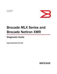
BI4XGBI4XGBI24CBI24CBI24C16TX RX TX RX TX RX TX RXTX RX TX RX TX RX TX RX12BigIron RX-8NETWORKS7131819242530313637424348AC OK DC OK ALMEJECT SYS AC OK DC OK ALMEJECT SYS AC OK DC OK ALMEJECT SYS AC OK DC OK ALMBI24CBI24CBI24CBI24CBI24CBI4XGBI4XGTX RX TX RX TX RX TX RXTX RX TX RX TX RX TX RXEJECT SYSChapter 1: Networking Basicswork Layer protocol sending the packet is the same Network Layer protocolreceiving it. After all, you wouldn't want an <strong>IP</strong> packet processed by <strong>IP</strong>X on thereceiving side, would you?Media Access Control (MAC)This sublayer introduces its own addressing method, similar to the NetworkLayer. But where the Network Layer's addressing is considered logical, theData Link Layer is considered physical. Every device on the network has somepiece of hardware that allows it to communicate to the network called a NetworkInterface Controller (NIC). For most hardware, that NIC has a Data LinkLayer address within its hardware. It's like a serial number imprinted by themanufacturer. It's not as permanent as a serial number, and there are ways inmost operating systems to temporarily override and change the number. Inmost circumstances, you won't. This is the NIC's physical address. The logicaladdress (the Network Layer address) is assigned and can be easily changed. Itis the physical address that the Data Link Layer uses to carry out the NetworkLayer's orders.Why two addresses? Remember that the Data Link Layer is local. The physicaladdress stays within the local network. It does not go outside the boundary ofthe broadcast domain (more on this later). The logical address spans allboundaries. It is meant to traverse many broadcast domains, networks, and soon. Think of the physical address as similar to the last seven digits of a telephonenumber (in the United States). If you're making a local call, you usuallyonly need to dial seven numbers. But what if you want to call someone in a differentstate, or a different country? You need additional numbers to get youthere (area codes, country prefixes, etc.). You need a higher level layer, a logicallayer. Networking works the same way.The Data Link Layer takes the packet from the Network Layer, and creates aframe. The frame includes the source physical address (of the sender) and thedestination physical address of the next physical device in the path to get tothe logical address destination. What happens if a packet has to travel throughseveral networks to get to its destination? At each physical device, that passesthe packet from network to network, the frame information is dropped andnew frame information is created. The packet itself remains unaltered. I thinkthis could be best summed up with another picture.RouterframePacketheaderNewframePacketheaderPacketframe header18 Brocade <strong>IP</strong> Primer
The Physical Layer (Layer 1)One other feature in a lot of Data Link Layer protocols is error correction. Thereare a lot of physical media to choose from (as we will discuss more in the nextsegment). Some media are very reliable. Some are not. A Data Link Layer protocoldoes well to know what the next layer is. In many cases, it will anticipatethe unreliability and employ error correction to compensate.Of all the Data Link Layer protocols there are, clearly Ethernet is the one that isbest known. It is an extremely common protocol, and we'll be discussing it inmore detail later in this chapter. Some other examples include Token Ring,Asynchronous Transfer Mode (ATM), and High-Level Data Link Control (HDLC).The Physical Layer (Layer 1)Well, we made it. After all the work that's been done in the upper six layers, thefinished frame is handed from the Data Link Layer to the Physical Layer. ThePhysical Layer is the layer that does the actual transmitting of data. This is thelayer where the data actually moves. You can think of the upper six layers as“getting the data ready.” When it reaches Layer 1, “it goes.”The Physical Layer takes the frame from the Data Link Layer and converts it tobits. We'll go into this much more in Chapter 2, but for now, all you need toknow is that it's a long stream of 1's and 0's.0110111000101011011100001010111Once converted to bits, the Physical Layer uses its physical media to conveythe data. There are a lot of different ways to do this. Some physical protocolssend electrical signals across copper wire. Some physical protocols send alaser signal across fiber optics. Some protocols generate pulses of microwavesinto the air. Each different method has their advantages and disadvantages,but they all get the job done.Once the Physical Layer has sent its bits, the receiving Physical Layer picksthem up, shapes them into a frame, hands it off to the receiver's Data LinkLayer, and we start the journey back up the stack. The Physical Layer has doneits job. It's the layer that actually sends the data.Examples of Physical Layer protocols include Unshielded Twisted Pair (UTP),Fiber, IEEE 802.11 (wireless networking), and so many other variations. Therehave been people that have demonstrated the ability to network using carrierpigeons. You don't typically get as much bandwidth that way as you would with,say, fiber, but the point is, it doesn't matter. Whatever suits your need. Whetheryou need to beam signals to an orbiting satellite and back to Earth, or whetheryou're using two cans and a string, the Physical Layer sends the data.And that's the OSI Reference Model, folks. Next, I'd like to talk about a DataLink Layer Protocol that anyone reading this book is going to have to get reallycozy with.Brocade <strong>IP</strong> Primer 19
Chapter 1: Networking BasicsEthernetEthernet was the brain child of an engineer named Bob Metcalfe, and wasdeveloped in the mid-1970s. The concept of networking was clearly in itsinfancy. There were some, at the time, who considered the design of Ethernetto be an utter failure waiting to happen. It's funny how some things work out,isn't it? Today, Ethernet is easily the most popular Data Link Layer protocolthere is.While Ethernet is technically a Data Link Layer protocol, there is also a mechanismassociated with it that is technically Physical Layer. It's called CarrierSense Multiple Access/Collision Detection (CSMA/CD). When Ethernet firststarted, it used a single coaxial cable that connected to every single computerin the network. It looked liked this:The coaxial cable has one thin strand of copper in the middle of it, surroundedby quite a bit of insulation. This is surrounded by an additional meshwork ofcopper, which is, in turn, surrounded by more insulation. This cable is designedto carry an electrical signal. The Ethernet NIC (in the computer) generates anelectrical signal on the cable. This signal is interpreted by the receiving EthernetNIC as a binary 0 or a binary 1.The problem is that only one NIC could generate an electrical signal at a time.There was only one medium (the cable). To deal with the possibility that twomachines on the network might try to send a signal at the same time, collisiondetection was invented. The transmission process worked like this:1. Convert the frame to binary digits and prepare it for transmission2. Check to see if the medium (the cable) is idle (there's no signal); if it is notidle, wait until it is3. Start transmitting your signal4. Check for a collision; if there's a collision:a. Continue the transmission for a certain period of time so that everymachine on the network realizes there's a collisionb. Stop transmitting and wait for a random amount of timec. Try transmitting again (start at Step 2)5. The signal has been transmitted20 Brocade <strong>IP</strong> Primer
Layer 1 Ethernet (Cabling)What if a collision was detected, you waited for a random amount of time, triedagain, and you still got a collision? Well, you just kept on trying. There are amaximum number of collision retries in the protocol in which it will declare afailure and give up, but until it reaches that threshold, it just keeps trying.So there's the CSMA/CD. You have the carrier sense. This is what detects themedium and decides whether or not it's idle. The multiple access is the processlisted above. This allows many computers to use the same medium(cable, in this example). And finally, the collision detection is a set of proceduresto follow if two (or more) computers attempt to use the medium at thesame time.Many times, CSMA/CD is compared to a group of people talking in a room. In awell-behaved room, one person talks while the others listen. If anyone elsewants to talk, they wait until the speaker is done talking (carrier sense). Asoften happens, two people may attempt to talk at the same time (a collision).When that happens, each person stops talking, and waits to see if the otherwill begin speaking. If they don't, given a polite amount of time, one will starttalking, and the conversation will continue.Well, now that you know how Ethernet communicates with the physical media,let's look at the different physical media you can use with Ethernet.Layer 1 Ethernet (Cabling)What did that say? Layer 1 Ethernet? I thought Ethernet was a Layer 2 protocol!It is. Calm down. I deliberately named this section. This is because thereare many common physical media that have become synonymous with Ethernet.And while, technically, Ethernet is strictly Layer 2, a vast majority of theindustry will commonly refer to Ethernet hardware, and you need to be awareof what they mean.CoaxialAs I mentioned in the previous section, Ethernet started life on coaxial cables.The ends of the cable looked like this:Brocade <strong>IP</strong> Primer 21
Chapter 1: Networking BasicsThis connector is called a BNC connector. To have multiple machines connectedto the network, you needed to have T-connectors to allow a coaxialcable to be connected from the computer into the main line. At the end of themain line, you had a terminator. This was a terminating resistor that reflectedthe signal back through the cable.This is called a bus topology. This signal travels back and forth along the mainline. Every machine that is attached to the main line sees the frames thatevery other machine sends, but it only pays attention to the ones addressed toitself. This topology has plenty of weaknesses.For one, the bus topology doesn't expand very well. A single length of coaxialcable is only rated for 185 meters. If the cable is longer than that, the signalwill experience attenuation. This is the distance beyond which the electricalsignal will be so weak that it won't be properly detected. When an electrical signalis sent along the copper, it will immediately start “losing steam.” The signalwill become weaker and weaker the farther it goes. After 185 meters on acoaxial line, the signal will become so weak, other devices in the chain won'treally be sure there's a signal there. It becomes unreliable beyond that point.Another weakness in the bus topology is that if there's a break anywhere in themain line, the whole network is down. Think of an electrical circuit. If there's abreak in the cable, there's a break in the circuit. Now, no computer is talking toanybody. Network Administrators in yon days of yore will likely reflect on the ol'coaxial network days and shudder. Compared to what we have now, they werea nightmare to maintain.Twisted PairWhat do we have now? Well, the most common medium is called twisted pair.This comes in many varieties. On the high level, there's Unshielded TwistedPair (UTP) and Shielded Twisted Pair (STP). STP is expensive, and the shieldingcan make it difficult to bend or shape. On the other hand, the additionalshielding does a better job of preventing outside interference. UTP is, by far,the most common. They both come in different grades called categories. Someof the most common categories include category 3, category 5, category 5e,and category 6. These are most commonly abbreviated to CAT3, CAT5, CAT5e,and CAT6. CAT5 uses thicker cables inside than CAT3. It also has more twistsper meter. Likewise with CAT5e and CAT6, the higher the number, the thickerthe copper cables and the more twists per meter. Also, the higher the category,the greater the performance. CAT3 is only rated for 10 Mbps Ethernet, whileCAT5e and CAT6 are required for gigabit. There are many more than these, butthese are the categories you're most likely to deal with.22 Brocade <strong>IP</strong> Primer
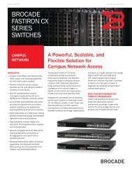
Layer 1 Ethernet (Cabling)Twisted Pair is actually a bundle of eight smaller cables-four pairs. Each pair istwisted around each other many times throughout the length of the cable. Thecables are twisted to help block crosstalk. This would be when the electricalsignal on one of the other pairs crosses over to any of its neighboring pairs. Italso helps to minimize electromagnetic interference (EMI). Any time an electricalcircuit is rapidly changing signals, EMI becomes the by-product. It's a signalfield emitted by the circuit, and it can interrupt other nearby legitimate circuits,if you're not careful. STP is still used for this purpose. This adds additionalinsulation and EMI shielding.The cable comes to an end called RJ45. As you can see from the diagram, ithas eight metal positions called pins. Each pin connects with one of the eightwires inside the cable.You may, or may not, have noticed that the eight cables inside are aligned in acertain order. This conforms to one of two standards put forth by the TelecommunicationsIndustry Association/Electronic Industries Association (TIA/EIA).The standard is called TIA/EIA-568-B.1-2001. It specifies that there are twomethods for aligning the cables. They are labeled T568A and T568B. Casually,these are referred to as the A-standard and B-Standard.To see which standard a particular cable uses, hold the RJ45 end in front ofyour face with the clip-side away from you. Then, read the colors from left toright.T568A1 White with Green stripe2 Green3 White with Orange stripe4 Blue5 White with Blue stripe6 Orange7 White with Brown stripe8 BrownT568B1 White with Orange stripe2 Orange3 White with Green stripe4 Blue5 White with Blue stripe6 Green7 White with Brown stripe8 BrownBrocade <strong>IP</strong> Primer 23
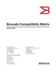
Chapter 1: Networking BasicsT568AT568B1. White with Green stripe 1. White with Orange stripe2. Green 2. Orange3. White with Orange stripe 3. White with Green stripe4. Blue 4. Blue5. White with Blue stripe 5. White with Blue stripe6. Orange 6. Green7. White with Brown stripe 7. White with Brown stripe8. Brown 8. BrownWhich one do you use? In the end, the important thing is to be consistent. Ifyou are using the A-standard, always use the A-standard. If you are using the B-standard, always use the B-standard. This is especially true of the cable itself.If you have used the A-standard on one end of the cable, use the A-standardon the other end of the cable. There's one exception that I'll talk about in aminute.For Ethernet 10Base-T and 100Base-T, only pins 1, 2, 3, and 6 are important.The first pair, 1 and 2, is used to transmit data. The second pair, 3 and 6, isused to receive data. In the A-standard, transmitting is the green pair andreceiving is the orange pair. In the B-standard, it's the opposite. The orangepair transmits, and the green pair receives. The blue pair and brown pair areunused.As I mentioned earlier, a standard Ethernet cable is one that has the samestandard arrangement of cables on both ends of the cable. This is commonlyreferred to as a straight-through cable. This is because a signal sent on pin 1on one side will be received on pin 1 of the other side; a signal sent on pin 2on one side will be received on pin 2 of the other side; and so forth. This cableis used to plug a computer (or most any other device) into an Ethernet hub orswitch.But what if we need to connect two hubs or switches together? Or what if wewant to directly connect two computers together? You would use what is calleda crossover cable. The crossover cable uses one standard on one side, but theopposite standard on the other. For example, if you were using the T568A standard,you would create a crossover cable by making one end of the cable A-standard, and the other end of the cable B-standard. You're matching yourtransmit pair directly to the receiving pair of the other side.24 Brocade <strong>IP</strong> Primer
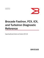
Console49F Link 50F1 3 5 7 9 1113 15 17 19 21 2325 27 29 31 33 3537 39 41 43 45 47Power1F 2F 3F 4F2 4 6 8 10 1214 16 18 20 22 2426 28 30 32 34 3638 40 42 44 46 48Layer 1 Ethernet (Cabling)If you've never had to make or use a crossover cable, don't be too surprised.Many NIC manufacturers have added a technology to automatically sensewhether a crossover signal is needed or not. It simply compensates for whateverhardware is in place. Brocade switches are included in this. While it istechnically proper to use a crossover cable when connecting two Brocadeswitches, it is not necessary. The switches are intelligent enough to know whatyou meant to do.Twisted pair networks use a star topology. At the center of the star is a hub orswitch. All of the participants in the network plug into the star.SwitchUnlike the bus topology, this is very expandable, and can accommodate virtuallyany number of hosts you may need. If a cable is broken, only oneparticipant is negatively affected. The rest of the network may carry on. A disadvantageto this topology is that now the hub or switch becomes a singlepoint of failure. If it goes down, the network goes down. There are methods ofprotecting yourself from this kind of failure which we will discuss in laterchapters.Twisted pair can achieve throughput of up to gigabit (1000 Mbps) speeds.Unfortunately, like coaxial, it has an attenuation limit as well, and it's shorter.Signal is rated for up to 100 meters.FiberWhat if you need lengths of cables much longer than 100 meters? Or what ifyour facility has a lot of EMI? Here comes fiber.The major advantages with fiber are its attenuation limit (up to 70 km) and,because it uses light rather than electricity, it's invulnerable to EMI. It can alsoachieve much greater speeds than its copper counterparts. The current maximumis 10 Gbps, but technology is always moving forward. Speeds of 100Gbps or more are realistically not too far away. And the media that will bringthese speeds to you? Fiber.Brocade <strong>IP</strong> Primer 25
Chapter 1: Networking BasicsThe main disadvantage to fiber is that it's expensive. The cables are made bycombining fiber optic strands and insulating them. A laser light generates thesignal. The more powerful the laser, the longer the attenuation limit. There aretwo varieties you need to make yourself familiar with:• Multimode Fiber (MMF)— 1000 Mbps (SX) attenuation: 550 meters— 10 Gbps (SR) attenuation: 300 meters• Single-mode Fiber (SMF)— 1000 Mbps (LX) attenuation: 5 km— 1000 Mbps (LHA) attenuation: 70 km— 10 Gbps (LR) attenuation: 10 km— 10 Gbps (ZR) attenuation: 70 kmThe distance you can achieve with fiber depends on the type of fiber you use,the speed of the protocol, and the type of laser. Gigabit fiber uses a connectorcalled a Gigabit Interface Converter (GBIC). Brocade uses a smaller version ofthis connector called a mini-GBIC. On the switch that supports a gigabit fiberinterface, there will not be a port to plug a cable into. There will only be anopen module slot. This slot houses the mini-GBIC. The mini-GBIC contains theport that you plug the cable into. There are four different mini-GBICs you couldpurchase for this slot:• 1000SX (used with multimode fiber)• 1000LX (used with single-mode fiber)• 1000LHA (used with single-mode fiber)• 1000TX (used with twisted pair copper)This provides a great deal of flexibility for the customer. If the purpose of theswitch port changes over time (say, we want to go from 1000SX to 1000LHA),the customer doesn't need to purchase a new switch. They just need toreplace the mini-GBIC.The cable terminates using either an SC or an LC connector. The SC is an olderconnector. It can still be found in some equipment, but it has largely beenreplaced by the smaller LC connector. Brocade’s mini-GBICs and 10G portsuse LC connectors.26 Brocade <strong>IP</strong> Primer
Layer 1 Ethernet (Cabling)SC connectorLC connectormini - GBICHubWith twisted pair, you need to have some way to have more than two computersshare information with each other. In the beginning, this device was calleda hub.A hub is a device with many RJ45 ports on it. As a device, it's not remarkablyintelligent. It has a very straight-forward purpose. Whenever it receives an electricalsignal on one of its ports, it replicates that signal out all of its other ports.That's it.This method is similar, in some respects, to the bus topology we talked aboutearlier. All of the computers connected to the hub (or the main line, in bustopology) saw all of the frames that were sent. It didn't matter whether theframes were meant for that computer or not, it saw them. Now, by default, theEthernet protocol ignores the frames not specifically addressed for its ownNIC. Still, though, you can see that this is a fairly inefficient way to communicate.It's also potentially insecure.SwitchWhile hubs still exist, you will find that, more commonly, they have beenreplaced by the switch. The switch looks very similar to a hub. It's a device withseveral RJ45 ports on it. What sets it apart is that it has a brain (a CPU). Wherea hub is strictly a Physical Layer device (it just replicates the signal), a switch isa Data Link Layer device.When the switch receives a signal on one of its ports, it keeps track of physicaladdresses connected to it. It then has an address book to draw from. When asignal comes in, the switch checks to see what physical address the frame isbound for. It will then look at its address book to see if it knows what physicalport (of itself) the destination physical address is connected to. If the switchfinds the destination address, it will forward the frame out of that port and onlythat port. If the switch doesn't find the destination address in its address book,it will act like a hub, and forward the frame out all of its ports. The difference isthat the switch will pay attention to replies. If the switch gets a response framefrom the destination address, it will add that address to its address book andremember it for next time.Brocade <strong>IP</strong> Primer 27
Chapter 1: Networking BasicsSwitches provide another wonderful advantage over hubs. They are capable ofsomething called full-duplex communication. This is the concept of transmittingdata and receiving data at the same time. We'll talk much more about thisa little later in the chapter.Layer 2 Ethernet (Addressing)Now we know how Ethernet is typically laid out physically. Let's talk more aboutthe protocol itself.MAC AddressWe talked about addressing in the Data Link Layer section. Ethernet uses a48-bit (6 byte) number to uniquely identify every physical device. This addressis called the Media Access Control (MAC) address. It is typically represented inhexadecimal (because writing out 48 1s and 0s makes for a very long number),and looks like this: 46:72:69:6E:6B:21. Different operating environmentsrepresent MAC addresses differently, but the number is the same. For example,Brocade represents the MAC address by separating it into two-byte pairs.The same number would be represented this way: 4672.696E.6B21.With 48 bits, you can represent over 281 trillion unique addresses. While thisnumber looks big and intimidating, there is a rhyme and reason to it. Theaddress is split into two 24-bit sections. The first 24-bits are assigned by theInstitute of Electrical and Electronics Engineers (IEEE). This 24-bit number isreferred to as an organizationally unique identifier (OUI). Every legitimateEthernet hardware manufacturer has at least one of these OUIs. Larger manufacturershave several. The second part of the address (the last 24-bits) is aunique identifier created by the manufacturer. It's the unique serial number ofthe device. This gives the company 16,777,216 unique addresses per OUI.46 : 72 : 69 : 6E : 6B : 21OUI Unique ID46 : 72 : 69 6E : 6B : 21So, if we take a look at an example MAC address, 46:72:69:6E:6B:21, we cansee that the OUI of the manufacturer is 46:72:69, and that the NIC's uniqueidentifier (assigned by the manufacturer) is 6E:6B:21. There are software programsavailable that will help you identify the OUI with a known manufacturer.This can be very valuable when troubleshooting problems on your network.28 Brocade <strong>IP</strong> Primer
Layer 2 Ethernet (Addressing)Ethernet FrameWe've mentioned the concept of a Data Link Layer frame frequently in thischapter. Let's take a good look at an Ethernet frame.Preamble8 bytesDestinationaddress6 bytesSourceaddress6 bytesLength/Type2 bytesData46 to 1,500 bytesFramechecksequence4 bytesEthernet FrameAs you can see, the IEEE 802.3 Ethernet frame is broken up into six sections.Let's get to know each one individually:Preamble. This is an 8-byte section of alternating 1s and 0s. It provides a 5MHz clock to help synchronize the sender and receiver for the coming bitstream.Destination Address (DA). This is a 6-byte (48-bit) number. It is the MACaddress of the device that the frame is being sent to.Source Address (SA). This is a 6-byte (48-bit) number. It is the MAC address ofthe device sending the frame.Length/Type Field. This is a 2-byte field that can either be a Length Field or aType Field. If the number is smaller than 1,536 (0x600 in hexadecimal), it is aLength Field, and the number describes how many bytes of the Data field areused as the IEEE 802.2 LLC header. If the number is greater than 1,536, it is aType Field. The number identifies what Network Layer protocol should processthe frame (0x0800, for example, is <strong>IP</strong>). If this is a Length Field, the type will bedescribed in the LLC header.Data. This is the data. This is the packet that was handed down from the NetworkLayer. This can be any length from 46 bytes to 1,500 bytes, using astandard Maximum Transmission Unit (MTU). As mentioned in the previousfield, this may contain an IEEE 802.2 LLC header as part of the field.Frame Check Sequence (FCS). This is a 4-byte (32-bit) number. It is a cyclicalredundancy check (CRC) that is calculated using the DA, SA, Length, and Datasections. When the frame is created, the CRC is calculated and applied to theend of the frame. On the receiving end, the receiver recalculates the CRC andmakes sure that it matches with the FCS that was sent. This allows for errorchecking.These are the individual pieces that make up each Ethernet frame. The framereveals where it's coming from, where it's going to, how long it is, and, finally, achecksum to make sure the receiver got the data that the sender intended. So,now that we're communicating, let's talk about how to communicate moreefficiently.Brocade <strong>IP</strong> Primer 29
Chapter 1: Networking BasicsHalf-duplex vs. Full-duplexEthernet uses two ways to communicate from one machine to the next. Let'slook at them both.Half-duplexRemember when we talked about the early days of Ethernet? It used a bustopology (several computers connected to one cable)? This worked okay, but itonly provided half-duplex communication. Half-duplex is the polite way to communicate.You don't speak while the other person is talking (in this case, youcan't). One device speaks at a time.Think of half-duplex as a train on a railroad track. The train can obviously onlymove in one direction, and there can't be any other trains on the track. If thereare, that could cause a collision.Half-duplexSendor Receiveor Collision!As we described earlier, when a collision occurs, both talkers stop talking, andwait for a random period of time before they try again. This is certainly a politeway to communicate, but it's not very efficient. But because the cable couldonly carry one signal, that's all the original Ethernet could do. One electricalsignal. One train. One track.Hubs run into a similar problem. These are incapable of anything other thanhalf-duplex communication as well. They simply repeat the signal, much likethe main cable of the bus topology (even though a hub would make it a startopology).A group of computers connected to a hub (or even several hubs) would be considereda collision domain. This defines an area in the network wherecollisions may occur. Just like two people trying to have a conversation in acrowded room, the more people in the room, the greater the possibility thattwo people will be trying to talk at the same time (collision). As you can imag-30 Brocade <strong>IP</strong> Primer
Half-duplex vs. Full-duplexine, this would make it harder and harder to hold a conversation. For bestnetwork efficiency, one should always minimize the size of the collisiondomain (or, if possible, eliminate it completely).Full-duplexWhat if you could listen and talk at the same time? Wouldn't that be great?This is called full-duplex communication. If we go back to the railroad example,now you've got two railroad tracks that are parallel to each other. On one, wehave a train traveling in one direction. On the other, we have another train travelingin the opposite direction.SendFull-duplexReceiveFull-duplex is not only efficient, but it takes away the risk of collisions. Recallthat using twisted pair, you only needed two pairs (of the four pairs) for 10/100 Mbps Ethernet. When using full-duplex, one pair is used to transmit data,and the other pair is used to receive data. You completely eliminate the risk ofhaving two devices wanting to use the same pair at the same time. Each pairhas its purpose, and travels in only one direction.But we can't use a hub for full-duplex communication. For full-duplex, you haveto have a switch. When using a switch with full-duplex communication, you'veessentially eliminated your collision domain. Each device plugged into theswitch has its own private communication channels to and from the switch.A switch can operate at half-duplex. In fact, most switches will give you theoption to configure the speed (10 Mbps, 100 Mbps, 1000 Mbps) and duplex ofeach port. For example, you could have one port set at 100 Mbps full-duplex,and another set to 10 Mbps half-duplex. Why would you want to do this? Well,there may be some places you may work that are dependent on older equipment.Some of this equipment may only be capable of half-duplexcommunication. If you have such equipment, and it's plugged into a switchconfigured to be half-duplex, collisions are still possible. Fortunately, they'll becontained within the switch and the half-duplex equipment. No other elementsof the network will be affected. Here, the collision domain exists between thenode (the half-duplex equipment) and the switch port it's plugged into.AutonegotiationIt didn't take long for manufacturers to realize that all of these different settings(speed, duplex, etc.) may confuse a majority of their customers. In themid-90's, autonegotiation became the mainstream default setting for bothswitch ports and NICs. Autonegotiation uses Physical Layer electrical pulses toinvestigate what speed and what duplex it can operate at. If you have a switchBrocade <strong>IP</strong> Primer 31
Chapter 1: Networking Basicsport that is set to autonegotiate, and you have a workstation with a NIC that'sset to autonegotiate, and you plug the workstation into the switch port, electricalpulses will be sent to detect what the highest speed and duplex setting thetwo network devices can communicate on.Let's say you have a 100 Mbps full-duplex NIC and a 100 Mbps full-duplexswitch, and both are set to autonegotiate. When you connect these devicestogether, they should “autonegotiate” to operating at 100 Mbps full-duplex.They negotiate or agree to operate at these settings. What if your NIC was 10Mbps half-duplex, but your switch was still 100 Mbps full-duplex? Using autonegotiationon both sides, the connection will communicate at 10 Mbps halfduplex.The NIC and switch negotiated, and the switch realized that 10 Mbpshalf-duplex was the best that the NIC could communicate at. They negotiated.Sounds great, doesn't it? Well, there's a downside to it. Suppose you have aworkstation with a 100 Mbps full-duplex NIC set to autonegotiation. You plug itinto a switch which is configured to 100 Mbps full-duplex, but is not set toautonegotiate. It is configured specifically to communicate at 100 Mbps fullduplex.It is forced to 100 Mbps full-duplex, as they say. What happens? Well,typically, the NIC will correctly deduce the speed (100 Mbps, in this example),but won't get the expected responses when negotiating duplex. Just like in reallife, it's difficult to negotiate with someone who won't negotiate with you. TheNIC fails to detect the duplex setting, so it fails to the lowest common denominator-half-duplex. So, in the end, you have a switch that is configured tocommunicate at 100 Mbps full-duplex, and a NIC that has autonegotiated tofunction at 100 Mbps half-duplex. This is called a duplex mismatch.The duplex mismatch occurs more times than you might think. The result isthat the switch believes it can talk and receive at the same time, and the NICdoesn't. What's going to happen? Well, frames will certainly be lost. Dependingon the upper layer protocols (the Transport Layer, most likely), the data will stillget there, but very slowly. With the errors and dropped frames, the TransportLayer will have to resend segments many times to make sure all of the datareaches the destination.What can you do with a duplex mismatch? You have two options:1. Change the NIC's setting so that it is also forced to communicate at 100Mbps full-duplex.2. Change the switch port's setting so that it will autonegotiate.While autonegotiation seems like a great idea, its success still depends on allthe devices involved being configured the same way. In real world experience,you'll also find that different manufacturers have different ideas about howautonegotiation should work. The result is that you could have a NIC set toautonegotiate and a switch port set to autonegotiate and you could still end upwith a duplex mismatch!What's a poor network engineer to do? Well, it's similar to the duplex mismatchsolution listed above. In the end, you need to make a decision as to which oneyou will use.32 Brocade <strong>IP</strong> Primer
Brocade Ethernet Switches & RoutersYou could set all of the devices and switch ports to autonegotiation all thetime. If you do this, you won't have to worry about changing so many settings,certainly. Almost all network equipment (NICs, switches, etc.) are set to autonegotiateby default. The downside is that, unless your equipment is all madeby one manufacturer, you may run into autonegotiation failures that will createduplex mismatches. You may also run into problems with someone bringing inoutside equipment (say, a consultant bringing in a laptop) that is forced to fullduplex(autonegotiation is off).You could set all of the devices and switch ports to be forced to full-duplex allthe time. You won't have to worry about autonegotiation failures this way. It willrequire a lot more setup time, though. All existing switch ports and NICs willhave to be configured to full-duplex. Any new machine or switch will have to beconfigured to full-duplex before it's put into use. And you'd still have the riskmentioned in the previous paragraph. What if a consultant brings in a laptopthat's configured for autonegotiation?Each solution has its advantages and disadvantages. Every experienced engineerwill have his or her preferred method of dealing with the problem.Experience will teach you what is best for you.Well, now we know the technologies. Let's take a look at what Brocade has tooffer us.Brocade Ethernet Switches & RoutersBrocade offers a complete line of enterprise and service provider Ethernetswitches, Ethernet routers, application management, and network-wide securityproducts. With industry-leading features, performance, reliability, andscalability capabilities, these products enable network convergence andsecure network infrastructures to support advanced data, voice, and videoapplications. The complete Brocade product portfolio enables end-to-end networkingfrom the edge to the core of today's networking infrastructures. Tolearn more about Brocade products, visit http://www.brocade.com.Summary• The OSI Reference Model describes how machines can talk to oneanother• The OSI Reference Model consists of seven layers:— Application gets data from the user— Presentation formats the data to a certain standard— Session keeps track of which conversation the data belongs to— Transport makes sure the data gets to its destination— Network decides what path the data will take to get to its destinationon a logical levelBrocade <strong>IP</strong> Primer 33
Chapter 1: Networking Basics— Data Link prepares data for physical transmission, and decides howthe data will get to its destination on a physical or local level— Physical the method that actually transports the data• Ethernet is a very popular Data Link layer protocol• Ethernet is usually cabled using either coaxial, UTP, or fiber• Ethernet is usually in a star topology, centrally connected to a hub orswitch• MAC address is the physical address of the Ethernet device• Half-duplex communication can only listen or speak at one time• Full-duplex communication can listen and speak simultaneouslyChapter Review Questions1. What layer of the OSI Reference Model interacts with the user?a. Physicalb. Presentationc. Applicationd. Data Link2. What address is considered the physical address of a device in Ethernet?a. MAC addressb. LLC addressc. <strong>IP</strong> addressd. <strong>IP</strong>X address3. What layer of the OSI Reference Model makes sure the data reaches itsdestination?a. Networkb. Physicalc. Sessiond. Transport4. What does autonegotiation decide?a. The speed and duplex of the communicationb. The MAC address of the NICc. The physical mediad. The <strong>IP</strong> address of the host34 Brocade <strong>IP</strong> Primer
Chapter Review Questions5. What layer of the OSI Reference Model decides how the data will get to itsdestination?a. Physicalb. Applicationc. Networkd. Presentation6. On the Data Link layer, what form is the data in?a. Segmentsb. Framesc. Packetsd. Bits7. What layer of the OSI Reference Model actually sends the data?a. Applicationb. Networkc. Data Linkd. Physical8. On the Transport layer, what form is the data in?a. Segmentsb. Framesc. Packetsd. Bits9. Which layer of the OSI Reference Model keeps track of the different conversationsthat may be occurring?a. Presentationb. Data Linkc. Physicald. Session10. On the Network layer, what form is the data in?a. Segmentsb. Framesc. Packetsd. BitsBrocade <strong>IP</strong> Primer 35
Chapter 1: Networking BasicsAnswers to Review Questions1. c. The user sends the data to the Application layer, and it is the Applicationlayer that finally presents the data to the user in a reply.2. a. The Media Access Control (MAC) address is the physical address of anEthernet device.3. d. The Transport layer uses different methods (depending on the protocol)to make sure the data gets to its destination.4. a. Autonegotiation decides what speed (10 Mbps, 100 Mbps, etc.) andwhat duplex (full or half) the Ethernet communication will use.5. c. It's the Network layer's job to decide, logically, how the data will get toits destination.6. b.The Data Link layer works with frames.7. d. The Physical layer is the one that actually creates an electrical, optical,or other physical signal and transports the data.8. a. The Transport layer works with segments.9. d.The Session layer keeps track of the different conversations.10. c. The Network layer works with packets.36 Brocade <strong>IP</strong> Primer
TCP/<strong>IP</strong>2The most popular protocol stack to date is TCP/<strong>IP</strong>. It gained a great deal ofpopularity as more and more people and businesses started using the Internet.The Internet uses TCP/<strong>IP</strong> as its protocol suite. As a result, manybusinesses have adopted TCP/<strong>IP</strong> for their internal networks as well.Some might ask what layer TCP/<strong>IP</strong> resides in. It doesn't, really. TCP/<strong>IP</strong> is not aspecific protocol. It is a collection of different protocols, extending from Layer 3(Network) to Layer 7 (Application). In this chapter, I will introduce you to the twolayers in the TCP/<strong>IP</strong> protocol stack that you will want to be most comfortablewith: Layers 3 & 4.Layer 3 TCP/<strong>IP</strong>: <strong>IP</strong>As the title shows, the Layer 3 (Network) protocol in TCP/<strong>IP</strong> is called InternetProtocol (<strong>IP</strong>). This is the main protocol, but it is not the only protocol in the TCP/<strong>IP</strong> Network Layer. As we said in the previous chapter, the Network Layer's job isto decide how the data will get to where it needs to go. I also mentioned that ituses addressing, networks, and routing protocols to accomplish its task. We'regoing to look at each of these in detail in this section.But first, let's take a look at what we're dealing with in Layer 3. This layer wouldhave received the segment from Layer 4 (Transport). <strong>IP</strong> adds a few bytes of itsown to the front of the segment to make it a packet. These bytes are referredto as the <strong>IP</strong> header. The header is subdivided this way:HeaderVersionLength4 bits4 bitsToS8 bitsTotalLength16 bitsIdentifier16 bitsFlags3 bitsFrag.Offset13 bitsTimeProtocolTo-Live 8 bits8 bitsHeaderChecksum16 bitsSource<strong>IP</strong> Address32 bitsDestination<strong>IP</strong> Address32 bits<strong>IP</strong>OptionDataVersion. This is a 4-bit number. In most networks, this number will be “4” (or0100, in binary; more on this later). The current version of <strong>IP</strong> is referred to as<strong>IP</strong>v4 (or “<strong>IP</strong> version 4"). A new version, which is already gaining ground, is <strong>IP</strong>v6.Brocade <strong>IP</strong> Primer 37
Chapter 2: TCP/<strong>IP</strong>Header Length (HLEN). This is also a 4-bit number. It represents the length ofthe header, but it uses a 32-bit (4-byte) word as its unit. For example, mostheaders are 20 bytes long. To represent this as 4-byte words, this numberwould be 5 (5 x 4 bytes [32-bits] = 20 bytes).ToS with <strong>IP</strong> Precedence Bits. This is one byte (8 bits). The first three bits arepriority bits. They're used to set <strong>IP</strong> Precedence. The next four bits describe thepacket's Type of Service (ToS). This allows for special instructions in handlingdifferent types of packets. The last bit is unused.Total Length. This is a 16-bit (2 byte) number. It is the length (in bytes) of theentire packet, including the header and the data that follows.Identifier. This is a 16-bit (2 byte) number that uniquely identifies the packet.Flags. This is a 3-bit field. Should the packet need to be fragmented, it will beindicated here.Frag Offset. This is a 13-bit number. If the packet is too large to fit on a singleframe, it will be fragmented. The offset will help in reassembling the packet.Time-To-Live (TTL). This is an 8-bit (1 byte) value that is set when the packet isgenerated. The idea is that if the packet doesn't get to its destination beforethe TTL expires, the packet is dropped. This is a safeguard to keep the networkfree of orphaned packets (e.g., packets that never get to their destination buthop from router to router to router).Protocol. This is an 8-bit (1 byte) value that indicates the <strong>IP</strong> Protocol. Thisnumber could represent a Network Layer protocol, or it could represent theTransport Layer protocol that generated the segment (and that will need to processthe segment on the other side). Some well-known values here are: 1(ICMP), 6 (TCP), 17 (UDP), 50 (ESP) and 89 (OSPF).Header Checksum. This is a 16-bit cyclical redundancy check (CRC) of theheader. It allows the receiving side to make sure the header arrived intact.Source <strong>IP</strong> Address. This is the 32-bit address of the device that created thepacket.Destination <strong>IP</strong> Address. This is 32-bit address of the device that the packet isto be delivered to.<strong>IP</strong> Option. This field is typically used for testing and low-level networkdebugging.Data. This is the segment received from the Transport Layer.You can see from this that <strong>IP</strong> uses 32-bit addresses. These are usually separatedinto four 8-bit numbers separated by periods. They are also usuallyrepresented in decimal (base 10). An example of an <strong>IP</strong> address might be:192.168.100.1.38 Brocade <strong>IP</strong> Primer
Console49F Link 50F1 3 5 7 9 1113 15 17 19 21 23 25 27 29 31 33 3537 39 41 43 45 47Power1F 2F 3F 4F2 4 6 8 10 1214 16 18 20 22 24 26 28 30 32 34 3638 40 42 44 46 4849F Link 50FPowerConsole1 3 5 7 9 1113 15 17 19 21 23 25 27 29 31 33 3537 39 41 43 45 471F 2F 3F 4F2 4 6 8 10 1214 16 18 20 22 24 26 28 30 32 34 3638 40 42 44 46 48Thinking in BinaryI mentioned earlier that there are other Network Layer protocols in <strong>IP</strong>. Here area couple of the more well-known ones:Internet Control Message Protocol (ICMP) is used to send messages betweenLayer 3 devices. It can check to see if an address is responding. It can tellanother Layer 3 address that it's sending information too fast. It can help tracethe path through several routers. The most common use for ICMP is its echoprotocol, more commonly known as ping. This is a really simple protocol. Onedevice will send an “echo request” message to another device. If that device isactive, it will send an “echo reply” back to the first device. Simply stated, it's asif one device shouts out, “Hey, are you there?” And if the device is there, itresponds with, “Yeah, I'm here!”Hey, are you there?ICMP Echo RequestYeah, I’m here!ICMP Echo ReplyAddress Resolution Protocol (ARP) is used to match an <strong>IP</strong> address with a MACaddress. It kind of bridges the gap between the Data Link Layer and the NetworkLayer. We'll talk more about ARP later in the chapter.Thinking in BinaryThe numbers that we use in our daily lives (with rare exception) are decimal.This means base 10. What does “base 10" mean? It means we have ten digits(single numbers) we can use before we have to start using two digits. Forexample, we have the number 0 (zero). That's one number. We also have nineother numbers: 1, 2, 3, 4, 5, 6, 7, 8, and 9. If we're going to represent anynumber higher than that, we need to start using two-digit numbers (e.g., 10,11, 12, etc.). That's decimal, or base 10.Computers, overly simplified, are made of up of billions of transistors. Transistorsare electrical components that can be in one of two states. There's eithera voltage (electricity is passing through them), or there is no voltage (no electricityis passing through them). You can think of transistors like a light switch.The light switch is either on, or it's off. You've got two options.It didn't take computer engineers long to realize that they could use this anomalyto count. But we can only really represent two numbers: 0 (off) and 1 (on).So, how can that be useful? Well, if you're only talking about a single digit, itreally isn't very useful. But when you string a bunch of digits together, now youcan represent all kinds of numbers.Brocade <strong>IP</strong> Primer 39
Chapter 2: TCP/<strong>IP</strong>What we're talking about is binary. Binary is a way to represent numbers. It'slike decimal, but in decimal, we have ten digits. In binary, we have two. In decimal,you would count 0,1,2,3,4,5,6,7,8,9,10. In binary, you would count0,1,10. That last number looks like a number ten, doesn't it? It's not. If you'reusing binary, that number represents the number two.In decimal, each digit place represents a multiple of ten. For example, 10, 100,and 1000 represent ten (10 x 1), one hundred (10 x 10), and one thousand(10 x 10 x 10). If we see “10,000,” we know that as ten thousand (10 x 10 x 10x 10), because there's a “1” followed by four zeros. Binary works in a similarfashion, but instead of multiples of 10, it's multiples of two. For example, 10,100, and 1000 in binary represent two (2 x 1), four (2 x 2), and eight (2 x 2 x2). And if we were to take it one step further, “10000” would represent sixteen(2 x 2 x 2 x 2). As decimal is referred to as base 10, binary is referred to asbase 2.128 64 32 16 8 4 2 10 0 0 0 0 0 0 1Why am I telling you all of this? You'll find out very quickly. As I mentioned inthe previous chapter, switches and routers are computers. They have a CPU.They have RAM. As such, they also operate in binary.You would do very well to memorize the diagram on this page. It will help you inmore ways than just impressing your friends.The first example of using binary is in the <strong>IP</strong> address itself. I gave you an exampleof an <strong>IP</strong> address: 192.168.100.1. There are four decimal numbersseparated by a period. But what you need to know is that the computers,switches, and routers see that number this way:1100 0000 . 1010 1000 . 0110 0100 . 0000 0001Notice that each of the four decimal numbers are represented by eight binarydigits. You usually call a binary digit a bit. So, each of the four decimal numbersare represented by eight bits. Let's look at the first number: 1100 0000.You've got a 1 in the 128 bit place, and a 1 in the 64 bit place, and all the restare zeros. So, if you add 128 + 64, you'll see that you get the number 192.Likewise, the next number: 1010 1000. Here, we've got a 1 in the 128 bitplace, a 1 in the 32 bit place, and a 1 in the 8 bit place. This number, in decimal,would be 128 + 32 + 8, or 168. The third number is 0110 0100. This hasa 1 in the 64 bit place, a 1 in the 32 bit place, and a 1 in the 4 bit place. Thenumber is 64 + 32 + 4, which equals 100. And the last number's the easiest.You've only got one “1,” and it's in the 1 bit place. The binary number “00000001” equals our decimal “1.”Let's look at eight bits. To get the smallest possible number (with just eightbits), we could set all of the bits to 0, right? This would give us the number 0.To get the largest possible number, we could set all of the bits to 1. This wouldgive us the number 255 (128 + 64 + 32 + 16 + 8 + 4 + 2 + 1).40 Brocade <strong>IP</strong> Primer
Network Classes128 64 32 16 8 4 2 10 0 0 0 0 0 0 10000 0001 = 10000 0110 = 4 + 2 = 60010 1000 = 32 + 8 = 400110 0100 = 64 + 32 + 4 = 1001100 0000 = 128 + 64 = 1921100 1000 = 128 + 64 + 8 = 2001111 1010 = 128 + 64 + 32 + 16 + 8 + 4 + 2 = 2501111 1111 = 128 + 64 + 32 + 16 + 8 + 4 + 2 + 1 = 255By the way, eight bits are referred to as one byte (yes, nerds think they're veryfunny). You can think of the diagram above as either eight bits, or one byte.What does this mean with our <strong>IP</strong> address? Well, we see that each of the fournumbers (192.168.100.1, for example) is actually represented by eight bits (orone byte). So for each of the four numbers, the smallest number it can be is 0,and the largest number it can be is 255. You will never see an <strong>IP</strong> address thatlooks like this: 359.278.913.4. All of the digits (besides the last one) are biggerthan 255. They would require more than eight bits to represent them. Thismeans that the smallest possible <strong>IP</strong> address is 0.0.0.0, and the largest possible<strong>IP</strong> address is 255.255.255.255.An <strong>IP</strong> address is a 32-bit number. As I mentioned previously, it is usually representedby four 8-bit numbers separated by periods. On top of that, the four 8-bit numbers are usually converted to decimal. Rarely will you see anyone referringto an <strong>IP</strong> address as “1100 0000 . 1010 1000 . 0110 0100 . 0000 0001.”You will almost always see it as “192.168.100.1.”Network ClassesNow we know what an <strong>IP</strong> address is. What's next? Well, the authors of TCP/<strong>IP</strong>wanted to use the 32-bit number of the address to represent both the network(group of <strong>IP</strong> addresses) and the host (the specific address of the host). Let'scompare this to the Post Office delivering a letter. The address on the lettersays, “123 Fake Street.” Now that's one line, but it represents two things forthe postman. For one, the postman knows the house is on Fake Street. FakeStreet has a lot of houses on it. It's a group of houses, just like a network is agroup of hosts. It's the “123” part of the address that tells the postman todeliver it to a specific house. An <strong>IP</strong> address works the same way. It has a networkportion (like the street name) and a host portion (like the specific house).How do we distinguish which part is the network and which part is the host?Whenever you configure a device with an <strong>IP</strong> address, you must include oneother number called a subnet mask. The subnet mask is also a 32-bit numberthat is usually represented by four 8-bit numbers separated by periods. It isalso usually represented in decimal, but its meaning is far more clear whenseen in binary. If we go back to our previous example of an <strong>IP</strong> address,192.168.100.1, we could accompany that with a subnet mask ofBrocade <strong>IP</strong> Primer 41
Chapter 2: TCP/<strong>IP</strong>255.255.255.0. Looks like an <strong>IP</strong> address, doesn't it? Instead, it actually showsus (and the networking equipment) which part of the <strong>IP</strong> address is the networkand which is the host. Let's look at it in binary:Address – 192.168.100.1Subnet Mask – 255.255.255.0Address: 1100 0000 . 1010 1000 . 0110 0100 . 0000 0001Subnet Mask: 1111 1111 . 1111 1111 . 1111 1111 . 0000 0000Notice that from left to right, the subnet mask shows every bit to be “1” until itgets to the 25th bit. The 25th bit is “0,” and so are the rest of the bits to theend. The subnet marks all of the bits that belong to the network with a “1,” andit marks all of the bits that belong to the host with a “0.”The first 24 bits (in this case) mark the network address:Address – 192.168.100.1Subnet Mask – 255.255.255.0Address: 1100 0000 . 1010 1000 . 0110 0100 . 0000 0001Subnet Mask: 1111 1111 . 1111 1111 . 1111 1111 . 0000 0000Network Address: 1100 0000 . 1010 1000 . 0110 0100 . 0000 0000In Decimal: 192 . 168 . 100 . 0And the last 8 bits mark the host address:Address – 192.168.100.1Subnet Mask – 255.255.255.0Address: 1100 0000 . 1010 1000 . 0110 0100 . 0000 0001Subnet Mask: 1111 1111 . 1111 1111 . 1111 1111 . 0000 0000Host Address: 0000 0000 . 0000 0000 . 0000 0000 . 0000 0001In Decimal: 0 . 0 . 0 . 1In every properly formed subnet mask, you will notice the first few bits startingwith a string of “1”'s, and the remaining bits as “0”'s. Again, the ones show thenetwork portion of the <strong>IP</strong> address, and the zeros show the host portion. In thisexample, the address is 192.168.100.1 with a subnet mask of255.255.255.0. The network portion is 192.168.100, and the host portion is.1. Because of this subnet mask, 24 bits are used to represent the network,and the last 8 bits are used to represent the host. Remember that with 8 bits,you can represent numbers from 0 (all 8 bits are “0”) to 255 (all 8 bits are“1”). This gives you a clue as to how many hosts you can have belonging to thissame network (group of <strong>IP</strong>s).42 Brocade <strong>IP</strong> Primer
Network ClassesWhat we haven't talked about yet, though, is that you can't quite use all of thenumbers from 0 to 255 to assign to hosts. When you define a network, twoaddresses are reserved. They are referred to as the network address and thebroadcast address.The network address is when the host portion is all zeros. In our example, thenetwork portion of “192.168.100.1 subnet mask 255.255.255.0” is192.168.100. The host portion is .1. This tells us that we have eight bits for ourhost portion. If all eight of those bits are zero, that represents the networkaddress, and it cannot be assigned to a device as a legitimate address. In thisexample, the network address would be 192.168.100.0. Notice that the networkportion of the address stayed the same. Only the host portion changed,and it is all zeros. This number identifies the network.The second address that already has a special purpose is the broadcastaddress. This is defined when the host portion is all ones. In our example, weknow that we have eight bits to use to define a host address. If all of those bitsare one, we get this number: 192.168.100.255. Notice, again, that I did notchange the first 24 bits. I just changed the last eight, and I made them allones. The broadcast address is used when you want to send a message toevery address in the network.So, in our example, we have eight bits to use for the hosts. With eight bits, wecan represent numbers from 0 to 255 for a total of 256 numbers (rememberto include 0). But we can't use “0,” because it's the network address. Thatleaves 255 numbers we can use, but we can't use “255” because that's thebroadcast address. That leaves us with a total of 254 numbers to use. We canuse any number from 1 to 254. In our example, we used 1 (192.168.100.1). Ifwe wanted to configure another device, and we wanted it to be in the samenetwork, we could assign it 192.168.100.2, or 192.168.100.15, or192.168.100.213. I think you get the idea. But to be absolutely certain thatthe <strong>IP</strong> address would be in the same network, we have to use the same subnetmask (in our example, it would be 255.255.255.0). If you have two addressesthat look similar, but they have different subnet masks, they are in differentnetworks.You can always calculate how many hosts you can have by looking at the numberof bits. In our example, we have eight bits for the host portion. You couldcalculate how many hosts you can use by using this formula: 2n - 2. So, if wehave eight host bits, that would be 28 - 2. As 28 = 256, that would be thesame as 256 - 2, which equals 254 hosts. The “28” is the total number ofhosts we could represent. We subtract two (and always two) for the networkand broadcast address.When TCP/<strong>IP</strong> was formed, they divided all the possible <strong>IP</strong> addresses intoclasses. Each class would be specially defined, and each class would have adefault subnet mask.Brocade <strong>IP</strong> Primer 43
Chapter 2: TCP/<strong>IP</strong>Table 1. Classful RoutingClassFirst FewBits of theAddressFirst OctetRange(in decimal)Subnet MaskNetworkHost perNetworkA 0 0-127 255.0.0.0 128 16,777,214B 10 128-191 255.255.0.0 16,384 65,534C 110 192-223 255.255.255.0 2,097,152 254D 1110 224-239E 1111 240-255Class A. This class is defined by the very first bit in the address being zero. Ifthat first bit is zero, it is a Class A network address. Because the first bit has tobe zero, that means any address from 0.0.0.0 to 127.255.255.255 is consideredto be Class A. Class A's default subnet mask is 255.0.0.0. This meansthat only the first 8 bits are used for the network portion, and the last 24 bitsare used for the host. This means that, in the same Class A network, you couldhave 224 - 2, or 16,777,216 - 2, which equals 16,777,214 hosts. As you cansee, this is a class that allows you to have a few different networks, but eachnetwork could have a lot of hosts in them. To calculate the number of networksyou could create, you would leave out the first bit (as that defines the class).This leaves you with seven bits, and 27 = 128 networks, or the numbers from0 to 127.Class B. This class is defined by the very first bit in the address being a one,but the second bit must be a zero. This means that any address from128.0.0.0 to 191.255.255.255 is considered a Class B. Class B's default subnetmask is 255.255.0.0. This makes it fairly even-handed. You have 16 bitsfor the network portion, and 16 bits for the hosts. This would mean that youcould have 216 - 2, or 65,536 - 2, which would give you 65,534 hosts. Now, fornetworks, you have to leave out the first two bits (as they define the class; aone followed by a zero). This leaves you with 14 (16 - 2) bits, and 214 = 16,384networks. These would be the network portions from 128.0 to 191.255.Class C. This class is defined by the very first bit and the second bit being one,followed by the third bit being a zero. This means that any address from192.0.0.0 to 223.255.255.255 is considered to be a Class C. The defaultClass C subnet mask is 255.255.255.0 (look familiar?). This means that thefirst 24 bits are the network portion, and the last 8 bits are for the hosts. As weshowed in our earlier example, with eight bits you could have 28 - 2, or 256 - 2,which gives you 254 hosts. For networks, however, you have to leave out thefirst three bits (as they define the class; “110” for the first three bits). Thisleaves you with 21 (24 - 3) bits, and 221 = 2,097,152 networks. These wouldbe the network portions from 192.0.0 to 223.255.255. As you can see, thisgives you a lot of networks with fewer hosts per network.44 Brocade <strong>IP</strong> Primer
BI4XGBI4XGBI24CBI24CBI24C16T X RX T X RX T X RX T X RXT X RX T X RX T X RX T X RX12BigIron RX-8NETWORKS7131819242530313637424348AC OK DC OK ALMEJECT SYS AC OK DC OK ALMEJECT SYS AC OK DC OK ALMEJECT SYS AC OK DC OK ALMBI24CBI24CBI24CBI24CBI24CBI4XGBI4XGT X RX T X RX T X RX T X RXT X RX T X RX T X RX T X RXEJECT SYSBI4XGBI4XGBI24CBI24CBI24C16T X RX T X RX T X RX T X RXT X RX T X RX T X RX T X RX12BigIron RX-8NETWORKS7131819242530313637424348AC OK DC OK ALMEJECT SYS AC OK DC OK ALMEJECT SYS AC OK DC OK ALMEJECT SYS AC OK DC OK ALMBI24CBI24CBI24CBI24CBI24CBI4XGBI4XGT X RX T X RX T X RX T X RXT X RX T X RX T X RX T X RXEJECT SYSThe SubnetClass D. This class is defined by the first bit, second bit, and third bit all beingone, followed by the fourth bit being a zero (do you see a pattern yet?). Thismeans that any address from 224.0.0.0 to 239.255.255.255 is considered tobe a Class D. Class D is a special class that is reserved for multicast (moreabout this in Chapter 9). You should not create networks or hosts in this space.It is reserved.Class E. This class is defined by the first bit, second bit, third bit, and fourth bitall being one. This means that any address from 240.0.0.0 to255.255.255.255 is considered to be Class E. Class E is also a special classthat is reserved. You should not create networks or hosts in this space.The Internet uses only Classes A, B, and C for address space. As mentioned intheir descriptions, Class D and E are reserved for special purposes, and arenot to be used as addressable space on the Internet.For a while, the default subnet masks were the only ones used. This maderouting remarkably easy. All a router had to do to determine class was to lookat the first few bits of the <strong>IP</strong> address. It could easily identify Class A, B, C, D, orE. This is referred to as classful networking.But soon, problems started to arise. As the Internet grew in popularity, itbecame clear that there would not be enough addresses to go around. In addition,there were many addresses that were being wasted. Consider this:RouterRouterT14.0.0.1200.0.0.1200.0.0.25.0.0.14.0.0.05.0.0.0Here we have a T1 line connecting two points. To create an <strong>IP</strong> network to theconnect the two points, we want to use the class with the smallest number ofhosts available to it. If you look at the previous table, this would be a Class C(254 hosts). But as you can see, this wastes 252 hosts. We only need two. Thisis only one example of the problems that occur using only classful networking.The SubnetThe answer came with the invention of the subnet. Simply stated, a subnet is aportion of a network within a network. It allowed for the creation of muchsmaller networks where needed.Let's take the example we mentioned in the previous section. You have twoendpoints connected by a T1 line. You want to create an <strong>IP</strong> network to connectthe two points, but you don't want to waste addresses. Let's say, you want touse the Class C network 192.168.100.0. Remember that a Class C networkhas a subnet mask of 255.255.255.0, or 24 bits for the network, and 8 bits forBrocade <strong>IP</strong> Primer 45
BI4XGBI4XGT X RX T X RX T X RX T X RXT X RX T X RX T X RX T X RX6 12 18 2430 36 42 48BigIron RX-8NETWORKS1 7 13 1925 31 37 43BI24CBI24CBI24CAC OK DC OK ALMEJECT SYS AC OK DC OK ALMEJECT SYS AC OK DC OK ALMEJECT SYS AC OK DC OK ALMBI24CBI24CBI24CBI24CBI24CBI4XGBI4XGT X RX T X RX T X RX T X RXT X RX T X RX T X RX T X RXEJECT SYSBI4XGBI4XG6 12 18 2430 36 42 48BigIron RX-8NETWORKS1 7 13 1925 31 37 43BI24CBI24CBI24CT X RX T X RX T X RX T X RXT X RX T X RX T X RX T X RXAC OK DC OK ALMEJECT SYS AC OK DC OK ALMEJECT SYS AC OK DC OK ALMEJECT SYS AC OK DC OK ALMBI24CBI24CBI24CBI24CBI24CBI4XGBI4XGT X RX T X RX T X RX T X RXT X RX T X RX T X RX T X RXEJECT SYSChapter 2: TCP/<strong>IP</strong>the hosts. This gives us 254 usable hosts (remember to subtract the networkand broadcast address). We only need two hosts, so using the default subnetmask is pretty wasteful. What if we used 255.255.255.252 as the subnetmask? In binary, this would be 1111 1111 . 1111 1111 . 1111 1111 . 11111100. This means that 30 bits are used for the network portion and only twobits are left for the hosts. This gives us 22 - 2, or 4 - 2, which equals 2 hosts.Perfect! So, with the subnet mask of 255.255.255.252, the network addressis 192.168.100.0, one host is 192.168.100.1, the other host is192.168.100.2, and 192.168.100.3 is the broadcast address.RouterT1192.168.100.2mask 255.255.255.252Router4.0.0.1192.168.100.1mask 255.255.255.2525.0.0.14.0.0.05.0.0.0This is referred to as classless networking, as you're not conforming to classes.You can subdivide (or subnet) as much as you need. Remember that this is adivision. You can't make the subnet mask smaller than the default for theclass. For example, you can't define a Class C network to have a subnet maskof 255.255.0.0 (or 16 bits for the network portion). A Class C subnet musthave at least 24 bits for the network portion. Likewise, a Class B subnet musthave at least 16 bits for the network portion, and a Class A network must haveat least eight bits for the network portion.Let's try another example. Let's say we have a network that will require 400hosts. If we use a Class C, the largest number of hosts we can have per networkis 254. We could use a traditional Class B, but this would give us 65,534hosts, a lot more than we need. So, let's start with a Class B, say, 172.16.0.0with a subnet mask of 255.255.0.0. We've got to create a subnet to allow for400 hosts. We know that eight host bits gives us 254 hosts. How many doesnine host bits give us? This would be 29 - 2, or 512 - 2, which would equal 510hosts. This is still more than we need, but it's the smallest subnet we canmake that will still meet our requirement. If we have nine host bits, that leavesus 23 (32 - 9) network bits. With 23 network bits, this gives us a subnet maskof 1111 1111 . 1111 1111 . 1111 1110 . 0000 0000, or, in decimal,255.255.254.0. So, our final network address is 172.16.0.0 with a subnetmask of 255.255.254.0. The first usable address would be 172.16.0.1. Thelast usable address would be 172.16.1.254. The broadcast address would be172.16.1.255.46 Brocade <strong>IP</strong> Primer
The SubnetTable 2. Understanding SubnetsNetworkAddressSubnetMaskFirst UsableAddressLast UsableAddress172.16.0.0 255.255.254.0 172.16.0.1 172.16.1.255Broadcast AddressNumber of Usable Hosts172.16.1.255 510Why would we want to shrink the host size of a network? Why not just useclassful networking? There's another reason. Your host size determines yourbroadcast domain. Remember how we talked about a broadcast address? Thisis an address that you send a message to that every device in the subnet willreceive.How Does the Network Layer Know Where to Go?We talked a little bit about ARP (Address Resolution Protocol). ARP is a greatexample of a broadcasting protocol. Let's say, we're using a Class A network:10.0.0.0. Because we're using classful networking, its subnet mask would be255.0.0.0. This means eight bits are for the network portion, and 24 bits arefor the host portion. Let's say we have 4,000 devices in this network. Whenone device wants to talk to the other, the Network Layer on the sourcemachine will first check to see if the destination device is in the same network.If it is not, the Network Layer will check the source machine's routing table.A routing table exists on any Layer 3-capable device. This includes workstations.You don't believe your PC has a routing table? Pull up a commandprompt and type: netstat -rn.$ netstat -rnKernel <strong>IP</strong> routing tableDestination192.168.222.0127.0.0.00.0.0.0Gateway0.0.0.00.0.0.0192.168.222.1Genmask255.255.255.0255.0.0.00.0.0.0FlagsUUUGMSS000Window000irtt000Ifaceeth0loeth0This command will work on most modern operating systems. If not, your operatingsystem will have a way for you to view your machine's routing table. Thetable contains network addresses in one column, and how to get there in theothers. It includes the address of a gateway, as well as which interface theframe should be created on, to get to its destination. A gateway is a device thatis either connected to both networks directly, or it’s a device that knows how toget to a remote network that it's not connected to.Brocade <strong>IP</strong> Primer 47
Chapter 2: TCP/<strong>IP</strong>“Why does my PC already have entries in the routing table? I didn't add these!”Technically, when you configured the <strong>IP</strong> address on your PC, you did. When youconfigure a NIC with an <strong>IP</strong> address, say, 10.0.0.4 with a subnet mask of255.0.0.0, the operating system adds an entry for the 10.0.0.0 network with asubnet mask of 255.0.0.0, and shows that the destination is...the NIC you configured.In this case, the destination doesn't have to be a gateway, becauseyou're connected to the network.It is also common (though not required) to see a default gateway. This cansometimes be shown as a destination network address of 0.0.0.0. Essentially,it acts as a catch-all. You're basically saying, “Hey, if I don't know how to getsomewhere (I don't have the network address in my routing table), send it tothis guy.” Typically, the default gateway is a router. By standard convention, thedefault gateway must be in the same network as the device using it. Why?Well, let's go back to our example. We talked about what would happen if thehost were trying to communicate to another host that was not in the same network.What if the host were trying to communicate to another host that was inthe same network? Let's say we want to reach 10.0.0.10. The Network Layerwill now check another table-the ARP table. Most operating systems will showyou your machine's ARP table when you type: arp -a.$ arp -ajasper.springfield (192.168.100.2) at 00:0C:BC:49:E2:F0 [ether] on eth0abe.springfield (192.168.100.3) at 00:04:08:DE:FC:01 [ether] on eth0gateway.springfield (192.168.100.1) at 02:04:08:10:2C:A0 [ether] on eth0The first column shows you the <strong>IP</strong> addresses that are in the same network(that your workstation knows about). The second column shows you the MACaddress that belongs to each specific <strong>IP</strong> address. If the destination <strong>IP</strong> addressis listed in the ARP table, the Network Layer knows that if it sends its packet tothe Data Link Layer, it will be able to properly create a frame (with the correctdestination MAC address).But what if the address you want to communicate with isn't in the ARP table?The Network Layer sends an ARP broadcast. The ARP broadcast is addressedto the broadcast address of the network. In our example, the network is10.0.0.0 with a subnet mask of 255.0.0.0. This means that the broadcastaddress for this network is 10.255.255.255. So the ARP broadcast is sentfrom the workstation (10.0.0.4) to the broadcast address (10.255.255.255).When the Data Link Layer receives this packet (the ARP broadcast), it uses theworkstation's MAC address as the source address, but it uses a broadcastMAC address as the destination. The broadcast MAC address sets all 48 of thebits in the address to “1.” In hexadecimal, it looks like this: FF:FF:FF:FF:FF:FF.The broadcast calls out “Hey, I'm 10.0.0.4, and I need to know the MACaddress of 10.0.0.10. Will the host 10.0.0.10 send me a reply and tell me yourMAC address?” This message is sent to every host in the 10.0.0.0 subnet, orevery host in the broadcast domain.48 Brocade <strong>IP</strong> Primer
Console49F50FLinkPower1 3 5 7 9 1113 15 17 19 21 2325 27 29 31 33 3537 39 41 43 45 471F 2F 3F 4F2 4 6 8 10 1214 16 18 20 22 2426 28 30 32 34 3638 40 42 44 46 48Console49F Link 50F1 3 5 7 9 1113 15 17 19 21 2325 27 29 31 33 3537 39 41 43 45 47Power1F 2F 3F 4F2 4 6 8 10 1214 16 18 20 22 2426 28 30 32 34 3638 40 42 44 46 48The SubnetTypically, 10.0.0.10 will now send an ARP response. This message basicallysays, “Hey, 10.0.0.4! I'm 10.0.0.10, and my MAC address is01:23:45:67:89:AB.” The response is sent directly to 10.0.0.4, not the wholesubnet. How does 10.0.0.10 know the MAC address of 10.0.0.4? Easy. It wasin the ARP broadcast that it sent. The host 10.0.0.10, when it received the ARPbroadcast message, added the address 10.0.0.4 and its MAC address into itsown ARP table. When the ARP response reaches 10.0.0.4, the host 10.0.0.4will add 10.0.0.10 and its MAC address (01:23:45:67:89:AB) into its ARPtable. Now, it can send the packet that it originally wanted to send, knowingthat the Data Link Layer will be able to form a proper frame.source01:23:45:GF:CD:AB10.0.0.4ARP BroadcastdestinationFF:FF:FF:FF:FF:FF10.255.255.25501:23:45:EF:CD:AB10.0.0.4255.0.0.0destinationFF:FF:FF:FF:FF:FF10.255.255.255Hey, I’m 10.0.0.4, and I need toknow the MAC address of 10.0.0.10.Will you tell me this MAC address?01:23:45:67:89:AB10.0.0.10255.0.0.001:23:45:32:15:AF10.0.0.8255.0.0.0By default, the information stays in the ARP table for five minutes. If the informationis used, the timer is reset. After five minutes, it is removed from thetable. If the host wants to communicate with it again, it will need to sendanother ARP broadcast. Now, when you're dealing with three or four workstations,this may not seem like a big deal. But picture 4,000 workstations.destination01:23:45:GF:CD:AB10.0.0.4ARP Responsesource01:23:45:67:89:AB10.0.0.1001:23:45:EF:CD:AB10.0.0.4255.0.0.001:23:45:67:89:AB10.0.0.10255.0.0.0Hey, 10.0.0.4!I’m10.0.0.10, and my MAC address is01:23:45:67:89:AB01:23:45:32:15:AF10.0.0.8255.0.0.0Brocade <strong>IP</strong> Primer 49
Console49F Link 50FPower1F 2F 3F 4F123456789101112131415161718192021222324252627282930313233343536373839404142434445464748Console49F Link 50F1 3 5 7 9 1113 15 17 19 21 2325 27 29 31 33 3537 39 41 43 45 47Power1F 2F 3F 4F2 4 6 8 10 1214 16 18 20 22 2426 28 30 32 34 3638 40 42 44 46 48Console49F Link 50FPower1F 2F 3F 4F123456BI4XGBI4XGBI24CBI24CBI24C78910111213141516171819202122232425262728129306313233343536373839404142434445464748T X RX T X RX T X RX T X RXT X RX T X RX T X RX T X RX12BigIron RX-8NETWORKS7131819242530313637424348AC OK DC OK ALMEJECT SYS AC OK DC OK ALMEJECT SYS AC OK DC OK ALMEJECT SYS AC OK DC OK ALMBI24CBI24CBI24CBI24CBI24CBI4XGBI4XGT X RX T X RX T X RX T X RXT X RX T X RX T X RX T X RXEJECT SYSConsole49F Link 50FPower1F 2F 3F 4F123456789101112131415161718192021222324252627282930313233343536373839404142434445464748Chapter 2: TCP/<strong>IP</strong>Hey, I’m10.0.0.10!Hey, I’m10.0.0.10!Hey, I’m10.0.0.10!Hey, I’m10.0.0.10!Hey, I’m10.0.0.10!Hey, I’m10.0.0.10!Hey, I’m10.0.0.10!Hey, I’m10.0.0.10!Hey, I’m10.0.0.10!ARP is not the only broadcast protocol, but it is very commonly used. You canbegin to see why it might be a good idea to break some of these nodes up intomultiple broadcast domains.If the workstation wants to send a packet to a destination that is not on thesame network, the packet will still show the source and destination <strong>IP</strong>addresses, but the Network Layer will instruct the Data Link Layer to use thedestination MAC address of the gateway. This way, the gateway can pass thepacket to where it needs to go. The gateway will strip off the frame header andtrailer it received, and it will create a new frame header and trailer containingits MAC address as the source, and the destination <strong>IP</strong> address' MAC addressas the destination. Perhaps we need another illustration.Hey, I’m10.0.0.10!Hey, I’m10.0.0.10!Hey, I’m10.0.0.10!Hey, I’m10.0.0.10!Hey, I’m10.0.0.10!Hey, I’m10.0.0.10!Hey, I’m10.0.0.10!Hey, I’m10.0.0.10!Hey, I’m10.0.0.10!Hey, I’m10.0.0.10!Hey, I’m10.0.0.10!Hey, I’m10.0.0.10!Hey, I’m10.0.0.10!Hey, I’m10.0.0.10!Hey, I’m10.0.0.10!Hey, I’m10.0.0.10!Hey, I’m10.0.0.10!Hey, I’m10.0.0.10!Hey, I’m10.0.0.10!Hey, I’m10.0.0.10!Hey, I’m10.0.0.10!Hey, I’m10.0.0.10!Hey, I’m10.0.0.10!Hey, I’m10.0.0.10!Hey, I’m10.0.0.10!Hey, I’m10.0.0.10!Hey, I’m10.0.0.10!50 Brocade <strong>IP</strong> Primer
BI4XGBI24CT X RX T X RX T X RX T X RXBI4XGBI24CT X RX T X RX T X RX T X RXBI24C6 12 18 2430 36 42 48BI24CBigIron RX-8NETWORKS1 7 13 1925 31 37 43BI24CBI24CBIBI24C4XGT X RX T X RX T X RX T X RXBIBI24C4XGT X RX T X RX T X RX T X RXAC OK DC OK ALMEJECT SYS AC OK DC OK ALMEJECT SYS AC OK DC OK ALMEJECT SYS AC OK DC OK ALMEJECT SYSThe SubnetSource10.1.1.201:23:45:67:89:ABDestination192.168.100.202:04:06:08:0A:0CSource10.1.1.202:04:06:08:0A:DEDestination192.168.100.203:02:01:AB:CD:EFHost A10.1.1.2255.255.255.001:23:45:67:89:AB10.1.1.1255.255.255.002:04:06:08:0A:0C192.168.100.1255.255.255.002:04:06:08:0A:DEHost B198.168.100.2255.255.255.003:02:01:AB:CD:EFThis is why the gateway needs to be part of the same network as the host. Thehost needs to know how to get to the gateway. It will communicate to the gatewayusing its MAC address. If it doesn't know the MAC address, it sends anARP broadcast. If the gateway is not in the same network (or broadcastdomain), the gateway will never see the ARP broadcast. Broadcasts neverleave the broadcast domain. If the gateway never sees the ARP broadcast, itwill never reply to it. The gateway must have an address in the same networkas the hosts that use it.CIDRWith classless networking, there came a new way to label a network. Withclassful networking, you could see a network address of, say, 10.0.0.0, andyou would know that this was a Class A network, and therefore, its subnetmask must be 255.0.0.0. With classless networking, you could have a subnetlength of eight bits, 13 bits, 29 bits, almost anything! A new naming schemahad to easily reflect the subnet mask.Enter Classless Inter-Domain Routing (CIDR). It's usually pronounced like“cider.” The convention states that you can represent the number of networkbits in a subnet mask, by adding a number after a slash (“/”) character. Forexample, 10.0.0.0, in classful networking, has a subnet mask of 255.0.0.0(Class A). This means that the network portion has eight bits. Using CIDR, wewould represent this same network like this: 10.0.0.0/8. Notice that I used thenetwork address (10.0.0.0), followed it by a slash (/), and then followed that bythe number of network bits in the subnet mask (8, in this example).Using CIDR notation, you can easily represent any subnet. Let's look back at acouple of our previous examples. Remember the network that needed 400hosts? We came up with a subnet mask of 255.255.254.0, or 23 network bits.We used a Class B network to start with-172.16.0.0. The CIDR notation wouldbe 172.16.0.0/23. Or, how about the network where we only needed twohosts? We started with a Class C network, 192.168.100.0. We decided on asubnet mask of 255.255.255.252, or 30 network bits. The CIDR notationwould then be 192.168.100.0/30.Classless networking is the default today. Get to know CIDR notation well. It isnot only used throughout this book, it's used throughout the networking industry.It's a concise way to indicate the network address and the subnet mask ofa network.Brocade <strong>IP</strong> Primer 51
BI4XGBI4XGBI24CBI24CBI24C16T X RX T X RX T X RX T X RXT X RX T X RX T X RX T X RX12BigIron RX-8NETWORKS7131819242530313637424348AC OK DC OK ALMEJECT SYS AC OK DC OK ALMEJECT SYS AC OK DC OK ALMEJECT SYS AC OK DC OK ALMBI24CBI24CBI24CBI24CBI24CBI4XGBI4XGT X RX T X RX T X RX T X RXT X RX T X RX T X RX T X RXEJECT SYSBI4XGBI4XGBI24CBI24CBI24C16T X RX T X RX T X RX T X RXT X RX T X RX T X RX T X RX12BigIron RX-8NETWORKS7131819242530313637424348AC OK DC OK ALMEJECT SYS AC OK DC OK ALMEJECT SYS AC OK DC OK ALMEJECT SYS AC OK DC OK ALMBI24CBI24CBI24CBI24CBI24CBI4XGBI4XGT X RX T X RX T X RX T X RXT X RX T X RX T X RX T X RXEJECT SYSChapter 2: TCP/<strong>IP</strong>CIDR notation can also be used to indicate a specific host's subnet mask.Remember our two-host network? The CIDR notation is 192.168.100.0/30.The specific hosts can be represented this way: 192.168.100.1/30 and192.168.100.2/30. This not only indicates their specific address, but it alsotells us what their subnet mask is.RouterRouterT14.0.0.1/8200.0.0.1/30200.0.0.2/305.0.0.1/84.0.0.0/85.0.0.0/8As there is a subnet, there is also such thing as a supernet. This just allowsyou to group multiple addresses together, using CIDR notation. For example,let's say you're using 172.16.0.0/24, 172.16.1.0/24, 172.16.2.0/24, and172.16.3.0/24. Instead of individually referring to all four networks, you couldsimply refer to 172.16.0.0/22. You would not have assigned this as a subnetmask to hosts. It is purely used to refer to large groups of networks. Supernetsare not restricted to the minimum subnet mask length. For example, if Iwanted to represent 8.0.0.0/8, 9.0.0.0/8, 10.0.0.0/8, and 11.0.0.0/8, I couldrefer to the group as 8.0.0.0/6. Notice that the “6” is shorter than the minimumsubnet length of a Class A (“8”). This is okay, as the “6” is not really asubnet mask length, but a mask length to summarize all of the subnets withinthe range. This will come into play more when we starting talking about routingprotocols in Section III.Private Networks (RFC 1918)With classless networking, the Internet could grow and grow, but what aboutorganizations that may want to use TCP/<strong>IP</strong>, but may not want to use the Internet?For example, a business may have 500 workstations that their employeesuse to communicate locally (e.g., to file servers, internal servers, each other,etc.). If the business wanted to use TCP/<strong>IP</strong> for its network, it would have to registera network range with its proper registry for Internet numbers (seeChapter 13) in order for each workstation to have an <strong>IP</strong> address. Also, onceaddressed, each workstation could be accessible from anywhere on the Internet.This may not be desirable, if you have sensitive information on some ofyour servers or workstations.The Internet Engineering Task Force (IETF) publishes a set of standards calledRequest for Comments (RFC). These detail all kinds of different standards forthe Internet. Among them is RFC 1918: Address Allocation for Private Internets.This addresses (no pun intended) the problem by allowing privatenetworks to be created. You can still use TCP/<strong>IP</strong>, but you don't have to worryabout registering addresses with an Internet registry.52 Brocade <strong>IP</strong> Primer
Layer 4 TCP/<strong>IP</strong>: TCP/UDPRFC 1918 specifies a network range in each of the three addressable classes(A, B, and C).Table 3. RFC 1918Class Address RangeA 10.0.0.0/8 10.0.0.0 -10.255.255.255B 172.16.0.0/12 172.16.0.0 -172.31.255.255C 192.168.0.0/16 192.168.0.0 -192.168.255.255Because of the standard, Internet Service Providers (ISPs) know not to routethese particular addresses across the Internet. They are private. They aremeant to only be used locally. Today, many homes and business use theseranges of addresses. It's important for you to be familiar with them. You willuse them quite often. Memorize the above table.Layer 4 TCP/<strong>IP</strong>: TCP/UDPWe've made it all the way to Layer 4 (Transport). In the TCP/<strong>IP</strong> stack, the twomost common Transport Layer protocols are Transmission Control Protocol(TCP) and User Datagram Protocol (UDP). These are not the only TransportLayer protocols in the TCP/<strong>IP</strong> stack, but these are the ones that you'll be workingwith the most. Let's get started.First off, I should mention that the Transport Layer (Layer 4) also has anaddressing method. Layer 2 uses MAC addresses. Layer 3 uses <strong>IP</strong> addresses.Layer 4 uses ports. A port is a 16-bit number, meaning that it can represent anumber from 0 to 65,535. This part of TCP and UDP actually has a little hint ofbeing related to the Session Layer (Layer 5), because ports keep track of theconversation.Each port number represents a type of communication. Many ports are associatedwith specific Application Layer protocols. For both TCP and UDP, this portnumber range is 1 to 1023. These are services that are registered with theIANA. They are often referred to as well-known ports. Ports above 1023 areopen, but, for commercial applications that use them, it is most proper to registerthese with the IANA as well.Brocade <strong>IP</strong> Primer 53
Chapter 2: TCP/<strong>IP</strong>Table 4. Well-Known PortsPortServiceTCP 21TCP 22TCP 23TCP 25TCP/UDP 53UDP 67TCP 80TCP 110UDP 161TCP 443FTPSSHTelnetSMTPDNSDHCPHTTPPOP3SNMPSSLI should mention that just because a port number is registered to a particularApplication Layer protocol, it does not mean that you must use that applicationprotocol. For example, it is possible to use the SSH Application Layer protocolusing TCP 80, instead of TCP 22. It is possible to use HTTP using TCP 25,instead of TCP 80. It is possible to run SMTP using TCP 443, instead of TCP 25;however, if you did this, very few mail servers would be able to communicatewith your server properly. They would expect to be communicating with you onTCP 25. But the point is, it is possible. Just because a port is well-known or registeredto a particular application does not mean that only that application canbe used.With ports, one host (one <strong>IP</strong> address) may provide several services simultaneously.Say, for instance, that you wanted one host to be able to listen on TCP80 (HTTP), TCP 25 (SMTP), and UDP 53 (DNS). With ports, this is certainly possible.From the same client, you can address the same destination host, buttake part in multiple conversations in different services.UDP 53 “What’s the <strong>IP</strong> Address for www.brocade.com?”TCP 25 “I have an e-mail to send.”TCP 80 “May I see this web page?”What if a host wanted to initiate two (or more) conversations to the same hostusing the same service? You don't think this comes up? Ask any SystemsAdministrator. Let's say, you want to use SSH (TCP 22) to remotely connect to aserver. You've started a process in your first session, and you'd like to start asecond SSH session to the same server to perform another task. Both connec-54 Brocade <strong>IP</strong> Primer
Layer 4 TCP/<strong>IP</strong>: TCP/UDPtions will attempt to connect on TCP 22. Both connections will have the samesource <strong>IP</strong> address and the same destination <strong>IP</strong> address. How will eithermachine know which conversation is which?First off, the connection from the client to host uses TCP 22 as its destinationport. On the Transport Layer (just like addressing on the lower layers), youneed a source port and a destination port. What actually happened when youmade that SSH connection is that the client used TCP 22 for its destinationport, but it used another port number for its source port. The source port numberis a random number between 1024 and 65,535 that is chosen by theoperating system. Every time a new Transport Layer session is initiated, a newsource port is chosen. So, in our example, the first SSH connection will useone source port, and the second SSH connection will use a different sourceport.TCP src: 2000 dst: 22TCP src: 4000 dst: 22TCP src: 54321 dst: 22The source port is also used so that the destination host knows how to talkback to the client. Just like in Layer 3 (<strong>IP</strong>) and Layer 2 (MAC) addressing, theclient will initiate the connection to the destination host using a source portand a destination port, and the destination host will reply by reversing thesource and destination. This is probably seen best in an illustration.TCP src: 1024 dst: 22TCP src: 22 dst: 1024In this example, the client is initiating a SSH session to the server. The client'ssource port is TCP 1024 and its destination port is TCP 22. When the serverreplies, it uses a source port of TCP 22 and a destination port of TCP 1024.A session is distinguished by the following items:• Source <strong>IP</strong> address• Destination <strong>IP</strong> address• Source port• Destination port• Protocol (e.g., TCP or UDP)Both TCP and UDP use source and destination ports to distinguish the serviceand multiple sessions. Now let's see what makes them different.Brocade <strong>IP</strong> Primer 55
Chapter 2: TCP/<strong>IP</strong>Transmission Control Protocol (TCP)TCP is a connection-oriented protocol. As you may recall from the last chapter,this means that it goes to great lengths to make sure that the data gets to itsdestination. Remember our Transport Layer discussion in Chapter 1? To get itsjob done, TCP uses acknowledgments, windowing, and flow control. As arefresher, acknowledgments are used to make sure the data was delivered.Windowing tells the session how many segments should be sent before anacknowledgment is required. Flow control prevents the data from being senttoo fast.In every TCP session, there is a client and a server. The client is the host thatinitiated the connection. The client is requesting something from the server.Think of a client as a user going to a Web page. The client is the user requestingthe Web page. The server is the host that receives the request, anddelivers the data requested.TCP adds a header to the data it receives from the Session Layer. It's typically160 bits long, and it looks like this:Service Port16 bitsDestinationPort16 bitsSequence number32 bitsAcknowledgment number32 bitsDataReserved FlagsOffset6 bits 6 bits4 bitsWindow16 bitsChecksum16 bitsUrgent Printer16 bitsOptionsDataSource Port. This is a 16-bit number. As we mentioned before, the source portis used to help distinguish one session from another.Destination Port. This is a 16-bit number. This also participates in distinguishingone session from another, but it is most well known for defining what kindof Application Layer communication we intend to do.Sequence Number. This is a 32-bit number. Each of the segments is numbered.This is so the segments can be properly reassembled when they arereceived.Acknowledgment Number. This is a 32-bit number. When using windowing,this number is the next sequence number that the server expects.Data Offset. This is a 4-bit field. It specifies the size of the TCP header. Thenumber is in 32-bit words. The minimum size of the TCP header is 5 words(160 bits; 5 x 32 = 160). The maximum size is 15 words (480 bits; 15 x 32 =480).Reserved. This is a 6-bit field that is reserved for future use. All bits in this fieldshould be zero.56 Brocade <strong>IP</strong> Primer
Transmission Control Protocol (TCP)Flags. This is a 6-bit field. Each bit represents a special message in TCP.• URG Urgent pointer• ACK Acknowledgment• PSH Push function• RST Reset the connection• SYN Synchronize the sequence numbers• FIN Request to close the connection (finished)Window. This is a 16-bit number. It is the size of the window in bytes.Checksum. This is a 16-bit number. This provides error checking for TCP. Eachsegment has a checksum that allows the client to verify the data.Urgent Pointer. This is a 16-bit number. If the URG flag is set, this number actsas an offset to the sequence number.Options. This is an optional field that must be a multiple of 32-bits. It is usedin conjunction with the Urgent pointer. It provides additional settings.Data. This is the data received by the Session Layer.The 3-Way HandshakeTCP uses what's referred to as a “3-way handshake” to initiate a conversation.Let's start by showing you what it looks like.TCP SYNTCP SYN/ACKTCP ACKThe client sends a TCP SYN segment. The SYN is short for synchronize. It synchronizesthe segment sequence numbers between the client and the server,but it also initiates the session. The first packet (the SYN) determines whatdestination port you're communicating with, and what source port the servershould reply on.The server sends back a TCP SYN/ACK segment. To me, this is really a misnomer.It might be easier to think of this as an “ACK/SYN” packet. The “ACK” partis acknowledging the SYN that the client sent. The “SYN” part is the server'sSYN packet back to the client. It's as if the client is saying, “Hey, do you want totalk?” And the server replies, “Yeah, I want to talk. Do you want to talk?”And the client replies, “Yeah.” He does this by sending the third segment: anACK. An ACK, put simply, is an “I got it” segment. It's TCP's method for communicatingthat you've received a segment.Brocade <strong>IP</strong> Primer 57
Chapter 2: TCP/<strong>IP</strong>In summary, the 3-way handshake looks like this:1. Client sends TCP SYN to server2. Server sends TCP SYN/ACK to client3. Client sends TCP ACK to serverWindows and AcknowledgmentsNow you've initiated the session. It's time to start communicating. Here, the clientrequests some data. The server sends an acknowledgment (ACK) to tellthe client that it has received the request. Now the server will start sendingsegments.In our example, let's say that the server is going to send 20 kilobytes (20,480bytes) of data. The Transport Layer, on the server side, is going to divide that20 KB into several segments. It's going to number the segments so that the clientwill know how to reassemble them, and to make sure that it received themall. When the server starts sending segments, it will send a few at a time andwait for an acknowledgment from the client. This is the window.The window is measured in bytes, not segments. The server will send segmentsuntil it has reached the window size. In our example, let's say that thewindow size of the server is 5,120 bytes (5 KB). That means that the serverwill send segments until it has sent 5 KB worth of segments. Then it will wait toreceive an acknowledgment (ACK) from the client. When it does, it will sendanother 5 KB worth of segments, and so on.Request Data1 KB Segment1 KB Segment1 KB Segment1 KB Segment1 KB SegmentTCP ACK1 KB Segment1 KB Segment1 KB Segment1 KB Segment1 KB SegmentTCP ACK58 Brocade <strong>IP</strong> Primer
User Datagram Protocol (UDP)When it is finished communicating, the client will send a TCP FIN (request toclose) message to the server. The server will send an ACK to acknowledge theFIN. The server will send a message to its application to close the session, andthen it will send a TCP FIN/ACK segment to the client. Finally, the client willreply with an ACK segment to the server. It's as if the client is saying, “I want tostop now, okay?” The server replies with, “Okay,” followed by, “I'm stoppingnow, okay?” And finally, the client responds with, “Okay.” And this closes thesession. Any more communication between these two devices would result ina new 3-way handshake and, thus, a new session.In summary, the way TCP closes a session looks like this:1. Client sends TCP FIN to server2. Server sends TCP ACK to client, to acknowledge the FIN3. Server sends TCP FIN/ACK to client4. Client sends TCP ACK to serverTCP FINTCP ACKTCP FIN/ACKTCP ACKUser Datagram Protocol (UDP)UDP is a connectionless protocol. This means that there is no 3-way handshake,acknowledgments, windows, nor flow control. If the receiver gets thesegment, great. If it doesn't, too bad. We talked about this in Chapter 1, but itbears repeating. The reason that connectionless protocols are used is thatthey're very, very speedy.Think about TCP. You spend three segments just starting the session. Youspend untold number of segments sending acknowledgments. You spend timewaiting for acknowledgments. It even takes four segments just to finish. Oh,sure, your data gets there, and you know it gets there, but at a cost.In reality, in a perfect world, every protocol would be connectionless. It's fastand it's based on trust. How do I know my packet got to my destination?Because I sent it! That's how I know! Sadly, of course, networks just aren't thatreliable. To be fair, networks are a lot more reliable now than they used to be,and on a well-designed Ethernet switched network, UDP works great! Still,always keep this in mind: UDP is fast, but you might lose a few segments; TCPis slower, but it is safe.Brocade <strong>IP</strong> Primer 59
Chapter 2: TCP/<strong>IP</strong>UDP adds a Transport Layer header to create its segment, similar to TCP. Let'slook at UDP's header:SourcePort16 bitsDestinationPort16 bitsLength16 bitsChecksum16 bitsDataSource Port. This is a 16-bit number. You wouldn't think this would be necessarywith a connectionless protocol, and you're right. It's not...always. If noreply is expected, this number can be zero. If a reply is expected, it should bethe port number on which to expect the reply. It is very common for UDP protocolsto use the same source and destination ports for their communication.Destination Port. This is a 16-bit number. This can help distinguish whichApplication Layer protocol you're communicating with.Length. This is a 16-bit number. This number is the length, in bytes, of theentire segment (including the header). The minimum length is 8 bytes, as thiswould be the minimum size of the header with no data.Checksum. This is a 16-bit number. Believe it or not, this is a checksum of theentire segment. Wait a minute! Isn't UDP supposed to be unreliable? Yes, but itdoes provide a checksum to each of its segments. The checksum will verifywhether or not data has been altered or damaged in transport. What is doneabout that really depends on the Application Layer. There are some ApplicationLayer protocols that use UDP, but implement some reliability at Layer 7. Likewise,there are some Application Layer protocols that will even ignore thechecksum.Data. This is the data received by the Session Layer.Dynamic Host Configuration Protocol (DHCP)It's hard to have a conversation about UDP without talking a little bit aboutDHCP. DHCP is a protocol that is used to automatically configure a host with an<strong>IP</strong> address, subnet mask, default gateway, DNS configuration, and other network-relatedconfigurations. It uses UDP to do its job.For DHCP to work, you need to have a DHCP server. This can be an actualserver, a router, or any other network device that has DHCP-serving capability.The idea is that the DHCP server keeps a bank of usable <strong>IP</strong> addresses withinits subnet. When it receives a request, it leases out an address to the client. Itkeeps track of the life of the lease (which is configurable; it could be a week; itcould be five minutes). When the lease is at its half-way point, the serversends a packet to the client asking if it would still like to keep using theaddress. If it does, the lease timer is reset.Let's say you have a client that wants to receive an <strong>IP</strong> address. It needs to createa message to ask for one. DHCP uses UDP, so we have the Transport Layerfigured out. It sends a segment with a destination port of 67 (well-known portfor DHCP request).60 Brocade <strong>IP</strong> Primer
49F Link 50FPower11F 2F 3F 4F32Console5476981110131215141716191821202322252427262928313033323534373639384140434245444746 48Console49F Link 50F1 3 5 7 9 11 13 15 17 19 21 23 25 27 29 31 33 35 37 39 41 43 45 47Power1F 2F 3F 4F2 4 6 8 10 12 14 16 18 20 22 24 26 28 30 32 34 36 38 40 42 44 46 48BI4XGBI4XGBI24CBI24CBI24C16T X RX T X RX T X RX T X RXT X RX T X RX T X RX T X RX12BigIron RX-8NETWORKS7 131819242530313637424348AC OK DC OK ALMEJECT SYS AC OK DC OK ALMEJECT SYS AC OK DC OK ALMEJECT SYS AC OK DC OK ALMBI24CBI24CBI24CBI24CBI24CBI4XGBI4XGT X RX T X RX T X RX T X RXT X RX T X RX T X RX T X RXEJECT SYS49F Link 50FPower11F 2F 3F 4F32Console5476981110131215141716191821202322252427262928313033323534373639384140434245444746 48User Datagram Protocol (UDP)What about the Network Layer? What will it use for an address? For a sourceaddress, it will use, well, nothing: 0.0.0.0. For a destination address, it usesthe universal broadcast address: 255.255.255.255. This is a broadcastaddress no matter what subnet you may find yourself in.And what about the Data Link Layer? The frame will use the client's MACaddress (because that's burned into the NIC's ROM, remember?) as a sourceMAC address, and it will use the broadcast MAC address, FF:FF:FF:FF:FF:FF, asthe destination MAC address.The reply is sent on destination UDP port 68 (well-known port for DHCP reply).The DHCP server uses its own <strong>IP</strong> address and MAC for the source addresses.On the Network Layer, it uses 255.255.255.255 as the destination address,but it uses the proper destination MAC address in the frame. It learned theMAC address from the DHCP request. The reply contains all of the informationrequested, which usually includes at least an <strong>IP</strong> address, subnet mask, anddefault gateway.SourceUDP 670.0.0.012:34:56:78:9A“I need an <strong>IP</strong> address”DestinationUDP 67255.255.255.255FF:FF:FF:FF:FF:FFMAC+ 12:34:56:78:9ADestinationUDP 68255.255.255.25512:34:56:78:9A“Here’s an <strong>IP</strong> address”SourceUDP 6710.0.0.1032:10:FE:DC:BA:9832:10:FE:DC:BA:9810.0.0.10But notice, for the client to use DHCP, it must send a broadcast. This meansthat a DHCP server must have an address in the broadcast domain. What ifyou have several broadcast domains. Does this mean you have to have a DHCPserver in each domain?Well, you can do that, but most engineers find that using a DHCP helperaddress is the better way to go. This acts as kind of a DHCP proxy. The helperaddress is usually configured on the broadcast domain's gateway. Essentially,you're telling the router that it should listen for DHCP broadcasts. If it sees one,it should encapsulate it and send it to the DHCP helper address (wherever thatmay be), which is the address of the remote DHCP server. The DHCP serversends an encapsulated DHCP reply to the router, and the router sends thereply to the client. The client will not know that its broadcast ever left thebroadcast domain.SourceUDP 670.0.0.012:34:56:78:9A“I need an <strong>IP</strong> address” “Hey, this guy needs an <strong>IP</strong> address”DestinationUDP 67255.255.255.255FF:FF:FF:FF:FF:FFSourceUDP 67192.168.100.1DestinationUDP 6710.0.0.10MAC+ 12:34:56:78:9A192.168.100.1 10.0.0.1“Here, have 192.168.100.5”“Okay, give him 192.168.100.5”DestinationUDP 68255.255.255.25512:34:56:78:9ASourceUDP 67192.168.100.1DestinationUDP 67192.168.100.1SourceUDP 6710.0.0.1032:10:FE:DC:BA:9810.0.0.10Brocade <strong>IP</strong> Primer 61
49F Link 50FPower11F 2F 3F 4F32Console5476981110131215141716191821202322252427262928313033323534373639384140434245444746 48BI4XGBI24CT X RX T X RX T X RX T X RXBI4XGBI24CT X RX T X RX T X RX T X RXBI24C6 12 18 2430 36 42 48BI24CBigIron RX-8NETWORKS1 7 13 1925 31 37 43BI24CBI24CBIBI24C4XGT X RX T X RX T X RX T X RXBIBI24C4XGT X RX T X RX T X RX T X RXAC OK DC OK ALMEJECT SYS AC OK DC OK ALMEJECT SYS AC OK DC OK ALMEJECT SYS AC OK DC OK ALMEJECT SYS49F Link 50FPower11F 2F 3F 4F32Console5476981110131215141716191821202322252427262928313033323534373639384140434245444746 48Chapter 2: TCP/<strong>IP</strong>Now, what if you have one router that is serving as a gateway for several broadcastdomains? You can still use a helper address, but how will the router keeptrack of which broadcast domain made the request? This is where you needDHCP Assist. This is configured on a Layer 2 switch. In a nutshell, you configurethe switch port that belongs to a particular broadcast domain to forwardDHCP requests stamped for their particular broadcast domain. Let's look at apicture.DHCP Assist192.168.100.0/24DHCP Assist10.0.0.0/8192.168.100.1/2410.0.0.1/24When the request is received by the Layer 2 switch (configured with DHCPAssist), it stamps the request so that the router knows which broadcastdomain made the request. Without this, the router may end up respondingwith addresses in the wrong broadcast domain! This doesn't come up veryoften, but when it does, you'll be glad to know it's there.Network Address Translation (NAT)Earlier in the chapter, we talked about private <strong>IP</strong> networks that are defined byRFC 1918. These addresses can be used by anyone, but they can never berouted across the Internet. This seemed like a good system. After all, you wantyour network to be private, right? It's funny how consumers change their mind.With Network Address Translation (NAT), you can use your private networklocally, and you can use the Internet. NAT would usually be configured on arouter that sits between your private network and the destination network(whether that is the Internet, a newly-merged business, etc.). NAT does nothave to be an RFC 1918 address being translated to a publicly-routable Internetaddress. It is simply one address being translated into another.The router is performing a swap. Let's say for example that you're using theRFC 1918 network 192.168.100.0/24. You have a client: 92.168.100.10. Youalso have a connection to the Internet, and a publicly-routed range of <strong>IP</strong>addresses: 1.1.2.0/24. If your client needs to get out to the Internet, you couldconfigure your router to translate 192.168.100.10 to a public address, forexample, 1.1.2.10. Now, every time the client attempts to go out to the Internet,the router will translate the client's private address (192.168.100.10) tothe translated public address (1.1.2.10). Likewise, when replies or initial connectionscome in from the Internet to 1.1.2.10, the router will translate them to192.168.100.10. Notice that I chose to keep the last octet of the client's private<strong>IP</strong> address and its public <strong>IP</strong> address the same (“.10”).62 Brocade <strong>IP</strong> Primer
49F Link 50FPower11F 2F 3F 4F49F Link 50FPower11F 2F 3F 4F3232Console54Console54767698981110111013121312151415141716171619181918212021202322232225242524272627262928292831303130333233323534353437363736393839384140414043424342454445444746 484746 48BI4XGBI4XGBI24CBI24CBI24C16T X RX T X RX T X RX T X RXT X RX T X RX T X RX T X RX12BigIron RX-8NETWORKS7131819242530313637424348AC OK DC OK ALMEJECT SYS AC OK DC OK ALMEJECT SYS AC OK DC OK ALMEJECT SYS AC OK DC OK ALMBI4XGBI4XGBI24CBI24CBI24C16T X RX T X RX T X RX T X RXT X RX T X RX T X RX T X RX12BigIron RX-8NETWORKS7131819242530313637424348BI24CBI24CBI24CBI24CBI24CBI4XGBI4XGT X RX T X RX T X RX T X RXT X RX T X RX T X RX T X RXAC OK DC OK ALMEJECT SYS AC OK DC OK ALMEJECT SYS AC OK DC OK ALMEJECT SYS AC OK DC OK ALMBI24CBI24CBI24CBI24CBI24CBI4XGBI4XGT X RX T X RX T X RX T X RXT X RX T X RX T X RX T X RXEJECT SYSEJECT SYSNetwork Address Translation (NAT)This was completely arbitrary. I could just as easily have chosen “1.1.2.25” or“1.1.2.113.” For the functionality of NAT, it doesn't matter. Keeping the lastoctet the same is a good organizational tactic, but it won't always work in allsituations.But anyway, how does the router do this translation? Well, a router is a Layer 3device. It receives a packet bound for some destination (in this example, theInternet). If NAT is configured, the router will examine the <strong>IP</strong> header of thepacket. If the source address field in the <strong>IP</strong> packet header shows an <strong>IP</strong>address that needs to be translated, it simply overwrites the source field andputs the public address in it. Likewise, when the router receives an inboundpacket (from the Internet, in this example), it will examine the destination <strong>IP</strong>address in the <strong>IP</strong> header. If it matches the public address, the router will overwritethe destination address in the header with the private address.1.1.2.1/24INTERNET192.168.100.10/24192.168.100.1/24Source192.168.100.10Destination4.3.2.1Source1.1.2.10Destination4.3.2.14.3.2.11.1.2.1/24INTERNET192.168.100.10/24Destination192.168.100.10192.168.100.1/24Source4.3.2.1Destination1.1.2.10Source4.3.2.14.3.2.1The important thing to remember with NAT is that it's a one-to-one translation.One public <strong>IP</strong> address translates to one private <strong>IP</strong> address (and vice-versa).The term “NAT” is used very loosely these days. Keep reading to understandwhy I would say that.You can also configure a NAT pool. This is a group of public addresses. When aclient needs to have its address translated, the router will choose an addressout of the NAT pool (a range of public addresses). This allows several privateusers to be translated.Brocade <strong>IP</strong> Primer 63
49F Link 50FPowerConsole1 3 5 7 9 11 13 15 17 19 21 23 25 27 29 31 33 35 37 39 41 43 45 471F 2F 3F 4F2 4 6 8 10 12 14 16 18 20 22 24 26 28 30 32 34 36 38 40 42 44 46 48BI4XGBI4XGBI24CBI24CBI24C16T X RX T X RX T X RX T X RXT X RX T X RX T X RX T X RX12BigIron RX-8NETWORKS7131819242530313637424348AC OK DC OK ALMEJECT SYS AC OK DC OK ALMEJECT SYS AC OK DC OK ALMEJECT SYS AC OK DC OK ALMBI24CBI24CBI24CBI24CBI24CBI4XGBI4XGT X RX T X RX T X RX T X RXT X RX T X RX T X RX T X RXEJECT SYSChapter 2: TCP/<strong>IP</strong>Port Address Translation (PAT)Many times, when people say “NAT,” they're actually referring to “PAT.” PortAddress Translation takes a different approach. Instead of being a one-to-onetranslation, it can be a many-to-one translation. PAT has enjoyed a hugeincrease in usage, due to the popularity of broadband Internet access (DSL,Cable modems, etc.).Instead of just paying attention to the <strong>IP</strong> addresses (Layer 3), PAT also paysattention to the source and destination port (Layer 4). When a packet thatneeds translation enters the router, it creates a table and records the originalsource and destination <strong>IP</strong> addresses, as well as the source and destination(Layer 4) ports.When a packet (that needs to be translated) comes through the router, therouter will record the source and destination <strong>IP</strong> addresses and source and destinationLayer 4 ports in the translation table for later reference. It will thentranslate the source <strong>IP</strong> to its public PAT address. It will also replace the sourceLayer 4 port with a new, randomly-chosen port. The router will remember thatwhen it receives a reply on that randomly-chosen source port, it will translatethe port to the original source port before handing it back to the originalsender. This method allows for thousands of private <strong>IP</strong> addresses to share thesame single public <strong>IP</strong> address.192.168.100.5/24192.168.100.10/24SourceTCP 1024192.168.100.5DestinationTCP 804.3.2.1192.168.100.1/24SourceTCP 11001.1.2.10DestinationUDP 53Source 8.6.4.2UDP 2048192.168.100.15SourceUDP 11201.1.2.10DestinationTCP 804.3.2.11.1.2.1/24DestinationUDP 538.6.4.2INTERNET192.168.100.15/24This is all well and good for outbound traffic, but what about inbound? Let'ssay you set up PAT on our Internet-facing router. Let's say you have a workstationand three servers, each with private <strong>IP</strong> addresses, behind the router. Allfour devices are sharing the same public PAT address. What would happen ifsomeone on the Internet tried to initiate traffic to the public PAT address (notreply, initiate)? The router wouldn't know which machine to send it to. The trafficwould be dropped.Staying with the previous example, let's say you didn't want anyone on theInternet to initiate traffic to the workstation, but you did want Internet users tobe able to reach the servers. One server is a Web server listening on the wellknownHTTP port TCP 80. Another is a mail server listening on the well-knownSMTP port TCP 25. The third server is a DNS server listening on the well-knownDNS port UDP 53. To do this, we need to be able to tell the router, “Hey, if you64 Brocade <strong>IP</strong> Primer
Console49F Link 50F1 3 5 7 9 11 13 15 17 19 21 23 25 27 29 31 33 35 37 39 41 43 45 47Power1F 2F 3F 4F2 4 6 8 10 12 14 16 18 20 22 24 26 28 30 32 34 36 38 40 42 44 46 48BI4XGBI4XGBI24CBI24CBI24C16T X RX T X RX T X RX T X RXT X RX T X RX T X RX T X RX12BigIron RX-8NETWORKS7131819242530313637424348AC OK DC OK ALMEJECT SYS AC OK DC OK ALMEJECT SYS AC OK DC OK ALMEJECT SYS AC OK DC OK ALMBI24CBI24CBI24CBI24CBI24CBI4XGBI4XGT X RX T X RX T X RX T X RXT X RX T X RX T X RX T X RXEJECT SYSPacket Capturingreceive any traffic bound for the public PAT address using TCP destination port80, forward it to the Web server. If you receive any traffic bound for the publicPAT address using TCP destination port 25, forward it to the mail server. If youreceive any traffic bound for the public PAT address using UDP destination port53, forward it to the DNS server.” And that's essentially what you do with PAT.DestinationTCP 80192.168.100.5DestinationTCP 801.1.2.10192.168.100.1/24 1.1.2.1/24INTERNET192.168.100.5/24DestinationTCP 25192.168.100.10DestinationUDP 53192.168.100.15DestinationTCP 251.1.2.10DestinationTCP 531.1.2.10192.168.100.10/24192.168.100.15/24What if you wanted to add a second Web server into the mix? Well, you're outof luck. You can only forward one incoming Layer 4 port to one destination.One way that you could get around this is to use a different port (say TCP 81),and have it translate back to the second web server on TCP destination port80. The problem with this method is that you'd have to train your users toaccess the website by specifying port 81 when they put it in their browsers. Inthe end, you're best served by using NAT in that scenario (giving each webserver its own public NAT address).To summarize, the whole point of NAT and PAT is to be able to translate <strong>IP</strong>addresses to appear to come from another network. NAT allows you to accomplishthis at Layer 3, using a one-to-one relationship. PAT allows you toaccomplish this at Layer 4, using a many-to-one relationship.Packet CapturingWhether you're trying to troubleshoot a network problem, or just trying tounderstand your network's normal traffic better, packet capturing is yourfriend. The idea behind packet capturing is to let you see the packets as theytraverse the network. This is usually done with packet capturing software.The term “packet capturing” is a bit of a misnomer. All of the packet capturingsoftware packages that I know actually capture frames (Layer 2). This, ofcourse, includes the frame header, the packet header, the segment header,and the original data generated by Layer 7. Even though “packet capture” isthe popular term, you're actually capturing frames.Picture three servers plugged into an Ethernet hub (not a switch, a hub). You'rethe network administrator, and you want to view how the three servers arecommunicating among themselves. You plug your laptop into the hub. Youknow that a hub receives a frame, and then sends a copy of the frame outevery one of its ports. You also know that, by default, your laptop's NIC will onlyBrocade <strong>IP</strong> Primer 65
BI4XGBI4XGBI24CBI24CBI24C16T X RX T X RX T X RX T X RXT X RX T X RX T X RX T X RX12BigIron RX-8NETWORKS7 131819242530313637424348AC OK DC OK ALMEJECT SYS AC OK DC OK ALMEJECT SYS AC OK DC OK ALMEJECT SYS AC OK DC OK ALMBI24CBI24CBI24CBI24CBI24CBI4XGBI4XGT X RX T X RX T X RX T X RXT X RX T X RX T X RX T X RXNETGEAR 10BASE-T HUB EN108PwrCol1 2 3 4EJECT SYSLink Rx5 6 7 8Normal/UplinkChapter 2: TCP/<strong>IP</strong>pay attention to frames bound for its MAC address (or broadcast frames). Ifonly there was a way to temporarily tell your laptop's NIC not to ignore anypackets...There is a way. This is called promiscuous mode. When your NIC is in promiscuousmode, it will listen to any frame. Because your laptop is plugged into ahub, it will now see every frame that the hub sees. Your laptop will not respondto the frames, but it won't ignore them. Now you can run packet capturing softwareon your laptop, and view all of the frames that are going through the hub.What if you take the advice of friends (and this book) and replace your hubwith a switch? Sure, the server communication will be more efficient, but whatabout being able to capture packets? The switch is smart enough to only forwardpackets to your laptop that are bound for the laptop's MAC address (orbroadcast frames). Even with your laptop's NIC in promiscuous mode, this is allit's going to see.Brocade includes a wonderful tool in all of its switches. It's called a mirror port.The idea of a mirror port is to give the administrator the ability to capture packets.You configure the switch port that you've got your laptop plugged into as amirror port. You then configure the other switch ports you want to watch, andtell the switch to send a copy of every frame it sees on those ports to the mirrorport. Now, with your laptop's NIC in promiscuous mode, you're back inbusiness.You do have one potential problem. If you set your mirror port to watch all threeserver ports (in this example), you'd best hope that the total traffic generatedby the servers will fit in your mirror port. For example, if all the ports in thisexample were 100 Mbps, and your servers were using all of the capacity oftheir NICs at the same time, this would be 300 Mbps of traffic. The mirror portis also 100 Mbps. In this scenario, approximately 2/3 of your frames would bedropped. This is called oversubscribing your mirror port.There are many software packages available that provide packet capturing.Two of my favorites are tcpdump (http://www.tcpdump.org/) and wireshark(http://www.wireshark.org/). Both of these software packages are opensource,and freely available to download from their respective web sites.66 Brocade <strong>IP</strong> Primer
Packet CapturingTcpdump is a command-line text-based packet capturer. It's my personal favorite.You get a lot of power and flexibility out of a relatively small package. It willautomatically put your NIC into promiscuous mode. It will allow you to set upcapture filters, so that it only captures traffic that you're interested in. It candisplay the frames as it sees them, or it can dump them to a file for later analysis.Tcpdump is very commonly found on UNIX-based operating systems.Some operating systems even include tcpdump in the initial default install.Brocade <strong>IP</strong> Primer 67
Chapter 2: TCP/<strong>IP</strong>Wireshark used to be known as Ethereal. It is very similar in functionality totcpdump, but it adds a graphically-based interface. It still automatically putsyour NIC in promiscuous mode. It has capture filters and can dump frames tofiles. The big difference is that through windows and menus, it provides amuch more graphically-rich analysis tool for the administrator.Both programs are available to run on most popular operating systems. They'revery valuable tools to have in your tool belt as a network administrator or networkengineer.sFlow (RFC 3176)Brocade actually gives us one more very valuable tool for capturing frames.sFlow is an open standard defined by RFC 3176. It is a protocol for capturing asampling of frames and transmitting that information to a central location(usually, a server) for analysis. The beautiful part? Brocade integrates this protocolinto the ASIC (hardware) of every port on their switches. This means thatany of the ports of a Brocade switch can be monitored through sFlow, withoutincreasing the resource load on the switch.With sFlow integrated into the ASIC, the switch's CPU is not involved, and canfocus on its primary functions. sFlow uses an adjustable sample rate. This is anumber that tells sFlow how many packets (of all the packets) to capture. Thisrate can be as high as 1 packet out of every 2,147,483,648 packets, or as lowas 1 packet out of every 2 packets. You can also change the size of the sample.For example, using 128 bytes as your sample size will typically show youall of the headers, enough to see what type of traffic is being sent. You maywant to see part of the data, so you can increase the size.68 Brocade <strong>IP</strong> Primer
SummaryYou'll typically need some software running on a server to collect the sFlowdata. While there are a few generally available programs that will do this, Brocadehas included this function in their IronView Network Manager (INM)software. Brocade INM also supports graphs and other reporting functionsbased on the sFlow data. This allows a network administrator to get a reallygood view of what kind of traffic is traversing the network (and how much ofeach kind of traffic).Summary• Internet Protocol (<strong>IP</strong>) is the Network Layer protocol for TCP/<strong>IP</strong>— ICMP is a Layer 3 protocol used to send messages between Layer 3<strong>IP</strong> devices— Ping (or “echo request” and “echo reply”) is a function of ICMP thatallows you to see if a host is active on the network— Address Resolution Protocol (ARP) matches an <strong>IP</strong> address with aMAC address• Computers (and routers) use binary— A byte is eight bits• <strong>IP</strong> addresses are divided into Classes— The subnet mask defines what part of the <strong>IP</strong> address is the networkaddress, and what part is the host address— <strong>IP</strong> network addresses can be further subdivided into subnets— The subnet mask can be written using CIDR (e.g., 192.168.100.0/24)— CIDR uses the network address followed by a slash (/) and the numberof bits that make up the subnet mask• All <strong>IP</strong> devices have an ARP table that shows all the <strong>IP</strong>-address-to-MACaddresstranslations that the host knows about• All <strong>IP</strong> devices have a routing table which lists a network (including subnetmask), and the <strong>IP</strong> address of the gateway to that network• Some <strong>IP</strong> networks are private; they cannot be routed through the Internet• The most common Transport Layer protocols in TCP/<strong>IP</strong> are TCP and UDP• TCP and UDP use ports to distinguish their services and as a form ofaddressing• TCP and UDP ports from 1 to 1,023 are well-known ports• TCP and UDP use a source port (usually a random number from 1,024 to65,535) and a destination port• TCP is connection-orientedBrocade <strong>IP</strong> Primer 69
Chapter 2: TCP/<strong>IP</strong>• UDP is connectionless• TCP uses a three-way handshake (SYN - SYN/ACK - ACK) to initiate aconnection• TCP uses a four segment process to close a connection (FIN - ACK - FIN/ACK - ACK)• A TCP window is the amount of data that will be sent before waiting for anACKnowledgement• DHCP uses UDP to dynamically assign <strong>IP</strong> addresses to hosts— DHCP is a broadcast protocol— A DHCP helper can forward DHCP broadcasts to a DHCP server in adifferent broadcast domain— DHCP Assist can help distinguish subnets on a DHCP helper that isserving multiple subnets• Network Address Translation (NAT) translates one <strong>IP</strong> address into another<strong>IP</strong> address— Port Address Translation (PAT) is used to translate many <strong>IP</strong>addresses to the same <strong>IP</strong> address— PAT may also translate inbound connections to a specific <strong>IP</strong> addressdepending on the destination port• Packet capturing can help you troubleshoot your network• sFlow is an open standard that is integrated into all Brocade switches— sFlow acts like a packet capture, by taking a sample of all packetscoming through any portChapter Review Questions1. Which Layer 4 protocol provides connectionless service?a. <strong>IP</strong>b. UDPc. TCPd. ARP2. What is the well-known port for SSL?a. TCP 443b. TCP 80c. TCP 25d. UDP 44370 Brocade <strong>IP</strong> Primer
Chapter Review Questions3. What is the broadcast address of 172.16.25.33 255.255.255.224?a. 172.16.25.255b. 172.16.0.0c. 172.16.25.63d. 172.16.25.1284. What is the last segment sent in a TCP three-way handshake?a. SYNb. FINc. SYN/ACKd. ACK5. What subnet mask for 192.168.100.0 will give me only 14 usable hostaddresses?a. 255.255.255.0b. 255.255.255.240c. 255.255.224.0d. 255.255.255.2246. Which translation protocol will translate based on Layer 3 addresses andLayer 4 ports?a. NATb. ARPc. PATd. ICMP7. Which subnet mask should I use if I need 50 subnets and 1,000 hosts foreach subnet, if I'm using 172.16.0.0?a. 255.255.0.0b. 255.255.252.0c. 255.255.255.0d. 255.255.224.08. What Layer 3 protocol matches an <strong>IP</strong> address with a MAC address?a. NATb. PATc. ARPd. ICMPBrocade <strong>IP</strong> Primer 71
Chapter 2: TCP/<strong>IP</strong>9. I have an <strong>IP</strong> address of 192.168.100.100/27. What is my networkaddress?a. 192.168.100.0b. 192.168.100.100c. 192.168.100.27d. 192.168.100.9610. What class is 138.232.49.3 in?a. Class Ab. Class Bc. Class Cd. Class DAnswers to Review Questions1. b. UDP is connectionless. TCP is connection-oriented. <strong>IP</strong> and ARP are notLayer 4 protocols.2. a. SSL uses TCP 443. TCP 80 is HTTP. TCP 25 is SMTP. There is no wellknownprotocol for UDP 443.3. c. The subnet mask translates to 27 bits. 172.16.25.33 translates to1010 1100 . 0001 0000 . 0001 1001 . 0010 0001. The first 27 bits arein bold. This is the network address. That means that the broadcastaddress would be: 1010 1100 . 0001 0000 . 0001 1001 . 0011 1111 or172.16.25.63.4. d. The sequence is SYN - SYN/ACK - ACK. The last segment is an ACK.5. b. How many host bits do you need? Well, two bits will give you two usablehosts ( 2 x 2 = 4, then subtract 2 for network and broadcast addresses;you're left with 2 ). Three bits will give you six usable hosts ( 2 x 2 x 2 = 8;8 - 2 = 6 ). Four bits will give you 14 usable hosts ( 2 x 2 x 2 x 2 = 16; 16 -2 = 14 ). If you need four bits for the hosts, that leaves 28 bits for the network( 32 - 4 = 28 ). A 28-bit mask looks like 1111 1111 . 1111 1111 .1111 1111 . 1111 0000 (or 255.255.255.240).6. c. PAT translates based on both Layer 3 (<strong>IP</strong>) addresses and Layer 4 (TCP/UDP) ports. NAT translates based only on Layer 3 addresses. ARP is notreally a translation protocol, but it does match <strong>IP</strong> addresses to MACaddresses. ICMP is not a translation protocol.7. b. For questions like these, it's usually easier to work out the small numberfirst, so let's look at the network requirement. We know from question5 that four bits will give us 14 usable addresses. Five bits will give us 30usable addresses (2 x 2 x 2 x 2 x 2 = 32; 32 - 2 = 30). Six bits will give us62 usable addresses (2 x 2 x 2 x 2 x 2 x 2 = 64; 64 - 2 = 62), so six bits iswhat we need for the networks. 172.16.0.0 is a Class B <strong>IP</strong> network, so we72 Brocade <strong>IP</strong> Primer
Answers to Review Questionscan't use the first 16 bits (that's the default subnet mask). If we need sixbits, we'll add them to the default mask for a total of 22 bits (16 + 6 =22). A 22-bit subnet mask looks like 1111 1111 . 1111 1111 . 11111100 . 0000 0000 (or 255.255.252.0). As you can see from the mask,this leaves 10 bits for the hosts. Conveniently, 210 = 1,024, and 1,024 - 2= 1,022. Just what we needed (or close enough).8. c. ARP matches an <strong>IP</strong> address with its MAC address. NAT and PAT translate<strong>IP</strong> addresses. ICMP sends messages between <strong>IP</strong> devices.9. d. The address looks like this in binary (with the first 27 bits - the networkportion - in bold): 1100 0000 . 1010 1000 . 0110 0100 . 0110 0100. Thenetwork portion translates to 192.168.100.96 (in decimal).10. b. It is a Class B address because the first octet is between 128 and 191(138.232.49.3). If you really want to get tricky, you can translate the firstoctet (138) to binary, and see for yourself. In binary, 138 is 1000 1010.Notice that the first two bits are “10.” If the first bit is “0,” it's a Class A. Ifthe first two bits are “10,” it's a Class B. If the first three bits are “110,”it's a Class C. And so on.Brocade <strong>IP</strong> Primer 73
Chapter 2: TCP/<strong>IP</strong>74 Brocade <strong>IP</strong> Primer
Data Center Bridging (DCB)3IntroductionData networking and storage networking technologies have evolved on parallelbut separate paths. Ethernet has emerged as the technology of choice forenterprise data networks, while Fibre Channel (FC) became the dominantchoice for enterprise shared Storage Area Networks (SANs). Ethernet and FibreChannel continue to evolve achieving higher speeds and adding new features.Anyone you ask is bound to have an opinion about Ethernet vs. Fibre Channeland they’ll probably all be right to some extent!Most large organizations invested in both technologies for data center needs:Ethernet for front-end Local Area Networks (LANs) linking users to enterpriseservers and Fibre Channel for back-end SAN links between server and storage.These days, server virtualization requires powerful CPUs and servers, placinghigher demands on server networking and storage I/O interconnects. Maintainingseparate data and storage networks also adds to the complexity ofmanaging and maintaining data centers. As enterprises embrace virtualizationand multiple applications are consolidated onto a smaller number of powerfulservers, the next step involves simplifying server I/O links by converging thedata and storage networks onto a common shared transport. New industrystandards are needed to enable the convergence of data and storage networkinginterconnects and manage the behavior of diverse converged traffic flowssharing 10 GbE links.The new transport of storage traffic over Ethernet had to be enhanced to handlestorage traffic. New features have been added to Ethernet to improve itsability to transport storage traffic in a reliable and predictable lossless manner.A new flow control mechanism allows 10 GbE links to handle multipletraffic flows and deal with flow control and congestion problems of each flowseparately. A new mechanism enables management of the various traffic flowsto deliver a quality of service to applications that need higher priority. Effortsto enhance Ethernet making it lossless, more reliable, and predictable are carriedout by IEEE under the framework of Data Center Bridging, or DCB. Thefollowing diagram shows the possible protocols that may be converged onto ashared lossless 10 GbE link.Brocade <strong>IP</strong> Primer 75
Chapter 3: Data Center Bridging (DCB)Operating Systems/ApplicationsSCSI LayeriSCSI FCP FCPTCP<strong>IP</strong>EthernetiSCSIFCoEDCBFibre Channelover EthernetFCFibre ChannelThe changes, or enhancements, made to Ethernet as part of the DCB effort tosupport convergence do not prevent the simultaneous deployment of a TCP/<strong>IP</strong>stack. More importantly, since the new lossless Ethernet can be beneficial tothe flow control aspects of TCP/<strong>IP</strong>, the lossless behavior of the new Ethernetcan be turned on or off for LAN TCP/<strong>IP</strong> traffic. That means that data center professionalscan deploy LANs using all of the following on one convergedmedium:• Traditional Ethernet, lossless• Ethernet with DCB features• Fibre Channel over Ethernet (FCoE) with DCB features enabled (the FCoEprotocol enables the transport of FC storage traffic over a new losslessEthernet medium)The combination of DCB and FCoE technologies provides a solution for thechallenges of physical infrastructure reduction and cabling simplicity. Subsequentsections describe how this was accomplished. OK, this standards stuffis pretty dry but on some level, it’s all about the standards.IEEE—Data Center BridgingThe Data Center Bridging (DCB) effort undertaken by the IEEE 802.1 work groupadds new extensions to bridging and Ethernet, so that it becomes capable ofconverging LAN and storage traffic on a single link. Often, you hear that new DCBfeatures will make Ethernet "like Fibre Channel." That’s true, because the newfeatures being added to Ethernet are solving issues that FC faced in the pastand successfully resolved. IEEE is expected to complete its work on the componentsof DCB by the end of 2010. The new enhancements are PFC, ETS, andDCBX.76 Brocade <strong>IP</strong> Primer
Introduction802.1Qbb: Priority-based Flow Control (PFC)Establishes eight priorities for flow control based on the priority code pointfield in the IEEE 802.1Q tags to control individual data flows on shared losslesslinks. PFC capability allows FC storage traffic encapsulated in FCoEframes to receive lossless service from a link that is shared with traditionalLAN traffic, which is loss-tolerant.802.1Qaz: Enhanced Transmission Selection (ETS)ETS provides the capability to group each type of data flow, such as storage ornetworking, and assigns a group identification number to each of the groups,which are also called traffic class groups. And why should we care about that?Well, it means that you can manage bandwidth on the Ethernet link by allocatingportions (percentages) of the available bandwidth to each of the groups.Bandwidth allocation allows traffic from the different groups to receive theirtarget service rate (e.g., 8 Gbps for storage and 2 Gbps for LAN). Bandwidthallocation provides quality of service to applications.Incorporates Data Center Bridging Exchange (DCBX), a discovery and initializationprotocol that discovers the resources connected to the DCB cloud andestablishes cloud limits. DCBX distributes the local configuration and detectsthe misconfiguration of ETS and PFC between peers. It also provides the capabilityfor configuring a remote peer with PFC, ETS, and application parameters.The application parameter is used for informing the end node which priority touse for a given application type (e.g., FCoE, iSCSI). DCBX leverages the capabilitiesof IEEE 802.1AB Link Layer Discovery Protocol (LLDP).802.1Qau: Congestion Notification (QCN)An end-to-end congestion management that enables throttling of traffic at theedge nodes of the network in the event of traffic congestion.IETF - TRILLInternet Engineering Task Force (IETF) is developing a new shortest path framerouting for multi-hop environments. The new protocol is called TransparentInterconnection of Lots of Links, or TRILL for short, and is expected to be completedin the second half of 2010.• TRILL provides a Layer 2 (L2) multi-path alternative to the single path andnetwork bandwidth limiting Spanning Tree Protocol (STP), currentlydeployed in data center networks.• TRILL will also deliver L2 multi-hop routing capabilities, which are essentialfor expanding the deployment of DCB/FCoE solutions beyond accesslayer server I/O consolidation and into larger data center networks.Brocade <strong>IP</strong> Primer 77
Chapter 3: Data Center Bridging (DCB)For more about TRILL, see “Chapter 4” starting on page 89.Making Ethernet LosslessIn its original form, Ethernet was designed as best-effort delivery architecture.It does its best to be sure that a frame is correctly transmitted from one nodeto another until it has reached its final destination. As a result, Ethernet is alossy transport that is not suitable for transporting storage data, whichrequires a lossless medium to ensure data delivery and protect against loss ofvaluable customer data.As originally designed, many Ethernet nodes would listen to the same segmentof media and would copy all the frames they heard, but keep only thoseframes intended for that node. When a node wanted to transmit, it wouldbegin by listening to the media to be sure that no one else was transmitting. Ifso, it would wait until the media was silent and then begin to modulate theframe out onto the shared media. At the same time, the node would listen tothe media to be sure that it heard the same data that it was sending. If it heardthe same frame from beginning to end, then the node considered the framesent and would do no further work at the Ethernet layer to be sure that themessage arrived correctly.If the node happened to hear something other than what it was transmitting, itwould assume that another node began transmitting at about the same time.This node would then continue to transmit for a period to be sure that theother node was also aware of the collision but would then abort the frame.After a random time interval, the node would try to send the frame again. Byusing this approach, a node can be confident that a frame was sent correctlybut not whether the frame was received correctly.Ethernet implementations have moved from this shared-media approach toone in which each segment of media is shared by only two Ethernet nodes.Dual unidirectional data paths allow the two nodes to communicate with eachother simultaneously without fear of collisions. Although this approachaddresses how frames are delivered between Ethernet nodes, it doesn'tchange the behavior of how frames are treated once they're received.The rules of Ethernet allow a node to throw away frames for a variety of reasons.For example, if a frame arrives with errors, it's discarded. If a nonforwardingnode receives a frame not intended for it, it discards the frame. Butmost significantly, if a node receives an Ethernet frame and it has no data bufferin which to put it, according to the rules of Ethernet, it can discard theframe. It can do this because it's understood that nodes implementing theEthernet layer all have this behavior. If a higher-level protocol requires a losslesstransmission, another protocol must be layered on top of Ethernet toprovide it.Consider an implementation of the FTP protocol running across an Ethernetnetwork. FTP is part of the TCP/<strong>IP</strong> tool suite. This means that from the bottomlayer up, FTP is based on Ethernet, <strong>IP</strong>, TCP, and finally FTP itself. Ethernet doesnot guarantee that frames will not be lost and neither does <strong>IP</strong>. The TCP layer is78 Brocade <strong>IP</strong> Primer
The Ethernet PAUSE Functionresponsible for monitoring data transmitted between the FTP client and server,and if any data is lost, corrupted, duplicated, or arrives out of order, TCP willdetect and correct it. It will request the retransmission of data if necessary,using the <strong>IP</strong> and Ethernet layers below it to move the data from node to node.It will continue to monitor, send, and request transmissions until all the necessarydata has been received reliably by the FTP application.The Ethernet PAUSE FunctionA decision was made by the IEEE committee members that lossless behaviorfor Ethernet would be implemented by using a variant of the PAUSE functioncurrently defined as part of the Ethernet standard. The PAUSE function allowsan Ethernet node to send a PAUSE frame to an adjacent node. The PAUSEsemantics require the receiving node not to send any additional traffic until acertain amount of time has passed. This time is specified by a field in thePAUSE frame.Using this approach, lossless behavior can be provided if a receiving nodeissues PAUSE requests when it doesn’t have any buffer space available toreceive frames. It assumes that by the time the PAUSE request expires, therewill be sufficient buffer space available. If not, it is the responsibility of thereceiving node to issue ongoing PAUSE requests until sufficient buffer spacebecomes available.The PAUSE command provides a mechanism for lossless behavior betweenEthernet nodes, but it’s only suited for links carrying one type of data flow.Remember that one of the goals of FCoE is to allow for I/O consolidation, withTCP/<strong>IP</strong> and Fibre Channel traffic converged onto the same media. If the PAUSEcommand is used to guarantee that Fiber Channel frames are not dropped asis required by that protocol, then as a side effect, TCP/<strong>IP</strong> frames will also bestopped once a PAUSE command is issued. The PAUSE command doesn't differentiatetraffic based on protocols. It pauses all traffic on the link betweentwo nodes, even control commands.So a conflict between what must be done to accommodate storage traffic inFCoE and TCP/<strong>IP</strong> traffic—both of which need to coexist on the same segmentof media. And problems could arise because one type of network traffic mayinterfere with the other.Suppose, for example, that storage traffic is delayed because of a slow storagedevice. In order to not lose any frames relating to the storage traffic, aPAUSE command is issued for a converged link carrying both FCoE and TCP/<strong>IP</strong>traffic. Even though the TCP/<strong>IP</strong> streams may not need to be delayed, they willbe delayed as a side effect of having all traffic on the link stopped. This in turncould cause TCP time-outs and may even make the situation worse asretransmit requests for TCP streams add additional traffic to the already congestedI/O link.The solution to this problem is to enable Ethernet to differentiate between differenttypes of traffic and to allow different types of traffic to be pausedindividually if required.Brocade <strong>IP</strong> Primer 79
Chapter 3: Data Center Bridging (DCB)Priority-based Flow ControlThe idea of Priority-based Flow Control (PFC) is to divide Ethernet traffic intodifferent streams or priorities. That way, an Ethernet device can distinguishbetween the different types of traffic flowing across a link and exhibit differentbehaviors for different protocols. For example, a PAUSE command could beimplemented to stop the flow of FCoE traffic when necessary, while allowingTCP/<strong>IP</strong> traffic to continue flowing.When such a change is made to the behavior of Ethernet, there is a strongdesire to do it with minimum impact to Ethernet networks already deployed. Anexamination of the IEEE 802.1q VLAN header standard reveals that a three-bitfield referred to as the Priority Code Point (PCP) could be used to differentiatebetween eight different traffic priority levels and therefore distinguish eight differenttypes of traffic on the network.DestinationAddressSourceAddressLength /TypeMAC ClientDataFrameCheckTPID16 bitsTag Type2 Bytes802.1QVLAN TagTag ControlInfo 2 Bytes802.1Q VLAN Ta FieldPCP3 bitsCFI1 bitVID12 bits• TPID: Tag ProtocolIdentifier. Indicates thatframe is 802.1Q tagged• PCP: Priority Code Point.Used for DCB Priority FlowControl (PFC)• CFI: Canonical FormatIndicator• VID: VLAN IDUsed by DCBfor PFC ValueFor proper FCoE traffic, Brocade 8000DCB ports are set to converged modeto handle tagged frames with PFC valueIn addition, the Ethernet PAUSE command has a sufficient number of bytesavailable to allow an individual pause interval to be specified for each of theeight levels, or classes, of traffic. FCoE and TCP/<strong>IP</strong> traffic types can thereforebe converged on the same link but placed into separate traffic classes. TheFCoE traffic can be paused to guarantee the reliable delivery of frames, whileTCP/<strong>IP</strong> frames continue to flow. Not only can different traffic types coexist, butbest practices for each can be implemented in a non-intrusive manner.Priority 0: FCoEPriority 1: FCoEPriority 2: LANPriority 6: User XPriority 7: User Z80 Brocade <strong>IP</strong> Primer
Enhanced Tranmission SelectionFrom another perspective, consider that PFC attempts to emulate VirtualChannel (VC) technology widely deployed in current Brocade Fibre ChannelSANs. While borrowing the lossless aspect of VCs, PFC retains the option ofbeing configured as lossy or lossless. PFC is an enhancement to the currentlink level of Ethernet flow control mechanism defined in IEEE 802.3x (PAUSE).Current Ethernet protocols support the capability to assign different prioritiesto different applications, but the existing standard PAUSE mechanism ignoresthe priority information in the Ethernet frame.Triggering the PAUSE command results in the link shutting down, whichimpacts all applications even when only a single application is causing congestion.The current PAUSE is not suitable for links in which storage FCoE andnetworking applications share the same link, because congestion caused byany one of applications shouldn't disrupt the rest of the application traffic.IEEE 802.1Qb is tasked with enhancing the existing PAUSE protocol to includepriority in the frames contributing to congestion. PFC establishes eight prioritiesusing the priority code point field in the IEEE 802.1Q tags, which enablethe control of individual data flows, called flow control, based on the frame'spriority. Using the priority information, the peer (server or switch) stops sendingtraffic for that specific application, or priority flow, while other applicationsdata flows continue without disruption on the shared link.The new PFC feature allows FC storage traffic encapsulated in FCoE frames toreceive lossless service from a link shared with traditional LAN traffic, which isloss tolerant. In other words, separate data flows can share a common losslessEthernet, while each is protected from flow control problems of the otherflows—and everyone is happy. Note that LAN traffic priorities can be configuredwith PFC off, allowing for lossy or lossless LAN transmissions.Enhanced Tranmission SelectionWith the use of Priority Flow Control, it is possible to combine eight differentlevels or classes of traffic onto the same converged link. Each of these classescan be paused individually if necessary without interfering with other classes.PFC does not, however, specify how the bandwidth is to be allocated to separateclasses of traffic.Suppose, for example, that a particular application happens to hit a hot spotthat causes it to send a large number of TCP/<strong>IP</strong> messages. There is a goodchance that the transmission of all these messages could interfere with theoperating system's attempt to either retrieve or store block information fromthe storage network. Under these or similar circumstances, bandwidth starvationcould cause either the application or the operating system to crash.This situation doesn’t occur if separate channels are used for storage and nonstoragetraffic. A Fibre Channel-attached server could access its block trafficindependent of the messages traveling across an Ethernet TCP/<strong>IP</strong> connection.Competition for bandwidth occurs only when these two ordinarily independentstreams share a common link.Brocade <strong>IP</strong> Primer 81
Chapter 3: Data Center Bridging (DCB)To ensure that all types of traffic are given the appropriate amount of bandwidth,a mechanism called Enhanced Transmission Selection (ETS) is usedwith Priority Flow Control. ETS establishes priorities and bandwidth limitationsso that all types of traffic receive the priority and bandwidth they require forthe proper operation of the server and all applications.ETS establishes Priority Groups (PGs), or traffic class groups. A Priority Groupis a collection of priorities as established in PFC. For example, all of the prioritiesassociated with Inter-Process Communication (<strong>IP</strong>C) can be allocated toone Priority Group. All priorities assigned to FCoE can be assigned to a secondgroup, and all <strong>IP</strong> traffic can be assigned to a third group.Each Priority Group has an integer identifier called the Priority Group ID (PGID).The value of the PGID is either 15 or a number in the range of 0 through 7. Ifthe PGID for a Priority Group is 15, all traffic in that group is handled on a strictpriority basis. That is, if traffic becomes available, it’s handled before traffic inall other Priority Groups without regard for the amount of bandwidth it takes.But be cautious. A PGID of 15 should be used only with protocols requiringeither an extremely high priority or very low latency. Examples of traffic in thiscategory include management traffic, <strong>IP</strong>C, or audio/video bridging (AVB).The other traffic class groups with PGID identifiers between 0 and 7 areassigned a bandwidth allocation (PG%). The sum of all bandwidth allocationsshould equal 100%. The bandwidth allocation assigned to a traffic class groupis the guaranteed minimum bandwidth for that group assuming high utilizationof the link. For example, if the PG for the traffic class group containing all storagetraffic is 60%, it is guaranteed that at least 60% of the bandwidthavailable after all PGID 15 traffic has been processed will be allocated to thestorage traffic Priority Group.The specification for ETS allows a traffic class group to take advantage ofunused bandwidth available on the link. For example, if the storage trafficclass group has been allocated 60% of the bandwidth and the <strong>IP</strong> traffic classgroup has been allocated 30%, the storage group can use more than 60% ifthe <strong>IP</strong> traffic class group does not require the entire 30%.Priority Group 1: Storage 60%Priority Group 2: LAN 30%Priority Group 3: <strong>IP</strong>C 10%82 Brocade <strong>IP</strong> Primer
Data Center Bridge eXchangeData Center Bridge eXchangeIn order for PFC and ETS to work as intended, both devices on a link must usethe same rules. (PFC and ETS are implemented only in point-to-point, fullduplextopologies.) The role of Data Center Bridge eXchange (DCBX) is to allowtwo adjacent nodes to exchange information about themselves and what theysupport. If both nodes support PFC and ETS, then a lossless link can be establishedto support the requirements of FCoE.As with other protocols, an implementation goal of DCBX is that it must be possibleto add DCBX-equipped devices to legacy networks without breakingthem. That's the only way to build a lossless Ethernet sub-cloud inside a largerEthernet data center deployment. This is discussed in more detail in a followingsection.Today, nearly all Ethernet devices are equipped to support the Link Layer DiscoveryProtocol (LLDP), a mechanism whereby each switch periodicallybroadcasts information about itself to all of its neighbors. It's a one-way protocol,meaning that there is no acknowledgement of any of the data transmitted.Broadcasted information includes a chassis identifier, a port identifier, a timeto-live(TTL) field, and other information about the state and configuration ofthe device.Information in an LLDP data unit (LLDPDU) is encoded using a type-lengthvalue(TLV) convention:• Each unit of information in the LLDPDU starts with a type field, which tellsthe receiver what that information block contains.• The next field, the length field, allows a receiver to determine where thenext unit of information begins. By using this field, a receiver can skipover any TLVs that it either doesn't understand or doesn't want to process.• The third element of the TLV is the value of that information unit.The LLDP standard defines a number of required and optional TLVs. It alsoallows for a unique TLV type, which permits organizations to define their ownTLVs as required. By taking advantage of this feature, DCBX can build on LLDPto allow two nodes to exchange information about their ability to support PFCand ETS. nodes that do not support PFC and ETS are not negatively impactedby the inclusion of this information in the LLDPDU, and they can just skip overit. The absence of DCBX-specific information from an LLDPDU informs an adjacentnode that it’s not capable of supporting those protocols.DCBX also enhances the capabilities of LLDP by including additional informationthat allow the two nodes to be better informed about what the other nodehas learned to keep the two nodes in sync. For example, the addition ofsequence numbers in the DCBX TLV allows each of the two nodes to know thatit has received the latest information from its peer and that its peer hasreceived the latest information from it.Brocade <strong>IP</strong> Primer 83
Chapter 3: Data Center Bridging (DCB)There are currently three different subclasses of information exchanged byDCBX:• The first subclass is control traffic for the DCBX protocol itself. By usingthis subtype, state information and updates can be exchanged reliablybetween two peers.• The second subtype allows the bandwidth for Traffic Class Groups to beexchanged. The first part of this data unit identifies the PGID for each ofthe seven message priorities. The second part of the data unit identifiesthe bandwidth allocation that is assigned to each of the PGIDs 0 through7. Recall that PGID 15 is a special group that always gets priority over theothers independent of any bandwidth allocation.• The final part of the subtype allows a node to identify how many trafficclasses it supports on this port. You can think of a traffic class as a collectionof different types of traffic that are handled collectively. The limitationon the number of traffic classes supported by a port may depend on physicalcharacteristics such as the number message queues available or thecapabilities of the communication processors.Because of the grouping of message priorities into traffic classes, it's not necessaryfor a communications port to support as many traffic classes as thereare priorities. To support PFS and ETS, a communications port only needs tobe able to handle three different traffic classes:• One for PGID 15 high priority traffic• One for those classes of traffic that require PFC support for protocolssuch as FCoE• One for traffic that does not require the lossless behavior of PFC such asTCP/<strong>IP</strong>.By exchanging the number of traffic classes supported, a node can figure outif the allocation of additional Priority Groups is possible on the peer node.The third subtype exchanged in DCBX indicates two characteristics of thesender. First, it identifies which of the message priorities should have PFCturned on. For consistency, all of the priorities in a particular Priority Groupshould either require PFC or not. If those requiring PFC are mixed up withthose that do not, buffer space will be wasted and traffic may be delayed. Thesecond piece of information in this subtype indicates how many traffic classesin the sender can support PFC traffic. Because the demands for PFC-enabledtraffic classes are greater than those classes of traffic that do not require losslessbehavior, the number of traffic classes supporting PFC may be less thanthe total number of traffic classes supported on a port. By combining the informationin this subtype with that in the previous subtype, a node can determinethe number of PFC-enabled and non-PFC-enabled traffic classes supported bya peer.84 Brocade <strong>IP</strong> Primer
Building the DCB CloudBuilding the DCB CloudThe FC-BB-5 specification requires that FCoE run over lossless Ethernet. Oneof the first tasks of an Ethernet environment intended to run FCoE must be todetermine which nodes can participate in FCoE and which links can be used toconnect to those nodes. PFC and ETS must be supported on all links carryingthis traffic, and the boundaries between lossy and lossless must beestablished.To do this, switches and devices capable of supporting FCoE will broadcasttheir LLDP messages as they are initialized. These messages will include theDCBX extensions to identify themselves as being PFS and ETS capable. If anode receives an LLDP message from a peer and that message does not containDCBX information, then the link will not be used for lossless traffic.When a node receives a DCBX-extended LLDP message, it will examine the valuesof the parameters for compatibility. The peer must be capable ofsupporting the required protocols and must have like configurations for PGsand PGIDs. At first, this may sound like a daunting problem, but most expertsagree that just as there are best practices for other protocols, there will bebest practices for determining PGs, PGIDs, and PG%s. There will be mechanismsfor customizing these values for special situations, but the defaultconfiguration values will be those generally agreed upon by the industry.As devices participating in the LLDP process establish which links will be usedfor lossless Ethernet traffic, a natural boundary will form. Within this boundary,FCoE traffic will be allowed to move between nodes and switches. TCP/<strong>IP</strong> trafficwill be allowed to travel within, across, and beyond this boundary. But tominimize the impact of TCP/<strong>IP</strong> on storage paths, a best practice will be todirect all <strong>IP</strong> traffic out of the cloud as quickly as possible toward nodes notwithin the lossless boundary.Upper LayersUpper LayersUpper layer driver4Declare link UPUpper layer driverData CenterBridging parameterexchange3DCB parameter exchangeData CenterBridging parameterexchangeAuto-negotiation2Speed negotiationAuto-negotiationDriver initializationMAC1Ethernet linkDriver initializationMACLocal NodeRemote NodeBrocade <strong>IP</strong> Primer 85
Chapter 3: Data Center Bridging (DCB)Congestion Notification802.1Qau: Congestion Notification (QCN)An end-to-end congestion management mechanism enables throttling of trafficat the end nodes in the network in the event of traffic congestion. When adevice is congested, it sends a congestion notification message to the endnode to reduce its transmission. End nodes discover when congestion easesso that they may resume transmissions at higher rates.NICNICRLBridgeCongestionNICCNMBridgeBridgeBridgePFCNICNICfrom IEEE DCB tutorialCNM (Congestion Notification Message) Message is generatedsent to ingress end station when a bridge experiences congestionRL (Rate Limiter) In response to CNM, ingress node rate-limits theflows that caused the congestionBut don’t forget that QCN is a separate protocol independent of ETS and PFC.While ETS and PFC are dependent on each other, they do not depend on orrequire QCN to function or be implemented in systems.Summary• Most data centers in large organizations use Ethernet for front-end LANslinking users to enterprise servers and Fibre Channel for back-end SANlinks between server and storage.• The DCB effort undertaken by the IEEE 802.1 work group adds new extensionsto bridging and Ethernet, so that it becomes capable of convergingLAN and storage traffic on a single link.• The combination of DCB and FCoE technologies provides a solution forthe challenges of physical infrastructure reduction and cabling simplicity• The following standards organizations are working on enhancements tothe Ethernet standards to enable DCB and FCoE:— IEEE for DCB (PFC, ETS, and DCBX)• The idea of Priority-based Flow Control (PFC) is to divide Ethernet trafficinto different streams or priorities.86 Brocade <strong>IP</strong> Primer
Summary• Enhanced Transmission Selection (ETS) is used with Priority Flow Control.ETS establishes priorities and bandwidth limitations so that all types oftraffic receive the priority and bandwidth they require for the proper operationof the server and all applications.• The role of Data Center Bridge eXchange (DCBX) is to allow two adjacentnodes to exchange information about themselves and what they support.— An implementation goal of DCBX is that it must be possible to addDCBX-equipped devices to legacy networks without breaking them.NOTE: There are no review questions and answers for this chapter.Brocade <strong>IP</strong> Primer 87
Chapter 3: Data Center Bridging (DCB)88 Brocade <strong>IP</strong> Primer
TRILL—Adding Multi-Pathingto Layer 2 Networks4The ever-increasing adoption of virtual environments in the data center necessitatesa more resilient Layer 2 network. Efficient and reliable L2infrastructure is needed to support the I/O demands of virtual applications,especially when applications are migrated across servers or even differentdata centers. Today's STP-based networks limit the available network bandwidthand fail to maintain reliable complex networks architectures. IETF isdeveloping a new shortest path frame L2 routing protocol for multi-hopenvironments.The new protocol is called Transparent Interconnection of Lots of Links, orTRILL, and it is expected to be completed in the second half of 2010. TRILL willenable multi-pathing for L2 networks and remove the restrictions placed ondata center environments by STP (single path) networks. Data centers withconverged networks will also benefit from the multi-hop capabilities of TRILLRouting Bridges (RBridges) as they also enable multi-hop FCoE solutions.Why do we need it?Resiliency in a network is always good. In the event of a failure in any one component,it's important to have sufficient resources to allow the network tocontinue functioning around the problem areas. This is especially important inconverged networks with storage and <strong>IP</strong> resources, where the interruption ofservice may result in the disastrous failure of one or more server platforms.And to reap the greatest advantage from a network, an administrator wouldlike to be able to use all of the available capacity of the network for movingtraffic. If there are multiple paths of lowest equal cost through a network fromPoint A to Point B, in a best-case scenario all of those paths would be used.Unfortunately, the evolution of Ethernet has introduced restrictions that do notalways allow for either the maximum resiliency or the highest capacity in anetwork.Brocade <strong>IP</strong> Primer 89
Chapter 4: TRILL—Adding Multi-Pathing to Layer 2 NetworksBecause Ethernet was originally a flat point-to-point topology across a singlesegment of shared media, you didn't need to be concerned about multiplepaths through the network. Each node was logically connected directly to eachof its peers with no intermediary devices along the way. That meant that theEthernet protocol could ignore cases in which multiple paths from a source toa destination were available. As a result counters and headers for managementmetrics such as hop count and time-out values were unnecessary andwere not included in the standard Ethernet frame.As Ethernet deployments became more common, new devices were introducedinto the infrastructure to enable larger networks. Analog repeaters anddigital bridges began to appear, and as they did, new complexities began tosurface. For example, with these devices, you could design a network wherethere was more than one physical path from any one source to a destination.The problem was that a network device receiving a frame on a port didn't knowif it had seen that frame before. This introduced the possibility of a singleframe circulating throughout the network indefinitely. Left unchecked, a networkwould soon be saturated with frames that couldn't be removed becausethey couldn't be identified or limited.90 Brocade <strong>IP</strong> Primer
Why do we need it?To address this problem, a logical topological restriction in the form of a spanningtree was placed on Ethernet networks. The STP protocol meant that:although there may be many physical paths through the network at any giventime, all traffic will flow along paths that have been defined by a spanning treethat includes all network devices and nodes. By restricting traffic to this tree,loops in the logical topology are prevented at the expense of blocking alternativenetwork paths.Brocade <strong>IP</strong> Primer 91
Chapter 4: TRILL—Adding Multi-Pathing to Layer 2 NetworksWhile STP solves the problem of traffic loops, it prevents network capacityfrom being fully used. Algorithms that calculate this spanning tree may take alot of time to converge. During that time, the regular flow of traffic must behalted to prevent the type of network saturation described above. Even if multiplesimultaneous spanning trees are used for separate VLANs to betterdistribute the traffic, traffic in any one VLAN will still suffer from the same disadvantageof not being able to use all of the available capacity in the network.Introducing TRILLTo eliminate the restriction of a single path through the network, the IETFformed a working group to study this problem. The official documentationstates the goal of the group this way: "The TRILL WG will design a solution forshortest-path frame routing in multi-hop IEEE 802.1-compliant Ethernet networkswith arbitrary topologies, using an existing link-state routing protocoltechnology."In simpler terms, the group was charged with developing a solution that:• Uses shortest path routing• Works at Layer 2• Supports multi-hopping environments• Works with an arbitrary topology• Uses an existing link-state routing protocol• Remains compatible with IEEE 802.1 Ethernet networks that use STPThe result was a protocol called TRILL. Although routing is ordinarily done atLayer 3 of the ISO protocol stack, by making Layer 2 a routing layer, protocolsother than <strong>IP</strong>, such as FCoE, can take advantage of this increased functionality.Multi-hopping allows specifying multiple paths through the network. Byworking in an arbitrary topology, links that otherwise would have been blockedare usable for traffic. Finally, if the network can use an existing link-state protocol,solution providers can use protocols that have already been developed,hardened, and optimized. This reduces the amount of work that must be doneto deploy TRILL.CoreAggregationAccessServers92 Brocade <strong>IP</strong> Primer
The TRILL ProtocolJust as important is what TRILL doesn't do. Although TRILL can serve as analternative to STP, it doesn't require that STP be removed from an Ethernetinfrastructure. Most networking administrators can't just "rip and replace" theircurrent deployments simply for the sake of implementing TRILL. So hybridsolutions that use both STP and TRILL are not only possible but will most likelybe the norm at least in the near term. TRILL will also not automatically eliminatethe risk of a single point of failure, especially in a hybrid architecture. Thegoals of TRILL are restricted to those explicitly listed above. Some unrealisticexpectations and misrepresentations have been made about this technology,so it's important to keep in mind the relatively narrow range of problems thatTRILL can solve.Simply put, TRILL enables only two things:• Multi-pathing for L2 networks• Multi-hopping that can benefit FCoEAnything else that you get with a TRILL deployment is a bonus!The TRILL ProtocolLike other protocols, TRILL solutions will have three components; a data plane,a control plane, and devices that implement the protocol.TRILL EncapsulationTRILL encapsulation turns Ethernet frames into TRILL frames by adding aTRILL header to the frame. The new TRILL header is in exactly the same formatas a legacy Ethernet header. This allows bridges (switches) that are not awareof TRILL to continue forwarding frames according to the rules they've alwaysused. The source address used in the TRILL header is the address of theRBridge adding the header. The destination address is determined by consultingtables built by the link-state routing protocol. A new EtherType is assignedto TRILL. Note also the HC (hop count) field, a 6-bit field that allows for 64hops. The HC field is used to prevent the formation of loops on the VLAN or thepremature discarding of frames.Header length: 64 bits6 octets Outer MAC DAOuter6 octets Outer MAC SAMAC4 octets Outer VLAN tag header2 octets Etype = TRILL (TBA)2 octets V R M OL HCTRILL2 octets Egress Rbridge Nicknameheader2 octets Ingress Rbridge Nickname6 octets Inner MAC DAInner6 octets4 octetsInner MAC SAInner VLAN tagMACheader2 octets Type/LengthVariablePayload• Nickname: autoconfigured 16-bit localnames for RBridges• V = Version (2 bits)• R = Reserved (2 bits)• M = Multi-destination (1 bit)• OL = Options Length ofTRILL options (5 bits)• HC = Hop Count (6 bits)4 octetsCRCBrocade <strong>IP</strong> Primer 93
Chapter 4: TRILL—Adding Multi-Pathing to Layer 2 NetworksLink-State ProtocolsAs noted earlier, TRILL will use link-state protocols to form the control plane ofTRILL. The purpose of the control plane is to distribute the VLAN configurationto all the RBridges on the VLAN. Link-state protocols also continuously monitorthe VLAN configuration and adjust the configuration data base in the event ofchanges. The control plane also provides the algorithms used to calculate theshortest path between any two RBridges on the VLAN. Considering the factthat TRILL will be used in converged environments where storage and TCP/<strong>IP</strong>networks are deployed, you can expect that link-state protocols from bothworlds will be utilized by TRILL.Routing BridgesRouting bridges are a new type of L2 device that implement the TRILL protocol,perform L2 forwarding, and require little or no configurations. Using the configurationinformation distributed by the link-state protocol, RBridges discovereach other and calculate the shortest path to all other RBridges on the VLAN.The combination of all calculated shortest paths make up the RBridge routingtable. It is important to note that all RBridges maintain a copy of the configurationdatabase, which helps reduce convergence time. When they discovereach other, RBridges select a designated bridge (DRB), which in turn assigns adesignation for the VLAN and selects an appointed forwarder (AF) for theVLAN. Although the DRB can select itself as an AF, there can only be a singleAF per VLAN. The AF handles native frames on the VLAN.Moving TRILL DataTRILL works by adding a new header to the beginning of an Ethernet frame.This new header is added to the frame when the first RBridge encounters it.Note that this can happen if a host is directly connected to an RBridge or if anon-routing Ethernet segment hands the frame off to an RBridge-either way. Ifthe frame can remain in a non-routing Ethernet segment without ever touchingan RBridge, then no header is added and it isn't really necessary.Using the original destination address as a key, a list of eligible next-hopRBridges is determined. This list contains the RBridges that could be the nextstep along all least-cost paths moving to the final destination. If more than oneRBridge is in the list, a hash is used to distribute the traffic load and guaranteethat all traffic in a single stream stays on the same path to avoid reorderingoverhead. The RBridge that results from this is placed in the TRILL header andthe frame is sent on.94 Brocade <strong>IP</strong> Primer
Moving TRILL DataMAC-RB4MAC-RB1RB3RB1MAC-TMAC-HDataMAC-TMAC-HData2. RB1 addsTRILL headerand outerMAC header1. HostsendsframesRB1RB4Host3. RB3removesTRILLheaderRB2RB5TargetMAC-RB3MAC-RB1RB3RB1MAC-TMAC-HDataRB34. TargetreceivesframesMAC-TMAC-HDataThe new TRILL header is in exactly the same format as a legacy Ethernetheader. This allows bridges (switches) that are not aware of TRILL to continueforwarding frames according to the rules they've always used. The sourceaddress used in the TRILL header is the address of the RBridge adding theheader. The destination address is determined by consulting the tables builtby the link-state routing protocol.When a frame with a TRILL header is received by an RBridge, the RBridgeremoves the header and examines the original source and destinationaddresses. It then creates a new TRILL header using the method describedabove and forwards the frame. The last RBridge receiving a frame prior to thedelivery of the frame to either the destination or the local segment that connectsto the destination removes the TRILL header and forwards the frame.RB4RB5RB3(AF VLAN 1)RB1RB2(AF VLAN 2)HostTargetRBTRILLEncapsulationRB BBrocade <strong>IP</strong> Primer 95
Chapter 4: TRILL—Adding Multi-Pathing to Layer 2 NetworksSummary• Transparent Interconnection of Lots of Links (TRILL) is a new draft standardbeing created by IETF.• The goal of TRILL is to create a Layer 2 shortest path routing protocol toreplace STP and enable Layer 2 multi-pathing capability.• The more resilient L2 will fulfill the needs of virtualized applications anddata migration.• It will also enable multi-hop capabilities for FCoE that will drive theexpanded adoption of the new technology in converged networkenvironments.NOTE: There are no review questions and answers for this chapter.96 Brocade <strong>IP</strong> Primer
Load Balancing Basics5With the rise of the Internet, load balancing is more popular than ever. It allowsyou to share the load of your traffic across many different servers. It also providesredundancy to your infrastructure. In this chapter, we'll go over many ofthe basic aspects of load balancing. In Section IV, we'll go over the specifics ofhow to configure them.The Virtual <strong>IP</strong> (V<strong>IP</strong>) AddressWhen you configure a device to be on a TCP/<strong>IP</strong> network, you will configure an<strong>IP</strong> address for the device. Whenever that device communicates on the network,it uses its <strong>IP</strong> address as the source <strong>IP</strong> address in the <strong>IP</strong> header of thepacket. Whenever other devices on the network want to communicate to thisdevice, they will use the device's <strong>IP</strong> address as the destination <strong>IP</strong> address inthe <strong>IP</strong> header of the packet.What if we have five servers that all provide the same function? We want allfive to be used by our clients, but we don't want our clients to have to rememberfive different <strong>IP</strong> addresses. We also don't want them to have to use trialand error to make sure that the one server they chose is actually active. Hereis where we would deploy load balancing, and the first element needed is a virtual<strong>IP</strong> address (V<strong>IP</strong>).A V<strong>IP</strong> is an <strong>IP</strong> address that is not assigned to a specific NIC. In fact, it's notassigned to a specific host. It is an address that the clients would communicatewith. Typically, the actual device that answers for the V<strong>IP</strong> is the loadbalancer. But traffic coming to the V<strong>IP</strong> will actually be handed off to one of theservers being load balanced. The server will actually do the processing of thedata.In our previous example, where we wanted our clients to use all five of ourservers, the clients would now communicate with a V<strong>IP</strong>. The V<strong>IP</strong> would behosted by the load balancer. When a request is sent by the clients, the loadbalancer will forward the request to one of the five servers. It will also be theload balancer's job to keep track of which servers may or may not be responding.This is so the client won't have to. That way, if a server goes down, theclient may never know.Brocade <strong>IP</strong> Primer 97
C o n s l o eP w rC P 2 P U 3C PU 1TR xx AAccttA c t i v e1 2 3 4 5 6 7 8 9 1 0 1 1 1J -F16GCJ-F16GCServerIron 850J-F16GCJ-F16GCJ-F16GCC o n s l o eP w rC P 2 P U 3C PU 1J-F16GCTR xAAx ccttA c t i v e1 2 3 4 5 6 7 8 9 1 0 1 1 1J-F16GCJ -F16GCJ -F16GCServerIron 850J-F16GCJ -F16GCJ -F16GCJ-F16GCJ-F16GCConsole49F Link 50F1 3 5 7 9 1113 15 17 19 21 2325 27 29 31 33 3537 39 41 43 45 47Power1F 2F 3F 4F2 4 6 8 10 1214 16 18 20 22 2426 28 30 32 34 3638 40 42 44 46 48BI4XGBI24CT X RX T X RX T X RX T X RXBI4XGBI24CT X RX T X RX T X RX T X RXBI24C6 12 18 2430 36 42 48BI24CBigIron RX-8NETWORKS1 7 13 1925 31 37 43BI24CBI24CBI24CAC OK DC OK ALMEJECT SYS AC OK DC OK ALMEJECT SYS AC OK DC OK ALMEJECT SYS AC OK DC OK ALMBI4XGBI24CT X RX T X RX T X RX T X RXBI4XGBI24CT X RX T X RX T X RX T X RXBI24C6 12 18 2430 36 42 48BI24CBigIron RX-8NETWORKS1 7 13 1925 31 37 43BI24CBI24CBI24CBI24CBI4XGBI4XGT X RX T X RX T X RX T X RXT X RX T X RX T X RX T X RXAC OK DC OK ALMEJECT SYS AC OK DC OK ALMEJECT SYS AC OK DC OK ALMEJECT SYS AC OK DC OK ALMBI24CBI4XGBI4XGT X RX T X RX T X RX T X RXT X RX T X RX T X RX T X RXEJECT SYSEJECT SYSChapter 5: Load Balancing BasicsMost load balancers (including Brocade ServerIrons) can host many V<strong>IP</strong>s,regardless of how many or how few physical servers it is load balancing.INTERNETV<strong>IP</strong>1.2.3.41 2 3 4 5 6 7 8 9 1 0 1 1 2 11 3 4 1 1 5 1 61 2 3 4 5 6 7 8 9 1 0 1 1 2 11 3 4 1 1 5 1 61 2 3 4 5 6 7 8 9 1 0 1 1 2 11 3 4 1 1 5 1 61 2 3 4 5 6 7 8 9 1 0 1 1 1 2 1 3 4 1 1 5 1 61 2 3 4 5 6 7 8 9 1 0 1 1 2 11 3 4 1 1 5 1 61 2 3 4 5 6 7 8 9 1 0 1 1 1 2 1 3 4 1 1 5 1 62 1 3 1 4 1 5 1 62 M M S Wdestination1.2.3.4Load Balancing MethodsThere are several different ways to load balance, and there are advantagesand disadvantages to each method.ProxyA load balancer using a proxy method is usually a server, not a switch. The ideais that the client will actually terminate its session with the proxy server, andthe server will initiate a new session to the server it chooses to load balanceto.INTERNETdestination1.2.3.4TCP 801 2 3 4 5 6 7 8 9 1 0 1 1 1 2 1 3 4 1 1 5 1 61 2 3 4 5 6 7 8 9 1 0 1 1 2 11 3 4 1 1 5 1 61 2 3 4 5 6 7 8 9 1 0 1 1 1 2 1 3 4 1 1 5 1 61 2 3 4 5 6 7 8 9 1 0 1 1 2 11 3 1 4 1 5 1 61 2 3 4 5 6 7 8 9 1 0 1 1 2 11 3 4 1 1 5 1 61 2 3 4 5 6 7 8 9 1 0 1 1 2 11 3 1 4 1 5 1 62 1 3 1 4 1 5 1 62 M M S Wdestination1.2.3.4TCP 80The proxy does have its advantages. For one, it allows for very granular controlover the packets that pass through it. This control comes at a price: speed.Typically, a proxy load balancer is not going to perform as efficiently as others.In this book, we really won't be doing too much with the proxy load balancingmethod, but you should be aware of how it functions.98 Brocade <strong>IP</strong> Primer
Co ns ol ePwrCC U1 PU 2 PU 3TxActRxActActi ve1 2 3 4 5 6 7 8 9 1 0 1 1 12 1 3 14 1 5 1 6J -F16GCJ-F16GCServerIron 850J-F16GCJ -F16GCJ-F16GCJ-F16GCJ -F16GCLoad Balancing MethodsLayer 4 SwitchingWith pure Layer 4 switching, a load balancer looks at the segment header(TCP/UDP). This tells the load balancer which server or groups of servers to forwardthe packet to. For example, you could configure a load balancer to handoff to a group of web servers if the incoming destination port to the V<strong>IP</strong> is TCP80 (HTTP). You could have the same load balancer forward to a different groupof servers (mail servers) if the incoming destination port is TCP 25 (SMTP).The point of Layer 4 switching is that the decision is based on the destinationport in the Layer 4 header. This will tell the load balancer which actual serversit should be forwarding the packet to.destinationTCP 25destinationTCP 251 2 3 4 5 6 7 8 9 1 0 1 1 12 1 3 14 1 5 1 61 2 3 4 5 6 7 8 9 1 0 1 1 12 1 3 14 1 5 1 61 2 3 4 5 6 7 8 9 1 0 1 1 12 1 3 14 1 5 1 61 2 3 4 5 6 7 8 9 1 0 1 1 12 1 3 14 1 5 1 61 2 3 4 5 6 7 8 9 1 0 1 1 12 1 3 14 1 5 1 61 2 3 4 5 6 7 8 9 1 0 1 1 12 1 3 14 1 5 1 6destinationTCP 802 M M S WdestinationTCP 80MailServersWeb ServersLayer 7 SwitchingLayer 7 switching is a little more sophisticated. Here, the decision is made bylooking at information in the data portion of the received frame. This is mostcommonly used with web servers, though it could be used with any Layer 7protocol. For example, a client makes a request for the file “index.html.” Theload balancer receives that request, and chooses a specific server. When itreceives the next request asking for the file “sales.html,” the load balancermay be configured to hand that off to another specific server (or pool ofservers).Brocade <strong>IP</strong> Primer 99
Co ns ol ePwrCC U1 PU 2 PU 3TxActRxActActi ve1 2 3 4 5 6 7 8 9 1 0 1 1 12 1 3 14 1 5 1 6J-F16GCJ-F16GCServerIron 850J-F16GCJ-F16GCJ-F16GCJ-F16GCJ-F16GCCo ns ol ePwrCC U1 PU 2 PU 3TxActRxActActi ve1 2 3 4 5 6 7 8 9 1 0 1 1 12 1 3 14 1 5 1 6J-F16GCJ -F16GCServerIron 850J -F16GCJ-F16GCJ -F16GCJ -F16GCJ-F16GCChapter 5: Load Balancing BasicsHTTP GET image.jpgHTTP GET image.jpg1 2 3 4 5 6 7 8 9 1 0 1 1 12 1 3 14 1 5 1 61 2 3 4 5 6 7 8 9 1 0 1 1 12 1 3 14 1 5 1 61 2 3 4 5 6 7 8 9 1 0 1 1 12 1 3 14 1 5 1 61 2 3 4 5 6 7 8 9 1 0 1 1 12 1 3 14 1 5 1 61 2 3 4 5 6 7 8 9 1 0 1 1 12 1 3 14 1 5 1 61 2 3 4 5 6 7 8 9 1 0 1 1 12 1 3 14 1 5 1 6ImageServersHTTP GET index.htm2 M M S WGETindex.htmWeb ServersAgain, the idea is that the load balancer chooses which server to forward thepacket to based on its Layer 7 data. This process provides for ultimateflexibility.Server Load Balancing (SLB)This is the most common method for load balancing. For SLB to function, all ofthe servers being load balanced must be physically connected to the load balancer,or the network must be engineered in such a way that all traffic going toor coming from the real servers passes through the load balancer. It employsLayer 4 switching or Layer 7 switching to make its decision. Once the decisionis made, the load balancer changes the destination <strong>IP</strong> address and destinationMAC address of the packet and forwards it to the server it has chosen. Allreturn traffic must travel through the load balancer. This gives the load balancerthe opportunity to intercept the reply, substitute the V<strong>IP</strong>'s <strong>IP</strong> address andMAC address for the source address fields in the packet, and forward thepacket back to the client.Sourceclient <strong>IP</strong>client MACDestinationV<strong>IP</strong>V<strong>IP</strong> MAC1 2 3 4 5 6 7 8 9 1 0 1 1 12 1 3 14 1 5 1 61 2 3 4 5 6 7 8 9 1 0 1 1 12 1 3 14 1 5 1 61 2 3 4 5 6 7 8 9 1 0 1 1 12 1 3 14 1 5 1 61 2 3 4 5 6 7 8 9 1 0 1 1 12 1 3 14 1 5 1 61 2 3 4 5 6 7 8 9 1 0 1 1 12 1 3 14 1 5 1 61 2 3 4 5 6 7 8 9 1 0 1 1 12 1 3 14 1 5 1 6Sourceclient <strong>IP</strong>client MACDestinationserver <strong>IP</strong>server MACDestinationclient <strong>IP</strong>client MACSourceV<strong>IP</strong>V<strong>IP</strong> MAC2 M M S WDestinationclient <strong>IP</strong>client MACSourceserver <strong>IP</strong>server MACAs all traffic passes through the load balancer, this also allows the load balancerto make very intelligent decisions based on the number of sessionsbeing processed on each server, the amount of data being passed, etc. SLBacts as a middleman, but it's a middleman that knows its servers intimately.100 Brocade <strong>IP</strong> Primer
49F Link 50FPowerConsole1 3 5 7 9 11 13 15 17 19 21 23 25 27 29 31 33 35 37 39 41 43 45 471F 2F 3F 4F2 4 6 8 10 12 14 16 18 20 22 24 26 28 30 32 34 36 38 40 42 44 46 48C o n s l o eP w rC P 2 P U 3C PU 1T x A c tR x A c tA c t i v e1 2 3 4 5 6 7 8 9 1 0 1 1 1J-F16GCJ-F16GCServerIron 850J-F16GCJ -F16GCJ-F16GCJ-F16GCJ -F16GCLoad Balancing MethodsSource NATSLB is all well and good, but what if you have so many servers that you don'thave enough ports to house them in your load balancer? What if the serversneed to be physically attached elsewhere in the infrastructure? What if it's notpractical to route all traffic to and from your real servers through the load balancer?If you still used SLB, the load balancer could still alter the incomingpacket, and it would reach one of the servers. The problem would be in thereply. The reply would come from, not the V<strong>IP</strong> address as the client was expecting,but from the actual <strong>IP</strong> address of the server that received the request. Thiswould confuse the client, and it would drop the packet.?sourceclient <strong>IP</strong>INTERNETdestinationserver<strong>IP</strong>sourceclient <strong>IP</strong>destinationV<strong>IP</strong>2 1 3 1 4 1 5 1 62 M M S W1 2 3 4 5 6 7 8 9 1 0 1 1 1 2 1 3 4 1 1 5 1 61 2 3 4 5 6 7 8 9 1 0 1 1 1 2 1 3 1 4 1 5 1 61 2 3 4 5 6 7 8 9 1 0 1 1 2 11 3 4 1 1 5 1 61 2 3 4 5 6 7 8 9 1 0 1 1 1 2 1 3 1 4 1 5 1 61 2 3 4 5 6 7 8 9 1 0 1 1 2 11 3 4 1 1 5 1 61 2 3 4 5 6 7 8 9 1 0 1 1 1 2 1 3 4 1 1 5 1 6destinationclient <strong>IP</strong>sourceserver <strong>IP</strong>Remember that for SLB to function, all traffic had to travel through the loadbalancer. While the incoming traffic would definitely be traveling through theload balancer, the return traffic would not. How do we make the return traffictravel back through the load balancer? We implement Source NAT.Source NAT takes the incoming packet, and substitutes the destinationaddresses (<strong>IP</strong> and MAC) accordingly to the load-balanced server it has chosen.But then, the process also substitutes the source addresses (<strong>IP</strong> and MAC) withits own address. To the server, it will look like the packet originated from theload balancer. The server will process the request and send its reply back tothe source, which it believes to be the load balancer. The load balancer willthen take the reply, substitute the V<strong>IP</strong> address as the source, and the real client's<strong>IP</strong> address as the destination, and forward the packet back to the client.Brocade <strong>IP</strong> Primer 101
ConsoleNETWORKSFastIron Edge X44849F Link 50F1 3 5 7 9 11 13 15 17 19 21 23 25 27 29 31 33 35 37 39 41 43 45 47Power1F 2F 3F 4F2 4 6 8 10 12 14 16 18 20 22 24 26 28 30 32 34 36 38 40 42 44 46 48Co ns ol ePwrCC U1 PU 2 PU 3TxActRxActActi ve1 2 3 4 5 6 7 8 9 1 0 1 1 12 1 3 14 1 5 1 6J-F16GCJ-F16GCServerIron 850J -F16GCJ-F16GCJ-F16GCJ -F16GCJ-F16GCChapter 5: Load Balancing Basicsdestinationclient <strong>IP</strong>INTERNETsourceclient <strong>IP</strong>sourceV<strong>IP</strong>destinationV<strong>IP</strong>destinationloadbalance <strong>IP</strong>2 M M S W1 2 3 4 5 6 7 8 9 1 0 1 1 12 1 3 14 1 5 1 61 2 3 4 5 6 7 8 9 1 0 1 1 12 1 3 14 1 5 1 61 2 3 4 5 6 7 8 9 1 0 1 1 12 1 3 14 1 5 1 61 2 3 4 5 6 7 8 9 1 0 1 1 12 1 3 14 1 5 1 61 2 3 4 5 6 7 8 9 1 0 1 1 12 1 3 14 1 5 1 61 2 3 4 5 6 7 8 9 1 0 1 1 12 1 3 14 1 5 1 6sourceloadbalance <strong>IP</strong>sourceserver <strong>IP</strong>destinationserver<strong>IP</strong>Source NAT still allows the load balancer to keep an intimate record of datapassing, active sessions, and so on, because all traffic is still coming into andgoing out of the load balancer.Direct Server Return (DSR)Okay, I've got a ton of servers (too many to physically connect to my load balancer),but what if I'm passing a really large amount of traffic? My loadbalancer, for example, only has a 100 Mbps connection to my core switch.That means that if all traffic is coming into and out of the load balancer (usingSource NAT), I'm only going to get 100 Mbps worth of throughput. If I have1,000 servers, I'm still ultimately limited by that 100 Mbps throughput. I needmuch more than that for my environment! Enter Direct Server Return (DSR).Remember that if we use SLB (when your servers are not physically connectedto the load balancer, and the network path does not route all traffic into andout of the load balancer) that it is the reply that is the problem. One way tosolve this problem is with Source NAT. The disadvantage there is that all trafficis still going through the load balancer. If our load balancer's throughput to thecore infrastructure is low (as in our example), this would be undesirable.DSR presents another solution to the problem. The load balancer receives theincoming request, but this time, it only changes the destination MAC address,not the <strong>IP</strong> address, and forwards the packet to the chosen server.But why would the server accept the packet? It's not addressed to it. Or is it?For DSR to work, a loopback address must be configured on all load-balancedservers. This address is not assigned to a specific NIC. Think of the loopbackaddress as the address of the server itself. You may be familiar with thedefault loopback address of 127.0.0.1. Each server must be configured withan additional loopback address, which will be the same address as the V<strong>IP</strong>.Special precautions must be made so that the server configured with this loopbackaddress will not advertise this address (in ARP messages), nor will itanswer ARP broadcasts (otherwise, it would conflict with the load balancer).Consult Brocade's website (http://www.brocade.com/) for further details onconfiguring a DSR loopback <strong>IP</strong> address to your specific operating system.102 Brocade <strong>IP</strong> Primer
Console49F Link 50F1 3 5 7 9 11 13 15 17 19 21 23 25 27 29 31 33 35 37 39 41 43 45 47Power1F 2F 3F 4F2 4 6 8 10 12 14 16 18 20 22 24 26 28 30 32 34 36 38 40 42 44 46 48Co ns ol ePwrCC U1 PU 2 PU 3TxActRxActActi ve1 2 3 4 5 6 7 8 9 1 0 1 1 12 1 3 14 1 5 1 6J -F16GCJ-F16GCServerIron 850J -F16GCJ -F16GCJ-F16GCJ -F16GCJ -F16GCThe Health CheckWith the loopback in place the server will believe that the packet belongs to it,process the request, and send the reply directly to the client. Because of theloopback address, it will use the V<strong>IP</strong> address as the source <strong>IP</strong> address of thereply. To the client, it would appear that it has had a communication with theV<strong>IP</strong>, as the response would appear to have come from the V<strong>IP</strong>.sourceclient <strong>IP</strong>client MACINTERNETdestinationV<strong>IP</strong>V<strong>IP</strong> MAC2 M M S W1 2 3 4 5 6 7 8 9 1 0 1 1 12 1 3 14 1 5 1 61 2 3 4 5 6 7 8 9 1 0 1 1 12 1 3 14 1 5 1 61 2 3 4 5 6 7 8 9 1 0 1 1 12 1 3 14 1 5 1 61 2 3 4 5 6 7 8 9 1 0 1 1 12 1 3 14 1 5 1 61 2 3 4 5 6 7 8 9 1 0 1 1 12 1 3 14 1 5 1 61 2 3 4 5 6 7 8 9 1 0 1 1 12 1 3 14 1 5 1 6sourcedestinationclient <strong>IP</strong>V<strong>IP</strong>loadbalance MAC server MACdestinationclient <strong>IP</strong>client MACsourceV<strong>IP</strong>server MACloopback: V<strong>IP</strong>With Direct Server Return, the request comes into the load balancer, gets forwardedto the server, and the server replies directly to the client (not throughthe load balancer). This allows for the load balancer's bandwidth to the coreinfrastructure to be only used for incoming traffic (which is typically the smalleramount of data), and the servers can use their individual bandwidth for thereply (the greater amount of traffic).The Health CheckIf the load balancer is going to share incoming traffic with several servers, itneeds to be aware of which servers may or may not be active. If a server locksup, loses power, or has an application crash, the load balancer needs to know.If it doesn't, it could end up continuing to hand off traffic to a dead server. Howdoes the load balancer know? It knows because of the health check.A health check is a way to check on a server to see if it's functioning. It's kindof like the load balancer routinely saying, “Hey server, are you there? Are youokay? Do you feel alright? Could you handle any traffic if I were to send someyour way?” It's a check to verify the health of the server. The load balancermust check the health of every server it is load balancing.Some documentation refers to an “active health check.” This is so named, asthe load balancer is actively (not passively) checking on the health of its servers.It's configured to verify the servers' health above and beyond simplydefining the servers' existence. An active health check can be categorized inone of two ways: initialization and periodic. An initialization health check isperformed on a host when it is configured in the load balancer. Periodic healthchecks are those that are performed at repeating intervals to verify the statusof the server.Brocade <strong>IP</strong> Primer 103
Co ns ol ePwrCC U1 PU 2 PU 3TxActRxActActi ve1 2 3 4 5 6 7 8 9 1 0 1 1 12 1 3 14 1 5 1 6J -F16GCJ -F16GCServerIron 850J -F16GCJ -F16GCJ-F16GCJ -F16GCJ -F16GCChapter 5: Load Balancing BasicsA load balancer will want to check on each server frequently, so it will know assoon as a server becomes unavailable. You don't want to check too often, asthis could generate a lot of traffic and load on the servers. You don't want tocheck too little, because the longer you wait to check the health of the server,the longer it may take for the load balancer to realize a server has becomeinactive. A common interval would be about 5 seconds. For some applications,you may want to make the interval 30-60 seconds. This would minimize healthcheck traffic and reduce health check induced load on the server. Rememberthat with a 60-second interval, a server could be dead for 59 seconds beforeyour load balancer knows. That may be acceptable for some applications, butit may not be for others. The interval is adjustable to the needs of the V<strong>IP</strong>.There are three general types of health checks that are typically performed.They are Layer 3, Layer 4, and Layer 7.Layer 3The Layer 3 (or Network Layer) health check verifies the first three layers of theserver's configuration. It makes sure that the <strong>IP</strong> address of the server is reachablefrom the load balancer. To do this, the load balancer uses two Layer 3protocols: ARP and ICMP. In fact, specifically, it uses the ICMP echo and echoreplyprotocol, better known as ping.For the Layer 3 health check, the load balancer first sends an ARP request tothe server's MAC address. This is just to verify Layer 3 connectivity. Regardlessof the response (or lack of response) it gets, it will still try and send an ICMPecho request to the server. The server (assuming all is well on Layers 1, 2, and3) will send an ICMP echo-reply back to the load balancer. The load balancerwill then register the server as being active, and will pass traffic to it when itreceives it. If the load balancer does not receive an ICMP echo-reply after therequest's time-to-live (TTL), it will consider the server inactive, and it will notpass any traffic to it. At the next interval (on the ServerIron, the default is twoseconds), the load balancer will try another health check. After all, it needs toknow when the server has become active again. With a ServerIron, the loadbalancer will try to ping the host four times before it declares it inactive. This isconfigurable.“Hey, are you here?”ICMP Echo Request1 2 3 4 5 6 7 8 9 1 0 1 1 12 1 3 14 1 5 1 61 2 3 4 5 6 7 8 9 1 0 1 1 12 1 3 14 1 5 1 61 2 3 4 5 6 7 8 9 1 0 1 1 12 1 3 14 1 5 1 61 2 3 4 5 6 7 8 9 1 0 1 1 12 1 3 14 1 5 1 61 2 3 4 5 6 7 8 9 1 0 1 1 12 1 3 14 1 5 1 61 2 3 4 5 6 7 8 9 1 0 1 1 12 1 3 14 1 5 1 62 M M S W“Yeah, I’m here!”ICMP Echo Reply104 Brocade <strong>IP</strong> Primer
Co ns ol ePwrCC U1 PU 2 PU 3TxActRxActActi ve1 2 3 4 5 6 7 8 9 1 0 1 1 12 1 3 14 1 5 1 6J-F16GCJ -F16GCServerIron 850J-F16GCJ-F16GCJ -F16GCJ-F16GCJ -F16GCThe Health CheckLayer 3 health checks are good, but they're not great. If the server loses poweror network connectivity, the load balancer will certainly detect that with a Layer3 health check. But what if the server is active (on Layer 3), but the neededservice is not running. For example, what if the server is a web server? Theserver runs a program on it to listen on TCP port 80 (HTTP). What if that programisn't running? The load balancer will ping the server, and the server willrespond (after all, Layer 3 is okay). The load balancer will deem the serveractive, and pass traffic to it. When the traffic arrives to the server, the serverwill drop it. It's not listening on the requested TCP port. What can be done?Layer 4The Layer 4 (or Transport Layer) health check verifies that the first four layersof the server's configuration are functional. In the Brocade ServerIron, if aLayer 4 health check is specified, a Layer 3 health check will also be performed.How the Layer 4 health check is performed depends upon theprotocol.If the protocol defined is TCP, the load balancer will attempt a three-way handshakeon the port specified. Specifically, the load balancer will send a TCP SYNsegment to the real server (on the destination port specified). If the serverresponds with a TCP SYN/ACK (as it should), the load balancer will know thatthe port on the server is actively listening. Seeing as the load balancer knowsall that it needs, it will send a TCP RST (reset) message to the server toabruptly terminate the session. This may seem rude, but the load balancer hasno need to continue the creation of the session. And it's best if the server'sresources aren't tied up any more than they have to be.If the load balancer sends a TCP SYN and gets no response from the serverafter a short period of time (five seconds, by default on the ServerIron), or if itreceives a “Connection Refused” response (meaning that the server is not listeningon that port), it will consider the server inactive, and it will try the healthcheck again later. I always picture the conversation representing a successfulTCP health check going this way:Load Balancer: “Hey, do you want to talk on this TCP port?”Server: “Sure, do you want to talk to me on this TCP port?”Load Balancer: “No, shut up.”TCP SYN“Hey, do you want to talkon this TCP port?”1 2 3 4 5 6 7 8 9 1 0 1 1 12 1 3 14 1 5 1 61 2 3 4 5 6 7 8 9 1 0 1 1 12 1 3 14 1 5 1 61 2 3 4 5 6 7 8 9 1 0 1 1 12 1 3 14 1 5 1 61 2 3 4 5 6 7 8 9 1 0 1 1 12 1 3 14 1 5 1 61 2 3 4 5 6 7 8 9 1 0 1 1 12 1 3 14 1 5 1 61 2 3 4 5 6 7 8 9 1 0 1 1 12 1 3 14 1 5 1 62 M M S WTCP SYN/ACK“Sure, do you want totalk to me on this TCP port?”TCP RST“No, shut up.”Brocade <strong>IP</strong> Primer 105
FOUNDRYNETWORKSCo ns ol ePwrCC U1 PU 2 PU 3Co ns ol ePwrCC U1 PU 2 PU 3TxActRxActTxActRxActActi veActi ve1 2 3 4 5 6 7 8 9 1 0 1 1 12 1 3 14 1 5 1 61 2 3 4 5 6 7 8 9 1 0 1 1 12 1 3 14 1 5 1 6J -F16GCJ -F16GCJ-F16GCJ-F16GCServerIron 850J -F16GCJ -F16GCJ-F16GCJ -F16GCJ-F16GCServerIron 850J -F16GCJ -F16GCJ-F16GCJ -F16GCJ-F16GCUDP 53Chapter 5: Load Balancing BasicsIf the protocol defined is UDP, the load balancer has to use a different method.UDP is connectionless. Many UDP protocols do not require replies. In this case,the load balancer will send a UDP segment to the server on the destinationport specified. Here, if the load balancer gets no reply (after a short, specifiedperiod of time), the load balancer deems the server active. If the server is notlistening on the destination port specified, it will reply with an ICMP “PortUnreachable” message. If the load balancer sees this, it will mark the serverinactive. It will try again at the next health check interval.1 2 3 4 5 6 7 8 9 1 0 1 1 12 1 3 14 1 5 1 61 2 3 4 5 6 7 8 9 1 0 1 1 12 1 3 14 1 5 1 61 2 3 4 5 6 7 8 9 1 0 1 1 12 1 3 14 1 5 1 61 2 3 4 5 6 7 8 9 1 0 1 1 12 1 3 14 1 5 1 61 2 3 4 5 6 7 8 9 1 0 1 1 12 1 3 14 1 5 1 61 2 3 4 5 6 7 8 9 1 0 1 1 12 1 3 14 1 5 1 62 M M S WUDP 53UDP health check PASSED1 2 3 4 5 6 7 8 9 1 0 1 1 12 1 3 14 1 5 1 61 2 3 4 5 6 7 8 9 1 0 1 1 12 1 3 14 1 5 1 61 2 3 4 5 6 7 8 9 1 0 1 1 12 1 3 14 1 5 1 61 2 3 4 5 6 7 8 9 1 0 1 1 12 1 3 14 1 5 1 61 2 3 4 5 6 7 8 9 1 0 1 1 12 1 3 14 1 5 1 61 2 3 4 5 6 7 8 9 1 0 1 1 12 1 3 14 1 5 1 62 M M S WICMP Port UnreadableUDP health check FAILEDCombining Layer 3 and Layer 4 health checks is definitely more reliable thanjust using Layer 3. With Layer 3 and 4, you now know that your server is configuredcorrectly, and it is listening on the TCP or UDP port you're expecting it to.But what if the program is locked? Normally, you'd think if the program werelocked, the server would stop listening on the TCP or UDP port it's supposed to,right? Unfortunately, in real life, it doesn't work that way. For example, let's sayyou are running a web server. You want the customer to be able to use a specialweb application that is accessed through the web service. The programlistening on HTTP (TCP port 80) is one process. When the customer makes arequest of your web application, the program listening on HTTP will hand therequest to your web application. It's possible (and expected) that the programlistening to HTTP will keep responding to TCP port 80 requests, regardless ofwhether or not your web application is functioning (or even present). Well,that's no good. How will the load balancer know if the server's really active andcapable of accepting requests?106 Brocade <strong>IP</strong> Primer
Co ns ol ePwrCC U1 PU 2 PU 3TxActRxActActi ve1 2 3 4 5 6 7 8 9 1 0 1 1 12 1 3 14 1 5 1 6J -F16GCJ -F16GCServerIron 850J-F16GCJ -F16GCJ -F16GCJ-F16GCJ -F16GCThe Health CheckLayer 7Now, we're getting sophisticated. Layer 7 uses Layer 3 and Layer 4, but adds acustomized element to verify that all seven layers are functioning as expected.The load balancer can be configured to perform a rudimentary Layer 7 task toverify that the server will respond in a desirable way. This will be differentdepending on the Layer 7 protocol you're load balancing (i.e, HTTP, DNS, SMTP,etc.).If we go back to our HTTP example, we've done the Layer 3 check, so theserver's responded to a ping. We've done the Layer 4 check, so we know theserver is listening on TCP port 80 (HTTP). Now, we'll do the Layer 7 check. Thisstarts out similarly to the Layer 4 check. The load balancer sends a TCP SYN.The server replies with a TCP SYN/ACK. This time, the load balancer finishesthe handshake, and sends a TCP ACK. Now the load balancer will make anHTTP request. Let's say the web application is called “webapp.cgi.” The loadbalancer will make an “HTTP GET /webapp.cgi” request of the server. Theserver will send a TCP ACK (acknowledging the request). The server will thensend an “HTTP Status 200 OK” message. This tells the requester that it understoodthe request, and it is ready and able to reply. Usually before the actualrequested data is sent, the load balancer will send a TCP RST (reset) messageto the server. It does this because it already knows that the server will comply.It knows that it's operating at Layer 7.2 M M S W1 2 3 4 5 6 7 8 9 1 0 1 1 12 1 3 14 1 5 1 61 2 3 4 5 6 7 8 9 1 0 1 1 12 1 3 14 1 5 1 61 2 3 4 5 6 7 8 9 1 0 1 1 12 1 3 14 1 5 1 61 2 3 4 5 6 7 8 9 1 0 1 1 12 1 3 14 1 5 1 61 2 3 4 5 6 7 8 9 1 0 1 1 12 1 3 14 1 5 1 61 2 3 4 5 6 7 8 9 1 0 1 1 12 1 3 14 1 5 1 6TCP SYNTCP SYN/ACKTCP ACKHTTP GET/webapp.cgiTCP ACKHTTP Status 200 OKTCP RSTWhat if the “webapp.cgi” isn't there (for whatever reason)? The load balancerwill establish a three-way handshake. It will send an “HTTP GET /webapp.cgi”request to the server. The server will send a TCP ACK, but this time, the serverwill reply with an “HTTP Status 404 File Not Found” message. The load balancerrecognizes the HTTP status codes. It knows that if it does not receive anHTTP 200 status code, something is wrong, and it will deem that serverinactive.But what if you're not load balancing HTTP? No problem. The load balancercan handle all kinds of different Layer 7 protocols, and it will perform its Layer7 check accordingly. If you're load balancing DNS, it will attempt a namelookup. If you're load balancing FTP, it will make certain it receives an initialgreeting with a proper 220 status code. What if you're using a Layer 7 protocolthat the load balancer doesn't know? No problem. You can customize yourLayer 7 health check to look for a specific text in its response. In other words,you can teach the load balancer what it should expect to see when trying tocommunicate with the protocol.Brocade <strong>IP</strong> Primer 107
Co ns ol ePwrCC U1 PU 2 PU 3TxActRxActActi ve1 2 3 4 5 6 7 8 9 1 0 1 1 12 1 3 14 1 5 1 6J -F16GCJ-F16GCServerIron 850J -F16GCJ-F16GCJ-F16GCJ -F16GCJ-F16GCChapter 5: Load Balancing BasicsNow, we've verified all layers. The Layer 7 health check is the best judge ofwhether or not a server is really active. However, a Layer 7 health check is notrequired in all situations. Some applications get easily bogged down if they'reconstantly queried with these Layer 7 checks. You may find a Layer 4 healthcheck suits your purpose. You may find that even a Layer 3 health check suitsyour purpose. But if you really want reliability, I'd recommend Layer 7. It usesthe reliability of all three checks to make absolutely certain your server isready to receive requests. And the beauty of the Layer 7 check is that it's asreliable as you make it. It's all up to you.RedundancyIn the world of infrastructure design, there is a term that designers seek toeliminate: single point of failure. This means that one device's failure wouldresult in a major loss (or complete loss) of the infrastructure's function. Forexample, let's say you had a load balancer with a V<strong>IP</strong> configured and load balancingto several web servers. Your users get to your web site by using the V<strong>IP</strong>address. All of the sudden, your load balancer loses power. Now, your site isunavailable to your users. The load balancer is a single point of failure.INTERNETX2 M M S W1 2 3 4 5 6 7 8 9 1 0 1 1 12 1 3 14 1 5 1 61 2 3 4 5 6 7 8 9 1 0 1 1 12 1 3 14 1 5 1 61 2 3 4 5 6 7 8 9 1 0 1 1 12 1 3 14 1 5 1 61 2 3 4 5 6 7 8 9 1 0 1 1 12 1 3 14 1 5 1 61 2 3 4 5 6 7 8 9 1 0 1 1 12 1 3 14 1 5 1 61 2 3 4 5 6 7 8 9 1 0 1 1 12 1 3 14 1 5 1 6SITE DOWNWhat's the cure for single point of failure? Redundancy. We need to plan forthe inevitable failures in the infrastructure. In our previous example, we needanother load balancer. We can configure the load balancers in one of two waysto make them redundant: Active/Standby and Active/Active.With Active/Standby, you would configure one load balancer with the V<strong>IP</strong> (asyou would normally). You would then configure a second load balancer withthe same V<strong>IP</strong>, but with a twist. You specifically configure this second load balancernot to answer for the V<strong>IP</strong>. Instead, it watches the other load balancer andperforms its own type of health check to verify that the active load balancer is,well, active. When the active load balancer fails, the standby load balancer willstart answering for the V<strong>IP</strong>. The standby load balancer will continue to checkthe health of the previously active load balancer. If the previously active load108 Brocade <strong>IP</strong> Primer
Co ns ol ePwrActi veC PU 2 PU 3C PU1Co ns ol eTxActRxActPwrActi veC PU 2 PU 3C PU1TxActRxActJ-F16GCJ-F16GCServerIron 850J-F16GCJ -F16GCJ -F16GCJ -F16GCJ-F16GCJ-F16GCServerIron 850J-F16GCJ-F16GCJ-F16GCJ-F16GCJ -F16GCJ-F16GCCo ns ol ePwrActi veC PU 2 PU 3C PU1Co ns ol eTxActRxActPwrActi veC PU 2 PU 3C PU1TxActRxActJ-F16GCJ-F16GCServerIron 850J-F16GCJ-F16GCJ -F16GCJ-F16GCJ-F16GCJ -F16GCServerIron 850J-F16GCJ-F16GCJ -F16GCJ-F16GCJ-F16GCJ-F16GCThe Health Checkbalancer becomes active again, the standby load balancer will stop answeringfor the V<strong>IP</strong>, and the now active load balancer will resume answering for the V<strong>IP</strong>again.INTERNETV<strong>IP</strong>: activeV<strong>IP</strong>: standby1 2 3 4 5 6 7 8 9 1 0 1 1 12 1 3 14 1 5 1 61 2 3 4 5 6 7 8 9 1 0 1 1 12 1 3 14 1 5 1 61 2 3 4 5 6 7 8 9 1 0 1 1 12 1 3 14 1 5 1 61 2 3 4 5 6 7 8 9 1 0 1 1 12 1 3 14 1 5 1 61 2 3 4 5 6 7 8 9 1 0 1 1 12 1 3 14 1 5 1 61 2 3 4 5 6 7 8 9 1 0 1 1 12 1 3 14 1 5 1 61 2 3 4 5 6 7 8 9 1 0 1 1 12 1 3 14 1 5 1 61 2 3 4 5 6 7 8 9 1 0 1 1 12 1 3 14 1 5 1 61 2 3 4 5 6 7 8 9 1 0 1 1 12 1 3 14 1 5 1 61 2 3 4 5 6 7 8 9 1 0 1 1 12 1 3 14 1 5 1 61 2 3 4 5 6 7 8 9 1 0 1 1 12 1 3 14 1 5 1 61 2 3 4 5 6 7 8 9 1 0 1 1 12 1 3 14 1 5 1 61 2 3 4 5 6 7 8 9 1 0 1 1 12 1 3 14 1 5 1 61 2 3 4 5 6 7 8 9 1 0 1 1 12 1 3 14 1 5 1 62 M M S W2 M M S WActive/Standby is a good solution, but it does have the drawback of expense. Imean, you paid for two load balancers, but only one is actually being used atany given time. Wouldn't it be great if you could actually use both of them atthe same time? Enter Active/Active.Active/Active can be achieved in one of two ways. One method involves creatingtwo alternating Active/Standby V<strong>IP</strong>s. The idea is that instead of using oneV<strong>IP</strong>, you would use two. Your users would use both V<strong>IP</strong>s simultaneously. This iscommonly done using a DNS name to resolve to two <strong>IP</strong> addresses, instead ofone. DNS inherently load balances which <strong>IP</strong> address will resolve to the user,and approximately 50% of your traffic will go to one V<strong>IP</strong>, and 50% of your trafficwill go to the other. It's never precisely that, but it's close.For V<strong>IP</strong>1, you would configure Load Balancer A to be active, and Load BalancerB to be standby. For V<strong>IP</strong>2, you would configure Load Balancer B to be active,and Load Balancer A to be standby. This way, both load balancers wouldreceive traffic. Both load balancers would be actively functioning. They wouldalso both be keeping an eye on each other. If one became unavailable, theother would answer for both V<strong>IP</strong>s (until the unavailable load balancer becameactive again).INTERNETV<strong>IP</strong>1: activeV<strong>IP</strong>2: standbyV<strong>IP</strong>1: standbyV<strong>IP</strong>2: active1 2 3 4 5 6 7 8 9 1 0 1 1 12 1 3 14 1 5 1 61 2 3 4 5 6 7 8 9 1 0 1 1 12 1 3 14 1 5 1 61 2 3 4 5 6 7 8 9 1 0 1 1 12 1 3 14 1 5 1 61 2 3 4 5 6 7 8 9 1 0 1 1 12 1 3 14 1 5 1 61 2 3 4 5 6 7 8 9 1 0 1 1 12 1 3 14 1 5 1 61 2 3 4 5 6 7 8 9 1 0 1 1 12 1 3 14 1 5 1 61 2 3 4 5 6 7 8 9 1 0 1 1 12 1 3 14 1 5 1 61 2 3 4 5 6 7 8 9 1 0 1 1 12 1 3 14 1 5 1 61 2 3 4 5 6 7 8 9 1 0 1 1 12 1 3 14 1 5 1 61 2 3 4 5 6 7 8 9 1 0 1 1 12 1 3 14 1 5 1 61 2 3 4 5 6 7 8 9 1 0 1 1 12 1 3 14 1 5 1 61 2 3 4 5 6 7 8 9 1 0 1 1 12 1 3 14 1 5 1 61 2 3 4 5 6 7 8 9 1 0 1 1 12 1 3 14 1 5 1 61 2 3 4 5 6 7 8 9 1 0 1 1 12 1 3 14 1 5 1 62 M M S W2 M M S WThe second method for achieving Active/Active redundancy involves two loadbalancers and just one V<strong>IP</strong>. In this case, one load balancer actively listens forincoming traffic for the V<strong>IP</strong>, but offloads some of the incoming traffic to theBrocade <strong>IP</strong> Primer 109
Chapter 5: Load Balancing Basicssecond load balancer. If the active load balancer becomes unavailable, thesecond load balancer answers for the V<strong>IP</strong>. This method is sometimes referredto as “true Active/Active.”The disadvantage with true Active/Active is that your bandwidth is still directedthrough only one load balancer. This may not be a critical component for allsites, but it's something to consider for larger, busier sites.We've gone over examples where you would use two load balancers, but youcan use three, four, ten, as many as you need. Each can be configured withtheir own order of failover. For example, with three load balancers, you couldhave Load Balancer A be the active, Load Balancer B as standby to A, andLoad Balancer C as standby to B. The more load balancers you have actingredundantly, the less likely your site will ever become unavailable. Therecomes a point, of course, where the expense and complexity outweighs therisk. It all depends on your environment.Summary• A Virtual <strong>IP</strong> (V<strong>IP</strong>) address is a virtual address that the load balancer usesto share load over several physical devices• Proxy load balancing terminates the Layer 4 session and initiates a newsession to the physical machines it is load balancing• Layer 4 Switching load balances based on the Layer 4 protocol (TCP/UDP)and destination port• Layer 7 Switching is based on the Application-layer protocol; switchingdecisions are made depending on a set of rules defined by the user• Server Load Balancing (SLB) changes the destination <strong>IP</strong> and MAC addressof an incoming packet to the <strong>IP</strong> and MAC address of the desired physicalserver— SLB changes the source <strong>IP</strong> and MAC address of an outgoing packetto the <strong>IP</strong> and MAC address of the V<strong>IP</strong>, so that the end user believesthat the session was only with the V<strong>IP</strong>— SLB requires all physical servers to be physically connected to theload balancer (or network engineered in such a way to route all trafficthrough the load balancer); all physical server traffic must flow intoand out of the load balancer• Source NAT changes an incoming packet's source addresses (<strong>IP</strong> and MAC)to those of the load balancer and the destination addresses (<strong>IP</strong> and MAC)to those of the desired physical server— Source NAT changes an outgoing packet's source addresses (<strong>IP</strong> andMAC) to those of the V<strong>IP</strong>, and the destination addresses (<strong>IP</strong> and MAC)to those of the original client— Source NAT does not require the physical servers to be physicallyattached directly to the load balancer110 Brocade <strong>IP</strong> Primer
Chapter Review Questions• Direct Server Return (DSR) changes only the destination MAC address ofthe incoming packet; it does not see the outgoing packet— DSR requires all physical servers to have a loopback address configuredwith the same <strong>IP</strong> address as the V<strong>IP</strong>— In DSR, the outgoing packet (the reply from the server) travelsdirectly from the server to the original client; the load balancer doesnot see the reply• Health check is the method the load balancer uses to make sure a physicalserver may receive incoming traffic— Active health checks are categorized as either initialization orperiodic— A Layer 3 health check uses ARP and ICMP echo (“ping”) to see if ahost is active— A Layer 4 health check for TCP uses a modified three-way handshake- SYN - SYN/ACK - RST— A Layer 4 health check for UDP sends a segment, and looks for anICMP “Port unreachable” message; if it doesn't see this message,the server is active; if it does see the message, the server is inactive— A Layer 7 health check uses a user-defined Application-layer requestto see if the server responds properly— If a Layer 4 health check is defined, a Layer 3 health check will beperformed also— If a Layer 7 health check is defined, a Layer 3 and Layer 4 healthcheck will be performed also• Active/Standby Redundancy requires two or more load balancers; onlyone load balancer will actively listen for the V<strong>IP</strong> at any time.• Active/Active Redundancy requires two or more load balancers; oneActive/Active method involves multiple Active/Standby V<strong>IP</strong>s, requiring twoor more V<strong>IP</strong>s; “true Active/Active” requires only one V<strong>IP</strong>, but only one loadbalancer actively listens for the V<strong>IP</strong>.Chapter Review Questions1. Which load balancing method will give your end users the greatest bandwidthand number of sessions?a. SLBb. DSRc. Source NATd. ProxyBrocade <strong>IP</strong> Primer 111
Chapter 5: Load Balancing Basics2. You have only two load balancers and one V<strong>IP</strong>. What kind of redundancycould you use?a. Active/Standbyb. Active/Activec. Both A and Bd. Standby/Active3. For an incoming packet, a load balancer configured for Source NATchanges:a. The Destination MAC address onlyb. The Destination <strong>IP</strong> and MAC address onlyc. The Source MAC address and the Destination <strong>IP</strong> and MAC addressonlyd. The Source <strong>IP</strong> and MAC address and the Destination <strong>IP</strong> and MACaddress4. In a packet capture, I see a TCP SYN, a TCP SYN/ACK, and a TCP RST.What kind of health check did I witness?a. Layer 4b. Layer 3c. Layer 7d. Layer 25. For an incoming packet, a load balancer configured for SLB changes:a. The Destination MAC address onlyb. The Destination <strong>IP</strong> and MAC address onlyc. The Source <strong>IP</strong> address and the Destination <strong>IP</strong> and MAC address onlyd. The Source <strong>IP</strong> and MAC address and the Destination <strong>IP</strong> and MACaddress6. You have two load balancers and two V<strong>IP</strong>s. What kind of redundancycould you use?a. Layer 3b. Active/Activec. Standby/Actived. Both B and C112 Brocade <strong>IP</strong> Primer
Chapter Review Questions7. Your load balancer believes that one of your physical servers is down. In apacket capture, you see the following:— ICMP Echo— ICMP Echo Reply— UDP packet— ICMP Port UnreachableWhat's the problem?a. Your physical server failed Layer 3 health checkb. Your physical server failed Layer 7 health checkc. Your physical server is up, but is not listening on the UDP port specifiedby the health checkd. Your physical server is off or has been disconnected from thenetwork8. For an incoming packet, a load balancer configured for DSR changes:a. The Destination MAC address onlyb. The Destination <strong>IP</strong> and MAC address onlyc. The Source MAC address and the Destination <strong>IP</strong> and MAC addressonlyd. The Source <strong>IP</strong> and MAC address and the Destination <strong>IP</strong> and MACaddress9. In a packet capture, you see the following:— ICMP Echo— ICMP Echo Reply— TCP SYN— TCP SYN/ACK— TCP ACK— HTTP GET /index.html— TCP ACK— HTTP STATUS 200 OK— TCP RSTBrocade <strong>IP</strong> Primer 113
Chapter 5: Load Balancing BasicsWhat type of health check have you just witnessed?a. Layer 3b. Layer 4c. Layer 7d. All of the above10. Which load balancing method requires the physical servers to be configuredwith a loopback?a. DSRb. SLBc. Source NATd. ProxyAnswers to Review Questions1. b. DSR uses the bandwidth of the individual server, not the load balancer.With SLB, Source NAT, and Proxy, all traffic travels into and out of the loadbalancer.2. c. With one V<strong>IP</strong>, you could either configure Active/Standby, or true Active/Active. In either case, only one load balancer actively listens for the singleV<strong>IP</strong>.3. d. Source NAT changes the incoming packet so that it appears to comefrom the load balancer to the physical server (rather than the client to theV<strong>IP</strong>). It has to appear to come from the load balancer, so that the returntraffic will come back through the load balancer as well.4. a. This is a TCP Layer 4 health check. The load balancer sends a TCP SYN.The physical server sends a TCP SYN/ACK. Then, the load balancer finishesthe discussion by sending a TCP RST (reset).5. b. The load balancer changes the destination <strong>IP</strong> and MAC address to bethe addresses of the physical server it has chosen (as opposed to theV<strong>IP</strong>).6. d. You could use Active/Standby, but if you have two V<strong>IP</strong>s, you would bewell-served to configure Active/Active.7. c. This is the way the load balancer will health check UDP. If it receives anICMP Port Unreachable message, it knows that the physical server is notlistening on the specified UDP port, and will mark the server inactive. Forthe UDP Layer 4 health check to succeed, the load balancer must sendthe UDP segment, and not receive any reply.8. a. In DSR, the load balancer only changes the destination MAC address tobe the MAC address of the physical server it has chosen.114 Brocade <strong>IP</strong> Primer
Answers to Review Questions9. d. You get partial credit if you answered C. You see a ping, a TCP three-wayhandshake, and a Layer 7 request and response. All three health checkmethods are represented. This occurs when you have configured a Layer7 health check.10. a. In DSR, the destination MAC address is the only thing that's changedon the incoming packet. If the physical server is not configured with aloopback (that is the same <strong>IP</strong> address as the V<strong>IP</strong>), it will not accept theincoming packet (it will assume it is meant for some other host).Brocade <strong>IP</strong> Primer 115
Chapter 5: Load Balancing Basics116 Brocade <strong>IP</strong> Primer
Part Two: SwitchingThe following chapters are included in Part Two:• “Chapter 6: The Brocade CLI” starting on page 119• “Chapter 7: Link Aggregation (Trunks)” starting on page 159• “Chapter 8: Virtual Local Area Network (VLAN)” starting on page 169• “Chapter 9: Spanning Tree Protocol” starting on page 193Brocade <strong>IP</strong> Primer 117
118 Brocade <strong>IP</strong> Primer
J-FxGMR4Ac ti veLi nkLinkLinkLi nkPwrJ-F16GCJ-F16GCJ-F16GCJ-F16GCJ-F16GCJ -F16GCJ-F16GCThe Brocade CLI6We've gone over the basics. Now, it's time to start getting our hands dirty, so tospeak. In this section, we're going to start at Layer 2 (Data Link) and work ourway up again. But this time, we're going to delve into more specifics. We'regoing to start with the Brocade Command Line Interface (Brocade CLI). This isthe text-based environment that allows you to program a Brocade switch.Although, the Brocade CLI may appear to be cryptic and intimidating at first, Ithink you'll find that it quickly becomes very natural. Brocade has done theirbest to make the CLI very easy to use.Let's start with a review of the switches themselves.Switch LayoutAs we talked about in Chapter 1, many Brocade switches come in two varieties:chassis and stackable.ChassisThe chassis will have at least one management blade, and any number ofinterface blades (depending on how many slots the particular chassis has).FastIron 8001 2 3 4 5 6 7 8 9 1 0 1 1 12 1 3 14 1 5 1 61 2 3 4 5 6 7 8 9 1 0 1 1 12 1 3 14 1 5 1 61 2 3 4 5 6 7 8 9 1 0 1 1 12 1 3 14 1 5 1 61 2 3 4 5 6 7 8 9 1 0 1 1 12 1 3 14 1 5 1 61 2 3 4 5 6 7 8 9 1 0 1 1 12 1 3 14 1 5 1 61 2 3 4 5 6 7 8 9 1 0 1 1 12 1 3 14 1 5 1 61 2 3 4 5 6 7 8 9 1 0 1 1 12 1 3 14 1 5 1 61 2 3 4 5 6 7 8Ac ti veAc tiv eAc tiv eAct iv eConsoleNotice that the management blade is the only blade that contains a DB-9serial console port. This is the blade that we will interface with when we configurethe switch. Traditionally, the management blade will be installed in the firstBrocade <strong>IP</strong> Primer 119
Console49F Link 50F1 3 5 7 9 1113 15 17 19 21 2325 27 29 31 33 3537 39 41 43 45 47Power1F 2F 3F 4F24681012141618 202224262830 323436384042 444648Chapter 6: The Brocade CLIavailable slot. This is not required. The chassis also supports a second, orfailover, management blade. This blade will act as an active/standby failoverblade to the active management blade. This second management blade hasits own serial port, and can actually be accessed independently of the activemanagement blade. Because the two blades are automatically synchronized,there's little reason to access the second blade...unless it becomes active(due to a failure of the primary management blade).StackableThe stackable has a DB-9 serial console port as well, but it's typically part ofthe body. The RJ45 copper ports are also fixed, but you can see that there areoften ports to house mini-GBICs. These ports are usually shared with anembedded copper port. For example, you'll see the copper labeled as Port 1and the mini-GBIC port labeled as Port 1F. You can use one or the other, butyou can't use both at the same time. In this example, you can use Port 1 or youcan use Port 1F, but not both simultaneously. By default, you'll be able to usethe copper port. When a mini-GBIC is installed, it's assumed that you want touse the fiber port.Accessing the CLIKnowing the CLI is fine, but if you can't actually access it, this knowledge doesyou very little good. The CLI can be accessed in one of two main ways: viaserial and via network.SerialWith serial, the communication happens using the DB-9 serial console port onthe switch or management blade. The most basic way to access this port is toconnect a serial straight-through cable (not a null-modem cable) from your PCor laptop's serial port to the serial console port on the switch. This is the physicalsetup, but now you'll need a terminal emulator program running on yourworkstation or laptop. Common terminal emulators are HyperTerminal, ZTerm,and, my favorite, minicom. There are many others. The program will need thefollowing configurations:• Terminal Type — VT-100 [other terminals will work, but you're safest usingVT-100]• Data Rate — 9600 baud• Data Bits — 8• Parity — None• Stop Bits — 1• Flow Control — None120 Brocade <strong>IP</strong> Primer
Accessing the CLIThis is not the only way to use the serial port. For example, you can connectthe serial port to a modem. This will allow you to dial into the switch using a PCwith a modem. To dial in, you will also need a terminal emulator program ofsome kind. You can connect the serial port to a serial switch. This would allowyou to remotely connect to the switch, and then tunnel your communicationthrough the serial port. You could also connect the serial port to an actual terminal.You have many, many options.Why use the serial port at all? This allows you to communicate with the CLIwithout depending on the network configuration being correct (or even functional).This is referred to as out-of-band access. Think of this as simply analternative way to communicate to a device. If the network was down, for whateverreason, you could still communicate with the switch using the serial port.The serial port becomes critical on a brand new switch (as there's noconfiguration).NetworkFor network communication, there are currently two options: Telnet and SSH.Telnet is enabled by default. It's a protocol that uses TCP port 23. It's very easyto use, and most popular operating systems include a Telnet client. The downsideis that it's insecure. All of the data (including any username or passwordinformation) in the communication is passed in clear text. Anyone capturingpackets would be able to see all the data in the session.The second option is Secure SHell (SSH). This is not enabled by default. SSHprovides the same kinds of access as Telnet, but it is much more secure. Allthe data in the session is encrypted. To enable SSH, you need to do thefollowing:• Configure at least one username and password• Configure an authentication mechanism for the switch (more on thislater)• Configure a DNS domain for the switch (this is used as a seed to generatethe SSH keys)• Generate the SSH keysBrocade <strong>IP</strong> Primer 121
Chapter 6: The Brocade CLIThis needs to be done only once. More usernames and passwords can beadded or deleted later.Online HelpWhichever method you use to access the CLI, when you finally do, it will looksomething like this:Switch>The “Switch” portion is the name of the device. The “>” tells you that you are inUser mode (more on this later).Now what? Well, fortunately, the Brocade switch will help you answer thatquestion. The Brocade CLI provides built-in online help. You access the help byusing the question mark (“?”). To display a list of available commands or commandoptions, enter ? or press Tab. If you have not entered part of a commandat the command prompt, all the commands supported at the current CLI levelare listed. If you enter part of a command, then enter ? or press Tab, the CLIlists the options you can enter at the point in the command string. Look whathappens when you enter ? at the prompt:Switch>?enablepingshowstop-traceroutetracerouteSwitch>Enter Privileged modePing <strong>IP</strong> nodeDisplay system informationStop current TraceRouteTraceRoute to <strong>IP</strong> nodeThe CLI is showing you a list of legitimate commands. This list is pretty short,but that's the nature of User mode. The important thing to notice is that itgives you the command, followed by a description of what the command does.You can issue some commands by themselves, as a single word. Other commandsrequire additional information. For example, the ping command willissue an ICMP echo message to whatever address you want to send it. But todo this, it has to know the address. How do you know if a command needsmore information? Remember the good old question mark. You can use thequestion mark with an individual command to see all available options for thatcommand or to check context. To view possible ping command options, enterthe following:Switch>ping ?ASCII stringA.B.C.DSwitch>pingHost nameHost <strong>IP</strong> addressNotice that there's a space between the “ping” and the “?.” The CLI explainswhat it needs next. In this case, it needs a host's name (in the form of an ASCIIstring) or an <strong>IP</strong> address. Notice that it kept the ping command waiting for youat the next line.122 Brocade <strong>IP</strong> Primer
Online HelpFor your convenience, you can abbreviate commands. The CLI will let youabbreviate up to the next distinct letter. You could do this:Switch>pi ?ASCII stringA.B.C.DSwitch>piOr even this:Switch>p ?ASCII stringA.B.C.DSwitch>pHost nameHost <strong>IP</strong> addressHost nameHost <strong>IP</strong> addressThe switch knows that when you issue the command p, you really mean ping. Itknows this because there are no other available commands that begin withthe letter “p.” What about the letter “s?”Switch>s ?Ambiguous input -> s ?Switch>Ambiguous input? What does that mean? It means the CLI can't distinguishwhich command you meant by just typing the letter “s.” Let's see what ouroptions are:Switch>s?showstop-tracerouteSwitch>Display system informationStop current TraceRouteNotice that there is no space between the s and the ? this time. That's important.You're not asking to see if a command needs more information. You'reasking to see all of the “s” commands (or commands that start with the letter“s”). You can see that we have two commands to choose from. So, what if wetried it again, giving it a little more information (one more letter, to be precise):Switch>st ?Switch>stIt didn't give us the “Ambiguous input” alert because it knew which commandwe meant. We added a “t,” and there's only one available command that startswith “st.” Now, what does mean? It means . Well, whatdoes that mean? It means there's no further information you need to feed thecommand. You can simply type st and press Enter. That's the end of the line.For convenience, Brocade also keeps a command history. The CLI keeps trackof all of the commands you've issued in a given session. To refer to a commandthat you previously typed, press the up-arrow key. You can press the uparrowkey multiple times to go further back in the command history. If you overshotthe command you were looking for, the down-arrow key will sift throughthe command history in the opposite direction (e.g., more recent commands).Brocade <strong>IP</strong> Primer 123
Chapter 6: The Brocade CLIConfiguring by ContextWe talked a little bit about the different modes you can be in when you're usingthe CLI. The first mode we saw was User mode. This mode has very few commands.It's meant to provide access for people who may need to be able toping and traceroute, but should not be allowed to change the configuration ofthe switch.The next mode is called Privileged mode. In this mode, you have all the samecommands as User mode along with a whole bunch of other commands. Thisis the administrator's mode. This mode will allow you to change the switch'sconfiguration, reboot the switch, perform troubleshooting, etc. For those familiarwith UNIX-based systems, this would be very similar to logging into a systemas the root user.You get to Privileged mode by typing the enable command. When you type theenable command, you will most likely be prompted for a password. If this is abrand new switch, it will not ask for a password. Given that this mode will allowyou to fully administer your switch, it is always a very good idea to require apassword to get into Privileged mode (more on this later in the chapter):Switch>enablePassword:Switch#Notice that the prompt has changed. You're no longer seeing the “>” after theswitch's name. It's been replaced by a “#”. The “#” tells you that you are inPrivileged mode. You might also notice that you do not see any characters representingthe password. The switch does receive your password. It just doesn'tdisplay it while you're typing it.The next mode is called the Global config mode. Here, you are telling theswitch that you'd like to change something about its configuration. Maybe youwant to change its hostname. Maybe you want to set up usernames or changepasswords. There are many possibilities. Much of what we will do in theremaining chapters of this book will be in the Global config mode. This mode iswhere the most significant changes are made.To get into the Global config mode, you must first be in Privileged mode. Then,you may issue the command configure terminal:Switch#configure terminalSwitch(config)#Don't think of this command as telling the switch that you want to configurethe terminal. You want to enter the terminal that allows you to configure.Notice that the prompt changed again. Instead of just the “#” character, yousee “(config)#.” This is to tell you that you're in Global config mode.Now, there are very few, if any, experienced Network Engineers that will actuallytake the time to type configure terminal.124 Brocade <strong>IP</strong> Primer
The configProbably the most recognized abbreviation is as follows:Switch#conf tSwitch(config)#You may hear engineers referring to “conf t”. This is their abbreviated way ofsaying “enter the configuration terminal” or Global config mode.Global config mode has several sub modes, and we'll see many of themthroughout this book. There are modes to configure individual interfaces.There are modes to configure specifications for a VLAN. There are modes todefine the details of a routing protocol, and many, many more. Just rememberthe “(config)”. If you see that anywhere in your prompt, you're in Global configmode, or one if its sub modes.You can escape any mode (Global config mode, Privileged mode, User mode,etc.) by typing the command exit:Switch(config)#exitSwitch#exitSwitch>exitWith that last exit command, you'll be disconnected from the CLI.The configThe config is the configuration file for the switch. This is a very simple, text file.It is saved to the switch's flash memory. To see the config, use the followingcommand:Switch#show config!Startup-config data location is flash memory!Startup configuration:!ver 03.0.01cT3e1!!!!!!!!!hostname Switch!!!!!!endBrocade <strong>IP</strong> Primer 125
Chapter 6: The Brocade CLIThis is a very simple config. The show config command tells the switch to displaythe configuration file as it exists in flash memory. The config is simply alist of settings that change the switch's behavior.In the above example, there really is only one setting that will change theswitch's behavior. The “!” are blank lines. They simply space out the lines ofthe configuration to make it easier to read. The first text line tells us that theconfiguration file is stored in flash. Then, the startup configuration starts. Theline “ver 03.0.01cT3e1” tells you what version of the Brocade OS you're currentlyrunning. Now, we finally get to the one setting that changes this switch'sbehavior: “hostname Switch.” The hostname command sets the name of theswitch. This is purely for your own reference. Finally, you see the “end” of theconfig.Again, this is a very simple config. The more configuration options you changefrom the default, the more items will appear in your config file. You makechanges to your config file by entering the Global config mode.But there are actually two versions of a config on a running switch. As I mentioned,the config is stored in the switch's flash memory. When the switchboots, it copies that config file from flash memory into RAM. Like a computer,RAM is memory that the switch actively uses while it has power (while it's“on”). It's operational memory. When you go into the Global config mode, youare making changes to the config that's in RAM, not the config that's in theswitch's flash memory. If you were to make a change to the config, and thenpull the plug (causing the switch to lose power), and then boot the switch up,you would notice that your change would not be there. RAM is very fast memory,but its contents only exist when there's electricity applied to it. When thatelectricity is gone, so are the contents of the RAM.To make a permanent change, you need to copy the config file in RAM to overwritethe config file in flash:Switch#write memoryOr, even shorter:Switch#write memYou may often hear experienced network engineers refer to performing a writemem. You're simply saving your changes to the config from volatile memory(RAM) to more permanent memory (flash). On most switches, the shortestabbreviation would be wr m. It accomplishes the same thing.To see the config in RAM, you can use:Switch#show running-configOr, for short:Switch#show runAnd this one will also work:Switch#write terminal126 Brocade <strong>IP</strong> Primer
Software (and where it's stored)All three of these commands do the same thing. They simply display the configfile that currently resides in RAM. They display the “active” config.What if you want to just start over? You want a clean slate. Here's the commandto use with caution:Switch#erase startup-configThis will erase the config file stored in flash. This will not erase the runningconfigfile (the config file in RAM). To finish the job, you will need to reload theswitch. This is like a computer's restart or reboot function. It forces the switchto boot. This time, when it loads the config file from flash to RAM, it will beempty.Let's recap what we've learned:• show running-config — Displays the config file in RAM (or “active” config)• show configuration — Displays the config file in flash (or “startup” config)• write memory — Copies the config file in RAM to flash• erase startup-config — Clears the config file in flashSoftware (and where it's stored)Brocade offers three different versions of software to run on most switches:• Switch Code• Base Layer-3 Code• Full Router CodeTo find out which code your switch is running, you can issue this command:Switch#show versionSW: Version 03.3.01eTc1 Copyright (c) 1996-2004 FoundryNetworks, Inc.Compiled on May 24 2005 at 10:53:13 labeled as FES03301e(2059596 bytes) from Secondary FES03301e.binBoot Monitor: Version 03.1.02Tc4HW: Stackable FES4802======================================================Serial #:330 MHz Power PC processor 8245 (version 129/1014) 66 MHz bus512 KB boot flash memory16384 KB code flash memory128 MB DRAMThe system uptime is 370 days 8 hours 25 minutes 16 secondsThe system : started=warm start reloaded=by "reload"Switch#Brocade <strong>IP</strong> Primer 127
Chapter 6: The Brocade CLIThis switch, as the command reveals, is a Brocade FastIron Edge Switch (FES)4802. It is running the Brocade OS (for the FES) version 03.3.01e. The “Tc1”following the version number is for tracking within Brocade. The “c” indicates ahardware type, and the “1” indicates a software platform. For the end user,you need only concern yourself with the version number.Notice that the next line tells you that the compiled binary was labeled as“FES03301e.” Brocade names their software images deliberately. The firstthree letters (in this case “FES”) will describe the type of software compiled. Inthis example, “FES” should be interpreted as “FastIron Edge Switch” code,specifically “Switch Code.” Base Layer-3 code for this particular switch wouldbe labeled “FEL,” and Full Router Code would be labeled as “FER.”Not all models are this straight forward. A chassis, for instance, has its own(but consistent) naming schema for the first three letters. Switch code wouldbe “B2S.” Base Layer-3 would be “BL3.” Full Router Code would be “B2R.”As the product lines continue to evolve, your safest bet for determining thetype of code can be found in the release notes for your particular device's software.These can be obtained from the Brocade web site (http://www.brocade.com/).There is one more trick that you should be aware of. If a switch is runningeither Base Layer-3 or Full Router code, there will be an additional few lettersto the prompt. For example, if you are running switch code, you would see thisprompt:Switch#If you were to install and run Base Layer-3 or Full Router code, the promptwould look like this:BR-Switch#Notice the addition of the prefix “BR-” to the switch's name. This is an indicatorto the user that they are using some form of Layer 3 code on the switch.The show version command also reveals other useful bits of information. Youcan see the switch's serial number (the actual number was removed from thepublished output), the switch's uptime (how long it's been since the last boot),and the cause of the last boot (in this example, an administrator typed reload).Now, where is the software stored? We already know that the switches containflash memory, and that the config is stored there. This is also where the OS isstored.128 Brocade <strong>IP</strong> Primer
Software (and where it's stored)Let's look at another command:Switch#show flashCompressed Pri Code size = 1888271, Version 03.1.02bTc1(fes03102b.bin)Compressed Sec Code size = 2059596, Version 03.3.01eTc1(FES03301e.bin)Compressed Boot-Monitor Image size = 45598, Version03.1.02aTc4Compressed Boot-Tftp Code size = 184112, Version 03.1.02aTc5Default BootROM Contents Info:Boot Loader Rev: 1aMonitor Image Version: 01.00.00Tc4Boot-Tftp Image Version: 01.00.00Tc5Code Flash Free Space = 12386304Notice that this command refers to a “Pri Code” (or “Primary Code”) and a“Sec Code” (or “Secondary Code”). Each switch has two locations two storesoftware code: primary flash and secondary flash. This is of crucialconvenience.Let's say I wanted to upgrade to a new version of code for my switch. I am currentlyusing my old version, 1.2.0a, and I want to upgrade to 1.3.0d. Thesoftware binary file for 1.2.0a is stored in my switch's primary flash. I copy1.3.0d into my switch's secondary flash, and I tell the switch to boot off of secondaryflash. When I reboot, I discover that there's a problem with 1.3.0d thatis making it incompatible with my environment. Instead of having to reload1.2.0a, I can simply tell my switch to boot off of primary flash (the location of1.2.0a), and all is restored back to normal. The idea of primary and secondaryflash is that they allow you to move to new versions of code, but to keep thelast known functioning version of code handy, just in case.Perhaps we should take a moment to discuss the boot process of the switch.In hardware, there is a boot ROM. This contains very basic code that instructsthe switch how to boot. The boot ROM calls the Boot-Monitor. This is stored inflash (in its own space, not primary or secondary). This is also a very basicstructure, but it gives you the opportunity to perform basic diagnostic functionsbefore loading the actual OS. It also allows you to configure your switchto boot off of primary flash, secondary flash, or even a TFTP server.Next, the Boot-Monitor loads the config file from flash, and checks to see ifthere are any special instructions on whether to boot from the primary or secondaryflash. Finally, the OS from either primary or secondary flash is loaded.The OS applies the settings in the config file, and the switch boot process isfinished.To get into the Boot-Monitor, you must be connected to the serial console onthe switch. You cannot use the Boot-Monitor via Telnet or SSH. After turning on(or rebooting) the switch, within 2 seconds, press the “b” key. This will interruptthe boot process and put you into the Boot-Monitor. The monitor has very limitedcommands, and it is beyond the scope of this book to go into full detail ofthe available commands. To escape the Boot-Monitor and continue with theBrocade <strong>IP</strong> Primer 129
Chapter 6: The Brocade CLIboot process, simply type boot. If you want to boot from a different flash, youcan use the command boot system flash primary or boot system flashsecondary.Let's say you're already booting from primary flash. You'd like to copy somenew code to secondary flash from a TFTP server.Switch#copy tftp flash 10.0.0.16 FES03601a.bin secondaryThe copy command, in this example, specifies that you want to copy somedata from a TFTP server and you want to copy it to flash. You don't specifywhich flash until the very end of the line. In this example, we are copying tosecondary flash. The TFTP server's <strong>IP</strong> address is 10.0.0.16, and the softwarefile that we are requesting is FES03601a.bin. Assuming that the switch is ableto reach the TFTP server, the software will copy to the secondary flash.When the copy is completed, you will want to tell the switch to boot from thecode in secondary flash. You could use the serial port, enter the Boot-Monitor,and specify it to boot from secondary flash. This is a fair amount of work. Also,if the switch is rebooted or loses power, it will still boot from primary flash. TheBoot-Monitor method is for a one-time change in the boot path.The most effective way to accomplish our design is to change the config:Switch#conf tSwitch(config)#boot system flash secondaryBe sure to issue a write mem command to save this change to flash. Now, yousimply reload the switch. When the Boot-Monitor loads the config, it will seethat you've requested to boot from secondary flash, and it will call the code insecondary flash.But what if your switch is in use, and you can't reload it right away? No problem.If you'd like, you can actually schedule the switch to reload at a futuretime.Switch#conf tSwitch(config)#reload at 01:00:00 12-21-10This command is telling the switch to reload at 1:00 AM on December 21,2010. Remember to write mem afterwards.Remember that the config is used to change default settings to customizedsettings. The default setting in any switch is to boot from primary flash. Thereis no config command for boot system flash primary. If you change your mind,and you want to boot from primary flash again, you need to remove the bootcommand from the config. To remove almost any command from the config,simply put a no in front of it:Switch#conf tSwitch(config)#no boot system flash secondaryThis will remove the boot system flash secondary from the config, and, as longas you performed a write mem afterwards, the switch will now boot from primaryflash (on the next reload).130 Brocade <strong>IP</strong> Primer
show commandsThe copy command can be used to back up software on the switch as well.Notice the difference in this command:Switch#copy flash tftp 10.0.0.16 FES03601a.bin secondaryThis copies the software in secondary flash to the TFTP server. By the way, onsome TFTP servers, you need to create an empty file to write to before copyingsomething to the server. Consult your server's documentation.You can even copy software from one flash into the other. This command copiesthe contents of primary flash into secondary:Switch#copy flash flash secondaryAnd this copies the contents of secondary flash into primary:Switch#copy flash flash primaryThe important thing to remember is that you're specifying the destination, notthe source. The source is assumed. If you get confused, you always have contextualhelp to guide you.The copy command can also be used to back up or restore the config file:Switch#copy running-config tftp 10.0.0.16 running-cfg.txtSwitch#copy startup-config tftp 10.0.0.16 startup-cfg.txtThese commands will back up the running and startup config. To restore, justreverse the process:Switch#copy tftp running-config 10.0.0.16 running-cfg.txtSwitch#copy tftp startup-config 10.0.0.16 startup-cfg.txtI don't recommend copying from a TFTP server directly to the running-config.It's much safer to copy it to the startup-config, and reload the switch.show commandsWe've already seen a few of show commands. There are many (too many to putin this book). Here's a bunch that may come in handy:• show version — Displays software version, uptime, the reason for the lastreboot, the device's serial number and more• show interface — Displays interface statistics, including whether an interfaceis up or down, speed of the interface, errors, throughput, etc.• show statistics — Displays throughput and error rates for each interface inan easy-to-read table• show ip — Displays <strong>IP</strong> configuration information• show ip route — Displays the <strong>IP</strong> routing table (if you're running Base Layer-3 or Full Routing code)• show ipx route — Displays the <strong>IP</strong>X routing table (if you're running BaseLayer-3 or Full Routing code)• show span — Displays spanning-tree informationBrocade <strong>IP</strong> Primer 131
Chapter 6: The Brocade CLI• show mac-address — Displays the switch's MAC address table• show mac-address stat — Displays a table that shows the number of MACaddresses the switch has learned on each interface• show media — Displays the physical media type of each interface of theswitch; “C” means an integrated copper Ethernet port; “M-SX” means thisinterface has a mini-GBIC that is multimode (SX) fiber; “M-LX” means thisinterface has a mini-GBIC that is single mode (LX) fiber; “M-TX” meansthis interface has a mini-GBIC that is a copper Ethernet interface• show arp — Displays the ARP table; this will show all of the <strong>IP</strong> address/MAC address matchings that the switch currently knows about; it willmatch each entry with the physical interface it was learned on• show logging — Displays the switches log• show flash — Displays the file contents of primary, secondary, and bootmonitorflash• show vlan — Displays information pertaining to configured VLANs• show telnet — Displays active Telnet sessions into the switch, includingthe source <strong>IP</strong> address of each session• show trunk — Displays information about configured trunks (seeChapter 7)• show tech-support — Displays most information a Brocade TAC engineerwould need to troubleshoot problems on your switchThis last one deserves a little more discussion. You might remember readingabout it in Chapter 1. It is more commonly referred to as “show tech.” This isactually a combination of several “show” commands. It is a culmination of allrelevant information that a Brocade TAC engineer would need to help you solveyour problem (or at least start the diagnosis). For many troubleshooting cases,you may want to collect the output of this command before you even open thecase with Brocade TAC. Odds are they will request it anyway. To collect the output,you can either save the log of your session (see the documentation of yourterminal program), or you may be able to copy and paste the output into ablank text file. Either way, the end result should be a text file containing theoutput of the command. It is this file that Brocade TAC will be interested in. Youcan upload this file to your case using the Brocade web site (http://www.brocade.com/).132 Brocade <strong>IP</strong> Primer
clear commandsThere's one more show command that deserves a little extra explanation aswell. This can be one of the handiest troubleshooting tools in the “show”arsenal:Switch#show interface briefPort Link State Dupl Speed Trunk Tag Priori MAC Name1 Up Forward Full 1G 1 Yes level0 000c.db6d.44802 Up Forward Full 1G 1 Yes level0 000c.db6d.44803 Down None None None None No level0 000c.db6d.44824 Down None None None None No level0 000c.db6d.44835 Up Forward Full 1G None No level0 000c.db6d.4484 MailServer6 Up Forward Full 1G None No level0 000c.db6d.4485 DNS ServerPort. The interface number. On a chassis, this will be in the form of “slot/port”; for example, “1/3” would mean “slot 1 interface 3”Link. This is the Physical Layer status of the interface. Is it up? Is it down?State. This is the Spanning Tree state (more on this in Chapter 7)Dupl. Short for “Duplex”. Here you should see “Full” or “Half”Speed. The interface's speed. Possible values include “10M” (10 Mbps),“100M” (100 Mbps), “1G” (1 Gbps), and more.Trunk. Is this interface a member of a trunk? If so, what is the trunk numberthat it belongs to? Notice that ports 1 and 2, in this example, are members oftrunk number 1.Tag. Is this interface 802.1q-tagged or not? More on this in Chapter 6.Priority. What is the “Quality of Service” (QoS) priority level of this interface?More on this in Chapter 11.MAC. The MAC address of the port. This should not be confused with MACaddresses learned on the port. Each switch port has its own MAC address.Notice that ports 1 and 2 share a MAC address, as they are both members ofthe same static trunk.Name. This is an arbitrary name that you assign to an interface. It is purely foryour reference and convenience.clear commandsThe clear command is generally used to clear counters and tables of old information.Here are a few of the more handy clear commands:• clear arp — Empties the switch's ARP table; this can be used to make certainthe switch's ARP information is current; when it is cleared, the switchwill simply begin populating the ARP table again• clear mac-address — Empties the switch's MAC table; this is used to makecertain that the switch's information is current; this information will alsorepopulate (and typically very quickly)Brocade <strong>IP</strong> Primer 133
Chapter 6: The Brocade CLI• clear statistics — This empties the interface statistics (throughput, errors,etc.); this can be used to clear statistics for all interfaces, or for a specificinterface; this is very useful if you want to quickly determine whethererrors shown are old or new• clear logging — Empties the switch's log• clear ip route — This is only be available if you're running Base Layer-3 orFull Routing code; this command empties out the <strong>IP</strong> routing table, allowingthe switch to repopulate it with current informationGreetingsEvery now and then, you'll find it useful to display a greeting to the end user. Inthe Brocade OS, these are called banners. There are three different types ofbanners: motd, exec, and incoming.The “motd” (“message of the day”) banner is a message that displays wheneversomeone logs in to the CLI remotely (e.g., via Telnet or SSH). Often,network administrators use this banner to issue a warning to those who mayhave logged in accidentally:Warning: All changes to this switch must be preapproved by theDirector of Network Engineering. Termination may result ifthis warning is unheeded.SSH@Switch#The “exec” banner is a message that displays whenever the user is in the PrivilegedEXEC mode. This space is commonly used for warnings, but you can putanything you like here.The “incoming” banner is unique. This is a message that is displayed to theserial console, and is triggered by someone logging in via Telnet or SSH. This isa simple way to keep track of when (and from where) someone logs in. Whenthis banner is configured it automatically displays the incoming <strong>IP</strong> address thatinitiated the session. It also displays the protocol used (Telnet of SSH). This isfollowed by whatever text you put in the incoming banner (e.g., “IncomingRemote Session! Alert the Network Engineer!”).The banners are all configured in a very similar way. From the global configprompt, you use the banner command. This is followed by the type of banner(“motd”, “exec” or “incoming”; if no banner type is specified, it assumes“motd”). Finally, you would give it a character to tell it that you've finished yourmessage. The message can be multiple lines long, and can be up to 2,048characters.134 Brocade <strong>IP</strong> Primer
Configuring the InterfaceHere's an example to correspond with our previously demonstrated motd:Switch#conf tSwitch(config)#banner motd $Enter TEXT message, End with the character '$'.Warning: All changes to this switch must be preapproved by theDirector of Network Engineering. Termination may result ifthis warning is unheeded.$Switch(config)#I chose the “$” character as my delimiting character. You could just as easilychoose “#” or “.” or even the letter “C.” The trick is to not choose a characterthat you really need in the message. My message didn't have any “$” in it, sothat was a safe character to use.To remove the banner, employ the “no” rule:Switch#conf tSwitch(config)#no banner motdConfiguring the InterfaceEvery interface on a switch has its own configuration. You can specify speed,duplex, an interface name, and, if you're running Base Layer-3 or Full Routercode, you can even specify an <strong>IP</strong> address. To configure an interface, you mustbe in interface configuration mode:Switch#conf tSwitch(config)#interface e 1Switch(config-if-e1000-1)#Notice that the prompt has changed. You're still in config mode, and nowyou're in a sub-config mode: interface config mode. The “if” in the prompt tellsyou that you're in interface config mode. The “e1000” tells you that you're configuringa gigabit Ethernet port. Finally, the prompt tells you which interfaceyou're configuring (“1,” in this example).Here's an example of how you might use this mode:Switch(config-if-e1000-1)#speed-duplex 100-fullSwitch(config-if-e1000-1)#interface e 5Switch(config-if-e1000-5)#port-name MailServerSwitch(config-if-e1000-5)#Notice that you've forced the speed and duplex of interface 1 to be 100 MbpsFull Duplex. The port is capable of doing gigabit full-duplex, but it's possiblethat you may be dealing with a device that may not negotiate properly. Interface1 is now no longer autonegotiating. Any device plugged into this port mustbe set to 100 Mbps Full Duplex.The next thing you need to do is to change to interface e 5. Now you're configuringa port-name to e 5. Call it “MailServer.” This would presume that youhave a mail server plugged into e 5, but that's up to you.Brocade <strong>IP</strong> Primer 135
Chapter 6: The Brocade CLIYou can also configure some settings to multiple interfaces at the same time:Switch(config)#int e 3 to 48Switch(config-mif-3-48)#no spanning-treeSwitch(config-mif-3-48)#In this example, I've disabled spanning tree on interfaces 3 through 48. Spanningtree is still enabled on ports 1 and 2, but under the interface of every portfrom 3 to 48, the command no spanning-tree will be seen. Notice the changein prompt, too. It uses “mif” for “multiple interface config mode.” This is followedby the range of ports you're configuring.PingVery often, you will find it handy to make sure you can reach a certain <strong>IP</strong>address from a switch. For example, it's a good idea when you are copyingdata to or from a TFTP server to first make sure that you can reach that TFTPserver. If you are running Base Layer-3 or Full Routing code, you may need totroubleshoot routing problems. This is where the ping command comes inhandy.In its simplest form, you simply issue the ping command and tell it which <strong>IP</strong>address you want to reach:Switch#ping 10.10.10.1Sending 1, 16-byte ICMP Echo to 10.10.10.1, timeout 5000 msec,TTL 64Type Control-c to abortReply from 10.10.10.1 : bytes=16 time
PingSource . Particularly if you are running routing code, your switch mayhave many different <strong>IP</strong> addresses. This option gives you the ability to specifywhich of your switch's <strong>IP</strong> addresses you want to use as the source <strong>IP</strong> of theping.Count . This allows you to specify how many pings you want to send. Bydefault, it is set to 1, but it can be as many as 4,294,967,296.Timeout . This specifies how long the switch will wait for the echoreplypacket of the ping. The default is 5,000 milliseconds (5 seconds). It canbe set as high as 4,294,967,296 milliseconds.TTL . This allows you to specify the maximum number of router hopsthe ping packet will take to get to its destination. This prevents excessive looping.The default is 64. It can be set as high as 255.Verify. This command verifies that the data in the echo-reply packet is thesame data that was sent in the echo-request packet. In other words, it makessure that this reply belongs to the appropriate request. By default, it does notverify.No-fragment. This turns on the “don't fragment” bit in the <strong>IP</strong> header of theping packet. By default, this bit is not turned on.Quiet. This option deletes the first two lines of the output (showing all of thedefault parameters, etc.). The display will only show whether or not the pingreceived a reply.Data . This allows you to specify a pattern inthe data section of the ping packet. By default, this is “abcd” (hex -61626364). The defined pattern will repeat itself throughout the payload portionof the ping packet.Size . This specifies the size of the ICMP data portion of the pingpacket. This is just for the data payload, and does not include the size of theheader. The default is 16 bytes. You can specify a number from 0 to 4,000.Brief [max-print-per-sec ] This will display an individual characterrepresenting the results of each ping.• '!' means a reply was received• '.' means a timeout; the switch did not receive a reply before the timeoutvalue• 'U' means that the switch received an ICMP “Destination Unreachable”message• 'I' means that the user interrupted the ping (e.g., by pressing Ctrl-C)The “max-print-per-sec” setting dictates how many characters will be printed ina given second.Brocade <strong>IP</strong> Primer 137
Chapter 6: The Brocade CLIYou don't necessarily have to know the <strong>IP</strong> address of the host you're trying toping. You can also specify a host by its name. To do this, you will need to configurea DNS “Resolver” for your switch. This is a DNS server that will look upand “resolve” the host's name to its <strong>IP</strong> address. You can configure this on yourswitch with the following command:Switch#conf tSwitch(config)#ip dns server-address 10.10.10.1You may also configure multiple DNS server addresses, in case the first doesnot respond.Filters and Regular ExpressionsShow commands can give you a lot of information. Sometimes, they can giveyou too much information. Luckily, Brocade has made it easier to sift throughthis information. Most show commands will allow you to follow the commandwith a pipe (“|”) character. This feeds the output of the show command into afilter that we define. For those of you who are familiar with UNIX-based operatingsystems, think of this as being able to “pipe to grep” (though not assophisticated).Let's say we want to know how long the switch has been up, but we don't wantto sift through all of the output normally associated with the show versioncommand.Using filters, we could do this:Switch#show version | include uptimeThe system uptime is 370 days 8 hours 25 minutes 16 secondsSwitch#Notice the use of the word “include.” Brocade gives us three commands wecan use to filter the show command's output:• include — Meaning “show me any line containing the following text”• exclude — Meaning “don't show me any line containing the following text”• begin — Meaning “as soon as you see the following text, show me the restof the output”You can only use one filter per command. In UNIX-based operating systems, forexample, you can pipe from one command to another (e.g., “command |command2 | command3 | command4”, etc.). With the Brocade CLI, you canonly “pipe” once per command.If the output is longer than your terminal screen, the Brocade CLI has got youcovered. When a show command displays output that's more than a screensizelong (depending on your terminal settings), it will display this line at theend (or near the end) of the screen-size:--More--, next page: Space, next line: Return key, quit:Control-c138 Brocade <strong>IP</strong> Primer
Filters and Regular ExpressionsThis allows you to continue at your own pace. You must press the Space bar tocontinue to the next page of data, or you could press the Return key to continueline by line (rather than page by page). If you don't want to see any moredata, press Control-C. The Space bar and the Return key are the options thatare displayed by the prompt.Brocade, however, has made available some additional options. When you'reat the “More” prompt, you can use these additional filters to further customizeyour display:• The '+' (plus sign) acts as the “include” option; type the text of the linesyou want to include after the '+', and press Return• The '-' (minus sign, or hyphen) acts as the “exclude” option; type the textof the lines you want to exclude after the '-', and press Return• The '/' (forward-slash) acts as the “begin” option; following the '/', type thetext of the line you want to begin at, and press ReturnTo help you filter further, Brocade includes the use of regular expressions. Ifyou're a UNIX programmer, you'll feel right at home here. For the rest of us, theidea of regular expressions is to give us a way to search within text. For example,a “.” (period), in regular expressions, represents any single character. If Iissue this command: show running-config | include 1.3, this displays all linesthat contain “123,” “113,” “1A3,” “1/3,” in fact any character sandwichedbetween a “1” and a “3.”Brocade <strong>IP</strong> Primer 139
Chapter 6: The Brocade CLIHere are some other characters that are useful:Table 5. CLI Characters: Regular ExpressionsCharacter Purpose Examples. Period. Any singlecharacter.“1.3” matches “123,” “1A3,” “1/3”^Caret. The beginningof the line.“^int” matches “interface e 3”but not “ip interface”$ Dollar sign. The endof the line.“3/1$” matches “interface e 3/1”but not “untagged e 3/1 to 3/2”_Underscore. Anycharacters used toseparate a word (e.g.,space, comma,parenthesis, etc.)“list_” matches “access-list”but not “web-management list-menu”;“_ip_” matches “ip address” and “ip route”but not “router rip”[ ] Brackets. Used tospecify a range, or aset of characters.[^ ] A caret as the firstcharacter inside thebrackets is an inverse(e.g., match everycharacter exceptthese).| Vertical bar or “pipe”.A choice (e.g.,boolean “OR”)( ) Parenthesis. Used toenclose a pattern.? Question mark.Matches zero or oneinstance of thepreceding characteror pattern.* Asterisk. Matcheszero or moreinstances of thepreceding characteror pattern.+ Plus sign. Matchesone or moreinstances of thepreceding characteror pattern.“[135]” matches “1,” “3,” or “5”;“[1-3]” matches “1,” “2,” or “3”“[^135]” matches any character as long asit is not “1,” “3,” or “5”; “[^1-3]” matchesany character as long as it is not “1,” “2,” or“3”“123|132” matches either “123” or “132”;“_ip_|_ipx_” matches the whole word “ip” or“ipx”Used in conjunction with “?” “*” and “+”“123?” matches “12” and “123”but not “1233”;“(321)?” matches “321” and “321321”but not “321321321”“123*” matches “12,” “123,” “1233,”“1233333,” etc.;“(321)*” matches “”(nothing), “321,”“321321,” “321321321,” etc.;“.*” matches any number of any characters“123+” matches “123,” “1233,” “123333,”etc. but not “12”;“(321)+” matches “321,” “321321,” etc.140 Brocade <strong>IP</strong> Primer
User Access ControlUser Access ControlOn most switches, it is a good idea to have at least some form of passwordprotection. After all, you don't want just anyone making changes to yourswitches, right?Usernames and PasswordsSimply put, a username and password are a combination that you can defineto allow certain individuals to access your switch. A username can be anything.A password can be anything. But the combination of the two is what permitsyou to access the switch. Typically, you'll want your passwords to be cryptic (difficultto guess). A combination of letters, numbers, and special characters(periods, commas, etc.) is a good idea.The Three “Enable” ModesTo start with, every switch should have an “enable” password. As we've talkedabout earlier in this chapter, this is the password that will get you into “PrivilegedEXEC mode.” This gives you full access to the switch to make changes,read tables, etc.But what if you want to give someone Privileged EXEC mode access, but youwant to limit what they can do? Brocade provides three “enable” passwordsthat you can define:Super-User. This is the king. With this password, you have full control to executeany commands on the switch. Typically, this should be your most crypticpassword, and should be used only by Administrators.Port-Configuration. This allows a user access to most “show” commands, andit allows the user to make changes to individual interfaces. It does not allowthe user to make global changes to the switch (i.e., Global config mode).Read-Only. This allows a user to access most “show” commands, but it doesnot allow any changes to be made. This is typically used for other non-administrativepersonnel who may need to troubleshoot network throughput, butshould not be allowed to make changes.To configure these passwords, you can use the following commands:Switch#conf tSwitch(config)#enable super-user-password s0m3th1ngh4rdSwitch(config)#enable port-config-password admins-0nlySwitch(config)#enable read-only-password EasyPasswordSwitch(config)#Brocade <strong>IP</strong> Primer 141
Chapter 6: The Brocade CLIYou access all three of these passwords the same way: type enable at the Userlevel prompt. The password you enter will determine which of the three modesyou enter into. Here's an example of a read-only login:Switch>enablePassword: Switch#config tInvalid input -> config tType ? for a listSwitch#The prompt shows that you are in Privileged EXEC mode, but you used the“read-only” password. This means that you can't change the configuration, butyou still have access to most “show” commands.It's important to remember that when you define passwords, they appear inplain text when you enter them. Afterwards, however, they are encrypted. Forexample, if we were to issue a show run command on the switch we just configured,we would see this:Switch#show runCurrent configuration:!ver 03.0.01cT3e1!!!!!!!!!enable super-user-password .....enable port-config-password .....enable read-only-password .....hostname Switch!!!!!!!endNotice that the passwords have been replaced with “.....” characters. Alsonotice that, no matter how long or short the password is, it will always bereplaced (in the show run command) with five periods.142 Brocade <strong>IP</strong> Primer
User Access ControlIf you were to copy this config to a TFTP server, you would not see the five periods,but you would see the encrypted hash. It would look something like this:enable super-user-password 8 $1$eqT62$3cKeWJKxb3ISFOenable port-config-password 7 $4jl,sL%alsEN&enable read-only-password 7 $1$eqjajidfio1KLjs.$Why not show this information in the show run output? Well, as safe andsound as this appears, it is possible, though time-intensive, to reverse-engineerthe hash. For example, if an attacker obtains access to this information,given enough time, he could use the hash to discover the actual passwords.Brocade makes it harder for attackers by hiding the hash and the passwordsfrom anyone with read-only access to the switch.You can actually show the passwords in plain text, by adding this command tothe Global config:Switch#conf tSwitch(config)#no service password-encryptionYour passwords will still show as five periods (“.....”) when you view either thestartup or running config on the switch. This time, if you were to copy the configto a TFTP server, the passwords would be shown in plain text. There are veryfew scenarios in which turning off password-encryption is a good idea. The safestthing is to leave this setting at its default.If you absolutely must show the password hash in the startup and running config,you may enter this command:Switch#conf tSwitch(config)#enable password-displayBrocade recommends against this (and so does the author). Default settingswill provide the greatest security.Recovering PasswordsThe feared day has come. You've forgotten your Super-User password, and youneed to make an important change to the switch's config. You do have one lasthope, but to perform this procedure, you must have serial access to the switch.This procedure cannot be performed remotely.1. Reload the switchThe switch must be reloaded. If you cannot log in to issue the “reload”command, you must power off the switch, and power it back on.2. Enter Boot-Monitor mode by pressing the “b” key when prompted. Youmust press the “b” key within two seconds of the switch receiving power.You should see a prompt that looks like this:BOOT MONITOR>Brocade <strong>IP</strong> Primer 143
Chapter 6: The Brocade CLI3. Temporarily bypass the system password check function. This is done byentering the following command:BOOT MONITOR>no passwordThis command cannot be abbreviated. It must be entered exactly asshown.4. Boot the switch.BOOT MONITOR>boot system flash primaryOr alternatively:BOOT MONITOR>boot5. Enter Privileged EXEC mode.Switch>enableNo password has been assigned yet...Switch#At this point, you can do any number of things:• Configure a new super-user password• Disable password-encryption and copy the config to a TFTP server• Remove all passwords from the config and start over againThe options are completely up to you. Just remember, the override of theSuper-User password is only temporary. The original config is still unchanged.If the switch were to be reloaded again, everything would be back the way itwas.UsernamesNow, what if you have 15 different administrators? Should you give all of themthe “Super-User” password? That would mean that each time an administratorleft the company, you'd have to change the Super-User password. Plus, itwould increase the possibility that someone may discover the Super-Userpassword (for example, one of your 15 administrators decides to write thepassword on a sticky note and put it on his/her monitor). Depending on yourorganization, it may be a better idea to give each administrator their own usernameand password and to set their privilege level accordingly.To configure a username:Switch#conf tSwitch(config)#username jimbob password SomethingEasySwitch(config)#Now, when user “jimbob” logs in with his password, he will automatically be inPrivileged EXEC mode. The added bonus is that any time “jimbob” logs in, itwill be noted in the switch's log, and any changes that jimbob makes will betied to his name. This provides accountability among your administrators. Ifthey all used the same Super-User password, you'd never be sure which ofthem actually made a change.144 Brocade <strong>IP</strong> Primer
User Access ControlBy default, a newly-created user is given “Super-User” privilege. If you don'twant a particular user to have Super-User privileges, you can specify the privilegein the command when you create the user:Switch#conf tSwitch(config)#username beckysue privilege 5 password testSwitch(config)#You can give someone the same privileges we listed in the different “enable”modes earlier in this section:• 0 = Super-User• 4 = Port-Configuration• 5 = Read-OnlyWe created a username for “beckysue” and we gave her Read-Only privileges(“privilege 5”).You can even create a username without a password:Switch#conf tSwitch(config)#username anybody privilege 5 nopasswordSwitch(config)#Be certain you want to do this. Understand that this particular example will beable to log in to Privileged EXEC mode with read-only privileges without a password.You don't have to specify a privilege level when you're assigning a“nopassword” username, but it is a very, very good idea. It would be very riskyto set up a username with no password that had Super-User privileges.Telnet/SSHSSH is a protocol that requires you to submit a username when initiating aconnection. If you plan to use SSH to remotely connect to your switches (agood idea, by the way), you must have usernames defined. They don't necessarilyneed to be defined on the switch (more on that later in the next section),but they do have to be defined.Telnet, on the other hand, does not require a username. In fact, by default, aswitch will allow a user to Telnet into a switch and enter User mode withouteven a password! To configure a Telnet password:Switch#conf tSwitch(config)#enable telnet password ThisIsMyTelnetPassSwitch(config)#Now, even to enter User mode, a Telnet client will be prompted for a password(not a username, just a password).Authentication, Authorization, and Accounting (AAA)No, we're not planning a travel destination. “AAA” allows us to define how youwant the switch to provide “Authentication” (user accounts), what someone is“Authorized” to do (privilege levels), and how to keep an “Accounting” of switchaccess (logging).Brocade <strong>IP</strong> Primer 145
Chapter 6: The Brocade CLIWe mentioned earlier that you need to specify a username for SSH to function.The second part is that you need to tell the switch where to find the usernamedatabase. If you've defined the usernames on the switch (as we specified earlier),you would issue a command similar to this:Switch#conf tSwitch(config)#aaa authentication login default localSwitch(config)#In this command, you're specifying an “authentication” method. It's specific for“login,” which means Telnet and SSH. You could also use the key-word “webserver”to specify authentication for the Web UI.The last field (“local,” in our example) specifies where the switch should lookfor the defined usernames and passwords. The keyword “local” tells the switchthat the usernames and passwords are defined in the switch's local config.Other possibilities are:• line — Use the defined Telnet password• enable — Use the defined enable passwords• none — Turn off all authentication• radius — Use a RADIUS server for usernames and passwords• tacacs — Use a TACACS server for authentication• tacacs+ — Use a TACACS+ server for authenticationLet's talk about those last three for a moment. RADIUS (Remote AuthenticationDial In User Service) is an open standard for providing a centralized storagedatabase for usernames and passwords (among other functions). This preventsyou from having to define all of your usernames on all of your switches.With RADIUS, you can define the users once on the server, and simply configureall of your switches to authenticate using the RADIUS server. This requirestwo steps in the config:Switch#conf tSwitch(config)#aaa authentication login default radiusSwitch(config)#radius-server host 10.10.10.1You can also configure a custom authentication port, should you have onedefined on your RADIUS server (default is TCP and UDP 1645):Switch(config)#radius-server host 10.10.10.1 auth-port 7932TACACS (Terminal Access Controller Access-Control System) is a similar protocolto RADIUS. Here again, you define a centralized TACACS server to keep allof your usernames and passwords, and tell your switches to use it for theirauthentication:Switch#conf tSwitch(config)#aaa authentication login default tacacsSwitch(config)#tacacs-server host 10.10.10.1146 Brocade <strong>IP</strong> Primer
User Access ControlYou can also configure a custom authentication port, should you have onedefined on your TACACS server (default is UDP 49):Switch(config)#tacacs-server host 10.10.10.1 auth-port 9723TACACS+ is a proprietary enhancement to TACACS. It adds encryption and usesTCP. If you wish to use TACACS+ instead of TACACS, you specify this in the aaacommand:Switch(config)#aaa authentication login default tacacs+A remote server makes it handy to centralize your usernames and passwords.But what if the server goes down? With the aaa command, you can define aseries of “fall-back” methods (as many as you have). For example:Switch(config)#aaa authen login default tacacs+ radius localThis command tells the switch:1. Authenticate the incoming user to the TACACS+ server2. If the TACACS+ server is not defined in the switch's config, or if it is down,authenticate the incoming user to the RADIUS server3. If the RADIUS server is not defined in the switch's config, or if it is down,authenticate the incoming user to the locally defined usernames in theswitch's configIf the process gets all the way to step 3, and the username isn't defined locally,the authentication will fail. You can also configure multiple TACACS andRADIUS servers for redundancy.RADIUS, TACACS, and TACACS+ may be used to authenticate Telnet, SSH, andWeb UI access. Other access methods, such as SNMP, have their own authenticationmechanisms.Simple Network Management Protocol (SNMP)SNMP is an open standard defined in RFC 1157. It is beyond the scope of thisbook to go into any great detail about this protocol. There are many books writtenon the subject. For this section, we will discuss how to configure a switch touse SNMP.SNMP version 1 uses a community string as an authentication mechanism.This string is defined on the switch. There are two types of community stringsdefined: read-only and read-write. The read-only string is only used for gatheringinformation. This community string is like having a “read-only” enablepassword. The read-write string is used to change the configuration of theswitch. This is similar to the “super-user” enable password.SNMP clients use a GET command when they are gathering information. If theysend the GET command to the switch accompanied by the defined read-onlycommunity string, the switch will give them any information they ask for (e.g.,the running config, CPU statistics, interface statistics, etc.). Likewise, SNMPclients use a SET command to send a change to the switch. If they send theSET command to the switch accompanied by the defined read-write commu-Brocade <strong>IP</strong> Primer 147
Chapter 6: The Brocade CLInity string, the switch will receive the new change and apply it (e.g., adding astatic route, changing the switch's name, configuring an interface's speed,etc.).SNMP is frowned on by some administrators. There are more than a few securityconcerns about what I've just described. The only thing keeping anattacker from seeing information you don't want them to see (or worse, changinginformation that you don't want them to change) is knowing the communitystring. And here's more bad news. In SNMP version 1, the community string issent in clear text. Anyone generating a packet capture of SNMP traffic can veryeasily see both your read-only and read-write community strings.There is a happy ending to this story. In RFC's 3411-3418, the IETF has definedSNMP version 3. This version provides authentication, privacy, and accesscontrol. SNMP version 3 is supported on all Brocade switches. But for thescope of this book, we're just going to focus on SNMP version 1.Let's see how we configure the community strings:Switch#conf tSwitch(config)#snmp-server community public roSwitch(config)#snmp-server community private rwThe words “public” and “private” are arbitrary choices for the community stringname. We could have just as easily have chosen:Switch#conf tSwitch(config)#snmp-server community frank roSwitch(config)#snmp-server community alice rwThe strings themselves can be anything, and it may be a good idea to makethem fairly cryptic (especially, the read-write). In the above example, the readonlycommunity string is “frank.” The read-write community string is “alice.”When you look at your running config after configuring the strings, you'll noticethat they are replaced by five periods, just like your passwords:Switch#show run | include snmpsnmp-server community ..... rosnmp-server community ..... rwSwitch#Like the passwords, if you were to copy the config to a TFTP server, you wouldsee an encrypted hash where the community string is supposed to be. Youhave the option not to encrypt the community string if you prefer. You indicatethis when you create the string, using a “0” (zero) to specify no encryption, or a“1” (one) to specify encryption:Switch(config)#snmp-server community 0 frank roSwitch(config)#snmp-server community 1 alice rwIn this example, “frank” will not be encrypted, but “alice” will be. Again, thecommunity strings are encrypted by default, so the “1” is assumed, if it is notspecified.148 Brocade <strong>IP</strong> Primer
User Access ControlSNMP also allows you to define other bits of information that are helpful wheninformation gathering:Switch(config)#snmp-server contact "Jeff Albertson"Switch(config)#snmp-server location "The switch closet"These settings are purely for the convenience of the person who is configuringthem. It can help organize your network and the data you receive.You can also configure what is called an SNMP-trap receiver. SNMP can beused to gather information, but it can also be configured to receive informationinitiated from the switch. For the switch to be able to send SNMP information,it needs to know where to send it:Switch(config)#snmp-server host 10.10.10.1In this example, you configure the server at 10.10.10.1 to receive SNMP traps.A server running IronView can be used in this capacity, but there are other softwarepackages that can perform this service as well. A favorite of mine isOpenNMS (http://www.opennms.org/).Remote Monitoring (RMON)You may also use a Remote Monitoring (RMON) client on your workstation togather SNMP data. RMON (RFC 1757) uses a local data file called a ManagementInformation Base (MIB) to match the cryptic numbers used by SNMP withmore English-readable names. RMON software can help make it easier to findinformation that you want about a switch, such as CPU statistics, individualinterface performance statistics, or whatever you may want to watch.On the switch, RMON information is divided into four groups:• Statistics (RMON Group 1)• History (RMON Group 2)• Alarms (RMON Group 3)• Events (RMON Group 9)The Statistics group will give you information per interface on multicast andbroadcast packets, collisions, CRC errors, total packets sent, and more. Thinkabout the information you see when you type show interface. Most of thatsame data is available through this RMON group. To see the information thatthe switch will give the RMON client, you can type show rmon statistics.While the Statistics group gives you more real-time information, the Historygroup preserves samples of the information in the Statistics group. By default,the History group will store two samplings: one at 30 second intervals, and oneat 30 minute intervals. The time intervals are configurable. But remember, theswitch doesn't have a hard drive. It's better to offload that data onto a monitoringstation than to keep too much information on the switch itself. To see whatis currently being stored in the History group, you can type show rmon history.Brocade <strong>IP</strong> Primer 149
Chapter 6: The Brocade CLIThe Alarms group logs events of certain items you wish to monitor. For example,you could configure rmon to watch CPU utilization, and alert when the CPUpasses a certain threshold. The alert will add a message to the Alarms group.To see the entries in the Alarms group, type show rmon alarm.Finally, the Events group is divided into two sub-elements: the event controltable and the event log table. The event control table has lists all of the actionitems pertaining to items being monitored. Typical actions will be to log anevent, send an SNMP trap on an event, or to log and send an SNMP trap on anevent. The event log table contains the event log. You will see the same datawhen you issue a show log command. To see the information in the Eventsgroup, type show rmon event.The Web UISo, you don't really like the Command Line Interface so much? You feel morecomfortable with menus and graphic images? Well, Brocade's got you covered.By default on every switch, a Web-based user interface (Web UI) is enabled.To access this Web UI, all you need is a Web browser, and the <strong>IP</strong> address ofyour switch. The first page that you see will prompt you to login. If you have notconfigured “aaa” for the “web-server” or any local usernames and passwords,you can access a read-only version of the Web UI using the username “get”and the password “public.” This is tied to SNMP. By default, a read-only communitystring of “public” is enabled on all switches.It's important to remember that the Web UI is tied to SNMP. If you have defineda read-write community string, you may login to the Web UI using a username“set” and the defined read-write community string as the password.When you login, you will see this:150 Brocade <strong>IP</strong> Primer
The Web UIYou can see that you have many menus and links to permit you to configureyour switch. There are also many helpful troubleshooting tools. For example,the “Front Panel” link represents what you would see if you were physicallylooking at your switch:The Web UI has many configuration options. For example, to disable allauthentication for the Web UI:Switch(config)#web-management allow-no-passwordThis is insecure, and I wouldn't recommend it. However, there may be circumstancesin which this may best fit your needs.You can specify the use of HTTPS (SSL/TLS) for the Web UI, by using:Switch(config)#web-management httpsIf you prefer, you can even change the TCP port that the Web UI listens on. Bydefault, it would listen on TCP 80 (and TCP 443, if HTTPS was enabled). Tochange it:Switch(config)#web-management tcp-port 1234Now, whenever accessing the Web UI, you would need to specify TCP port1234 in the URL.Brocade <strong>IP</strong> Primer 151
Chapter 6: The Brocade CLIRestricting or Disabling AccessAll of this access is great, but too much of it can leave a Network Administratorfeeling pretty vulnerable. Not to worry. You can actually restrict Telnet, Web UI,and even SNMP access to a single address with these commands:Switch(config)#telnet client 10.10.10.1Switch(config)#web client 10.10.10.1Switch(config)#snmp-client 10.10.10.1In these examples, the host whose <strong>IP</strong> address is 10.10.10.1 is the only devicethat may Telnet to the switch, access the switch's Web UI, or send SNMP GETor SET messages. If any other <strong>IP</strong> address attempts to Telnet to the switch, theTCP connection will be reset. Likewise, if any other <strong>IP</strong> address attempts toaccess the Web UI, the TCP connection will be reset. If any other <strong>IP</strong> addressattempts to send SNMP messages, they will be dropped and ignored.If you want to be really restrictive, you can even specify a specific MAC addressin the client line as well:Switch(config)#telnet client 10.10.10.1 1234.5678.9abcThis prevents someone from spoofing or assuming your <strong>IP</strong> address. Thisrequires a match of both the <strong>IP</strong> address and the MAC address for access.In this example, we've only configured a single “client” <strong>IP</strong> address. You canconfigure many <strong>IP</strong> addresses, depending on your need. However, you can'tconfigure a range using the “client” commands.If you need to restrict access to a range of <strong>IP</strong> addresses, you can use theaccess-group command. Create an Access Control List (see Chapter 14 formore detail on this) that defines which <strong>IP</strong> addresses you want to have access.Let's say, for example, that you created an Access Control List named“Admins.” You want to make sure that only the <strong>IP</strong> addresses defined in“Admins” have the right to Telnet, SSH, or access the Web UI of the switch.Switch(config)#telnet access-group AdminsSwitch(config)#ssh access-group AdminsSwitch(config)#web access-group AdminsNotice that I've added SSH. SSH does not have a “client” command. It onlyuses “access-group.” Likewise, notice that I left out SNMP. SNMP only has an“snmp-client” command. It has no “access-group.” You typically want to heavilyrestrict the clients who are able to access SNMP (even when using version 3).Your average administrator is typically not going to use SNMP commands tointerface with the switch. This is more commonly done through network managementsoftware, like IronView.But what if you want to restrict SSH access to only one <strong>IP</strong> address? AccessControl Lists can be as restrictive or as open as you define them to be. Youwould simply define an Access Control List that only permits one <strong>IP</strong> address,and apply that ACL to SSH with the access-group command.152 Brocade <strong>IP</strong> Primer
SummaryBut what if you want to disable all access? What if you don't want Telnetaccess to your switch at all? What if you don't want users to be able to accessthe Web UI? Take a look at these commands:Switch(config)#no telnet serverSwitch(config)#no web-managementSwitch(config)#no snmp-serverThe first command turns off Telnet. The switch will no longer listen on TCP 23at all, regardless of the <strong>IP</strong> address. The second command turns off the Web UI.The third command disables SNMP functions.Notice that I did not include a line for SSH. There isn't a way to disable SSH onthe switch. To do this, you need to define an ACL that allows no traffic, andapply this ACL to SSH using the access-group command.Summary• A stackable switch is self-contained; it provides low-cost, but is not easilyscalable• A chassis switch provides greater scalability through a managementblade, and any number of interface blades• You can access a switch from its serial console or, if it is configured withan <strong>IP</strong> address, through the network, using Telnet, SSH, HTTP, or SSL• At any stage in the configuration or command process, you can use the“?” to display contextual help— Using a question mark immediately following a word (or letters) willshow you all the possible commands available that start with thoseletters— Using a question mark after a word (with a space between the wordand the question mark) will show you what is needed next in thecommand— Using a question mark by itself will show you all of the available commandsin your mode• There are several modes in the CLI:— User mode allows very basic commands; does not change the configurationof the device— Privileged mode allows you to run all commands available to thedevice, including configure terminal which allows you to change theconfiguration of the device— Global config mode is the mode you enter when you enter configureterminal in Privileged mode; this is where you change settings thataffect the entire switchBrocade <strong>IP</strong> Primer 153
Chapter 6: The Brocade CLI— Interface config mode can be entered by typing interface e, followedby the interface number you wish to configure; settings here affectonly that interface— There are many more sub-configuration modes to the Global config• The running config is the configuration for the switch that is active; it isthe configuration in RAM that affects the real-time settings of the switch• The startup config is the stored configuration; it is stored in the switch'sflash memory• The switch runs an operating system that is stored in flash memory• Flash memory is split into a primary and a secondary; the switch may bebooted from either one• “show” commands are used to display data about the switch, its configurations,its interfaces, and more• “clear” commands are used to reset statistical counters, clear log entries,and more• A “message of the day” (motd) can be configured; it displays a messageto all CLI users when they log in• The ping command uses ICMP echo request and echo reply packets todetermine if a Layer 3 device is reachable• You can use regular expressions and filters to trim needed data• Users and passwords can be stored locally in the switch's config, orremotely using centralized servers (RADIUS, TACACS, TACACS+, etc.)• Authentication Authorization and Accounting (AAA) is used to define how aswitch is accessed• SNMP and RMON can be used to gather statistics about (and even to configure)your switch remotelyChapter Review Questions1. Which command displays the running config?a. show runb. show configc. show flashd. show arp154 Brocade <strong>IP</strong> Primer
Chapter Review Questions2. Which RMON group gives you real-time information about total packets,collisions, and errors on each interface?a. Eventsb. Alarmsc. Statisticsd. History3. Which command saves the running config to the switch's flash (tobecome the startup config)?a. copy tftp flash 10.1.1.1 config.txtb. write terminalc. copy flash flash primaryd. write memory4. Which command will show you a brief table of information about allinterfaces?a. show interfaceb. show interface briefc. show loggingd. show run5. Which command will configure an SNMP read/write community stringthat is encrypted?a. snmp-server community 0 public rob. snmp-server community 1 private roc. snmp-server community 1 private rwd. snmp-server community 0 private rw6. Which command displays the MAC address table?a. show arpb. show macc. show interfaced. show configBrocade <strong>IP</strong> Primer 155
Chapter 6: The Brocade CLI7. Which command will configure the switch to boot from secondary flash onreboot?a. boot secondary flashb. boot flash:2c. boot system flash secondaryd. flash boot secondary8. Which command will reset the interface counters?a. clear statisticsb. clear interface statisticsc. clear countersd. clear interface counters9. Which command will copy a new software image from a TFTP server andsave it to secondary flash?a. copy tftp secondary 10.1.1.1 fes3601a.binb. copy secondary tftp 10.1.1.1 fes3601a.binc. copy flash tftp 10.1.1.1 fes3601a.bin secondaryd. copy tftp flash 10.1.1.1 fes3601a.bin secondary10. Which command will show you the uptime of the switch, and how it waslast booted?a. show logb. show flashc. show versiond. show configAnswers to Review Questions1. a. show run shows the running config. show config shows the startupconfig.2. c. The History group shows statistics, but they're not real-time. The correctanswer is Statistics.3. d. write memory or write mem or even wr me. All of these copy the contentsof the config in RAM (the running config) and write it flash tobecome the startup config.4. b. show interface brief is the only command listed that will present informationin a brief table. show interface will display the same information,but it won't be in table form, and it won't be brief.156 Brocade <strong>IP</strong> Primer
Answers to Review Questions5. c. This was a tricky one. A and B are read-only strings (not read/write). Dis a read/write string, but it's unencrypted (uses a “0”). C is the only onethat is both a read/write string and uses a “1” to indicate encryption ofthe string in the config.6. b. show mac will display all of the MAC addresses the switch knows andwhich ports it learned them on. show arp will display the ARP table,matching <strong>IP</strong> addresses with MAC addresses and ports.7. c. boot system flash secondary will tell the switch, when it is rebooted, toboot using the software stored in secondary flash. All of the otheranswers here were made up.8. a. clear statistics will reset the counters.9. d. You need to specify that you're copying from tftp to flash first. Then, youcan specify the TFTP server and file, and finally, you can specify whichflash you wish to copy to.10. c. This is a tricky one. You would normally use show version to display theversion of the currently running software. It also has a very handy functionin which it displays how long the router has been running since thelast reboot, as well as how the switch was last rebooted.Brocade <strong>IP</strong> Primer 157
Chapter 6: The Brocade CLI158 Brocade <strong>IP</strong> Primer
49FLinkPower50FConsole1 3 5 7 9 1113 15 17 19 21 2325 27 29 31 33 3537 39 41 43 45 471F 2F 3F 4F2 4 6 8 10 1214 16 18 20 22 2426 28 30 32 34 3638 40 42 44 46 4849FLinkPower50FConsole1 3 5 7 9 1113 15 17 19 21 2325 27 29 31 33 3537 39 41 43 45 471F 2F 3F 4F2 4 6 8 10 1214 16 18 20 22 2426 28 30 32 34 3638 40 42 44 46 4849FLinkPower50FConsole1 3 5 7 9 1113 15 17 19 21 2325 27 29 31 33 3537 39 41 43 45 471F 2F 3F 4F2 4 6 8 10 1214 16 18 20 22 2426 28 30 32 34 3638 40 42 44 46 4849FLinkPower50F49FLinkPowerConsole50F49FLinkPower50FConsole1 3 5 7 9 1113 15 17 19 21 2325 27 29 31 33 3537 39 41 43 45 471F 2F 3F 4F2 4 6 8 10 1214 16 18 20 22 2426 28 30 32 34 3638 40 42 44 46 48Console1 3 5 7 9 1113 15 17 19 21 2325 27 29 31 33 3537 39 41 43 45 471F 2F 3F 4F2 4 6 8 10 1214 16 18 20 22 2426 28 30 32 34 3638 40 42 44 46 481 3 5 7 9 1113 15 17 19 21 2325 27 29 31 33 3537 39 41 43 45 471F 2F 3F 4F2 4 6 8 10 1214 16 18 20 22 2426 28 30 32 34 3638 40 42 44 46 48Link Aggregation (Trunks)7In Section I, I talked about a “single point of failure.” This is when one componentfailure causes the whole (or a large portion) of the infrastructure to fail.Let's start with an example:If this single link between the two switches were to fail, communicationbetween the two switches would cease.XOne way we can solve this problem is by defining an aggregate link or trunk. Atrunk is two or more links combined together to become one virtual link. Goingback to our example:The circle around the two links designates a trunk defined on both switches.With this in place, if one link goes down, the other will continue to pass traffic.Even better, while both links are active, traffic will pass through both links. Thisprovides greater bandwidth between the two switches.A trunk link load balances the traffic that goes through it. The method that ituses to load balance the traffic depends on the type of traffic, and what typeof trunk it is.In this chapter, we will talk about two different types of trunks: static anddynamic.Brocade <strong>IP</strong> Primer 159
49FLinkPower50FConsole1 3 5 7 9 1113 15 17 19 21 2325 27 29 31 33 3537 39 41 43 45 471F 2F 3F 4F2 4 6 8 10 1214 16 18 20 22 2426 28 30 32 34 3638 40 42 44 46 48Chapter 7: Link Aggregation (Trunks)Static TrunksStatic trunks are trunks that are configured once, and then, essentially, leftalone. They don't change. For example, let's say you've configured a two-porttrunk from one switch to another. Later on, you decide that you actually needto make it a four-port trunk. To create this four port trunk, you must firstremove the two-port trunk, and then rebuild the trunk as a four-port trunk.There's no way to simply “expand” the existing trunk.Static trunks come in two varieties: switch and server.Switch TrunksSwitch trunks are designed for communication between two switches. All ofthe examples you've seen so far are switch trunks. These are designed to provideredundancy and greater throughput between switches.On JetCore switches, the trunk load balances traffic based on the destinationaddress. If the traffic is pure Layer 2 traffic, it is load balanced by the destinationMAC address of the traffic. If the traffic is Layer 3 (or higher) traffic, it willbe load balanced by the destination Layer 3 address (e.g., <strong>IP</strong> address, <strong>IP</strong>Xaddress, etc.). The initial choice (for the first packet or frame) is decidedround-robin (e.g., first link 1, then link 2, then link 1, etc.). Once a destinationaddress has been tied to a particular link in the trunk, the switch will keep thisinformation in a table, and future traffic will travel down the same link.Newer switches provide the same load balancing options as server trunks.Server TrunksServer trunks are designed for communication between a single host (orserver) and a switch. For this, you'll need to have a server with multiple NICs.The server will also need to have a link aggregation driver (this driver will varydepending on the manufacturer of the NICs and the operating system of theserver). These are designed to provide link redundancy and increased throughputfor the server.With server trunks, the traffic is load balanced by source and destinationaddresses. If the traffic is pure Layer 2 traffic, it is load balanced by the sourceand destination MAC address of the frame. If the traffic is pure Layer 3 traffic,it is load balanced by the source and destination Layer 3 address (e.g., <strong>IP</strong>address, <strong>IP</strong>X address, etc.). If the traffic is TCP/<strong>IP</strong>, it is load balanced using thesource and destination <strong>IP</strong> address and the source and destination TCP/UDPport number. This adds a lot more granularity. Here, it is possible that a singlesource going to the same destination engaging more than one conversationwill likely use different trunk links. This maximizes the bandwidth of the trunk.160 Brocade <strong>IP</strong> Primer
Console49F Link 50F1 3 5 7 9 1113 15 17 19 21 2325 27 29 31 33 3537 39 41 43 45 47Power1F 2F 3F 4F2 4 6 8 10 1214 16 18 20 22 2426 28 30 32 34 3638 40 42 44 46 48Console49F Link 50F1 3 5 7 9 1113 15 17 19 21 2325 27 29 31 33 3537 39 41 43 45 47Power1F 2F 3F 4F2 4 6 8 10 1214 16 18 20 22 2426 28 30 32 34 3638 40 42 44 46 48Dynamic Link Aggregation (IEEE 802.3ad)Brocade has also added an extra load balancing option that is unique to servertrunk groups: “per packet” load balancing. The “per packet” load balancingmethod fixes an age-old problem with link aggregation. Load balancing basedon source and destination addresses is okay if your traffic is diverse. If youwant to maximize traffic between one source and one destination copying alarge amount of data, however, you're out of luck. The switch will make its decisionas to which trunk link the traffic will go across, and that's the only link thatwill be utilized. As you can see, when configuring a four- or an eight-port trunklink, that's quite a waste of bandwidth. This problem is commonly found whendealing with server backups.Back upserverThe answer? “Per packet” load balancing. This uses pure round-robin. In otherwords, one packet is sent out trunk link 1, the next is sent out trunk link 2, andso forth. This is the best load balancing method to get the absolute maximumbandwidth out of your trunk.Back upserverDynamic Link Aggregation (IEEE 802.3ad)This is a dynamic trunk. A dynamic trunk can have ports added to it (and subtractedfrom it) at any time without having to redefine the trunk. Using thistrunk method provides a much greater amount of flexibility, and it seems clearthat this will become the trunking standard.IEEE 802.3ad defines a protocol called Link Aggregation Control Protocol(LACP). This protocol sends frames out its defined ports. These frames arecalled Link Aggregation Control Protocol Data Units (LACPDU). Whether you'recreating a dynamic trunk from a switch to a server, or from a switch to anotherswitch, these frames are shared to provide information regarding the currentstate of the trunk.LACP provides better redundancy. In a static trunk, the switch knows that if alink goes down, it will no longer pass traffic along that link. But what if a port'sASIC (hardware) fails? The physical connection may still show as being up, butthe port may be unable to pass traffic. In a static trunk, traffic will still be senton that “sick” link, and frames will be lost. With LACP, it would detect the failedlink, because the port would no longer be sending LACPDUs. Yes, it may stillshow Layer 1 (Physical) connectivity, but if it's not sending LACPDU frames, thelink is considered down. No traffic will be sent on that link.Brocade <strong>IP</strong> Primer 161
Chapter 7: Link Aggregation (Trunks)A port defined as LACP can be either active or passive. If a port is active, it cansend and receive LACPDUs with the other side of the link. This enables theswitch to negotiate and configure the trunk. If a port is in passive mode, theport may receive and respond to LACPDUs, but it may not initiate the negotiationprocess.Configuring TrunksThere are a few rules to be aware of when configuring trunks.Rule #1. Generally speaking, if you are dealing with a stackable switch, youcan only configure a two- or four-port trunk. On chassis switches, you can configurea two-, four-, or eight-port trunk. This rule is not hard and fast. Consultthe Brocade web site (http://www.brocade.com/) for your specific model.Rule #2. Your trunk links must be contiguous. You cannot create a trunk containing,say, ethernet 1, ethernet 6, ethernet 11, and ethernet 23. Given thisexample, if you wanted to configure a four-port trunk starting with port 1, youmust configure the trunk to include ethernet 1, ethernet 2, ethernet 3, andethernet 4.Rule #3. For a two-port trunk, you must start your trunk on an odd-numberedport. For example, you can trunk ethernet 1 and ethernet 2, but you cannottrunk ethernet 2 and ethernet 3.Rule #4. For a four-port trunk, you must start your trunk on ethernet 1, 5, 9,13, 17, etc. You cannot start your trunk on, say, ethernet 3. It's an odd number,but it's not within the four-port divisor (starting with port 1). If you're still confusedby this rule, a good rule to remember is to take the last port of yourproposed four-port trunk-if you can divide that port number by four evenly, it isa valid trunk.Rule #5. Similar to Rule #4, except now we're talking about eight-port trunks.These trunks must start on ethernet 1, 9, 17, etc. A similar rule applies (as inRule #4). If you can divide the last port number in your proposed trunk by eightevenly, it is a valid trunk.Rule #6. The ports in the trunk must have the same tag type (tagged/untagged), they must be in the same VLAN, they must be the same speed andduplex, and they must be the same Quality of Service (QoS) priority.Rule #7. For chassis switches, you can create a four- or eight-port trunk thatspans neighboring blades.For this to work, the ports on either blade have to align. For example, e 1/1 to1/4 and e 2/1 to 2/4 may be trunked in an eight-port trunk. You cannot trunke 1/1 to 1/4 and e 2/5 to 2/8 in a single eight-port trunk. Notice also that Imentioned neighboring blades. You cannot span the trunk from slot 1 to, say,slot 4. It must be slot 1 to slot 2. This brings up another good point, you muststart the multi-blade trunk on an odd-numbered slot. You can trunk from slot 1to slot 2, but you cannot trunk from slot 2 to slot 3.162 Brocade <strong>IP</strong> Primer
Switch TrunksYou define static trunks in the Global config:Switch#conf tSwitch(config)#trunk switch e 1 to 4Trunk will be created in next trunk deploy.Switch(config)#Configuring TrunksThe CLI is reminding you that this trunk will not be active until you deploy thetrunk. So, how do you deploy the trunk?Switch#trunk deployServer TrunksSimilar to static switch trunks, static server trunks are also configured in theGlobal config:Switch#conf tSwitch(config)#trunk server e 5 to 8Trunk will be created in next trunk deploy.Switch(config)#Again, to actually activate the trunk:Switch#trunk deployIf you want to configure “per packet” load-balancing, you would configure thison the interface. You would configure the first interface in the trunk like this:Switch#conf tSwitch(config)#int e 5Switch(config-if-e1000-5)#serv-trunk-per-pkt-lbIEEE 802.3ad (LACP) TrunksThese trunks are not configured at the Global config level. They are configuredat the interface level:Switch#conf tSwitch(config)#int e 9Switch(config-if-e1000-9)#link-aggregate activeSwitch(config-if-e1000-9)#int e 10Switch(config-if-e1000-10)#link-aggregate activeSwitch(config-if-e1000-10)#Or, a more efficient way to do it would be:Switch#conf tSwitch(config)#int e 9 to 10Switch(config-mif-9-10)#link-aggregate activeIf you would like to configure your LACP interface to be passive:Switch#conf tSwitch(config)#int e 9Switch(config-if-e1000-9)#link-aggregate passiveBrocade <strong>IP</strong> Primer 163
Chapter 7: Link Aggregation (Trunks)LACP gives you several other parameters to configure, if you like. All of theseare configured on the individual interface:System Priority. This sets the switch's priority in relation to the other deviceyou're connecting the trunk to. This can be a number from 0-65,535 (16-bit).By default, it is 1. The lower the number, the higher the priority. When you'reworking with switches from other manufacturers, sometimes it helps to set theBrocade switch's priority to a higher number (lower priority).Switch(config-if-e1000-9)#link-aggregate configure systempriority10Port Priority. This is also a number from 0-65,535. The default value is 1. Thelower the number, the higher the priority. This number is set to define whichport will become the default active port in the trunk.Switch(config-if-e1000-9)#link-aggregate configure portpriority20Link Type. This is where you would define if your LACP trunk is to a server or aswitch. By default, it's a switch.Switch(config-if-e1000-9)#link-aggregate configure typeserverKey. This is a number from 0-65,535. This helps you define a unique trunk ona switch that may have several LACP ports. If you're configuring a custom key,Brocade recommends that you choose a number greater than 10,000. If nokey is defined, LACP creates dynamic keys. Choosing a number greater than10,000 avoids potential conflicts with those keys.Switch(config-if-e1000-9)#link-aggregate configure key 12345show CommandsThere are two commands to become familiar with here. For static or LACPtrunks, you can use:Switch#show trunkConfigured trunks:Trunk ID: 1Hw Trunk ID: 1Ports_Configured: 4Primary Port Monitored: JointlyPorts 1 2 3 4Port Names none none none nonePort_Status enable enable enable enableMonitor off off off offRx Mirr Port N/A N/A N/A N/ATx Mirr Port N/A N/A N/A N/AMonitor Dir N/A N/A N/A N/A164 Brocade <strong>IP</strong> Primer
show CommandsOperational trunks:Trunk ID: 1Hw Trunk ID: 1Duplex: FullSpeed: 1GTag: YesPriority: level0Active Ports: 4Ports 1 2 3 4Link_Status active active active activeThis information is very straightforward. Here, you can check to see how manyports you've configured in the trunk, the speed, duplex, link status, etc.For LACP, you can also use:Switch#show link-aggregationSystem ID: 000c.abcd.1200Long timeout: 120, default: 120Short timeout: 3, default: 3Port [Sys P] [Port P] [ Key ][Act][Tio][Agg][Syn][Col][Dis][Def][Exp][Ope]9 1 1 482 Yes S Agg Syn Col Dis Def No Ina10 1 1 482 Yes S Agg Syn No No Def Exp InaSystem ID. This is the base MAC address of the switchPort. The port number that has been configured for LACPSys P. This is the System PriorityPort P. This is the Port PriorityKey. This is the LACP keyAct. This interface is either “Yes” (active) or “No” (passive)Tio. This is the Time Out value for the port; this value is either “L” (Long),meaning a trunk has already been negotiated (and longer timeouts are beingused), or “S” (Short), meaning that negotiation has just startedAgg. This is either “Agg” (link aggregation is enabled) or “No” (link aggregationis disabled)Syn. Synchronization; this can be either “Syn” (synchronized with the remoteport) or “No” (not synchronized with the remote port)Col. Collection; this identifies whether or not the port is ready to send traffic; ifit is “Col,” it is ready to send traffic; if it is “No,” it is notDis. Distribution; this identifies whether or not the port is ready to receive traffic;if it is “Dis,” it is ready to receive traffic; if it is “No,” it is notDef. Default; if the value is “Def,” this means no parameters were receivedfrom the remote device, so the interface will use default link aggregation settings;if the value is “No,” this means that parameters were negotiated withthe remote device and those parameters will be usedBrocade <strong>IP</strong> Primer 165
Chapter 7: Link Aggregation (Trunks)Exp. Expired; this indicates whether or not the negotiated link aggregation settingshave expired; these settings expire when the interface does not receivean LACPDU before the timer runs out; this can be either “Exp” (meaning thatthe settings have expired, and the interface has changed to default), or “No”(meaning that the settings have not expired)Ope. Operational; this can be either “Ope” (everything is normal), “Ina” (Inactive;the link is down or has stopped sending LACPDUs), or “Blo” (Blocked; theremote port is either not configured with LACP or cannot join a trunk group; besure that both interfaces are configured with the same key, if a custom key isusedSummary• A trunk can bind two or more links together to provide redundancy andgreater bandwidth• A static trunk is configured once; if changes are necessary, the trunkmust be removed and recreated• A dynamic trunk allows the trunk to be resized (ports added or takenaway) without removing and recreating• Dynamic (LACP) trunks use LACPDUs (Layer 2 frames) to negotiate thetrunk• Layer 2 traffic is load balanced using the Destination MAC address• Layer 3 traffic is load balanced using the Source <strong>IP</strong> address, Destination<strong>IP</strong> address, Source MAC address, Destination MAC address and protocol(<strong>IP</strong>, TCP, UDP, etc.)• A switch trunk is a aggregated link between two switches• A server trunk is a aggregated link from a switch to a server or hostChapter Review Questions1. On a stackable switch, what's the largest trunk you can create?a. Two-portb. Four-portc. Eight-portd. Six-port2. I'm using a stackable switch, and I'd like to create a four-port trunk. Whichport can I start with (without generating an error)?a. 3b. 6c. 9d. 2166 Brocade <strong>IP</strong> Primer
Chapter Review Questions3. Which type of trunking allows you to easily add or subtract ports to thetrunk without removing and recreating the trunk?a. Static Trunkb. Switch Trunkc. Server Trunkd. Dynamic (LACP) Trunk4. What are the frames that LACP uses to negotiate the trunk?a. LACPDUb. BPDUc. LACPBDUd. BPDU-LACP5. When load balancing traffic that is strictly Layer 2 only, how will the switchdecide which trunk interface the frame uses?a. Source <strong>IP</strong>, Destination <strong>IP</strong>, Source MAC, Destination MAC, Protocolb. Frame sizec. Destination MACd. Destination <strong>IP</strong>6. When you create or remove a static trunk, what last command do you useto actually implement the change?a. show trunkb. trunk deployc. deploy trunkd. write memory7. Which type of server trunk load balancing will send frames round-robinacross all of the ports in the trunk?a. Static Trunkb. Per-packetc. Destination MACd. Destination <strong>IP</strong>8. How can you distinguish separate LACP trunks on the same switch?a. Static Trunksb. Per-packetc. Keysd. MD5 hashBrocade <strong>IP</strong> Primer 167
Chapter 7: Link Aggregation (Trunks)9. I have two chassis switches, each with multiple blades. May I set up atrunk between these two switches and have the trunk ports span multipleblades?a. No, ports must be contiguous.b. No, you can only do that with a Server Trunk.c. Yes, as long as each blade houses two or four ports of the trunk.d. Yes, because of LACP.10. When a trunk is load balancing Layer 3 (<strong>IP</strong>) traffic, what criteria does ituse to decide which trunk interface to send the traffic?a. Source <strong>IP</strong>, Destination <strong>IP</strong>, Source MAC, Destination MAC, Protocolb. Packet sizec. Destination MACd. Destination <strong>IP</strong>Answers to Review Questions1. b. For 8-port (and potentially larger), you need a chassis.2. c. 9 is correct. Remember to divide the last interface number (12, in thiscase) by four. If it's a round number (no remainder or fraction), it's correct.3. d. Dynamic trunks allow you to add or subtract interfaces from the trunkwithout removing the entire trunk.4. a. LACPDU's are the frames that are passed between LACP links. BPDU'swill be talked about in Chapter 8. The other two don't exist.5. c. Destination MAC. If it's strictly Layer 2 traffic, it's not going to have any<strong>IP</strong> information. It will just have a Source and Destination MAC address. Itload balances on the Destination MAC address.6. b. trunk deploy. If you forget, the switch will remind you immediately followinga command that requires it.7. b. The server per-packet load balancing sends frames round-robin acrossall links.8. c. Keys can be configured to distinguish one LACP trunk from another.9. c. You can span multiple blades, but you've got to have at least a four-porttrunk (two-ports per blade), and the blades must be sequential, and youmust start on an odd numbered slot.10. a. With Layer 3 traffic, it uses all of these criteria to decide which trunkinterface to direct traffic through.168 Brocade <strong>IP</strong> Primer
Virtual Local Area Network(VLAN)8No discussion of Layer 2 switching would be complete without mentioningVLANs. VLANs have become the foundational blocks of network infrastructuresall over the world.What is a VLAN?The acronym LAN stands for Local Area Network. This is the kind of networkmost people are familiar with. If you're using Ethernet, you are most likelydoing so within a LAN. The key word here is local. This would be your networkat home, the network that you plug your workstation into at the office, or it caneven be the network between a group of buildings geographically close to eachother. The main principle of a LAN is high-speed bandwidth and short physicaldistances. In contrast, a WAN (Wide Area Network) is geographically distant(networks between cities, countries, and even continents), and involves, typically,slower bandwidth (often involving leased long-distance circuits fromtelecommunications companies). The Internet is the largest and most wellknownWAN.Okay, so what is a VLAN? The V stands for Virtual. This is a Virtual Local AreaNetwork. “Great,” I hear you cry, “so what does that mean?!” Think of a VLANas the ability to subdivide a LAN. It can break up a LAN into, essentially,smaller LANs. These “smaller LANs” are virtual or logical LANs within a larger,physical LAN.Let's take a look at an example. Say, you have a LAN for the fictional companyH. Pete & Associates, Inc. On the fourth floor of their building, we have the Marketingdepartment and the Accounting department. All of the workstations andservers in these two departments connect to the same switch on the fourthfloor.Brocade <strong>IP</strong> Primer 169
49F Link 50FPowerConsole1 3 5 7 9 1113 15 17 19 21 2325 27 29 31 33 3537 39 41 43 45 471F 2F 3F 4F2 4 6 8 10 1214 16 18 20 22 2426 28 30 32 34 3638 40 42 44 46 48Console49F Link 50F1 3 5 7 9 1113 15 17 19 21 2325 27 29 31 33 3537 39 41 43 45 47Power1F 2F 3F 4F2 4 6 8 10 1214 16 18 20 22 2426 28 30 32 34 3638 40 42 44 46 4849F Link 50FPowerConsole1 3 5 7 9 1113 15 17 19 21 2325 27 29 31 33 3537 39 41 43 45 471F 2F 3F 4F2 4 6 8 10 1214 16 18 20 22 2426 28 30 32 34 3638 40 42 44 46 48Chapter 8: Virtual Local Area Network (VLAN)H. Pete & Associates, Inc.4th Floor SwitchMarketingAccountingThe Accounting department does most of its communicating within itself, andrarely has a need to communicate to other departments. It also contains themost sensitive information about the company. There's growing concern withinthe company that these two departments should be more separated. One wayto do it is to purchase another switch and move the workstations of, say, theMarketing department to the new switch.H. Pete & Associates, Inc.MarketingAccountingThere's a less expensive way. You could, instead, create two VLANs on theswitch. One VLAN for Accounting, and another one for Marketing.170 Brocade <strong>IP</strong> Primer
Console49F Link 50F1 3 5 7 9 1113 15 17 19 21 2325 27 29 31 33 3537 39 41 43 45 47Power1F 2F 3F 4F2 4 6 8 10 1214 16 18 20 22 2426 28 30 32 34 3638 40 42 44 46 48PowerPower49F Link 50F49F Link 50FConsole1 3 5 7 9 1113 15 17 19 21 2325 27 29 31 33 3537 39 41 43 45 471F 2F 3F 4F2 4 6 8 10 1214 16 18 20 22 2426 28 30 32 34 3638 40 42 44 46 48Console1 3 5 7 9 1113 15 17 19 21 2325 27 29 31 33 3537 39 41 43 45 471F 2F 3F 4F2 4 6 8 10 1214 16 18 20 22 2426 28 30 32 34 3638 40 42 44 46 48What is a VLAN?H. Pete & Associates, Inc.4th Floor SwitchMarketingAccountingNotice that all the workstations are still plugged into the same single switch.But now, they are in two different broadcast domains. In other words, when aworkstation in Marketing sends a broadcast (ARP, DHCP, etc.), Accounting willnever see it, even if the two departments are in the same subnet. The VLANbehaves exactly like the solution in which you bought another switch. It's as ifthe one switch has become two smaller switches (that are not connected toeach other).Now, let's say that the Marketing department increased in size, and nowthey've moved some of their personnel up to the fifth floor. The workstationson the fifth floor plug into a different switch, which is plugged into the switchon the fourth floor.5th Floor SwitchVLAN 20 VLAN 104th Floor SwitchMarketingAccountingBrocade <strong>IP</strong> Primer 171
PowerPower49F Link 50F49F Link 50FConsole1 3 5 7 9 1113 15 17 19 21 2325 27 29 31 33 3537 39 41 43 45 471F 2F 3F 4F2 4 6 8 10 1214 16 18 20 22 2426 28 30 32 34 3638 40 42 44 46 48Console1 3 5 7 9 1113 15 17 19 21 2325 27 29 31 33 3537 39 41 43 45 471F 2F 3F 4F2 4 6 8 10 1214 16 18 20 22 2426 28 30 32 34 3638 40 42 44 46 48Chapter 8: Virtual Local Area Network (VLAN)We want the fifth floor Marketing workstations to be able to communicate inthe same broadcast domain as the Marketing workstations on the fourth floor.No problem. VLANs can (and commonly do) extend to multiple switches.5th Floor SwitchVLAN 20 VLAN 104th Floor SwitchMarketingAccountingNow the entire Marketing department on both floors is able to communicateamongst themselves, but their communication is still completely segregatedfrom the Accounting department.802.1q TaggingIEEE 802.1q defines the VLAN concept. When you create a VLAN on a switch,you need to be able to tell the switch which of its ports belong to that VLAN.There are two types of membership in a VLAN: tagged and untagged.If a switch port is an untagged member of a VLAN, the switch simply keepstrack that this port is a member of this broadcast domain (VLAN) and only thisbroadcast domain. If a port is an untagged member of a VLAN, it can only be amember of that one VLAN.But what if you want a port to be a member of two (or more) VLANs? Thisrequires the switch port to be tagged. By “tagged,” it means that the switchactually adds an extra four bytes to the Ethernet frame. These additional fourbytes are called the 802.1q header. These four bytes are squeezed in betweenthe Source Address field, and the Length/Type Field.Preamble Destination SourceVLAN LenthyTPID Priority CFI8 bytesAddress Address 2 bytes 3 bits 1 bits ID Type Data6 bytes6 bits12 bits 2 bytesFCS4 bytes172 Brocade <strong>IP</strong> Primer
Console49F Link 50F1 3 5 7 9 1113 15 17 19 21 2325 27 29 31 33 3537 39 41 43 45 47Power1F 2F 3F 4F2 4 6 8 10 1214 16 18 20 22 2426 28 30 32 34 3638 40 42 44 46 48Power49F Link 50FConsole1 3 5 7 9 1113 15 17 19 21 2325 27 29 31 33 3537 39 41 43 45 471F 2F 3F 4F2 4 6 8 10 1214 16 18 20 22 2426 28 30 32 34 3638 40 42 44 46 48Configuring VLANsThe 802.1q header has four parts:Tag Protocol Identifier (TPID). This is a 2-byte (16-bit) field, and it equals0x8100. In Chapter 1, we talked about the Length/Type Field, and how it canbe used to identify the upper-layer protocol that generated the frame (e.g.,0x0800 means the frame was generated by <strong>IP</strong>). The value “0x8100” tells anyEthernet device receiving it that it is receiving an IEEE 802.1q tagged frame. Itwill then know to expect and process the rest of the 802.1q header beforelooking for the actual Length/Type Field.Priority (802.1p). This is a 3-bit field. It can be a number from 0 to 7. It definesthe Quality of Service priority for the tagged frame. We'll talk more about this inChapter 13.Canonical Format Indicator (CFI). This is one bit. Given that, its value can beeither 0 or 1. This field was largely defined to aid in compatibility betweenEthernet and Token Ring networks. If you're using Ethernet, this value will be 0.VLAN Identifier (VID). This is a 12-bit field. This means that it can be any numberfrom 0 to 4,095. When you create a VLAN, you must give it a number. Itcan be any number between 1 and 4,095 (zero has been reserved to meanthat the frame is not a member of any VLAN). A tagged port can be a memberof more than one VLAN. This field identifies which VLAN this frame belongs to.For tagging to work, both sides of the link must be tagged. This is most commonlyused on links (or trunks) from switch to switch. If we are connectingSwitch A to Switch B, and we want the link between the two switches to bemembers of more than one VLAN, the link's port on Switch A and the link's porton Switch B must be tagged.Switch AtaggedtaggedSwitch BConfiguring VLANsWell, this is all fascinating, but how or when would I ever use this? Let's goback to our H. Pete & Associates, Inc. example. We left off with the Marketingdepartment on the fourth and fifth floor, and the Accounting department onthe fourth floor. Let's say that we're dealing with 48-port switches, and let's saythe Accounting department needs ports 3 to 24 (on the fourth floor switch).The Marketing department needs ports 25 to 48 on the fourth floor switch,and ports 3 to 48 on the fifth floor switch. Finally, let's say that the fourth floorswitch has a two-port trunk configured using ports 1 and 2. This trunk is connectedto the fifth floor switch that also has a trunk configured using ports 1and 2.Brocade <strong>IP</strong> Primer 173
PowerPower49F Link 50F49F Link 50FConsole1 3 5 7 9 1113 15 17 19 21 2325 27 29 31 33 3537 39 41 43 45 471F 2F 3F 4F2 4 6 8 10 1214 16 18 20 22 2426 28 30 32 34 3638 40 42 44 46 48Console1 3 5 7 9 1113 15 17 19 21 2325 27 29 31 33 3537 39 41 43 45 471F 2F 3F 4F2 4 6 8 10 1214 16 18 20 22 2426 28 30 32 34 3638 40 42 44 46 48Chapter 8: Virtual Local Area Network (VLAN)VLAN 205th Floor Switche1-2e1-2VLAN 20VLAN 104th Floor SwitchMarketingAccountingHow do we get this far? Well, first let's configure the trunks. We'll use LACP.4thFloorSwitch#conf t4thFloorSwitch(config)#int e 14thFloorSwitch(config-if-e1000-1)#link-aggregation active4thFloorSwitch(config)#int e 24thFloorSwitch(config-if-e1000-2)#link-aggregation activeThe same thing needs to be configured on the fifth floor switch:5thFloorSwitch#conf t5thFloorSwitch(config)#int e 15thFloorSwitch(config-if-e1000-1)#link-aggregation active5thFloorSwitch(config)#int e 25thFloorSwitch(config-if-e1000-2)#link-aggregation activeNow we need to create the VLANs. Let's start with the fourth floor. Here, weneed ports 3 to 24 to be untagged members of the Accounting VLAN. We needto give this VLAN a number, let's use 10:4thFloorSwitch#conf t4thFloorSwitch(config)#vlan 10 name Accounting4thFloorSwitch(config-vlan-10)#untagged e 3 to 24added untagged port ethe 3 to 24 to port-vlan 104thFloorSwitch(config-vlan-10)#Notice that we gave the VLAN a name. This is completely optional. It's a featureyou can use for your convenience.174 Brocade <strong>IP</strong> Primer
Configuring VLANsNow, we need to set up the Marketing VLAN. Let's use VLAN 20 for that.Remember that this needs ports 25 to 48 to be untagged members:4thFloorSwitch#conf t4thFloorSwitch(config)#vlan 20 name Marketing4thFloorSwitch(config-vlan-20)#untagged e 25 to 48added untagged port ethe 25 to 48 to port-vlan 204thFloorSwitch(config-vlan-20)#Now, before the expansion to the fifth floor, we would have been done. But weneed to stretch the Marketing VLAN (VLAN 20) to the fifth floor. Now, we can dothis in one of two ways. One way is that we could make ports 1 and 2 of thefourth floor switch untagged members of VLAN 20. Then, we'd need to makeall of the ports on the fifth floor switch untagged members of VLAN 20, too.Now, this will work, but it reveals bad planning. Let's do it anyway, and I'll showyou why:4thFloorSwitch#conf t4thFloorSwitch(config)#vlan 204thFloorSwitch(config-vlan-20)#untagged e 1 to 2added untagged port ethe 1 to 2 to port-vlan 204thFloorSwitch(config-vlan-20)#Notice that I don't have to refer to the VLAN's name every time I want to getinto VLAN config mode. I only have to refer to it once, when I create it. In fact, ifyou want to give it a name after you've created it, you just have to go into VLANconfig mode, and give it a name. This is how you would change its name aswell. Now let's configure the fifth floor switch:5thFloorSwitch#conf t5thFloorSwitch(config)#vlan 20 name Marketing5thFloorSwitch(config-vlan-20)#untagged e 1 to 48added untagged port ethe 1 to 48 to port-vlan 205thFloorSwitch(config-vlan-20)#Okay, everything works now. Network communication is exactly the way wewant it. But what about the future?Let’s say the CFO of H. Pete & Associates, Inc. has been looking at the officespace on the fifth floor. He feels he needs to physically separate himself fromthe fourth floor Accounting department, and besides, the office he has his eyeon is much bigger and has a better view. Now, his workstation still needs to beconnected into the Accounting VLAN, and he'll be plugging into the fifth floorswitch.Brocade <strong>IP</strong> Primer 175
PowerPower49F Link 50F49F Link 50FConsole1 3 5 7 9 1113 15 17 19 21 2325 27 29 31 33 3537 39 41 43 45 471F 2F 3F 4F2 4 6 8 10 1214 16 18 20 22 2426 28 30 32 34 3638 40 42 44 46 48Console1 3 5 7 9 1113 15 17 19 21 2325 27 29 31 33 3537 39 41 43 45 471F 2F 3F 4F2 4 6 8 10 1214 16 18 20 22 2426 28 30 32 34 3638 40 42 44 46 48Chapter 8: Virtual Local Area Network (VLAN)Let's also say the CFO's office uses port 12 of the fifth floor switch. We need toremove this port from the Marketing VLAN (an untagged port can only be amember of one VLAN), create the Accounting VLAN, and make port 12 anuntagged member of it:5thFloorSwitch#conf t5thFloorSwitch(config)#vlan 205thFloorSwitch(config-vlan-20)#no untagged e 125thFloorSwitch(config-vlan-20)#vlan 10 name Accounting5thFloorSwitch(config-vlan-10)#untagged e 12added untagged port ethe 12 to port-vlan 105thFloorSwitch(config-vlan-10)#Here's the updated picture:VLAN 20VLAN 10e1-2 e125th Floor SwitchCFOe1-2VLAN 20VLAN 104th Floor SwitchMarketingAccountingCan the CFO's workstation speak to the rest of the Accounting department?No. There's no link for VLAN 10 between the fourth floor switch and the fifthfloor switch. What about the two-port LACP trunk between them? That's not amember of VLAN 10. It is an untagged member of VLAN 20. What can we do tofix this? Well, we can physically run another cable between the fourth and fifthfloor switches, but the building owners won't allow it. We could break the twoporttrunk. Then we could make port 1 an untagged member of VLAN 10 andport 2 an untagged member of VLAN 20. This isn't very redundant. What if oneline went down? Besides, rumor has it that the IT department wants to set uptheir own additional VLANs on the fourth and fifth floor.What can be done? Well, the best solution would be to tag the two-port trunk.This would allow the trunk to be a member of both VLANs (and any futureVLANs). The bad news is that we can't just “convert” an untagged member tobe a tagged member. We actually have to remove the untagged port from the176 Brocade <strong>IP</strong> Primer
Configuring VLANsVLAN, and add it back in as a tagged member. As you might have guessed, thiswill temporarily interrupt service between the two switches. Remember that fortagging to work, both sides of the link must be tagged. If one side is taggedand the other side is untagged, no frames will pass successfully.Do you see why I called this bad planning? It would have been better to makethe two-port trunk (ports 1 and 2) tagged members of VLAN 20 to begin with.Oh, sure, they would be only members of one VLAN, but they have the potentialneed to be members of many VLANs. Generally speaking, it's almost always agood idea to tag a switch-to-switch link. Even if you're only tagging it to oneVLAN, it will save you a great deal of headache when changes are made later.Okay, let's change the two-port trunk on both switches to be tagged:4thFloorSwitch#conf t4thFloorSwitch(config)#vlan 204thFloorSwitch(config-vlan-20)#no untagged e 1 to 24thFloorSwitch(config-vlan-20)#tagged e 1 to 2added tagged port ethe 1 to 2 to port-vlan 204thFloorSwitch(config-vlan-20)#The fourth and fifth floor switches are no longer communicating to each otherright now. The fourth floor trunk ports are tagged, and the fifth floor trunkports are still untagged. To fix this, we perform the same procedure on the fifthfloor switch:5thFloorSwitch#conf t5thFloorSwitch(config)#vlan 205thFloorSwitch(config-vlan-20)#no untagged e 1 to 25thFloorSwitch(config-vlan-20)#tagged e 1 to 2added tagged port ethe 1 to 2 to port-vlan 205thFloorSwitch(config-vlan-20)#The executives have gotten angry with you because you caused an outage, butyou've made your change now. The switches are communicating again. Thetrunk is now a tagged member of VLAN 20. Are we done? Well, the CFO's workstationstill can't talk to the Accounting department. The two-port trunk is atagged member of VLAN 20, but it's still not a member of VLAN 10. Let's fixthat now:4thFloorSwitch#conf t4thFloorSwitch(config)#vlan 104thFloorSwitch(config-vlan-10)#tagged e 1 to 2added tagged port ethe 1 to 2 to port-vlan 104thFloorSwitch(config-vlan-10)#And on the same procedure on the fifth floor switch:5thFloorSwitch#conf t5thFloorSwitch(config)#vlan 105thFloorSwitch(config-vlan-10)#tagged e 1 to 2added tagged port ethe 1 to 2 to port-vlan 105thFloorSwitch(config-vlan-10)#Brocade <strong>IP</strong> Primer 177
PowerPower49F Link 50F49F Link 50FConsole1 3 5 7 9 1113 15 17 19 21 2325 27 29 31 33 3537 39 41 43 45 471F 2F 3F 4F2 4 6 8 10 1214 16 18 20 22 2426 28 30 32 34 3638 40 42 44 46 48ConsoleFastIron Edge X4481 3 5 7 9 1113 15 17 19 21 2325 27 29 31 33 3537 39 41 43 45 471F 2F 3F 4F2 4 6 8 10 1214 16 18 20 22 2426 28 30 32 34 3638 40 42 44 46 48Chapter 8: Virtual Local Area Network (VLAN)And now, like magic, the CFO is able to communicate with the Accountingdepartment, and all is well.VLAN 20VLAN 10taggede1-2 e125th Floor SwitchCFOtaggede1-2VLAN 20VLAN 104th Floor SwitchMarketingAccountingBut wait a minute! How do the switches know which frames are meant forVLAN 10 and which frames are meant for VLAN 20? The two-port trunk istagged. Remember those four extra bytes that are added? The frame is now alittle bit larger, but it includes, in its header, which VLAN the frame belongs to.If we were able to capture frames on the two-port trunk (either side) and lookat the VLAN ID portion of the frame (12-bit field), we would see either 00000000 1010 (in decimal, “10”) or 0000 0001 0100 (in decimal, “20”).178 Brocade <strong>IP</strong> Primer
PowerPower49F Link 50F49F Link 50FConsole1 3 5 7 9 1113 15 17 19 21 2325 27 29 31 33 3537 39 41 43 45 471F 2F 3F 4F2 4 6 8 10 1214 16 18 20 22 2426 28 30 32 34 3638 40 42 44 46 48Console1 3 5 7 9 1113 15 17 19 21 2325 27 29 31 33 3537 39 41 43 45 471F 2F 3F 4F2 4 6 8 10 1214 16 18 20 22 2426 28 30 32 34 3638 40 42 44 46 48Configuring VLANsVLAN 20VLAN 10e125th Floor SwitchCFOVLAN 20VLAN 104th Floor SwitchMarketingAccountingWhen traffic originates from the CFO's workstation, it travels to the fifth floorswitch. The fifth floor switch knows it needs to pass the frames to the two-porttrunk. It also knows that the two-port trunk is tagged, so it adds the 4-byte802.1q header to the frame. Inside that header, it specifies that it received thetraffic from a host who is a member of VLAN 10. It then sends the alteredframes through the two-port trunk.When the fourth floor switch receives the frames, it recognizes that they aretagged (good news, because the fourth floor switch's ports 1 and 2 are taggedas well). The switch looks at the VLAN ID portion of the 802.1q header, andrealizes that the frames are meant for VLAN 10. It also knows that it will bepassing the frames to an untagged port (the final destination; one of the workstationsin the Accounting department). Because of this, it removes the802.1q header from the frames, and passes the frames to their destination.This same process is used (in reverse) when the Accounting department sendsframes back to the CFO. This is the same process that is used when the Marketingdepartment on the fourth floor wants to send frames to the Marketingdepartment workstations on the fifth floor. This is how the switches know theboundaries of the defined VLAN.Brocade <strong>IP</strong> Primer 179
PowerPower49F Link 50F49F Link 50FConsole1 3 5 7 9 1113 15 17 19 21 2325 27 29 31 33 3537 39 41 43 45 471F 2F 3F 4F2 4 6 8 10 1214 16 18 20 22 2426 28 30 32 34 3638 40 42 44 46 48Console1 3 5 7 9 1113 15 17 19 21 2325 27 29 31 33 3537 39 41 43 45 471F 2F 3F 4F2 4 6 8 10 1214 16 18 20 22 2426 28 30 32 34 3638 40 42 44 46 48Chapter 8: Virtual Local Area Network (VLAN)VLAN 20VLAN 10e125th Floor SwitchCFOtaggedVLAN 20taggedVLAN 10VLAN 20VLAN 104th Floor SwitchMarketingAccountingThe Default VLANBelieve it or not, even if you've never configured a VLAN on your switch, there isa VLAN on your switch. It's the default VLAN, and every single port is anuntagged member of it. On new switches, this is VLAN 1. VLAN 1 is often usedfor special purposes with other switch manufacturers, so it's considered goodpractice to change this number. In fact, it is commonly changed to the very lastVLAN number: 4095. You can make this change in the switch's Global config:Switch#conf tSwitch(config)#default-vlan-id 4095Even though every switch port starts out as an untagged member of this VLAN,you don't have to do anything special to make a port a member of a new VLAN.Let's say a port is an untagged member of, oh, VLAN 10, and you wanted it tobe an untagged member of VLAN 20. You must first remove the untagged portfrom VLAN 10. Then, you can add it as an untagged port in VLAN 20. With thedefault VLAN, you don't need to do this. That's one of the things that makesthe default VLAN special. If you have a port that's a member of the defaultVLAN, and you want to make it an untagged member of VLAN 20, you can justuntag it as a member. No preliminary steps required.The other thing that makes this VLAN special is that all ports that have beenremoved from a VLAN are automatically untagged members of the defaultVLAN. If you have a port that's an untagged member of VLAN 10, and youremove it from VLAN 10:Switch(config-vlan-10)#no untagged e 27Switch(config-vlan-10)#180 Brocade <strong>IP</strong> Primer
PowerPower49F Link 50FConsole1 3 5 7 9 1113 15 17 19 21 2325 27 29 31 33 3537 39 41 43 45 471F 2F 3F 4F2 4 6 8 10 1214 16 18 20 22 2426 28 30 32 34 3638 40 42 44 46 4849F Link 50FConsole1 3 5 7 9 1113 15 17 19 21 2325 27 29 31 33 3537 39 41 43 45 471F 2F 3F 4F2 4 6 8 10 1214 16 18 20 22 2426 28 30 32 34 3638 40 42 44 46 48Dual Port ModeThe port is now a member of the default VLAN.The important thing to remember is that whether or not you have any VLANsconfigured on your switch, all Brocade switches have at least one VLAN.Dual Port ModeFeeling comfortable with VLANs now? Let's turn it up a notch then. Rememberhow I said that a single interface could either be a tagged or untagged memberof a VLAN? Well, I left out one other possibility: it can be both. On aBrocade switch, a single port may be an untagged member of one VLAN, and atagged member of one or more different VLANs.“Both?!?” I hear you cry, “Why in the world would any rationally thinking humanbeing do such a thing?!?” Well, let's look at an example:VO<strong>IP</strong>Here, we have a Voice-over-<strong>IP</strong> (Vo<strong>IP</strong>) phone. Most models of these phones havean additional pass-through network port on them. This makes it easier foroffices or cubicles that have only one network port. That one port can nowhouse both the phone, and the workstation. The workstation will plug into thephone, and the phone will plug into the network port on the wall.The problem? Well, it's common to have an entirely separate VLAN (oftenaccompanied by an entirely separate network) for the Vo<strong>IP</strong> phones. Let's say,the phone's VLAN is VLAN 50. Then the workstation needs to be in VLAN 10.“What's the problem?” you say, “Just tag the switch port as members of bothVLANs.” Well, that is one solution. The problem? If the switch port is tagged,the connected devices have to be tagged, too. Now, a phone, as in almost anynetwork appliance can be easily tagged. A workstation, on the other hand, isnot nearly so simple. In fact, on most operating systems, it is not in the leastbit easy, nor desirable, to 802.1q tag your workstation's NIC. This is particularlyundesirable with a novice, or even an intermediate level, user. By default,and in the vast majority of configurations, the workstation is untagged. Whatdo we do?VO<strong>IP</strong>dual-porttagged VLAN 50untagged VLAN 10taggedVLAN 50untaggedVLAN 10We configure the switch port to be in dual port mode. This way, it will be anuntagged member of VLAN 10 (for the workstation), and it will be a taggedmember of VLAN 50 (for the phone). We will need to configure the phone to beBrocade <strong>IP</strong> Primer 181
Chapter 8: Virtual Local Area Network (VLAN)tagged, too. This way, when the phone generates its traffic, it will tag its trafficto be a member of VLAN 50. Because the switch's port is a tagged member ofVLAN 50, it will properly receive the tagging, and send the traffic along to therest of VLAN 50. Likewise, the workstation will send its traffic untagged to theswitch. Because the switch has received untagged traffic, it will know that it ismeant for VLAN 10 (as the switch port is also an untagged member of VLAN10).How do you configure dual port mode? It's a little tricky, because you actuallyhave to start out by tagging all of the interfaces involved.Switch#conf tSwitch(config)#vlan 10Switch(config-vlan-10)#tagged e 12added tagged port ethe 12 to port-vlan 10Switch(config-vlan-10)#vlan 50Switch(config-vlan-50)#tagged e 12added tagged port ethe 1 to 2 to port-vlan 10Switch(config-vlan-50)#The last part is where you make the change:Switch(config-vlan-50)#interface e 12Switch(config-if-e1000-12)#dual-mode 10We used the dual-mode command in the interface config to explain that wewanted this interface to be in dual port mode. The “10” designates whichVLAN we want to be untagged. Remember how we made the interface atagged member of both VLANs? Because we configured the interface in dualport mode, and specified VLAN 10, the switch will now treat the interface as anuntagged member of VLAN 10.When you're configuring dual port mode, bear in mind that there are still rulesto follow. A single interface can only be an untagged member of one VLAN.There's no exception to that. Think about it. If a port could be an untaggedmember of two VLANs, how would the switch know which traffic was meant forwhich VLAN? There's no VLAN information in an untagged frame. Also, a portcannot be an untagged and a tagged member of the same VLAN. If a port ismade a member of a VLAN, you still have to decide whether it's going to betagged or untagged. It can't be both, in the same VLAN.The only rule that's really “broken” by dual port mode is that a switch port canbe an untagged member of one VLAN, and a tagged member of one or multipleVLANs. It just provides you, the network engineer, with some additionalfreedom, should you need it.182 Brocade <strong>IP</strong> Primer
PowerPower49F Link 50F49F Link 50FConsole1 3 5 7 9 1113 15 17 19 21 2325 27 29 31 33 3537 39 41 43 45 471F 2F 3F 4F2 4 6 8 10 1214 16 18 20 22 2426 28 30 32 34 3638 40 42 44 46 48Console1 3 5 7 9 1113 15 17 19 21 2325 27 29 31 33 3537 39 41 43 45 471F 2F 3F 4F2 4 6 8 10 1214 16 18 20 22 2426 28 30 32 34 3638 40 42 44 46 48Configuring a Layer 3 VLANConfiguring a Layer 3 VLAN“What? I don't think you typed that right. We're talking about VLANs. They existon Layer 2.” Now let's twist your brain a little further.Remember H. Pete & Associates? Let's look at where we left off there:VLAN 20VLAN 10taggede1-2 e125th Floor SwitchCFOtaggede1-2VLAN 20VLAN 104th Floor SwitchMarketingAccountingOn the fourth floor, we have the Accounting VLAN and the Marketing VLAN. Onthe fifth floor, we have more of the Marketing VLAN, and the CFO has his oneworkstation in the Accounting VLAN. You may remember that, in this design,the two VLANs cannot communicate to each other. They may look connected,but they are in separate VLANs. It's just as if they were in entirely different nonconnectedswitches.Brocade <strong>IP</strong> Primer 183
PowerPower49F Link 50F49F Link 50FConsole1 3 5 7 9 1113 15 17 19 21 2325 27 29 31 33 3537 39 41 43 45 471F 2F 3F 4F2 4 6 8 10 1214 16 18 20 22 2426 28 30 32 34 3638 40 42 44 46 48Console1 3 5 7 9 1113 15 17 19 21 2325 27 29 31 33 3537 39 41 43 45 471F 2F 3F 4F2 4 6 8 10 1214 16 18 20 22 2426 28 30 32 34 3638 40 42 44 46 48PowerPowerNETWORKS49F Link 50FConsoleFastIron Edge X4481 3 5 7 9 1113 15 17 19 21 2325 27 29 31 33 3537 39 41 43 45 471F 2F 3F 4F2 4 6 8 10 1214 16 18 20 22 2426 28 30 32 34 3638 40 42 44 46 48NETWORKS49F Link 50FConsoleFastIron Edge X4481 3 5 7 9 1113 15 17 19 21 2325 27 29 31 33 3537 39 41 43 45 471F 2F 3F 4F2 4 6 8 10 1214 16 18 20 22 2426 28 30 32 34 3638 40 42 44 46 48Chapter 8: Virtual Local Area Network (VLAN)In fact, if it helps, logically, it looks like this:5th Floor SwitchCFO4th Floor SwitchMarketingAccountingNow, the two-port trunk from the fourth floor to the fifth floor is actuallyshared, but it's shared privately. The VLAN 10 data never sees the VLAN 20data, and vice versa.The CEO comes back from his 15-week vacation in the Bahamas, and hedeclares, “I want the Accounting department and the Marketing department toshare information!” In other words, the executives have changed their mindabout what's required. How can we handle this? Well, we could put all themachines in the same VLAN. That would make an even bigger broadcastdomain. If either department were to grow, that would just make the problemworse. Plus, what if the executives decide next week that they don't want thetwo departments communicating to each other anymore?Let's take the design one step further. Let's say that not only are the Accountingand Marketing departments in different VLANs, they're in differentnetworks.184 Brocade <strong>IP</strong> Primer
PowerPowerPower49F Link 50F49F Link 50FConsole1 3 5 7 9 1113 15 17 19 21 2325 27 29 31 33 3537 39 41 43 45 471F 2F 3F 4F2 4 6 8 10 1214 16 18 20 22 2426 28 30 32 34 3638 40 42 44 46 48Console1 3 5 7 9 1113 15 17 19 21 2325 27 29 31 33 3537 39 41 43 45 471F 2F 3F 4F2 4 6 8 10 1214 16 18 20 22 2426 28 30 32 34 3638 40 42 44 46 4849F Link 50FConsole1 3 5 7 9 1113 15 17 19 21 2325 27 29 31 33 3537 39 41 43 45 471F 2F 3F 4F2 4 6 8 10 1214 16 18 20 22 2426 28 30 32 34 3638 40 42 44 46 48Console49F Link 50F1 3 5 7 9 1113 15 17 19 21 2325 27 29 31 33 3537 39 41 43 45 47Power1F 2F 3F 4F2 4 6 8 10 1214 16 18 20 22 2426 28 30 32 34 3638 40 42 44 46 48BI4XGBI4XGBI24CBI24CBI24C16T X RX T X RX T X RX T X RXT X RX T X RX T X RX T X RX12BigIron RX-8NETWORKS7131819242530313637424348AC OK DC OK ALMEJECT SYS AC OK DC OK ALMEJECT SYS AC OK DC OK ALMEJECT SYS AC OK DC OK ALMBI24CBI24CBI24CBI24CBI24CBI4XGBI4XGT X RX T X RX T X RX T X RXT X RX T X RX T X RX T X RXEJECT SYSConfiguring a Layer 3 VLANLet's get some <strong>IP</strong> addresses involved:VLAN 20VLAN 10e1-2e125th Floor SwitchCFOe1-2VLAN 20VLAN 104th Floor SwitchMarketing172.22.2.0/24Accounting172.18.1.0/24The Accounting department is using 172.18.1.0/24. The Marketing departmentis using 172.22.2.0/24. Now, even if you put them in the same VLAN,they still wouldn't be able to talk to each other. They're in different broadcastdomains. What we need is a router.VLAN 20VLAN 10e1-2e125th Floor SwitchCFOe1-2VLAN 20VLAN 10172.22.2.0/24 172.18.1.0/24Marketing172.22.2.0/24RouterAccounting172.18.1.0/24Brocade <strong>IP</strong> Primer 185
PowerPower49F Link 50F49F Link 50FConsole1 3 5 7 9 1113 15 17 19 21 2325 27 29 31 33 3537 39 41 43 45 471F 2F 3F 4F2 4 6 8 10 1214 16 18 20 22 2426 28 30 32 34 3638 40 42 44 46 48Console1 3 5 7 9 1113 15 17 19 21 2325 27 29 31 33 3537 39 41 43 45 471F 2F 3F 4F2 4 6 8 10 1214 16 18 20 22 2426 28 30 32 34 3638 40 42 44 46 48Chapter 8: Virtual Local Area Network (VLAN)Now, any traffic that needs to flow from 172.18.1.0/24 to 172.22.2.0/24 (andvice versa) can travel through the router. The router has one interface(172.18.1.1) in the Accounting VLAN, and one interface (172.22.2.1) in theMarketing VLAN. Problem solved, right? Well, that is, until the CFO finds outyou want to spend several thousand dollars to solve the problem. Now, itdoesn't look so hot. Wouldn't it be great if you could somehow squeeze thepower of the router into your already existing switches? You can see where I'mgoing with this, can't you?What makes a VLAN a Layer 3 VLAN? Two things, really. First, you must be runningrouting code (Base Layer 3 or Full Router). Second, you need to configurea router-interface. Think of the router-interface as the physical interface on therouter we used in the previous example. This time, we'll configure it inside thefourth floor switch (after we install routing code on it, of course).VLAN 20VLAN 10e1-2e125th Floor SwitchCFOe1-2VLAN 20 VLAN 10ve 172.22.2.1/24 ve 172.18.1.1/244th Floor SwitchMarketing172.22.2.0/24Accounting172.18.1.0/24To configure the router-interfaces, we first need to declare the routerinterfaces:BR-4thFloorSwitch#conf tBR-4thFloorSwitch(config)#vlan 10BR-4thFloorSwitch(config-vlan-10)#router-interface ve 10BR-4thFloorSwitch(config-vlan-10)#vlan 20BR-4thFloorSwitch(config-vlan-20)#router-interface ve 20When you declare a router-interface, you use a special interface type -- ve. Itstands for virtual Ethernet. The interface you're creating doesn't physicallyexist. Think of it as an interface sitting behind the VLAN, yet inside the switch.186 Brocade <strong>IP</strong> Primer
VLAN GroupsYou also have to assign the ve a number. This is an 8-bit number, so it can beany number from 1 to 255 (there is no ve 0). I chose a number that is thesame number as the VLAN. This was purely my choice, and it is not required. Ichose to do this, because it makes it easier for me to remember which ve isassigned to which VLAN.Now that we've declared the interfaces, we need to assign them <strong>IP</strong> addresses.This is done in the same way you would configure <strong>IP</strong> addresses on any otherinterface:BR-4thFloorSwitch#conf tBR-4thFloorSwitch(config)#interface ve 10BR-4thFloorSwitch(config-vif-10)#ip address 172.18.1.1/24BR-4thFloorSwitch(config-vif-10)#interface ve 20BR-4thFloorSwitch(config-vif-20)#ip address 172.22.2.1/24Now, configure all of the workstations in the Accounting department to use172.18.1.1 as their default gateway. Also, configure all of the workstations inthe Marketing department to use 172.22.2.1 as their default gateway. Andyou're done. The fourth floor switch will now route traffic between the twoLayer 3 VLANs.A Layer 3 VLAN can only have one router-interface. Likewise, a router-interfacemay only belong to one VLAN. The interface can be addressed with multiple <strong>IP</strong>addresses. You would assign additional <strong>IP</strong> addresses the same way that youassigned the first. Just like a router, you can't have an interface with two <strong>IP</strong>addresses in the same subnet. They must be in different subnets.VLAN GroupsFinally, let's say you've got a switch with a lot of VLANs. You've got a large chassisswitch that you're using as a backbone switch to your entire infrastructure.All VLANs will pass through this switch. You'll find a couple of things. For one,you'll notice that most of your interfaces will be tagged (as they will be trunkscoming from other switches). And two, you'll notice that, although you're configuringmany different VLANs, each VLAN configuration is identical.VLAN groups allow you to save config space (and configuration time) by allowingyou to group multiple VLANs together. For example, let's say you wereneeding to configure one four-port trunk (ports 1/1 to 1/4 on your chassis) tobe a member of VLANs 30 through 100. Now, you could define each VLAN(e.g., 30, 31, 32, etc.) and make your trunk port a tagged member in each. Amore efficient way would be:Switch#conf tSwitch(config)#vlan-group 1 vlan 30 to 100Switch(config-vlan-group-1)#tagged e 1/1 to 1/4Brocade <strong>IP</strong> Primer 187
Chapter 8: Virtual Local Area Network (VLAN)Isn't that much prettier? And it took so much less time to do! But what aboutLayer 3 VLANs? We've got you covered. A VLAN group may have a virtual interfaceas well. Because it's a group, instead of a “ve,” we use a “group-ve”:BR-Switch#conf tBR-Switch(config)#vlan-group 1 vlan 30 to 100BR-Switch(config-vlan-group-1)#tagged e 1/1 to 1/4BR-Switch(config-vlan-group-1)#group-router-interfaceBR-Switch(config-vlan-group-1)#interface group-ve 1BR-Switch(config-vif-1)#ip address 172.18.1.1/24This virtual interface, with its <strong>IP</strong> address, will be available to VLANs 30 through100. What if some of the VLANs use different subnets? No problem. Assign thegroup-ve with multiple <strong>IP</strong> addresses:BR-Switch(config)#interface group-ve 1BR-Switch(config-vif-1)#ip address 172.18.1.1/24BR-Switch(config-vif-1)#ip address 172.22.2.1/24Here again, the router rule applies. A single interface cannot have two <strong>IP</strong>addresses in the same subnet.Summary• A VLAN subdivides a LAN; it breaks up a broadcast domain into smallerbroadcast domains• IEEE 802.1q Frame Tagging allows a single interface to participate inmore than one VLAN• An IEEE 802.1q-tagged frame inserts a 4-byte header into the existingframe• The VLAN Identifier field is a 12-bit field inside the 802.1q-tagged header;it identifies the VLAN this particular frame belongs to; being 12-bits, theVLAN ID can be any number from 1 to 4,095• A single interface cannot be an untagged member of more than one VLAN• A single interface may be a tagged member of many VLANs• With dual-port mode, a single interface may be an untagged member ofone VLAN, and a tagged member of many VLANs• A Layer 3 VLAN allows for a router interface (or “virtual ethernet” interface)to belong to a VLAN, allowing the switch to route data into and out ofthe VLAN• A VLAN Group allows you to configure a VLAN once, but apply that configurationto many VLANs• All members of a VLAN Group will have identically-defined tagged ports188 Brocade <strong>IP</strong> Primer
Chapter Review QuestionsChapter Review Questions1. An IEEE 802.1q-tagged frame adds how much additional data to a standardframe?a. 12 bitsb. 4 bytesc. 16 bytesd. It doesn't add any additional data2. For an interface to be configured in dual-port mode, I must first configurethe interface as a _______member of each VLAN.a. taggedb. untaggedc. nond. dual-port3. What is the largest VLAN ID I can configure?a. 1024b. 65535c. 4095d. 163834. An untagged interface may be a member of how many different VLANs?a. 1b. 2c. 8d. 165. If I wanted to create VLAN 50 on my switch, which command would I use?a. ip vlan 50b. show vlan 50c. vlan 50d. interface ve 506. If I needed to configure hundreds of VLANs on the same switch, and eachof the VLANs needed to be configured identically, what could I use?a. VLAN Groupb. IEEE 802.1qc. IEEE 802.1pd. Layer 3 VLANBrocade <strong>IP</strong> Primer 189
Chapter 8: Virtual Local Area Network (VLAN)7. When configuring a Layer 3 VLAN, which command defines the virtualinterface for the VLAN?a. vlan 50b. interface ve 50c. router-interface ve 50d. tagged ve 508. What command would I use to make e 6 an IEEE 802.1q-tagged memberof a VLAN?a. ieee 802.1q interface e 6b. q e 6c. interface e 6 802-1qd. tagged e 69. What command would I use to make the first 16 interfaces of my switchuntagged members of a VLAN?a. ieee 802.1q interface e 1-16b. untagged e 1 to 16c. untagged e 1-16d. interface e 1 to 16 802-1q10. What would happen if you connected an untagged interface on oneswitch to an 802.1q-tagged interface on another switch?a. Communication would fail, the tagged switch would be expectinglarger framesb. The tagged switch port would negotiate to dual-port modec. The tagged switch would superimpose the 802.1q headeraccordinglyd. The untagged switch port would negotiate to dual-port modeAnswers to Review Questions1. b. 4 bytes. The TPID (which identifies the frame as tagged) takes up 16bits (2 bytes). The Priority field takes up 3 bits. The CFI takes up one bit.And the VLAN ID field takes up 12 bits. 16 + 3 + 1 + 12 = 32 bits; 32 ÷ 8= 4 bytes.2. a. The interface must start as a tagged member of all VLANs. Then, in theInterface config, it will specify the VLAN to which it is to be an untaggedmember.3. c. The VLAN ID is a 12-bit field. With 12 bits, the largest number you canrepresent is 4,095.190 Brocade <strong>IP</strong> Primer
Answers to Review Questions4. a. An untagged interface may be a member of one, and only one, VLAN. Indual-port mode, it may be a tagged member of other VLANs, but it maystill only be an untagged member of one VLAN.5. c. This command is issued in the Global config.6. a. This is the application for the VLAN Group.7. c. In the VLAN config, you would issue this statement to define the routerinterfacenumber. You would use the command in Answer B to configurethe interface (with an <strong>IP</strong> address, etc.).8. d. This command is issued in the VLAN config.9. b. This is the proper way to assign VLAN membership of a range ofinterfaces.10. a. A tagged interface cannot communicate with an untagged interface(and vice versa). The untagged would be confused by the additional fourbytes in the frame, and the tagged would be wondering where the additionalfour bytes were (so that it could properly direct the frame).Brocade <strong>IP</strong> Primer 191
Chapter 8: Virtual Local Area Network (VLAN)192 Brocade <strong>IP</strong> Primer
Console49F Link 50F1 3 5 7 9 1113 15 17 19 21 2325 27 29 31 33 3537 39 41 43 45 47Power1F 2F 3F 4F2 4 6 8 10 1214 16 18 20 22 2426 28 30 32 34 3638 40 42 44 46 4849FLinkPower50FConsole1 3 5 7 9 1113 15 17 19 21 2325 27 29 31 33 3537 39 41 43 45 471F 2F 3F 4F2 4 6 8 10 1214 16 18 20 22 2426 28 30 32 34 3638 40 42 44 46 48Console49F Link 50F1 3 5 7 9 1113 15 17 19 21 2325 27 29 31 33 3537 39 41 43 45 47P ower1F 2F 3F 4F2 4 6 8 10 1214 16 18 20 22 2426 28 30 32 34 3638 40 42 44 46 4849FLinkP ower50FConsole1 3 5 7 9 1113 15 17 19 21 2325 27 29 31 33 3537 39 41 43 45 471F 2F 3F 4F2 4 6 8 10 1214 16 18 20 22 2426 28 30 32 34 3638 40 42 44 46 48Spanning Tree Protocol9We come to the final chapter of our Layer 2 Section: Spanning Tree Protocol. Iwant to start this chapter by making it clear that there is so much more to thisprotocol than we will be covering here. We're going to cover Spanning Tree Protocolat the high level. You should finish this chapter with good understandingof what it is, and what it can do for you.What is Spanning Tree Protocol?Over a quarter of a century ago, Dr. Radia Perlman, while working at DEC,invented what we now refer to as Spanning Tree Protocol (STP). A lot of peoplewill tell you that the primary purpose of Spanning Tree Protocol (STP) is to preventloops. Well, they're right, but what does that mean?Let's say you had two workstations. Each workstation is connected to a differentswitch. Those two switches are connected using a single cable. So far, sogood, right?But what if that single cable were to be unplugged or broken? We want to doour best to eliminate single points of failure. We plug another cable in betweenthe two switches; not as a trunk, but as a redundant link.Brocade <strong>IP</strong> Primer 193
49FLinkPower49FLinkPower50F50FConsole1 3 5 7 9 1113 15 17 19 21 2325 27 29 31 33 3537 39 41 43 45 471F 2F 3F 4F2 4 6 8 10 1214 16 18 20 22 2426 28 30 32 34 3638 40 42 44 46 48Console1 3 5 7 9 1113 15 17 19 21 2325 27 29 31 33 3537 39 41 43 45 471F 2F 3F 4F2 4 6 8 10 1214 16 18 20 22 2426 28 30 32 34 3638 40 42 44 46 48Console49F Link 50F1 3 5 7 9 1113 15 17 19 21 2325 27 29 31 33 3537 39 41 43 45 47P ower1F 2F 3F 4F2 4 6 8 10 1214 16 18 20 22 2426 28 30 32 34 3638 40 42 44 46 4849FLinkP ower50FConsole1 3 5 7 9 1113 15 17 19 21 2325 27 29 31 33 3537 39 41 43 45 471F 2F 3F 4F2 4 6 8 10 1214 16 18 20 22 2426 28 30 32 34 3638 40 42 44 46 48Console49F Link 50F1 3 5 7 9 1113 15 17 19 21 2325 27 29 31 33 3537 39 41 43 45 47Power1F 2F 3F 4F2 4 6 8 10 1214 16 18 20 22 2426 28 30 32 34 3638 40 42 44 46 4849FLinkPower50FConsole1 3 5 7 9 1113 15 17 19 21 2325 27 29 31 33 3537 39 41 43 45 471F 2F 3F 4F2 4 6 8 10 1214 16 18 20 22 2426 28 30 32 34 3638 40 42 44 46 4849FLinkPower50FConsole1 3 5 7 9 1113 15 17 19 21 2325 27 29 31 33 3537 39 41 43 45 471F 2F 3F 4F2 4 6 8 10 1214 16 18 20 22 2426 28 30 32 34 3638 40 42 44 46 4849FLinkPower49FLinkPower50F50FConsole1 3 5 7 9 1113 15 17 19 21 2325 27 29 31 33 3537 39 41 43 45 471F 2F 3F 4F2 4 6 8 10 1214 16 18 20 22 2426 28 30 32 34 3638 40 42 44 46 48Console1 3 5 7 9 1113 15 17 19 21 2325 27 29 31 33 3537 39 41 43 45 471F 2F 3F 4F2 4 6 8 10 1214 16 18 20 22 2426 28 30 32 34 3638 40 42 44 46 48Chapter 9: Spanning Tree ProtocolIsn't that great? Now, we're covered if one link goes down, right? Many wellmeaningnetwork engineers have started with this scenario only to discovershortly afterwards that their network is down. Why? This scenario creates aLayer 2 loop. If one of the workstations sends a broadcast (say, an ARPrequest), it would go from the workstation to the switch to the other switch,and back and forth between the two switches forever.ARPARPARPARPARPThis scenario is referred to as a broadcast storm. Because it requires changingthe switch's MAC table perpetually (among other functions), both switches'CPU will rise and, likely, peak out at 100% utilization. When any device hasused up all of their CPU, unpredictable things happen. In a broadcast storm,traffic for all devices within the broadcast domain (and the switches as awhole) comes to a halt (or a remarkably slow crawl at best).That's okay. You'll just make sure that you don't have two links going from oneswitch to another, right? Problem solved. But most of the loops that engineersdiscover aren't this obvious. Try this one:Switch 1Switch 2Switch 3Switch 4Switch 5Switch 6Switch 7Not so easy to see the loop, is it? This scenario, in fact, creates several loops.Tracking down a Layer 2 loop is often one of the hardest tasks any networkengineer has to face.What can be done? Well, thanks to Dr. Perlman, each switch has a mechanismto discover where a loop is and, temporarily, shut it down. This mechanism iscalled Spanning Tree Protocol or IEEE 802.1d. Let's go back to our two-switchexample. What happens when we add STP to both switches?194 Brocade <strong>IP</strong> Primer
Console49F Link 50F1 3 5 7 9 1113 15 17 19 21 2325 27 29 31 33 3537 39 41 43 45 47Power1F 2F 3F 4F2 4 6 8 10 1214 16 18 20 22 2426 28 30 32 34 3638 40 42 44 46 4849FLinkPower50FConsole1 3 5 7 9 1113 15 17 19 21 2325 27 29 31 33 3537 39 41 43 45 471F 2F 3F 4F2 4 6 8 10 1214 16 18 20 22 2426 28 30 32 34 3638 40 42 44 46 48IEEE 802.1d (Spanning Tree Protocol)STPXSTPNotice that one of the links is crossed out. This link is still alive. There's still anestablished Layer 1 link. The difference is that the switches know not to usethat link, unless the other link goes down. This means that we won't have anyLayer 2 loops, and we've still got redundant links between the switches. That'sa win-win.IEEE 802.1d (Spanning Tree Protocol)In review, the Spanning Tree Protocol is designed to prevent Layer 2 loops. Itdoes this by discovering where the loops are, and then making a decision as towhich single path will be used (and conversely, which paths will not be used).To discover loops (and to communicate in general with the rest of the switchesin the broadcast domain), it uses a special Layer 2 frame.Bridge Protocol Data Unit (BPDU)BPDUs are special Layer 2 frames that switches, configured with STP, can useto communicate with other switches in the broadcast domain. There are threetypes of BPDUs:• Configuration BPDU. These frames are used to elect a root switch, or toreceive messages from the root switch to control reconvergence after alink changes• Topology Change Notification (TCN) BPDU. These frames are used bynon-root switches to inform the root switch of a link change• Topology Change Notification Acknowledgment (TCA) BPDU. Theseframes are sent by the root switch to acknowledge receipt of a TCN BPDUfrom a non-root switchBPDUs use a multicast (not broadcast) MAC address to send their frames. Thisis how the communication flows just to switches. When BPDUs are sent, aswitch will use the unique MAC address of the port that is sending the messageas the source MAC address. It will use a special destination multicastMAC address-01:80:c2:00:00:00-as its destination. BPDUs are sent every twoseconds, by default.Brocade <strong>IP</strong> Primer 195
49FLinkPower49FLinkPower50F50FConsole1 3 5 7 9 1113 15 17 19 21 2325 27 29 31 33 3537 39 41 43 45 471F 2F 3F 4F2 4 6 8 10 1214 16 18 20 22 2426 28 30 32 34 3638 40 42 44 46 48Console1 3 5 7 9 1113 15 17 19 21 2325 27 29 31 33 3537 39 41 43 45 471F 2F 3F 4F2 4 6 8 10 1214 16 18 20 22 2426 28 30 32 34 3638 40 42 44 46 48Console49F Link 50F1 3 5 7 9 1113 15 17 19 21 2325 27 29 31 33 3537 39 41 43 45 47Power1F 2F 3F 4F2 4 6 8 10 1214 16 18 20 22 2426 28 30 32 34 3638 40 42 44 46 4849FLinkPower50FConsole1 3 5 7 9 1113 15 17 19 21 2325 27 29 31 33 3537 39 41 43 45 471F 2F 3F 4F2 4 6 8 10 1214 16 18 20 22 2426 28 30 32 34 3638 40 42 44 46 4849FLinkPower50FConsole1 3 5 7 9 1113 15 17 19 21 2325 27 29 31 33 3537 39 41 43 45 471F 2F 3F 4F2 4 6 8 10 1214 16 18 20 22 2426 28 30 32 34 3638 40 42 44 46 4849FLinkPower49FLinkPower50F50FConsole1 3 5 7 9 1113 15 17 19 21 2325 27 29 31 33 3537 39 41 43 45 471F 2F 3F 4F2 4 6 8 10 1214 16 18 20 22 2426 28 30 32 34 3638 40 42 44 46 48Console1 3 5 7 9 1113 15 17 19 21 2325 27 29 31 33 3537 39 41 43 45 471F 2F 3F 4F2 4 6 8 10 1214 16 18 20 22 2426 28 30 32 34 3638 40 42 44 46 48Chapter 9: Spanning Tree ProtocolThe Root SwitchPurists will tell you that the correct term here is root bridge. I would like to submitthat the term root switch be considered. Bridges are very rarely used thesedays, while switches are extremely popular. You will notice that the term “rootbridge” and “root switch” are both found in this book. They are synonymous.What is a root switch? When the STP process begins, the first item of businessis to decide who is right. We have several different paths through the broadcastdomain (which, unchecked, would be considered Layer 2 loops). We cantemporarily shut down the redundant paths, but how do we decide whichpaths to keep up and which to shut down? To start, we elect one switch thatwill always be right. This is the root switch.The root switch's links will never be shut down. The root switch is king. Whenevera decision is to be made, the root switch's way is the right way.How do we decide who is the root switch? BPDUs are sent out. Contained inthe BPDUs is the switch's Bridge ID. The one with the lowest Bridge IDbecomes the root switch. The Bridge ID is a combination of the switch's priority,followed by the MAC address of the switch. The priority is a 16-bit number(0 to 65,535). By default, all Brocade switches have a priority of 32,768. If weleave it to the defaults, all of the switches will have the same bridge priority(32,768), so the election will be determined by who has the lowest MACaddress.After the root switch is elected, each switch calculates the shortest path to theroot switch. This path is what will remain active. The switch port involved inthat path is referred to as the designated port. All other paths will be temporarilydisabled. On the root switch itself, all ports are listed as designated. Afterall, the root switch is king. It's always right.Remember our seven-switch Layer 2 loop example earlier in the chapter? Let'stake a look at that again:Switch 1Switch 2Switch 3Switch 4Switch 5Switch 6Switch 7196 Brocade <strong>IP</strong> Primer
49FLinkPower49FLinkPower50F50FConsole1 3 5 7 9 1113 15 17 19 21 2325 27 29 31 33 3537 39 41 43 45 471F 2F 3F 4F2 4 6 8 10 1214 16 18 20 22 2426 28 30 32 34 3638 40 42 44 46 48Console1 3 5 7 9 1113 15 17 19 21 2325 27 29 31 33 3537 39 41 43 45 471F 2F 3F 4F2 4 6 8 10 1214 16 18 20 22 2426 28 30 32 34 3638 40 42 44 46 4849FLinkPower49FLinkPower50F50FConsole1 3 5 7 9 1113 15 17 19 21 2325 27 29 31 33 3537 39 41 43 45 471F 2F 3F 4F2 4 6 8 10 1214 16 18 20 22 2426 28 30 32 34 3638 40 42 44 46 48Console1 3 5 7 9 1113 15 17 19 21 2325 27 29 31 33 3537 39 41 43 45 471F 2F 3F 4F2 4 6 8 10 1214 16 18 20 22 2426 28 30 32 34 3638 40 42 44 46 48Console49F Link 50F1 3 5 7 9 1113 15 17 19 21 2325 27 29 31 33 3537 39 41 43 45 47Power1F 2F 3F 4F2 4 6 8 10 1214 16 18 20 22 2426 28 30 32 34 3638 40 42 44 46 4849FLinkPower50FConsole1 3 5 7 9 1113 15 17 19 21 2325 27 29 31 33 3537 39 41 43 45 471F 2F 3F 4F2 4 6 8 10 1214 16 18 20 22 2426 28 30 32 34 3638 40 42 44 46 4849FLinkPower50FConsole1 3 5 7 9 1113 15 17 19 21 2325 27 29 31 33 3537 39 41 43 45 471F 2F 3F 4F2 4 6 8 10 1214 16 18 20 22 2426 28 30 32 34 3638 40 42 44 46 48Console49F Link 50F1 3 5 7 9 1113 15 17 19 21 2325 27 29 31 33 3537 39 41 43 45 47Power1F 2F 3F 4F2 4 6 8 10 1214 16 18 20 22 2426 28 30 32 34 3638 40 42 44 46 4849FLinkPower50FConsole1 3 5 7 9 1113 15 17 19 21 2325 27 29 31 33 3537 39 41 43 45 471F 2F 3F 4F2 4 6 8 10 1214 16 18 20 22 2426 28 30 32 34 3638 40 42 44 46 4849FLinkPower50FConsole1 3 5 7 9 1113 15 17 19 21 2325 27 29 31 33 3537 39 41 43 45 471F 2F 3F 4F2 4 6 8 10 1214 16 18 20 22 2426 28 30 32 34 3638 40 42 44 46 4849FLinkPower49FLinkPower50F50FConsole1 3 5 7 9 1113 15 17 19 21 2325 27 29 31 33 3537 39 41 43 45 471F 2F 3F 4F2 4 6 8 10 1214 16 18 20 22 2426 28 30 32 34 3638 40 42 44 46 48Console1 3 5 7 9 1113 15 17 19 21 2325 27 29 31 33 3537 39 41 43 45 471F 2F 3F 4F2 4 6 8 10 1214 16 18 20 22 2426 28 30 32 34 3638 40 42 44 46 4849FLinkPower49FLinkPower50F50FConsole1 3 5 7 9 1113 15 17 19 21 2325 27 29 31 33 3537 39 41 43 45 471F 2F 3F 4F2 4 6 8 10 1214 16 18 20 22 2426 28 30 32 34 3638 40 42 44 46 48Console1 3 5 7 9 1113 15 17 19 21 2325 27 29 31 33 3537 39 41 43 45 471F 2F 3F 4F2 4 6 8 10 1214 16 18 20 22 2426 28 30 32 34 3638 40 42 44 46 48IEEE 802.1d (Spanning Tree Protocol)Now, let's look at the MAC addresses for each of these switches:Switch 1MAC: 12:34:36:00:00:01Switch 2MAC: 12:34:56:00:00:02Switch 3MAC: 12:34:56:00:00:03Switch 4MAC: 12:34:56:00:00:04Switch 5MAC: 12:34:56:00:00:05Switch 6MAC: 12:34:56:00:00:06Host ASwitch 7MAC: 12:34:56:00:00:07If we were to enable STP, an election would take place. Who would win? If youguessed Switch 1, give yourself a pat on the back. That is correct. Switch 1 hasthe lowest MAC address of all seven switches. It becomes the root switch. Now,watch what happens when the paths are decided.Host BSwitch 2MAC: 12:34:56:00:00:02Switch 1MAC: 12:34:36:00:00:01Root switchXSwitch 3MAC: 12:34:56:00:00:03Switch 4MAC: 12:34:56:00:00:04XSwitch 5MAC: 12:34:56:00:00:05XSwitch 6MAC: 12:34:56:00:00:06Host ASwitch 7MAC: 12:34:56:00:00:07Host BBrocade <strong>IP</strong> Primer 197
49FLinkPower49FLinkPower50F50FConsole1 3 5 7 9 1113 15 17 19 21 2325 27 29 31 33 3537 39 41 43 45 471F 2F 3F 4F2 4 6 8 10 1214 16 18 20 22 2426 28 30 32 34 3638 40 42 44 46 48Console1 3 5 7 9 1113 15 17 19 21 2325 27 29 31 33 3537 39 41 43 45 471F 2F 3F 4F2 4 6 8 10 1214 16 18 20 22 2426 28 30 32 34 3638 40 42 44 46 4849FLinkPower49FLinkPower50F50FConsole1 3 5 7 9 1113 15 17 19 21 2325 27 29 31 33 3537 39 41 43 45 471F 2F 3F 4F2 4 6 8 10 1214 16 18 20 22 2426 28 30 32 34 3638 40 42 44 46 48Console1 3 5 7 9 1113 15 17 19 21 2325 27 29 31 33 3537 39 41 43 45 471F 2F 3F 4F2 4 6 8 10 1214 16 18 20 22 2426 28 30 32 34 3638 40 42 44 46 48Console49F Link 50F1 3 5 7 9 1113 15 17 19 21 2325 27 29 31 33 3537 39 41 43 45 47Power1F 2F 3F 4F2 4 6 8 10 1214 16 18 20 22 2426 28 30 32 34 3638 40 42 44 46 4849FLinkPower50FConsole1 3 5 7 9 1113 15 17 19 21 2325 27 29 31 33 3537 39 41 43 45 471F 2F 3F 4F2 4 6 8 10 1214 16 18 20 22 2426 28 30 32 34 3638 40 42 44 46 4849FLinkPower50FConsole1 3 5 7 9 1113 15 17 19 21 2325 27 29 31 33 3537 39 41 43 45 471F 2F 3F 4F2 4 6 8 10 1214 16 18 20 22 2426 28 30 32 34 3638 40 42 44 46 48Console49F Link 50F1 3 5 7 9 1113 15 17 19 21 2325 27 29 31 33 3537 39 41 43 45 47Power1F 2F 3F 4F2 4 6 8 10 1214 16 18 20 22 2426 28 30 32 34 3638 40 42 44 46 4849FLinkPower50FConsole1 3 5 7 9 1113 15 17 19 21 2325 27 29 31 33 3537 39 41 43 45 471F 2F 3F 4F2 4 6 8 10 1214 16 18 20 22 2426 28 30 32 34 3638 40 42 44 46 4849FLinkPower50FConsole1 3 5 7 9 1113 15 17 19 21 2325 27 29 31 33 3537 39 41 43 45 471F 2F 3F 4F2 4 6 8 10 1214 16 18 20 22 2426 28 30 32 34 3638 40 42 44 46 4849FLinkPower49FLinkPower50F50FConsole1 3 5 7 9 1113 15 17 19 21 2325 27 29 31 33 3537 39 41 43 45 471F 2F 3F 4F2 4 6 8 10 1214 16 18 20 22 2426 28 30 32 34 3638 40 42 44 46 48Console1 3 5 7 9 1113 15 17 19 21 2325 27 29 31 33 3537 39 41 43 45 471F 2F 3F 4F2 4 6 8 10 1214 16 18 20 22 2426 28 30 32 34 3638 40 42 44 46 4849FLinkPower49FLinkPower50F50FConsole1 3 5 7 9 1113 15 17 19 21 2325 27 29 31 33 3537 39 41 43 45 471F 2F 3F 4F2 4 6 8 10 1214 16 18 20 22 2426 28 30 32 34 3638 40 42 44 46 48Console1 3 5 7 9 1113 15 17 19 21 2325 27 29 31 33 3537 39 41 43 45 471F 2F 3F 4F2 4 6 8 10 1214 16 18 20 22 2426 28 30 32 34 3638 40 42 44 46 48Chapter 9: Spanning Tree ProtocolSometimes, it's not always best to leave the results up to the election, is it?You don't see it? Let's show you the path that Host B will take to talk to Host A:Switch 2MAC: 12:34:56:00:00:02Switch 1MAC: 12:34:36:00:00:01Root switchXSwitch 3MAC: 12:34:56:00:00:03Switch 4MAC: 12:34:56:00:00:04XSwitch 5MAC: 12:34:56:00:00:05XSwitch 6MAC: 12:34:56:00:00:06Host ASwitch 7MAC: 12:34:56:00:00:07It looks as if Host B was flying from Los Angeles to Las Vegas via the PacificOcean, doesn't it? It went through all seven switches! Yet, all it should haveneeded to do was go from Switch 7 directly to Switch 5, and finally to Host A.How can we fix this?As we talked about earlier, the bridge priority, by default, is 32,768. This canbe changed. Let's say we want Switch 4 to be the root switch. We can makesure Switch 4 will win the election by configuring its priority to a lower number,say, 1.Switch4#conf tSwitch4(config)#spanning-tree priority 1If an election has already taken place, issuing this command will force animmediate re-election. Now, Switch 4 becomes the root switch. What effect willthat have on Host A and Host B?Host BSwitch 2MAC: 12:34:56:00:00:02Switch 1MAC: 12:34:36:00:00:01XXXSwitch 3MAC: 12:34:56:00:00:03Switch 5MAC: 12:34:56:00:00:05Switch 4MAC: 12:34:56:00:00:04Priority 1Root SwitchXSwitch 6MAC: 12:34:56:00:00:06Host ASwitch 7MAC: 12:34:56:00:00:07Host B198 Brocade <strong>IP</strong> Primer
IEEE 802.1d (Spanning Tree Protocol)The link between Switch 5 and Switch 7 is still blocked (as it doesn't reflect theshortest path to the root switch for Switch 5 or 7), but the frame takes a muchshorter path. It leaves Switch 7, goes to Switch 6, goes to Switch 4 (the rootswitch), arriving at Switch 5, and finally, to the host itself. Dealing with sevenswitches, I'm sure you see that we wouldn't be able to maintain the redundancyand provide the shortest possible path for everyone in the broadcastdomain. But you need to understand that there are times when leaving theelection untampered will yield some undesirable results. You can shape thiselection in a way that best suits your infrastructure.ConvergenceConvergence is the process any switch interface goes through when participatingin the Spanning Tree Protocol. Any interface participating in STP will gothrough these port states:1. Blocking. Layers 1 and 2 are still active in this state. It's just not passingany normal traffic. The interface in Blocking state can still send andreceive BPDUs, but it will neither send nor receive any other traffic. As faras the switch infrastructure is concerned, that port is dead (unusable). Aninterface starts life in this state as part of a “guilty until proven innocent”method used by STP.2. Listening. This state is also not allowing any traffic other than BPDUs.This state begins by the switch sending out a series of BPDUs and listeningto see if they arrive back on another interface. If they do, we have aswitching loop, and it will be noted for the next port state. By default, aninterface will remain in Listening state for 15 seconds.3. Learning. This state also passes no traffic other than BPDUs. It takes thedata we've learned from the Listening state, and it now makes its decisionon which ports should be designated and which ports should not. Thedesignated ports are the ports which have the shortest path to the rootswitch. MAC addresses of the switches in the infrastructure are added tothe switch's MAC table. The switch learns how its port fits into the SpanningTree architecture. By default, an interface will remain in Learningstate for 15 seconds, as well.4. Forwarding/Blocking. Some books will tell you that Forwarding is the laststate. In reality, it depends on what the results of the two previous statesare. If the interface in question has been deemed a designated port (onewith the shortest path to the root switch), it will go from Learning to Forwarding.At this point, it will forward and receive all traffic. If the interfacein question is deemed not a designated port, it will go into Blocking (forwardingno traffic other than BPDUs). It will remain in blocking until achange in topology happens, and a switch may need to decide againwhich of its ports are designated and which are not.With this information in mind, you may have come to the conclusion that ittakes a surprisingly long time for a switch port to be added to the infrastructure,using Spanning Tree. You'd be right. It takes a little over 30 seconds for aBrocade <strong>IP</strong> Primer 199
Chapter 9: Spanning Tree Protocolswitch port to reach Forwarding state (if it ever reaches that). In networkingterms, that's quite a long time. As with many things in networking, the trade-offis reliability. If there is a loop to be found, it will be found in those 30 seconds.There is one more state that you may find a port in: Disabled. When a port is inthis state, it means that the STP service has been disabled on this port.STP CommandsThere are many commands associated with STP. Here are a few standards thatyou should know well.For one, to configure STP globally (all interfaces on the switch):Switch(config)#spanning-treeSimple, isn't it? To turn off STP globally:Switch(config)#no spanning-treeDid you guess that? Good for you! You're paying attention. This may seemalmost too simple to go over, but it is important. If you are running switch(Layer 2) code on your switch, STP is enabled globally by default. If you are runningrouting (Layer 3) code, STP is disabled globally by default. The defaultmay, or may not, be what you had intended. Remember, switches enable STPby default, and routers disable STP by default.Spanning Tree can also be enabled or disabled at the individual port level. Thecommands are the same, but note that they take place at the Interface Configlevel:Switch(config)#interface e 9Switch(config-if-e1000-9)#spanning-treeOr, to disable spanning tree on an individual port:Switch(config)#interface e 9Switch(config-if-e1000-9)#no spanning-treeWe talked about switch priority already, but here it is again. Notice that this isconfigured at the Global Config level:Switch(config)#spanning-tree priority 1When a switch is deciding which of its redundant interfaces to set to Forwardingand which to set to Blocking, it uses a similar method to the election of theroot switch. All things being equal, it will choose the interface with the lowestMAC address. As we discovered in the root switch election scenario, that maynot always be desirable. Not to worry. Individual interfaces have priority settings,too. This is an 8-bit number (0 to 255) and defaults to 128. If you wantyour switch to favor a particular interface, give it a lower priority number. Peculiarthing about this number. It must be divisible by 16. For example, a portpriority of 7 is not acceptable. It must be either 0, 16, 32, 48, 64, 80, 96, 112,128, 144, 160, 176, 192, 208, 224, or 240:Switch(config)#spanning-tree e 9 priority 16200 Brocade <strong>IP</strong> Primer
IEEE 802.1d (Spanning Tree Protocol)Notice that this setting was not entered at the Interface Config level, but theGlobal config level.These next three commands configure STP timers. Use these with a great dealof caution. Know what you are doing when you change these settings, especiallywhen interacting with switches from other manufacturers. Know that allof your participants in the infrastructure are going to be expecting STPdefaults. Because of this, tampering with the default settings may cause networkinstability. Use at your own risk.• Forward-delay. This is the time an interface will stay in the Listening andLearning states. By default, this is 15 seconds, as we discussed earlier.The timer for Listening and Learning will always be equal, so the numberis only set once. Here's an example of the command you would use tochange the forward-delay timer to 10 seconds (speeding up convergencefrom 30 seconds to 20 seconds):Switch(config)#spanning-tree forward-delay 10• Hello-time. The root switch sends BPDUs to all other switches every twoseconds, by default. This is the hello-time. Let's say, for some reason,you'd like to change this to five seconds:Switch(config)#spanning-tree hello-time 5• Max-age. This is the amount of time a non-root switch will wait before itdecides the root switch is dead and call for a re-election. By default, anon-root switch will wait for 20 seconds. This timer is configured on theroot switch. In other words, the root switch will dictate how long the otherswitches should wait before declaring him dead. This command changesthe advertised “max-age” to 45 seconds:Switch(config)#spanning-tree max-age 45By far, the handiest of STP commands are those that help you troubleshootproblems; the commands that show you how things actually are. The standard?Take a guess:Switch#show spanning-treeSTP instance owned by VLAN 1Global STP (IEEE 802.1D) Parameters:VLAN Root Root Root Prio Max He- Ho- Fwd Last Chg BridgeID ID Cost Port rity Age llo ld dly Chang cnt AddressHex sec sec sec sec sec1 8000000abc123c00 4 1 8000 20 2 1 15 3499283 0000abc4321a0Port STP Parameters:Port Prio Path State Fwd Design DesignatedDesignatedNum rity Cost Trans Cost Root BridgeHex1 80 4 FORWARDING 1 0 8000000abc123c00 8000000abc123c002 80 4 BLOCKING 0 0 8000000abc123c00 8000000abc123c00Brocade <strong>IP</strong> Primer 201
49FLinkPower50FConsole1 3 5 7 9 1113 15 17 19 21 2325 27 29 31 33 3537 39 41 43 45 471F 2F 3F 4F2 4 6 8 10 1214 16 18 20 22 2426 28 30 32 34 3638 40 42 44 46 48Console49F Link 50F1 3 5 7 9 1113 15 17 19 21 2325 27 29 31 33 3537 39 41 43 45 47Power1F 2F 3F 4F2 4 6 8 10 1214 16 18 20 22 2426 28 30 32 34 3638 40 42 44 46 4849FLinkPower50FConsole1 3 5 7 9 1113 15 17 19 21 2325 27 29 31 33 3537 39 41 43 45 471F 2F 3F 4F2 4 6 8 10 1214 16 18 20 22 2426 28 30 32 34 3638 40 42 44 46 4849FLinkPower50FConsole1 3 5 7 9 1113 15 17 19 21 2325 27 29 31 33 3537 39 41 43 45 471F 2F 3F 4F2 4 6 8 10 1214 16 18 20 22 2426 28 30 32 34 3638 40 42 44 46 48Chapter 9: Spanning Tree ProtocolThis command gives you a lot of good information. Notice that it gives you theBridge ID of the root switch (8000000abc123c00). Two interfaces are participatingin this Spanning Tree (ports 1 and 2). Port 1 is in Forwarding state. Port2 is in Blocking state. Notice that the timers and the priorities we talked aboutare defined.If you add the suffix detail to this command, you get a more thorough report:Switch#show spanning-tree detailBridge identifier - 0x8000000abc4321a0Active global timers - NonePort 1 is FORWARDINGPort - Path cost: 4, Priority: 128, Root: 0x8000000abc123c00Designated - Bridge: 0x8000000abc123c00, Interface: 96, Pathcost: 0Active Timers - Message age: 2BPDUs - Sent: 0, Received: 1750044Port 2 is BLOCKINGPort - Path cost: 4, Priority: 128, Root: 0x8000000abc123c00Designated - Bridge: 0x8000000abc123c00, Interface: 96, Pathcost: 0Active Timers - Message age: 2BPDUs - Sent: 0, Received: 1750044Notice that this information is giving much more detail in regards to the individualinterfaces. You can see that it gives you much of the same informationwe had in the show spanning-tree command, but it adds some additional data(e.g., BPDUs sent and received).Speeding Up ConvergenceWe've gone over the different timers that you can change to speed up convergence.You've also been warned that you should, in practice, not change thesesettings from their default. You do have other options: Fast Port Span and FastUplink Span.Fast Port Span is what you would assign to a port that is connected to a workstationor server. The idea is that you're explaining to the switch: “This port's adead-end; no need to worry about Layer 2 loops here.”fastport-spanFast Port Span automatically changes your convergence time from 30 seconds(15 seconds in Listening; 15 seconds in Learning) to 4 seconds (2 seconds inListening; 2 seconds in Learning). The good news is that Fast Port Span isenabled on all of your switch's ports by default.202 Brocade <strong>IP</strong> Primer
49FLinkPower49FLinkPower50F50FConsole1 3 5 7 9 1113 15 17 19 21 2325 27 29 31 33 3537 39 41 43 45 471F 2F 3F 4F2 4 6 8 10 1214 16 18 20 22 2426 28 30 32 34 3638 40 42 44 46 48Console1 3 5 7 9 1113 15 17 19 21 2325 27 29 31 33 3537 39 41 43 45 471F 2F 3F 4F2 4 6 8 10 1214 16 18 20 22 2426 28 30 32 34 3638 40 42 44 46 4849FLinkPower49FLinkPower50F50FConsole1 3 5 7 9 1113 15 17 19 21 2325 27 29 31 33 3537 39 41 43 45 471F 2F 3F 4F2 4 6 8 10 1214 16 18 20 22 2426 28 30 32 34 3638 40 42 44 46 48Console1 3 5 7 9 1113 15 17 19 21 2325 27 29 31 33 3537 39 41 43 45 471F 2F 3F 4F2 4 6 8 10 1214 16 18 20 22 2426 28 30 32 34 3638 40 42 44 46 4849FLinkPower50FConsole1 3 5 7 9 1113 15 17 19 21 2325 27 29 31 33 3537 39 41 43 45 471F 2F 3F 4F2 4 6 8 10 1214 16 18 20 22 2426 28 30 32 34 3638 40 42 44 46 4849FLinkPower50FConsole1 3 5 7 9 1113 15 17 19 21 2325 27 29 31 33 3537 39 41 43 45 471F 2F 3F 4F2 4 6 8 10 1214 16 18 20 22 2426 28 30 32 34 3638 40 42 44 46 4849FLinkPower49FLinkPower50F50FConsole1 3 5 7 9 1113 15 17 19 21 2325 27 29 31 33 3537 39 41 43 45 471F 2F 3F 4F2 4 6 8 10 1214 16 18 20 22 2426 28 30 32 34 3638 40 42 44 46 48Console1 3 5 7 9 1113 15 17 19 21 2325 27 29 31 33 3537 39 41 43 45 471F 2F 3F 4F2 4 6 8 10 1214 16 18 20 22 2426 28 30 32 34 3638 40 42 44 46 48IEEE 802.1d (Spanning Tree Protocol)But the switch is no dummy. It will automatically use standard STP (not FastPort Span) if it detects any of the following disqualifying conditions on a givenport:• The port is an 802.1q tagged member of a VLAN• The port is a member of a trunk group• The switch sees more than one MAC address coming from that port; thisindicates that there's a hub (or another switch) upstream, and that couldmean a possible Layer 2 loop• The switch sees an STP BPDU coming in on the port; this would indicatethat there's another switch upstream, so there would be a potential Layer2 loopIf, for whatever reason, you'd like to disable this feature, you would do so in theGlobal config:Switch(config)#no fast port-spanYou can re-enable it, as well. Also, if you like, you can enable it switch-wide, butdisable it on certain ports:Switch(config)#fast port-span exclude e 48This will keep Fast Port Span enabled on all of your switch ports except e 48.When Fast Port Span is disabled, it will use the standard STP timers.This is fine if you're dealing with workstations, but what about other switches?Well, let's say you have an edge switch that represents a dead end of the network.You've got two links (not trunked) going from this switch to the coreswitch.fastuplink-spanYou know that this switch represents an end to your network. There are no furtheruplinks to any other switches. Well, then, let's configure the core switchports to use Fast Uplink Span. Notice that this is done in the Global config:Switch(config)#fast uplink-span e 15 to 16Brocade <strong>IP</strong> Primer 203
Chapter 9: Spanning Tree ProtocolThe two links are still part of STP. One will be in Forwarding. One will be inBlocking. The difference is that when the Forwarding link fails, the core switchwill converge the second link to Forwarding in four seconds (two seconds forListening; two seconds for Learning). It works very similar to Fast Port Span.This tool is to be used cautiously. With Fast Port Span, if you plug anotherswitch or a hub into the port (with Fast Port Span), the switch will detect it, andit will be automatically disabled. With Fast Uplink Span, the switches involvedare presuming that you know what you're doing. Make certain you are onlyusing this command for an edge switch. Anything else would cause the samepotential for network instability as altering the timers.IEEE 802.1w: When IEEE 802.1dJust Isn't Fast EnoughIEEE 802.1w is also referred to as Rapid Spanning Tree Protocol (RSTP). It isan enhancement to 802.1d, largely dealing with convergence time. Where802.1d converges in at least 30 seconds, 802.1w may converge in literallyless than half a second.RSTP vs. STPRSTP is actually very similar to STP. It is, after all, an enhancement to STP.There is still a root switch. The main thing that makes it different is that it doesnot depend on timers to establish loops. Each port learns its state through initialhandshakes. Little time is wasted when roles need to change.The port states are a little different in RSTP:1. Discarding. This is state is analogous to STP's Blocking. It forwards notraffic, but it still receives BPDUs.2. Learning. This is corresponds to the Learning state in STP. The port isbuilding its MAC table, but not forwarding traffic yet.3. Forwarding. This corresponds to the Forwarding state in STP. The port isactive. It is now forwarding traffic.Also, like STP, a port may be in a Disabled state. This would indicate that theport itself is disabled (physically down or administratively disabled), or hasspanning-tree disabled.After initial handshakes, each participating interface will find itself in one ofthese roles:• Root. This port has been deemed the best path to the root switch.• Designated. All ports start in this role. On the root switch, all ports stay inthis role. It simply means that, of all the BPDUs you've received on thisport, yours are the best (highest priority, etc.).• Alternative. This is a non-root port. It will be in Discarding state, unlessthe switch's root port goes down.204 Brocade <strong>IP</strong> Primer
Console49F Link 50F1 3 5 7 9 1113 15 17 19 21 2325 27 29 31 33 3537 39 41 43 45 47Power1F 2F 3F 4F2 4 6 8 10 1214 16 18 20 22 2426 28 30 32 34 3638 40 42 44 46 4849FLinkPower50FConsole1 3 5 7 9 1113 15 17 19 21 2325 27 29 31 33 3537 39 41 43 45 471F 2F 3F 4F2 4 6 8 10 1214 16 18 20 22 2426 28 30 32 34 3638 40 42 44 46 48Console49F Link 50F1 3 5 7 9 1113 15 17 19 21 2325 27 29 31 33 3537 39 41 43 45 47Power1F 2F 3F 4F2 4 6 8 10 1214 16 18 20 22 2426 28 30 32 34 3638 40 42 44 46 4849FLinkPower50FConsole1 3 5 7 9 1113 15 17 19 21 2325 27 29 31 33 3537 39 41 43 45 471F 2F 3F 4F2 4 6 8 10 1214 16 18 20 22 2426 28 30 32 34 3638 40 42 44 46 4849FLinkPower50F49FLinkPower50FConsole1 3 5 7 9 1113 15 17 19 21 2325 27 29 31 33 3537 39 41 43 45 471F 2F 3F 4F2 4 6 8 10 1214 16 18 20 22 2426 28 30 32 34 3638 40 42 44 46 4849FLinkPowerConsole50FConsole1 3 5 7 9 1113 15 17 19 21 2325 27 29 31 33 3537 39 41 43 45 471F 2F 3F 4F2 4 6 8 10 1214 16 18 20 22 2426 28 30 32 34 3638 40 42 44 46 481 3 5 7 9 1113 15 17 19 21 2325 27 29 31 33 3537 39 41 43 45 471F 2F 3F 4F2 4 6 8 10 1214 16 18 20 22 2426 28 30 32 34 3638 40 42 44 46 4849FLinkPower50FConsole1 3 5 7 9 1113 15 17 19 21 2325 27 29 31 33 3537 39 41 43 45 471F 2F 3F 4F2 4 6 8 10 1214 16 18 20 22 2426 28 30 32 34 3638 40 42 44 46 48NETGEAR 10BASE-T HUB EN108Link RxPwrNormal/UplinkCol1 2 3 4 5 6 7 8NETGEAR 10BASE-T HUB EN108Link RxPwrNormal/UplinkCol1 2 3 4 5 6 7 8IEEE 802.1w: When IEEE 802.1d Just Isn't Fast Enough• Backup. This is similar to Alternative, but it is in Discarding state becauseit received a superior BPDU from itself (its own switch). This is certainly anunusual circumstance. Try to think of it as a hub with two links connectingto your switch. The switch will send BPDUs out both ports. The superiorBPDU will be in Forwarding state. The other will be in Backup state. Thething that separates Backup from Alternative is that it has been placed inDiscarding because it received a superior BPDU from its own switch. Alternativeis placed in Discarding because it received a superior BPDU from adifferent switch.Switch 1Priority 10Root Switche 1Designated portDesignated porte 2Root Porte 2e 1DesignatedportSwitch 2Priority 20Root Porte 1Switch 4Priority 40e 2DesignatedportXe 2AlternateportRoot Porte 1Switch 3Priority 30e 3Designated portXe 4Back-upportYou can see here that the switch with the lowest priority (Switch 1) hasbecome the root switch. Switch 2 and Switch 4 have direct connections to theroot switch, so they become root ports. On Switch 3, e 1 becomes the root portbecause Switch 2 has the lower priority (as opposed to Switch 4). On e 2 ofSwitch 3, Switch 4 has the shorter path to root, so its e 2 is Designated, whileSwitch 3's e 2 is Alternative. Also on Switch 3, e 3 is Designated and e 4 is inBackup. This is regarding traffic to the attached hub.Now let's see what happens when a failure occurs:Switch 1Priority 10Root Switch✂Switch 4Priority 40e 1 e 1Designatedporte 1Designated porte 2Root porte 2Rot Porte 2Designatedporte 2Root Porte 1Switch 3Priority 30Switch 2Priority 20e 3Designated portXe 4Back-upportVery little needed to change here. Switch 1's e 1 port went down. It's still theroot switch. Switch 4 has to make a change, as it has lost its root port. Its Designatedport (e 2) is instantly upgraded to Root port. Because of that, Switch3's port is immediately upgraded to Designated port. These changes happensub-second, and are almost undetectable by the end users.Brocade <strong>IP</strong> Primer 205
Chapter 9: Spanning Tree ProtocolConfiguring RSTPHow do we configure it? It is not enabled by default (most likely to maintaincompatibility with other manufacturers' switches that may not be so lucky). Toenable RSTP globally, go to the Global config:Switch(config)#spanning-tree 802-1wNotice that you use a “-” instead of a “.” to separate the “2” from the “1.” Thiscan get confusing, so you'll see a lot of more experienced engineers simplyusing the short-cut:Switch(config)#span 8This command accomplishes the exact same thing. You can also define theswitch's priority:Switch(config)#spanning-tree 802-1w priority 10When dealing with RSTP, it's wise to define the individual interfaces in one oftwo types. The premise of these types if very similar to STP's Fast Port Spanand Fast Uplink Span:• Admin-edge-port. This is a similar concept to Fast Port Span in STP.There's no timer change (as RSTP doesn't use timers in the same way),but you've defined this port as a dead end (e.g., a workstation, a server,etc.).• Admin-pt2pt-mac. This is a similar concept to Fast Uplink Span in STP.You are defining this port as a “point-to-point” connection. It is a directlink between two switches.You would configure this at the Interface config:Switch(config-if-e1000-9)#spanning-tree 802-1w admin-pt2ptmacSwitch(config-if-e1000-9)#int e 15Switch(config-if-e1000-15)#spanning-tree 802-1w admin-edgeport802.1w show CommandsThe two main show commands you'll want to use are very similar to the two weintroduced in STP. The first is:Switch#show 802-1w--- VLAN 10 [ STP Instance owned by VLAN 10 ] ----------------------------Bridge IEEE 802.1W Parameters:Bridge Bridge Bridge Bridge Force txIdentifier MaxAge Hello FwdDly Version Holdhex sec sec sec cnt8000000abc123a01 20 2 15 Default 3RootBridge RootPath DesignatedBri- Root Max Fwd HelIdentifier Cost dge Identifier Port Age Dly lohex hex sec sec sec8000000abc123a01 0 8000000abc123a01 Root 20 15 2206 Brocade <strong>IP</strong> Primer
IEEE 802.1s (MST)Port IEEE 802.1W Parameters:|Port Pri PortPath P2P Edge Role State Designa- DesignatedNum Cost Mac Port ted cost bridge7 128 20000 F F DESIGNATED FORWARDING 0 8000000abc123a018 128 20000 F F DESIGNATED FORWARDING 0 8000000abc123a019 128 20000 F F DISABLED DISABLED 0 8000000abc123a01Like show spanning-tree, this command shows you the root switch (bridge) ID,timers, and the roles and states of the participating interfaces. Similar again toSTP, there is also a more detailed report:Switch#show 802-1w detail=============================================================VLAN 10 - MULT<strong>IP</strong>LE SPANNING TREE (MSTP - IEEE 802.1W) ACTIVE=============================================================BridgeId 8000000abc123a01, forceVersion 2, txHoldCount 3Port 7 - Role: DESIGNATED - State: FORWARDINGPathCost 20000, Priority 128, AdminOperEdge F, AdminPt2PtMacFDesignatedPriority - Root: 0x8000000abc123a01, Bridge:0x8000000abc123a01ActiveTimers - helloWhen 3MachineStates - PIM: CURRENT, PRT: DESIGNATED_PORT, PST:FORWARDINGTCM: ACTIVE, PPM: SENDING_RSTP, PTX:TRANSMIT_IDLEReceived - RST BPDUs 37, Config BPDUs 0, TCN BPDUs 0Port 8 - Role: DESIGNATED - State: FORWARDINGPathCost 20000, Priority 128, AdminOperEdge F, AdminPt2PtMacFDesignatedPriority - Root: 0x8000000abc123a01 , Bridge:0x8000000abc123a01ActiveTimers - helloWhen 3MachineStates - PIM: CURRENT, PRT: DESIGNATED_PORT, PST:FORWARDINGTCM: ACTIVE, PPM: SENDING_RSTP, PTX:TRANSMIT_IDLEReceived - RST BPDUs 37, Config BPDUs 0, TCN BPDUs 0Port 9 - DISABLEDNotice that this output defines whether or not a port has been defined as“admin-pt2pt-mac” or “admin-edge-port.” Also, Rapid Spanning Tree (RST)BPDUs are distinguished from regular STP BPDUs. Notice that these arelogged on the individual interfaces.IEEE 802.1s (MST)If you've been paying close attention to some of the previous show commandoutputs, you may have noticed mention of MST. It stands for Multiple SpanningTree, and it's an open standard defined in IEEE 802.1s. It is enabled by defaulton all Brocade switches running switch code.Brocade <strong>IP</strong> Primer 207
49FLinkPower50FConsole1 3 5 7 9 1113 15 17 19 21 2325 27 29 31 33 3537 39 41 43 45 471F 2F 3F 4F2 4 6 8 10 1214 16 18 20 22 2426 28 30 32 34 3638 40 42 44 46 4849FLinkPower50FConsole1 3 5 7 9 1113 15 17 19 21 2325 27 29 31 33 3537 39 41 43 45 471F 2F 3F 4F2 4 6 8 10 1214 16 18 20 22 2426 28 30 32 34 3638 40 42 44 46 48Console49F Link 50F1 3 5 7 9 1113 15 17 19 21 2325 27 29 31 33 3537 39 41 43 45 47Power1F 2F 3F 4F2 4 6 8 10 1214 16 18 20 22 2426 28 30 32 34 3638 40 42 44 46 4849FLinkPower50FConsole1 3 5 7 9 1113 15 17 19 21 2325 27 29 31 33 3537 39 41 43 45 471F 2F 3F 4F2 4 6 8 10 1214 16 18 20 22 2426 28 30 32 34 3638 40 42 44 46 4849FLinkPower50FConsole1 3 5 7 9 1113 15 17 19 21 2325 27 29 31 33 3537 39 41 43 45 471F 2F 3F 4F2 4 6 8 10 1214 16 18 20 22 2426 28 30 32 34 3638 40 42 44 46 4849FLinkPower50FConsole1 3 5 7 9 1113 15 17 19 21 2325 27 29 31 33 3537 39 41 43 45 471F 2F 3F 4F2 4 6 8 10 1214 16 18 20 22 2426 28 30 32 34 3638 40 42 44 46 48Chapter 9: Spanning Tree ProtocolWhat is it? Well, let's say you are using the STP you know and love from thebeginning of this chapter. You've got three switches and two VLANs configuredacross all the switches:e1Switch 1Root switchVLAN 20Switch 2e2XSwitch 3VLAN 10Notice that the VLAN 20 traffic is not really traveling optimally. It's going fromSwitch 2 all the way through Switch 1 to Switch 3 (where the hosts are). ButSTP is providing an optimal path for VLAN 10. Wouldn't it be great if we couldprovide an optimal path for VLAN 10 and an optimal path for VLAN 20? “Nowyou're dreaming,” I hear you moan. Am I?When we've been configuring the switch for STP (or even RSTP), we've beendoing so at the Global level. All we're doing here is making it possible for thatsame type of configuration, but done at the VLAN config level. Let's take a lookat the diagram after we've taken advantage of MST:e1Blockingfor VLAN 20XVLAN 10VLAN 10Switch 1Root switchfor VLAN 10VLAN 10Switch 2e2VLAN 20XBlockingfor VLAN 10VLAN 20Switch 3Root switchfor VLAN 20VLAN 20There are “two” different Spanning Trees defined here. For VLAN 10, Switch 1becomes the root switch. For VLAN 20, Switch 3 becomes the root switch. OnSwitch 2, e 2 is in Blocking state for VLAN 10 (as e 1 is the Designated port),but e 2 is the Designated port for VLAN 20 (and in Blocking for VLAN 10).The advantage with MST is that each VLAN can have its own Spanning Tree.Each VLAN can have its own root switch. Interfaces that may be in Blockingstate in one instance of Spanning Tree may still be in Forwarding state by208 Brocade <strong>IP</strong> Primer
IEEE 802.1s (MST)another instance of Spanning Tree (in a different VLAN). In fact, you can mixand match further. For example, one VLAN's Spanning Tree may be using802.1d. Another VLAN's Spanning Tree may be using 802.1w.You will hear MST sometimes referred to as Per VLAN Spanning Tree (PVST).PVST is a predecessor to what has evolved into IEEE 802.1s.There is nothing to consciously configure to “enable” 802.1s. It's there for youto use. All you need to do is define it at the VLAN config level:Switch(config)#vlan 10Switch(config-vlan-10)#spanning-treeYou could also configure 802.1w:Switch(config-vlan-10)#spanning-tree 802-1wYou can configure your switch's priority, as it pertains to your VLAN's SpanningTree:Switch(config-vlan-10)#spanning-tree priority 10You can adjust timers (again, unique to your VLAN's Spanning Tree):Switch(config-vlan-10)#spanning-tree max-age 15If you're using RSTP, you can define ports as “admin-pt2pt-mac” or “adminedge-port”:Switch(config-vlan-10)#spanning-tree 802-1w e 9 admin-pt2ptmacSwitch(config-vlan-10)#spanning-tree 802-1w e 15 admin-edgeportOr, if you prefer, you can disable Spanning Tree all together, for your particularVLAN:Switch(config-vlan-10)#no spanning-treeThe important thing to remember is that all of these commands are beingissued within the Vlan Config mode. It's your own global Spanning Tree encapsulatedin your VLAN. You can do anything with it that you would normally havedone on the global level.STP Load SharingLet's say you have four switches fully meshed. Let's say you are running atleast two VLANs on all four of these switches. If we left the Spanning Tree electionsto their natural state, both VLANs would most likely choose the samelinks to be in Forwarding and Blocking.Brocade <strong>IP</strong> Primer 209
49FLinkPower50FConsole49F Link 50F1 3 5 7 9 1113 15 17 19 21 2325 27 29 31 33 3537 39 41 43 45 47Power1F 2F 3F 4F2 4 6 8 10 1214 16 18 20 22 2426 28 30 32 34 3638 40 42 44 46 4849FLinkPower50FConsole1 3 5 7 9 1113 15 17 19 21 2325 27 29 31 33 3537 39 41 43 45 471F 2F 3F 4F2 4 6 8 10 1214 16 18 20 22 2426 28 30 32 34 3638 40 42 44 46 48Console1 3 5 7 9 1113 15 17 19 21 2325 27 29 31 33 3537 39 41 43 45 471F 2F 3F 4F2 4 6 8 10 1214 16 18 20 22 2426 28 30 32 34 3638 40 42 44 46 4849FLinkPower50FConsole1 3 5 7 9 1113 15 17 19 21 2325 27 29 31 33 3537 39 41 43 45 471F 2F 3F 4F2 4 6 8 10 1214 16 18 20 22 2426 28 30 32 34 3638 40 42 44 46 4849FLinkPower50F49F Link 50FPower1F 2F 3F 4F49FLinkPower50FConsole1 3 5 7 9 1113 15 17 19 21 2325 27 29 31 33 3537 39 41 43 45 472 4 6 8 10 1214 16 18 20 22 2426 28 30 32 34 3638 40 42 44 46 48Console1 3 5 7 9 1113 15 17 19 21 2325 27 29 31 33 3537 39 41 43 45 471F 2F 3F 4F2 4 6 8 10 1214 16 18 20 22 2426 28 30 32 34 3638 40 42 44 46 48Console1 3 5 7 9 1113 15 17 19 21 2325 27 29 31 33 3537 39 41 43 45 471F 2F 3F 4F2 4 6 8 10 1214 16 18 20 22 2426 28 30 32 34 3638 40 42 44 46 4849FLinkPower50FConsole1 3 5 7 9 1113 15 17 19 21 2325 27 29 31 33 3537 39 41 43 45 471F 2F 3F 4F2 4 6 8 10 1214 16 18 20 22 2426 28 30 32 34 3638 40 42 44 46 48Chapter 9: Spanning Tree ProtocolVLAN 10Switch 1Root switchxSwitch 2Switch 4xxSwitch 3Using MST, you can configure Spanning Tree such that the Blocking links forone VLAN are the Forwarding links for the other (and vice versa). This way, allthe available links are being actively used. This provides greater bandwidth forboth VLANs.VLAN 20Switch 1xxSwitch 2Root switchSwitch 4xSwitch 3All we had to do is change a priority. This technique is referred to as STP LoadSharing. STP, by nature, is active/standby. When two or more paths are presented,one is chosen, and the others are disabled. With STP Load Sharing,you are taking advantage of STP's active/standby nature by making linksactive for some, and “standby” for others. It's a great way to get more out ofyour infrastructure.Topology GroupsMST is not necessarily the end-all solution for every infrastructure. For one,MST for every defined VLAN doesn't scale well. Running over 100 SpanningTree instances is very CPU and memory intensive. Plus, you could run out ofSpanning Tree instances before you run out of VLANs. Most chassis will allowup to 4,000 VLANs, but only 128 STP instances.One way to solve this problem is with Topology Groups. Topology Groups take agroup of VLANs and assign one instance of STP to it. Now, all of the VLANs inthe Topology Group have to share the same instance of STP. A Topology Groupcan contain as few or as many VLANs as you'd like.Each Topology Group has a Master VLAN. This VLAN is where your STP settingsare defined. Say, for example, you had three VLANs: 10, 30, and 50. You wantthese three VLANs to share the same STP instance, and you want to configurethat instance in VLAN 30.210 Brocade <strong>IP</strong> Primer
Console49F Link 50F1 3 5 7 9 1113 15 17 19 21 2325 27 29 31 33 3537 39 41 43 45 47Power1F 2F 3F 4F2 4 6 8 10 1214 16 18 20 22 2426 28 30 32 34 3638 40 42 44 46 48424C424C424C424C424C424CPwrActiveConsole10/100/1000EthernetFastIron SX800LinkAct1 LinkAct2424C424C424C424C424C424CPwrActiveConsole10/100/1000EthernetLinkAct1 LinkAct249FLinkPower50FConsole1 3 5 7 9 1113 15 17 19 21 2325 27 29 31 33 3537 39 41 43 45 471F 2F 3F 4F2 4 6 8 10 1214 16 18 20 22 2426 28 30 32 34 3638 40 42 44 46 48424C424C424C424C424C424CPwrActiveConsole10/100/1000EthernetFastIron SX800LinkAct1 LinkAct49FLinkPower50F2Console424C424C424C424C424C424C1 3 5 7 9 1113 15 17 19 21 2325 27 29 31 33 3537 39 41 43 45 471F 2F 3F 4F2 4 6 8 10 1214 16 18 20 22 2426 28 30 32 34 3638 40 42 44 46 48PwrActiveConsole10/100/1000EthernetLinkAct1 LinkAct2Virtual Switch Redundancy Protocol (VSRP)First, you'd have to configure the VLANs:Switch(config)#vlan 10Switch(config-vlan-10)#tagged e 1 to 4Switch(config-vlan-10)#vlan 30Switch(config-vlan-30)#tagged e 1 to 4Switch(config-vlan-30)#vlan 50Switch(config-vlan-50)#tagged e 1 to 4Then, you'd want to add any specific STP settings you wanted to VLAN 30. Let'ssay, you wanted to set the STP priority to 10:Switch(config)#vlan 30Switch(config-vlan-30)#spanning-tree priority 10Now, you need to define the Topology Group:Switch(config)#topology-group 1Switch(config-topo-group-1)#master-vlan 30Switch(config-topo-group-1)#member-vlan 10Switch(config-topo-group-1)#member-vlan 50Notice that we've defined VLAN 10 and VLAN 50 as member VLANs. That is tosay, these VLANs are members of the Topology Group, but not the MasterVLAN. As defined above, the Master VLAN is 30. Any STP configurations madeunder the VLAN 30 configuration will be used for VLANs 10 and 50 and anyother members of the Topology Group. You can configure up to 256 TopologyGroups on a single switch. A VLAN may be a member of only one TopologyGroup.Virtual Switch Redundancy Protocol (VSRP)There is an alternative to Spanning Tree Protocol (and its variants). It is VirtualSwitch Redundancy Protocol (VSRP). This protocol is less about redundantlinks, and more about redundant switches. It is based on VRRP-e, a protocolthat we'll talk more about in Chapter 13.Consider this arrangement:Core ACore BBrocade <strong>IP</strong> Primer 211
Console49F Link 50F1 3 5 7 9 1113 15 17 19 21 2325 27 29 31 33 3537 39 41 43 45 47Power1F 2F 3F 4F2 4 6 8 10 1214 16 18 20 22 2426 28 30 32 34 3638 40 42 44 46 48Console49F Link 50F1 3 5 7 9 1113 15 17 19 21 2325 27 29 31 33 3537 39 41 43 45 47Power1F 2F 3F 4F2 4 6 8 10 1214 16 18 20 22 2426 28 30 32 34 3638 40 42 44 46 48424C424C424C424C424C424C424C424C424C424C424C424CPwrPwrActiveActiveConsoleConsole10/100/1000Ethernet10/100/1000EthernetFastIron SX800FastIron SX800LinkActLinkAct1 Link1 LinkActAct22424C424C424C424C424C424C424C424C424C424C424C424CPwrPwrActiveActiveConsoleConsole10/100/1000Ethernet10/100/1000EthernetLinkActLinkAct1 Link1 LinkActAct2249FLinkPower49FLinkPower50FConsole1 3 5 7 9 1113 15 17 19 21 2325 27 29 31 33 3537 39 41 43 45 471F 2F 3F 4F2 4 6 8 10 1214 16 18 20 22 2426 28 30 32 34 3638 40 42 44 46 4850FConsole1 3 5 7 9 1113 15 17 19 21 2325 27 29 31 33 3537 39 41 43 45 471F 2F 3F 4F2 4 6 8 10 1214 16 18 20 22 2426 28 30 32 34 3638 40 42 44 46 48424C424C424C424C424C424C424C424C424C424C424C424CPwrPwrActiveActiveConsoleConsole10/100/1000Ethernet10/100/1000EthernetFastIron SX800FastIron SX800LinkActLinkAct1 Link1 LinkActAct49FLinkPower49FLinkPower50F2Console424C424C424C424C424C424C1 3 5 7 9 1113 15 17 19 21 2325 27 29 31 33 3537 39 41 43 45 471F 2F 3F 4F2 4 6 8 10 1214 16 18 20 22 2426 28 30 32 34 3638 40 42 44 46 4850F2Console424C424C424C424C424C424C1 3 5 7 9 1113 15 17 19 21 2325 27 29 31 33 3537 39 41 43 45 471F 2F 3F 4F2 4 6 8 10 1214 16 18 20 22 2426 28 30 32 34 3638 40 42 44 46 48PwrPwrActiveActiveConsoleConsole10/100/1000Ethernet10/100/1000EthernetLinkActLinkAct1 Link1 LinkActAct22Chapter 9: Spanning Tree ProtocolWe would configure Core Switch A and Core Switch B with VSRP. They wouldhold an election to see which of them should be considered Master. Let's saythat the election results in Core Switch A becoming the Master. Core Switch Bwould now be the Backup. Traffic will not be forwarded on Core Switch B'slinks. Core Switch B would only listen for Hello packets from Core Switch A (theMaster).Core ACore BMasterBackupThe three lower switches, in this scenario, do not have to be VSRP-aware. Infact, they don't even have to be Brocade switches. VSRP-aware switches willfailover faster. This is something to consider when designing an infrastructurelike this.The Master switch (Core Switch A) is now forwarding traffic and is also sendingHello packets to the Backup (Core Switch B). Hello packets are sent out all ofthe VSRP ports on the Master switch (it's a good idea to have more than one).When the Backup stops receiving Hello packets after a defined period of time,it presumes that the Master is dead, and it assumes the role of Master. CoreSwitch B's links are now active, and Core Switch A's links are not.Core ACore BMasterThe failover time for VSRP is similar to RSTP. It's sub-second (for VSRP-awareswitches). In this example, we've used one Master and one Backup. Dependingon configuration, an election can result in one Master and up to fourBackup switches.To configure VSRP, let's presume that all the links in our diagram are in thesame VLAN (VLAN 10). Within VLAN 10's config, we need to define a VirtualRouter ID (VRID).212 Brocade <strong>IP</strong> Primer
SummaryWe need to define this on both switches. For Core Switch A:CoreSwitchA(config)#vlan 10CoreSwitchA(config-vlan-10)#vsrp vrid 1CoreSwitchA(config-vlan-10-vrid-1)#backupCoreSwitchA(config-vlan-10-vrid-1)#enableWe arbitrarily chose a VRID of 1. Notice that we defined Core Switch A as“backup.” All switches participating in the same VRID must be defined asBackups. The election will promote the one switch to Master. Finally, weenabled VSRP. Now, for this to function, we must configure Core Switch B aswell:CoreSwitchB(config)#vlan 10CoreSwitchB(config-vlan-10)#vsrp vrid 1CoreSwitchB(config-vlan-10-vrid-1)#backupCoreSwitchB(config-vlan-10-vrid-1)#enableNow an election will be held, Core Switch A will be declared Master (let's say),and the design will continue as we've illustrated earlier in the Chapter. LikeSTP, this is an active/standby configuration. One is active. The others are inactive.VSRP is simply another method to provide redundancy to your networkinfrastructure.Summary• Spanning Tree Protocol prevents Layer 2 loops• A Layer 2 loop may cause a broadcast storm, which will cause theswitches' CPUs to be overwhelmed• Spanning Tree Protocol is defined in IEEE 802.1d• Spanning Tree Protocol uses BPDU frames to discover loops andexchange information• An election decides which switch is the root switch• The root switch interfaces are never in “Blocking” state• Configuring a switch's priority allows the engineer to manipulate theelection• IEEE 802.1d Spanning Tree goes through four states before the interfacemay pass traffic:— Blocking - preventing all traffic, aside from BPDUs— Listening - listening for BPDUs returning (indicating a loop); this takes15 seconds— Learning - learning the Layer 2 infrastructure including MACaddresses and the root switch; this takes 15 seconds— Forwarding/Blocking - allowing (or preventing) traffic based on theresult of the first three statesBrocade <strong>IP</strong> Primer 213
Chapter 9: Spanning Tree Protocol• Fast Port Span and Fast Uplink Span help speed up the interface convergenceprocess• Rapid Spanning Tree Protocol (RSTP), defined by IEEE 802.1w, speeds upinterface convergence to the sub-second level• Multiple Spanning Tree (MST), defined by IEEE 802.1s, provides a SpanningTree instance tied to a VLAN; this means that a trunk port betweenswitches could be forwarding for one VLAN, but blocking for a differentVLAN• Topology Groups provide one Spanning Tree instance to a group of VLANs• Virtual Switch Redundancy Protocol (VSRP) provides active/standbyredundancy for the Layer 2 infrastructureChapter Review Questions1. On a Brocade switch that is globally running STP, you plug in your laptop.What state is this switch port in?a. Blockingb. Listeningc. Learningd. Forwarding2. On a Brocade switch that is globally running STP, you plug in your laptop.How long will it take before your laptop is able to start passing traffic?a. 0 seconds (instantly)b. 10 secondsc. 30 secondsd. 4 seconds3. On a Brocade switch that is globally running STP, you plug in anotherswitch. How long will it take before the switches start passing LAN trafficto each other?a. 0 seconds (instantly)b. 10 secondsc. 30 secondsd. 4 seconds214 Brocade <strong>IP</strong> Primer
Chapter Review Questions4. BPDUs:a. Are used to share routing tables between switchesb. Are multicast frames sent between switches participating in STP (orany of its variants)c. Are broadcast frames sent between switches participating in STP (orany of its variants)d. Use UDP to send MAC table information between switches5. The root switch is elected as the switch with:a. The lowest Bridge IDb. The lowest MAC addressc. The lowest Bridge priorityd. The lowest <strong>IP</strong> address6. On a non-root switch, RSTP will label the port with the shortest path to theroot switch as:a. Designated Portb. Root Portc. Backup Portd. Alternate Port7. Which STP parameter would you adjust if you wanted the root switch tosend BPDUs less frequently?a. max-ageb. forward-delayc. hello-timed. priority8. On a Brocade switch that is globally running STP, an interface is activelypassing LAN traffic. What state is that interface in?a. Blockingb. Listeningc. Learningd. ForwardingBrocade <strong>IP</strong> Primer 215
Chapter 9: Spanning Tree Protocol9. Which STP variant allows for a single STP instance per VLAN?a. IEEE 802.1db. IEEE 802.1sc. IEEE 802.1qd. IEEE 802.1w10. An interface is actively discovering where the Layer 2 loops are (if any).What state is this interface in?a. Blockingb. Listeningc. Learningd. ForwardingAnswers to Review Questions1. a. All interfaces start in Blocking state. “Guilty until proven innocent.”2. d. This is a tricky one. Remember that “fast port-span” is enabled bydefault. The port will not fit the qualifications of an uplink to anotherswitch, so the Listening and Learning states will each only last twoseconds.3. c. This time, the switch will manifest itself as an uplink (by sendingBPDUs, at the very least). The “fast uplink-span” option is not enabled bydefault, so the port will go through the standard STP convergence cycle. Itwill spend 15 seconds in Listening, and 15 seconds in Learning.4. b. BPDUs are multicast, not broadcast.5. a. This is a tricky one. Yes, the bridge priority and MAC address both play arole in the election, but not distinctly. Both numbers are combined intoone number: the Bridge ID. That is the number that is used for the election.The lowest Bridge ID wins.6. b. Remember that we're using RSTP, not STP. If it were STP, it would bedistinguished as a “designated port.” RSTP uses “root port.”7. c. This would be the hello-time.8. d. The Forwarding state is the only state that actively passes LAN traffic.All of the other states only pass BPDUs.9. b. IEEE 802.1s, also known as MST.10. b. Listening is the state that sends BPDUs and listens for them to returnon unexpected ports (indicating a loop).216 Brocade <strong>IP</strong> Primer
Part Three: Layer 3Switching (Routing)The following chapters are included in Part Three:• “Chapter 10: Routing Basics” starting on page 219• “Chapter 11: Open Shortest Path First (OSPF)” starting on page 239• “Chapter 12: Multi Protocol Label Switching (MPLS)” starting on page 261• “Chapter 13: Border Gateway Protocol (BGP)” starting on page 271• “Chapter 14: Security, Redundancy and More” starting on page 289Brocade <strong>IP</strong> Primer 217
218 Brocade <strong>IP</strong> Primer
Console49F Link 50F1 3 5 7 9 11 13 15 17 19 21 23 25 27 29 31 33 35 37 39 41 43 45 47Power1F 2F 3F 4F2 4 6 8 10 12 14 16 18 20 22 24 26 28 30 32 34 36 38 40 42 44 46 4849F Link 50FPowerConsole1 3 5 7 9 11 13 15 17 19 21 23 25 27 29 31 33 35 37 39 41 43 45 471F 2F 3F 4F2 4 6 8 10 12 14 16 18 20 22 24 26 28 30 32 34 36 38 40 42 44 46 4849F Link 50FPowerConsole1 3 5 7 9 11 13 15 17 19 21 23 25 27 29 31 33 35 37 39 41 43 45 471F 2F 3F 4F2 4 6 8 10 12 14 16 18 20 22 24 26 28 30 32 34 36 38 40 42 44 46 48Routing Basics10Welcome to the Layer 3 portion of the book. For the next five chapters, we'regoing to the Network Layer of Brocade's technologies. We will explore the flexibilityof the Layer 3 switch.To do so, we need to make sure that your switch is running Base Layer 3 or FullRouting code. Few, if any, of the commands listed in the next few chapters willhave any application if your switch is not running routing code. Review Chapter5 if you need to.Disabling Layer 2If we're going to use our Brocade switch as a router (or at least part of it), wemay find it wise to make that clear. Let's look at an example:Switch Ave 10172.16.0.1/24e1192.168.1.1/30e1192.168.1.2/30Switch Bve 20172.17.0.1/24e2192.168.2.2/30e1192.168.2.1/30Switch Cve 30172.18.0.1/24VLAN 10172.16.0.0/24VLAN 20172.17.0.0/24VLAN 30172.18.0.0/24Each switch is housing its own subnet. Each switch is housing its own broadcastdomain. In this example, each switch is playing the part of a switch to itslocally connected hosts. It's also playing the part of router to connect to theother switches. Switch A is connecting to Switch B. Each switch has one of twoaddresses in the 192.168.1.0/30 subnet. There are no other hosts in thatsubnet (nor can there be). The only reason that subnet exists is to route trafficbetween Switch A and Switch B. Likewise, the connection between Switch Band Switch C is set up the same way, but with the 192.168.2.0/30 subnet.The point is that, for the 192.168.1.0/30 and 192.168.2.0/30 subnets, weare not at all interested in playing the role of a switch (Layer 2). This functioncan be turned off, for just such an instance. This way, no Layer 2 information ispassed. It is as if the involved interfaces are actually routers.Brocade <strong>IP</strong> Primer 219
Chapter 10: Routing BasicsLet's start with Switch A:BR-SwitchA#conf tBR-SwitchA(config)#int e 1BR-SwitchA(config-if-e1000-1)#ip address 192.168.1.1/30BR-SwitchA(config-if-e1000-1)#route-onlyPay close attention to that last command. The route-only command tells theswitch that you do not want interface e 1 to function as a Layer 2 switch port.Similar configurations are needed for Switch B:BR-SwitchB#conf tBR-SwitchB(config)#int e 1BR-SwitchB(config-if-e1000-1)#ip address 192.168.1.2/30BR-SwitchB(config-if-e1000-1)#route-onlyBR-SwitchB(config)#int e 2BR-SwitchB(config-if-e1000-2)#ip address 192.168.2.2/30BR-SwitchB(config-if-e1000-2)#route-onlyAnd for Switch C:BR-SwitchC(config)#int e 1BR-SwitchC(config-if-e1000-1)#ip address 192.168.2.1/30BR-SwitchC(config-if-e1000-1)#route-onlyThe route-only command can also be used in the Global config. Use caution.Make sure that this is what you want to do before you do it. VLANs, STP, everythingwe just spent the last several chapters discussing will be unavailable.Don't get too nervous. If you change your mind, you can always:BR-Switch(config)#no route-onlyThe Routing TableIn Chapter 2, we introduced you to the routing table. This is a very simple tablethat describes a network (and its accompanying mask), and the address of thegateway that will get traffic bound for that network to its destination. On a Brocadeswitch, the routing table will also tell you the cost of the route (more onthis later), and the type of the route (e.g., how it learned about this route).Let's take a look at Switch A's routing table from the previous example. Notethe command that we use:BR-SwitchA#show ip routeTotal number of <strong>IP</strong> routes: 2Start index: 1 B:BGP D:Connected R:R<strong>IP</strong> S:Static O:OSPF*:Candidate defaultDestination NetMask Gateway Port Cost Type1 192.168.1.0 255.255.255.252 0.0.0.0 1 1 D2 172.16.0.0 255.255.0.0 0.0.0.0 v10 1 D220 Brocade <strong>IP</strong> Primer
The Routing TableLet's take a moment to go over what we're looking at.• Start Index. Each routing table entry is numbered. The “start index” tellsus what number it will start with. In this case, its 1. There are two routesin this table. Each route is labeled with a number: “1” and “2.”• Destination. This is the network that an incoming packet is heading for.When a router receives the incoming packet, it will check the destinationaddress in the <strong>IP</strong> header. Then, it will check its routing table to see if itknows how to get to where the packet wants to go. If it can, it forwards thepacket on its way. If it can't, the packet is dropped, and the senderreceives an ICMP message.• NetMask. This is the subnet mask of the destination network. It's importantwhen you look at the routing table to remember to pair theDestination with the NetMask. There will be times when it appears thatthere are multiple identical entries in the routing table, but closer inspectionwill show that there are actually two entries with the sameDestination, but different NetMasks.• Gateway. This is the <strong>IP</strong> address of the router that the incoming packetshould be forwarded to. If the router is directly connected to the Destinationsubnet, the gateway is listed as 0.0.0.0.• Port. This is the interface that is either connected to the Destination subnet,or is connected to the gateway of the Destination subnet.• Cost. This is the Administrative Distance of the route. We'll talk moreabout this one later.• Type. This explains how the route got in the routing table in the firstplace. Some types you may see will include:— B - the route was learned through BGP— D - the route is directly connected to this switch— R - the route was learned through R<strong>IP</strong>— S - the route is statically configured on the switch— O - the route was learned through OSPF— * - the route is a candidate default routeConnected RoutesHow did these routes get into Switch A's routing table? Remember Chapter 2?We configured a static <strong>IP</strong> address on two of the interfaces. On any Layer 3-capable device (including workstations), when you configure one of your interfaceswith a static <strong>IP</strong> address, an entry is automatically made in the device'srouting table. When you configure the <strong>IP</strong> address, you are saying that thisdevice is a participating member of this particular subnet.Brocade <strong>IP</strong> Primer 221
Console49F Link 50F1 3 5 7 9 11 13 15 17 19 21 23 25 27 29 31 33 35 37 39 41 43 45 47Power1F 2F 3F 4F2 4 6 8 10 12 14 16 18 20 22 24 26 28 30 32 34 36 38 40 42 44 46 4849F Link 50FPowerConsole1 3 5 7 9 11 13 15 17 19 21 23 25 27 29 31 33 35 37 39 41 43 45 471F 2F 3F 4F2 4 6 8 10 12 14 16 18 20 22 24 26 28 30 32 34 36 38 40 42 44 46 4849F Link 50FPowerConsole1 3 5 7 9 11 13 15 17 19 21 23 25 27 29 31 33 35 37 39 41 43 45 471F 2F 3F 4F2 4 6 8 10 12 14 16 18 20 22 24 26 28 30 32 34 36 38 40 42 44 46 48Chapter 10: Routing BasicsIn the previous example, we configured interface e 1 on Switch A with an <strong>IP</strong>address of 192.168.1.1/30. This told the switch that it was a participatingmember of the 192.168.1.0/30 subnet. Because of that, it automaticallyadded an entry into the routing table detailing that it knows how to get to192.168.1.0/30. It has an interface that is participating in that subnet. Thesecond interface (ve 10) was configured previously to be 172.16.0.1/16. Itsconnected route is added to the table as well.Connected routes constitute the fundamental concepts of a gateway. “Youdon't know how to get there, but I'm connected to there. You can get to therethrough me.” But what happens when your gateway isn't directly connected toyour destination?Let's look at our example with hosts involved:Switch Ave 10172.16.0.1/24e1192.168.1.1/30e1192.168.1.2/30Switch Bve 20172.17.0.1/24e2192.168.2.2/30e1192.168.2.1/30Switch Cve 30172.18.0.1/24Host A172.16.0.10/24Host B172.17.0.10/24Host C172.18.0.10/24If Host A were to use Switch A as its default gateway, and Host C were to useSwitch C as its default gateway, could Host A talk to Host C? Study it carefully.No, it can't. Switch A doesn't know how to get to 172.18.0.0/16. Likewise,Switch C doesn't know how to get to 172.16.0.0/16. When we issued the showip route command, we noticed that Switch A only has two routes:192.168.1.0/30 and 172.16.0.0/16. These are the only routes it knowsabout.Similarly, if we were to issue a show ip route on Switch C, we would see connectedroutes for 192.168.2.0/30 and 172.18.0.0/16. These are the onlyroutes that Switch C knows about. How can we get Host A and Host C to talk toeach other?Static RoutesOne way to do it is with static routes. These are route statements that are manuallyconfigured on the switch. You are straight-forwardly explaining to theswitch how to get to a certain destination. Static routes are configured at theGlobal config level. Let's add a static route so Switch A knows how to get toHost C's network (172.18.0.0/16):BR-SwitchA#conf tBR-SwitchA(config)#ip route 172.18.0.0 255.255.0.0192.168.1.2222 Brocade <strong>IP</strong> Primer
Console49F Link 50F1 3 5 7 9 11 13 15 17 19 21 23 25 27 29 31 33 35 37 39 41 43 45 47Power1F 2F 3F 4F2 4 6 8 10 12 14 16 18 20 22 24 26 28 30 32 34 36 38 40 42 44 46 4849F Link 50FPowerConsole1 3 5 7 9 11 13 15 17 19 21 23 25 27 29 31 33 35 37 39 41 43 45 471F 2F 3F 4F2 4 6 8 10 12 14 16 18 20 22 24 26 28 30 32 34 36 38 40 42 44 46 4849F Link 50FPowerConsole1 3 5 7 9 11 13 15 17 19 21 23 25 27 29 31 33 35 37 39 41 43 45 471F 2F 3F 4F2 4 6 8 10 12 14 16 18 20 22 24 26 28 30 32 34 36 38 40 42 44 46 48The Routing TableHow was that again? I typed ip route followed by the destination network andsubnet mask (172.18.0.0 255.255.0.0), and lastly, I added the gatewayaddress, or the router that knows how to get to that network. In this case,192.168.1.2 is the address of Switch B (the link that directly connects toSwitch A). Why did I use Switch B? Why not Switch C? Switch C is the one connectedto 172.18.0.0/16. Shouldn't I have used 192.168.2.1 as my gatewayinstead? Ask yourself this, does Switch A know how to get to 192.168.2.0/30?Go ahead. Look back at the show ip route statement a few pages back. It's notin there, is it? Switch A doesn't know how to get to 192.168.2.0/30, so if weused 192.168.2.1 as our gateway address, the route still wouldn't work.Let's see Switch A's new routing table:BR-SwitchA#show ip routeTotal number of <strong>IP</strong> routes: 3Start index: 1 B:BGP D:Connected R:R<strong>IP</strong> S:Static O:OSPF*:Candidate defaultDestination NetMask Gateway Port Cost Type1 192.168.1.0 255.255.255.252 0.0.0.0 1 1 D2 172.16.0.0 255.255.0.0 0.0.0.0 v10 1 D3 172.18.0.0 255.255.0.0 192.168.1.2 1 1 SLook at that! We have a new route. It's the route we added for the 172.18.0.0/16 network. And notice that it has a gateway address (192.168.1.2), instead ofbeing 0.0.0.0. Also notice its type. It's “S” for “Static.” It's a static route.We used Switch B. We told Switch A, “Hey, if anyone wants to get to the172.18.0.0/16 network, send it to my good friend Switch B at 192.168.1.2.”Does Switch A know how to get to 192.168.1.0/30? Sure. It's a directly connectedroute. Switch A has the address 192.168.1.1. Are we finished? CanHost A talk to Host C yet?Switch Ae1192.168.1.1/30ve 10172.16.0.1/24To Switch Ce1192.168.1.2/30?Switch Bve 20172.17.0.1/24e2192.168.2.2/30e1192.168.2.1/30Switch Cve 30172.18.0.1/24Host A172.16.0.10/24Host B172.17.0.10/24Host C172.18.0.10/24Brocade <strong>IP</strong> Primer 223
Console49F Link 50F1Power1F 2F 3F 4F325476981110131215141716191821202322252427262928313033323534373639384140434245444746 4849F Link 50FPower11F 2F 3F 4F32Console5476981110131215141716191821202322252427262928313033323534373639384140434245444746 4849F Link 50FPower11F 2F 3F 4F32Console5476981110131215141716191821202322252427262928313033323534373639384140434245444746 48Chapter 10: Routing BasicsIt stopped at Switch B?!? Hmm.... Maybe we should take a look at Switch B'srouting table:BR-SwitchB#show ip routeTotal number of <strong>IP</strong> routes: 3Start index: 1 B:BGP D:Connected R:R<strong>IP</strong> S:Static O:OSPF*:Candidate defaultDestination NetMask Gateway Port Cost Type1 192.168.1.0 255.255.255.252 0.0.0.0 1 1 D2 192.168.2.0 255.255.255.252 0.0.0.0 2 1 D3 172.17.0.0 255.255.0.0 0.0.0.0 v20 1 DWow, Switch B has three routes! Did you see that? They're all connectedroutes. Do you see a route for the 172.18.0.0/16 network? You don't?Hmmm... Are you sure? Rats, you're right. Switch A knows to send 172.18.0.0/16 traffic to Switch B, but Switch B doesn't know how to get to 172.18.0.0/16.Let's fix that.BR-SwitchB#conf tBR-SwitchB(config)#ip route 172.18.0.0 255.255.0.0192.168.2.1We used Switch C's address of 192.168.2.1. Does Switch B know how to get to192.168.2.0/30? Sure. It's a connected route. And we know Switch C knowshow to get to 172.18.0.0/16, because that's a connected route. Why don't wehave Host A send a ping to Host C?Switch AICMP Echo Host Ce1192.168.1.1/30Switch Be2192.168.2.2/30ICMP Echo Host C?Switch CICMP Echo Host Cve 10172.16.0.1/24e1192.168.1.2/30ve 20172.17.0.1/24e1192.168.2.1/30ICMPEcho ReplyHost AICMP Echo Host Cve 30172.18.0.1/24Host A172.16.0.10/24Host B172.17.0.10/24Host C172.18.0.10/24Hurray! We made it all the way to Host C! What's that? Well, that's true. Host Adidn't get a reply to its ping. Looking at the diagram, the reply seems to havegotten stuck at Switch C. Let's take a look at Switch C's routing table:BR-SwitchC#show ip routeTotal number of <strong>IP</strong> routes: 2Start index: 1 B:BGP D:Connected R:R<strong>IP</strong> S:Static O:OSPF*:Candidate defaultDestination NetMask Gateway Port Cost Type1 192.168.2.0 255.255.255.252 0.0.0.0 1 1 D2 172.18.0.0 255.255.0.0 0.0.0.0 v30 1 D224 Brocade <strong>IP</strong> Primer
49F Link 50FPower11F 2F 3F 4F32Console5476981110131215141716191821202322252427262928313033323534373639384140434245444746 4849F Link 50FPower11F 2F 3F 4F32Console5476981110131215141716191821202322252427262928313033323534373639384140434245444746 4849F Link 50FPower11F 2F 3F 4F32Console5476981110131215141716191821202322252427262928313033323534373639384140434245444746 48The Routing TableHmm...Well, Switch C definitely knows how to get to 172.18.0.0/16, but itdoesn't know how to get back to 172.16.0.0/16. I think we're going to have totell it.BR-SwitchC#conf tBR-SwitchC(config)#ip route 172.16.0.0 255.255.0.0192.168.2.2Notice here again that we used the <strong>IP</strong> address of Switch B. Switch C doesn'tknow how to get to 192.168.1.0/30. We chose a gateway we knew Switch Ccould reach.That's fixed it, right? Let's send that ping again!Switch AICMP Echo Host Ce1192.168.1.1/30?Switch BICMP Echo Host Ce2192.168.2.2/30Switch CICMP Echo Host Cve 10172.16.0.1/24e1192.168.1.2/30ve 20172.17.0.1/24ICMP Echo-Reply Host Ae1192.168.2.1/30ICMPEcho ReplyHost AICMP Echo Host Cve 30172.18.0.1/24Host A172.16.0.10/24Host B172.17.0.10/24Host C172.18.0.10/24We still didn't get a reply? Nuts! Let's look at the diagram. Hmm... It seems tohave stopped at Switch B this time. What was Switch B's routing table again?BR-SwitchB#show ip routeTotal number of <strong>IP</strong> routes: 4Start index: 1 B:BGP D:Connected R:R<strong>IP</strong> S:Static O:OSPF*:Candidate defaultDestination NetMask Gateway Port Cost Type1 192.168.1.0 255.255.255.252 0.0.0.0 1 1 D2 192.168.2.0 255.255.255.252 0.0.0.0 2 1 D3 172.17.0.0 255.255.0.0 0.0.0.0 v20 1 D4 172.18.0.0 255.255.0.0 192.168.2.1 2 1 SWell, well. It seems Switch B doesn't know how to get to 172.16.0.0/16 either!Whew! This is getting hard. Okay, well, let's tell Switch B how to get there.BR-SwitchB#conf tBR-SwitchB(config)#ip route 172.16.0.0 255.255.0.0192.168.1.1Now, will it work? Shall I try another ping from Host A to Host C? I'm afraid tolook!Brocade <strong>IP</strong> Primer 225
Console49F Link 50F1Power1F 2F 3F 4F325476981110131215141716191821202322252427262928313033323534373639384140434245444746 4849F Link 50FPower11F 2F 3F 4F32Console5476981110131215141716191821202322252427262928313033323534373639384140434245444746 4849F Link 50FPower11F 2F 3F 4F32Console5476981110131215141716191821202322252427262928313033323534373639384140434245444746 48Chapter 10: Routing BasicsICMP Echo Host CICMP Echo Host CSwitch Ae1192.168.1.1/30Switch Be2192.168.2.2/30Switch Cve 10172.16.0.1/24e1192.168.1.2/30ve 20172.17.0.1/24e1192.168.2.1/30ve 30172.18.0.1/24ICMPEchoHost CICMPEcho-ReplyHost AICMP Echo-ReplyHost AICMP Echo-ReplyHost AICMPEcho ReplyHost AICMPEchoHost CHost A172.16.0.10/24Host B172.17.0.10/24Host C172.18.0.10/24What? It worked?! Woo hoo! Ahem... I mean, of course, it did. Why did I takeyou through this long painful exercise? Two reasons, really. One, I wanted youto become familiar with how we configure static routes. And two (and perhapsmore important), I wanted to show you the fundamental rule for troubleshootinga routing problem: Always remember that a packet must know how toreach its destination and how to get back.Too often, network engineers will focus too much energy on trying to troubleshoota packet getting to its destination when they may not realize that it isgetting to its destination. It just can't get back. If you're dealing with a rare protocolthat only works in one-way communication, this concern doesn't reallyapply. However, 90-95% of all protocols you will troubleshoot require a reply.You've got to go through the path both ways.Now we're not tied down to connected routes! We can configure static routesto get anywhere we want to go. In fact, we haven't talked about a special staticroute yet: the default gateway. The default gateway (or “gateway of last resort”)is a way of telling your router, “Hey, if you need to forward a packet to a networkthat's not in my routing table, forward it to this router.”The default gateway works the same way as it does on your workstation. HostA, for example, could function just fine in talking to his neighbors in the172.16.0.0/16 network without a default gateway. The only time Host A wouldneed a default gateway is to talk to a host outside of its subnet. Now, could weadd static routes to the workstation's routing table (remember that all Layer-3capable devices have routing tables)? Sure, but oh, the pain! Wouldn't it justbe simpler to say, “Hey workstation, if you need to go outside your subnet,hand your packets to this guy.” That's the default gateway.That's great for a workstation, but would a router really need a default gateway?They're actually very common. In fact, if you have broadband Internetaccess at home, odds are that your broadband router has a default gateway onit. Internet access is one of the more common uses of default gateways thesedays. In this case, the default gateway would be the <strong>IP</strong> address of the InternetService Provider's router. You're trusting your ISP's router to know how to forwardyour packet to anywhere on the Internet you wish to go.226 Brocade <strong>IP</strong> Primer
Console49F Link 50F1Power1F 2F 3F 4F325476981110131215141716191821202322252427262928313033323534373639384140434245444746 48Console49F Link 50F1 3 5 7 9 11 13 15 17 19 21 23 25 27 29 31 33 35 37 39 41 43 45 47Power1F 2F 3F 4F2 4 6 8 10 12 14 16 18 20 22 24 26 28 30 32 34 36 38 40 42 44 46 4849F Link 50FPowerConsole1 3 5 7 9 11 13 15 17 19 21 23 25 27 29 31 33 35 37 39 41 43 45 471F 2F 3F 4F2 4 6 8 10 12 14 16 18 20 22 24 26 28 30 32 34 36 38 40 42 44 46 4849F Link 50FPower11F 2F 3F 4F32Console5476981110131215141716191821202322252427262928313033323534373639384140434245444746 4849F Link 50FPowerConsole1 3 5 7 9 11 13 15 17 19 21 23 25 27 29 31 33 35 37 39 41 43 45 471F 2F 3F 4F2 4 6 8 10 12 14 16 18 20 22 24 26 28 30 32 34 36 38 40 42 44 46 4849F Link 50FPower11F 2F 3F 4F32Console5476981110131215141716191821202322252427262928313033323534373639384140434245444746 48Dynamic Routing ProtocolsHow do you configure a default gateway on a router?BR-Switch#conf tBR-Switch(config)#ip route 0.0.0.0 0.0.0.0 192.168.0.1Hey, that looks like a static route! It is. Except the destination network and subnetmask are all zeros. In the router world, that means a default gateway. Doesa router have to have a default gateway? No. Switch A, B, and C didn't needone. Not all routers will need a default gateway. It all depends on yourinfrastructure.Well, that was a lot of work, but I'm sure glad that's over. Can you imagine configuringstatic routes like that on...10 routers? How about 50? How aboutseveral hundred thousand? Good thing the Internet doesn't use static routes!We'll get into that later. What's the alternative?Dynamic Routing ProtocolsThe whole point of a dynamic routing protocol is to provide a way for routers toshare what they know. With static routes, we had to manually configure eachof the routes we wanted in each router's routing table. With dynamic routingprotocols, we let the routers do the talking.Let's go back to our earlier example. Let's say we hadn't configured the staticroutes yet.Switch Ave 10172.16.0.1/24e1192.168.1.1/30e1192.168.1.2/30Switch Bve 20172.17.0.1/24e2192.168.2.2/30e1192.168.2.1/30Switch Cve 30172.18.0.1/24Host A172.16.0.10/24Host B172.17.0.10/24Host C172.18.0.10/24What if, instead of configuring static routes, we simply configured a dynamicrouting protocol on each of the switches. What would happen? Well, to start,we might see this:Switch Ae1192.168.1.1/30Switch B“Hey, I know how to get to 172.18.0.0/24and 192.168.2.0/30”e2192.168.2.2/30Switch Cve 10172.16.0.1/24e1192.168.1.2/30ve 20172.17.0.1/24e1192.168.2.1/30ve 30172.18.0.1/24Host A172.16.0.10/24Host B172.17.0.10/24Host C172.18.0.10/24Brocade <strong>IP</strong> Primer 227
Console49F Link 50F1Power1F 2F 3F 4F3254Console49F Link 50F1Power1F 2F 3F 4F3254Console49F Link 50F1Power1F 2F 3F 4F32547676769898981110111011101312131213121514151415141716171617161918191819182120212021202322232223222524252425242726272627262928292829283130313031303332333233323534353435343736373637363938393839384140414041404342434243424544454445444746 484746 484746 4849F Link 50FPower11F 2F 3F 4F49F Link 50FPower11F 2F 3F 4F49F Link 50FPower11F 2F 3F 4F323232Console54Console54Console547676769898981110111011101312131213121514151415141716171617161918191819182120212021202322232223222524252425242726272627262928292829283130313031303332333233323534353435343736373637363938393839384140414041404342434243424544454445444746 484746 484746 4849F Link 50FPower11F 2F 3F 4F49F Link 50FPower11F 2F 3F 4F49F Link 50FPower11F 2F 3F 4F323232Console54Console54Console547676769898981110111011101312131213121514151415141716171617161918191819182120212021202322232223222524252425242726272627262928292829283130313031303332333233323534353435343736373637363938393839384140414041404342434243424544454445444746 484746 484746 48Chapter 10: Routing BasicsThrough the dynamic routing protocol, Switch C tells Switch B that he knowshow to get to 172.18.0.0/16 and 192.168.2.0/30. Now Switch B alreadyknows how to get to 192.168.2.0/30 (it's a connected route), but it didn'tknow how to get to 172.18.0.0/16. The chain continues.Switch A“Hey, I know how to get to 172.16.0.0/24and 192.168.1.0/24”e1192.168.1.1/30Switch Be2192.168.2.2/30Switch Cve 10172.16.0.1/24e1192.168.1.2/30ve 20172.17.0.1/24e1192.168.2.1/30ve 30172.18.0.1/24Host A172.16.0.10/24Host B172.17.0.10/24Host C172.18.0.10/24Switch A also talks to Switch B. Switch A says that it knows how to get to172.16.0.0/16 and 192.168.1.0/30. Again, Switch B already knows how toget to 192.168.1.0/30 (it's a connected route), but it didn't know how to get to172.16.0.0/16. Switch A and C have been talking, but now it's Switch B's turn.Switch Ae1192.168.1.1/30Switch B“Hey, I know how to get to192.168.2.0/30, 192.168.1.0/30,172.16.0.0/24 and 172.17.0.0/24”e2192.168.2.2/30Switch Cve 10172.16.0.1/24e1192.168.1.2/30ve 20172.17.0.1/24e1192.168.2.1/30ve 30172.18.0.1/24Host A172.16.0.10/24Host B172.17.0.10/24Host C172.18.0.10/24Switch B tells Switch C that it knows how to get to 192.168.2.0/30 (whichSwitch C already knew; connected route), 192.168.1.0/30, 172.17.0.0/16,and 172.16.0.0/16 (it's sharing what it learned from Switch A). And the conversationscontinue.Switch A“Hey, I know how to get to192.168.1.0/30, 192.168.2.0/30,172.17.0.0/24 and 172.18.0.0/24”e1192.168.1.1/30Switch Be2192.168.2.2/30Switch Cve 10172.16.0.1/24e1192.168.1.2/30ve 20172.17.0.1/24e1192.168.2.1/30ve 30172.18.0.1/24Host A172.16.0.10/24Host B172.17.0.10/24Host C172.18.0.10/24Switch B tells Switch A that it knows how to get to 192.168.1.0/30 (whichSwitch A knew already), 192.168.2.0/30, 172.17.0.0/16, and 172.18.0.0/16(sharing what it learned from Switch C).228 Brocade <strong>IP</strong> Primer
Console49F Link 50F1Power1F 2F 3F 4F325476981110131215141716191821202322252427262928313033323534373639384140434245444746 4849F Link 50FPower11F 2F 3F 4F32Console5476981110131215141716191821202322252427262928313033323534373639384140434245444746 4849F Link 50FPower11F 2F 3F 4F32Console5476981110131215141716191821202322252427262928313033323534373639384140434245444746 48Dynamic Routing ProtocolsNow, in a real dynamic routing protocol, the conversations would not normallybe this slow or this serial (one right after the other). I broke it up for you toshow you how the conversations affect the routers in the environment. In reallife, these conversations would be happening almost simultaneously, dependingon the dynamic routing protocol you've chosen.So now, Switch A knows all of Switch B's and Switch C's routes. Switch B knowsall of Switch A's and Switch C's routes. And, of course, Switch C knows all ofSwitch A's and Switch B's routes. If I tried to ping Host C from Host A, would itwork? Sure! All of the routers know how to get my packet there and back again.And I didn't have to configure one static route! All I had to do was enable adynamic routing protocol, and let the routers do the talking.But it gets better. What happens when there's a change in the network? Let'sthrow in this little curve ball.Switch Be2192.168.1.2/30ve20172.17.0.1/24e2192.168.2./30e1192.168.1.1/30Switch AHost B172.17.0.10/24e1192.168.2.1/30Switch Cve10172.16.0.1/24e2192.168.3.1/30e2192.168.3.2/30ve30172.18.0.1/24Host A172.16.0.10/24Host C172.18.0.10/24We've added a new subnet (192.168.3.0/30 between Switch A and Switch C),and we've added another link. What happens to our switches' routing table?Not to worry, friends. Did we not say that it was a dynamic routing protocol?Switch A and Switch C detect the change, and inform Switch B (as well as eachother) of the new route.But wait a minute! Don't we have a loop now? For example, if Switch A wants toget to Switch C, it's got two choices. It could go directly to Switch C via the192.168.3.0/30 network, or it could get there the way it used to get there(through Switch B). Which will it choose?That's actually a deep question. It actually depends on the dynamic routingprotocol you've chosen. We'll go more into that later on. But the importantthing for you to know now is that the router will make a decision, and, mostoften, will stick to that decision unless there's a change in the network.“So, you're saying that if one of those links goes down, my routers will detectthe failure and route traffic through another link automatically?!” Yep, that'sexactly what I'm saying. It's a beautiful thing, isn't it? The routers know theiroptions and they will adjust their routing tables to accommodate the change.Some examples of dynamic routing protocols that we'll be discussing includeR<strong>IP</strong>, OSPF, and BGP. Love the dynamic routing protocol!Brocade <strong>IP</strong> Primer 229
Chapter 10: Routing BasicsAdministrative DistanceNow, here's a question. You can run several different dynamic routing protocolson the same router and you still have your connected and static routes.When there are duplicate routes for the same network (say, one that's staticand one that's learned through a dynamic routing protocol), how does therouter choose which one is better?This problem was tackled a while ago. The answer is that each type of route inthe routing table has an administrative distance. The administrative distanceis just a number. It's an eight-bit number, so it can be any number from 0 to255. Think of the administrative distance number as a cost to use the route.As in money, the higher the cost, the lower the desirability. The lower the cost,the better.What determines the cost, the administrative distance? Refer to this table fordetails:Route TypeAdministrative DistanceDirectly Connected 0Static Route 1External BGP 20OSPF 110R<strong>IP</strong> 120Internal BGP (iBGP) 200You would do well to memorize that table. It never hurts to know them off thetop of your head, especially if you're mixing dynamic routing protocols in yourinfrastructure. There are more routing protocols than what are listed in thetable, but these are the protocols we'll be talking about. Notice that the directlyconnected routes have an administrative distance of 0. This means that nomatter what static routes you may have configured, or what routes your routermay have learned from a dynamic routing protocol, the router will alwayschoose the connected route (if it has one).What if your router has a route that it learned from R<strong>IP</strong>, but you've configured astatic route for the same network? The router will choose the static route. Ithas a lower administrative distance.What if you router has a route that it learned through R<strong>IP</strong>, but it also learnedthe same route through OSPF? The router will choose the OSPF route (110 is asmaller number than 120).Now, the router won't forget all these duplicate routes. The router will make adecision as to which route it will use, but it will still remember that it has otheroptions. Why? Failures happen. Often. If the decided route were to fail for230 Brocade <strong>IP</strong> Primer
Console49F Link 50F1Power1F 2F 3F 4F325476981110131215141716191821202322252427262928313033323534373639384140434245444746 4849F Link 50FPower11F 2F 3F 4F32Console5476981110131215141716191821202322252427262928313033323534373639384140434245444746 4849F Link 50FPower11F 2F 3F 4F32Console5476981110131215141716191821202322252427262928313033323534373639384140434245444746 48Routing Information Protocol (R<strong>IP</strong>)whatever reason, the router now has an alternative. Duplicates in your routingtable are actually a good thing. They provide redundancy, and redundancymeans more up time, and less complaints from your users.Routing Information Protocol (R<strong>IP</strong>)Let's talk about a specific dynamic routing protocol: Routing Information Protocol(R<strong>IP</strong>). R<strong>IP</strong> is the fundamental routing protocol. It is one of the oldestdynamic routing protocols. It is very simple in its design. When a router is configuredwith R<strong>IP</strong>, it will send its entire routing table out all of its participatinginterfaces, by default, every 30 seconds. The routing table is contained inpackets, but encapsulated using UDP port 520 for delivery. All other routersthat are configured with R<strong>IP</strong> and are within this router's broadcast domain willreceive the broadcast, and add the newly discovered routing information intotheir own table. They, in turn, will broadcast their entire routing table to anyonewho will listen.R<strong>IP</strong> is referred to as a distance vector routing protocol. This term describeshow the routing protocol makes its decisions. In other words, what happenswhen a router learns two (or more) different routes for the same network? Howdoes it choose? In R<strong>IP</strong>, this depends on distance. It measures distance byhops. A hop count is how many routers the packet would have to pass throughto get to its destination. Let's look at our example again.Switch Be2192.168.1.2/30ve20172.17.0.1/24e2192.168.2./30e1192.168.1.1/30Switch AHost B172.17.0.10/24e1192.168.2.1/30Switch Cve10172.16.0.1/24e2192.168.3.1/30e2192.168.3.2/30ve30172.18.0.1/24Host A172.16.0.10/24Host C172.18.0.10/24If Switch A wanted to talk to Switch C, it's got two choices. One, it could speakto Switch C directly on its 192.168.3.0/30 network link. Or two, it could handoff to Switch B, using its 192.168.1.0/30 link, and let Switch B forward it toSwitch C using its 192.168.2.0/30 link. If R<strong>IP</strong> were employed, which would itchoose? The path going from Switch A to Switch C is one hop. The path goingfrom Switch A to Switch B and then to Switch C is two hops. R<strong>IP</strong> would choosethe direct path from Switch A to Switch C. It has the shorter hop count. This isthe only characteristic R<strong>IP</strong> uses to make its routing decision. It is a distancevector protocol.When R<strong>IP</strong> was developed, the concept of having an infrastructure so big thatyour packet would have to travel through more than 15 routers was laughable.We know this today to be quite short-sighted. But this characteristic still existswith R<strong>IP</strong> today. It can only comprehend routes whose hop counts are from 1 toBrocade <strong>IP</strong> Primer 231
Console49F Link 50F1Power1F 2F 3F 4F325476981110131215141716191821202322252427262928313033323534373639384140434245444746 4849F Link 50FPower11F 2F 3F 4F32Console5476981110131215141716191821202322252427262928313033323534373639384140434245444746 4849F Link 50FPower11F 2F 3F 4F32Console5476981110131215141716191821202322252427262928313033323534373639384140434245444746 48Chapter 10: Routing Basics15. A hop count of 16 is interpreted as being impossible to reach. Typically, ifyou find yourself designing an infrastructure containing more than 16 routers,you're not going to want to use R<strong>IP</strong> anyway. We'll go more into that later.R<strong>IP</strong> actually utilizes this number to its advantage. For one, if a route goesdown, there's no way, in R<strong>IP</strong>, to tell your neighboring routers to remove a particularroute. Even if you don't readvertise it, they'll still have the one youoriginally advertised in their routing tables. R<strong>IP</strong> will advertise the route, but willgive it a hop count of 16. The routers will update their tables and consider theroute unreachable.Loop AvoidanceIn our example, you can actually see a physical loop. This means that it's theoreticallypossible for the routers to play an infinite game of “hot potato” withyour packets. In other words, Host A could send a packet to Switch A (destinedfor Host C). Switch A could say, “I know how to get to Host C- through Switch B”and hand it off to Switch B. Switch B says, “I know how to get to Host C-through Switch A” and hand it back to Switch A. Switch A will not rememberthat it originated the packet. It will simply see a packet coming in destined forHost C, and it will say, “I know how to get to Host C- through Switch B.” And thegame will continue forever (or until the upper-layer protocols decide it hastaken too long to get there).This is called a routing loop, and it's a bad thing. It doesn't usually abuse yourswitches like a Layer-2 loop does, but it is still a bugger to troubleshoot. Themain problem is that traffic does not get to its destination. It just bouncesbetween two or more routers, like a trapped pinball.R<strong>IP</strong> uses two methods to resolve this problem. The first (and default) is calledpoison reverse. Because Switch B will broadcast its entire routing table out allof its routing ports, Switch A might get back some routes that Switch B learnedfrom Switch A. What poison reverse does is keep track of which port a routewas learned from. When it advertises its routing table out that port, it changesthe routes that it learned from that port to have a hop count of 16(unreachable).e1192.168.1.1/30Switch Ave10172.16.0.1/24“Hey, I know how to getto 172.16.0.0/24,but it takes 16 hops.”e2192.168.3.1/30e2192.168.1.2/30“Hey, I know how to getto 172.16.0.0/24”Poison ReverseSwitch Bve20172.17.0.1/24Host B172.17.0.10/24e2192.168.2./30“Hey, I know how to getto 172.16.0.0/24”e2192.168.3.2/30e1192.168.2.1/30Switch Cve30172.18.0.1/24Host A172.16.0.10/24Host C172.18.0.10/24232 Brocade <strong>IP</strong> Primer
Console49F Link 50F1Power1F 2F 3F 4F325476981110131215141716191821202322252427262928313033323534373639384140434245444746 4849F Link 50FPower11F 2F 3F 4F32Console5476981110131215141716191821202322252427262928313033323534373639384140434245444746 4849F Link 50FPower11F 2F 3F 4F32Console5476981110131215141716191821202322252427262928313033323534373639384140434245444746 48Routing Information Protocol (R<strong>IP</strong>)On Brocade switches, you have the option to turn off poison reverse and use adifferent method: split horizon. Split horizon is very similar. The difference isthat instead of advertising the routes as unreachable, it just doesn't advertisethem at all. If Switch B were to have learned a route for 172.16.0.0/16 fromSwitch A, Switch B will not advertise a route for 172.16.0.0/16 back to SwitchA. It will to Switch C, but not to A.Split Horizone2192.168.1.2/30Switch Be2192.168.2./30e1192.168.1.1/30Switch A“Hey, I know how to getto 172.16.0.0/24”ve20172.17.0.1/24Host B172.17.0.10/24“Hey, I know how to getto 172.16.0.0/24”e1192.168.2.1/30Switch Cve10172.16.0.1/24e2192.168.3.1/30e2192.168.3.2/30ve30172.18.0.1/24Host A172.16.0.10/24Host C172.18.0.10/24R<strong>IP</strong> version 1 vs. R<strong>IP</strong> version 2In 1994, R<strong>IP</strong> version 2 was introduced, and it is typically the preferred versionof R<strong>IP</strong> to run. There are two main improvements on the original R<strong>IP</strong>:• R<strong>IP</strong>v2 is classless. R<strong>IP</strong>v1 is classful.• R<strong>IP</strong>v2 provides authentication between routers using a shared passwordhashed by MD5Discussion of the authentication goes beyond the scope of this book, but let'stake some time to discuss the classless versus classful. This is a big deal, andthe principle reason why R<strong>IP</strong>v2 is preferred.Flip back to Chapter 2. Don't worry, I'll wait. Classful means that you don't payattention to the subnet mask. You simply rely on the Class system to determineyour mask. For example, if the address's first octet is, say, 10 (the full addressbeing, say, 10.1.1.3), a classful protocol will assume a Class A mask(255.0.0.0). It doesn't understand the concept of subdividing beyond theClass.Classless means we've got full rein to subdivide however we see fit. The idea isthat R<strong>IP</strong>v1 is Classful. It doesn't send subnet mask information with theroutes. It just sends the network address and the receiving router assumes adefault subnet mask. R<strong>IP</strong>v2 includes the network address and the subnetmask information. It is Classless. It is not bound to use only the default subnetmasks. It can use whatever the engineer configured.In our examples with Switch A, B, and C, this isn't too dangerous a circumstance.You should know, that the 192.168.x.x routes will be advertised as fullClass Cs instead of /30s. This means that they'll be advertised as192.168.1.0/24, 192.168.2.0/24, and 192.168.3.0/24. This is okay for now,but if we want to use, say, some subnets like 10.1.1.0/24, 10.2.2.0/24, andBrocade <strong>IP</strong> Primer 233
Chapter 10: Routing Basics10.3.3.0/24. All three of these subnets will be advertised as the same subnetunder R<strong>IP</strong>v1 (10.0.0.0/8). For this to function the way we'd want it to, wewould need to make sure we're using R<strong>IP</strong>v2.With all of this hype about R<strong>IP</strong>v2, is there really any reason to use R<strong>IP</strong>v1? Onlyone, really: legacy systems. In other words, let's say you're maintaining a networkinfrastructure that contains routers incapable of using R<strong>IP</strong>v2. You haveno choice but to use R<strong>IP</strong>v1 (and plan your networks carefully). This is becomingless and less of an issue, as R<strong>IP</strong>v2 has been out for over a decade. Still,you may run into this circumstance. Your other option is, of course, to replacethe legacy router with something more modern that can run R<strong>IP</strong>v2.Configuring R<strong>IP</strong>Configuring R<strong>IP</strong> is actually very, very easy. There are really only two steps:1. Enable R<strong>IP</strong> globally on the router2. Define each interface you want participating in R<strong>IP</strong> (and specify which versionthey will use)To enable R<strong>IP</strong> globally, you go to the Global config:BR-Switch#conf tBR-Switch(config)#router ripThere are additional options that you can define in the R<strong>IP</strong> subconfig, but allyou need to do is start with this command. Next, you specify an interface thathas an <strong>IP</strong> address. This can be a real interface or a ve.BR-Switch(config)#int e 3BR-Switch(config-if-e1000-3)#ip rip v2-onlyOther options include “ip rip v1-only” and “ip rip v1-compatible-v2.” In ourcommand above, we've defined this interface to use R<strong>IP</strong>v2. It is possible tohave one interface using R<strong>IP</strong>v2 and another interface using R<strong>IP</strong>v1 on thesame router.For loop avoidance, remember that poison reverse is enabled by default. If youwish to use split horizon instead, you simply disable poison reverse:BR-Switch(config)#int e 3BR-Switch(config-if-e1000-3)#no ip rip poison-reverseYou do not have the option to disable loop avoidance entirely. If you disablepoison reverse, split horizon takes over automatically.Something that is often forgotten when dealing with dynamic routing protocolsis that the switch now keeps two routing tables. One is its actual routing table(seen by using show ip route). Once you've enabled R<strong>IP</strong>, the router will actuallykeep a R<strong>IP</strong> routing table. This table will show all of the routes learned from R<strong>IP</strong>,and it will even show duplicate route entries. When R<strong>IP</strong> has made the decisionas to which of the duplicate routes is best, it will feed that route to the actualrouting table.234 Brocade <strong>IP</strong> Primer
The “Null” RouteTo see R<strong>IP</strong>'s routing table and any additional global configuration settings:BR-Switch#show ip ripFinally, with that in mind, remember this as well. R<strong>IP</strong> will only advertise directlyconnected routes and routes from the R<strong>IP</strong> routing table. By default, R<strong>IP</strong> will notadvertise static routes, or routes learned from any other routing protocol. If youwant R<strong>IP</strong> to advertise routes that it has learned from other protocols (includingstatic routes), you need to set up route redistribution. This is very easy to setup.BR-Switch#conf tBR-Switch(config)#router ripBR-Switch(config-rip-router)#redistributionR<strong>IP</strong> will now advertise static routes and routes that your router has learnedfrom other protocols.The “Null” RouteThere's a funny little trick that's included in Brocade switches. You have theability to forward packets to, well, nowhere. Why in the world would you want todo this? Well, let's say, you're administering a Corporate LAN. You've discoveredthat quite a few of the company's employees have been wasting theirtime going to a particular web site. The boss wants you to put a stop to this.Now, you could use a firewall, but some firewalls only protect traffic coming infrom the outside. In this case, you want to stop traffic from the inside goingout. Implementing a proxy server is also a popular solution, but you have neitherthe time nor the budget. Instead, you can add a static route to your router.You tell it to forward the network range for that web site to “null0.” Null0 is aspecial interface that tells the router to simply drop the packet. It is configuredlike this:BR-Switch#conf tBR-Switch(config)#ip route 169.254.213.0/24 null0Notice that the only gateway I specified is “null0.” Now, imagine if you wereusing route redistribution, and you wanted to quickly make sure that no one onany of your routers could go to this network. One static route to “null0” on oneof your routers is all it takes. Thanks to dynamic routing protocols and routeredistribution, in a short time, this null route will be in all of your routers' routingtables.Summary• You can disable Layer 2 functions on a switch that is running router codeby using the route-only command• route-only can be used on individual interfaces or globally• A router stores all of the routes it knows about in a routing table• You can use the show ip route command to see the contents of the routingtableBrocade <strong>IP</strong> Primer 235
Chapter 10: Routing Basics• For routed communication to be successful, routers along the path mustknow how to get to the destination and how to get back• Connected routes are added to the routing table whenever an interface isconfigured with an <strong>IP</strong> address• Static routes manually tell the router how to get to certain networks it maynot know about• Default gateway is a route that can be used when a router doesn't knowhow to get to a particular destination• Dynamic routing protocols allow routers to share their routing tablesautomatically• Administrative distance is used to decide which type of route (directly connected,static, R<strong>IP</strong>, OSPF, etc.) is preferred• R<strong>IP</strong> is a distance vector routing protocol• R<strong>IP</strong> broadcasts its entire routing table out all of its participating interfacesevery 30 seconds, by default• R<strong>IP</strong> uses “hop count” (the number of routers away) to decide which routeis better• R<strong>IP</strong> can only count up to 15 hops; 16 hops is considered unreachable• R<strong>IP</strong> avoids routing loops using poison reverse (by default) or split horizon• R<strong>IP</strong>v1 is Classful• R<strong>IP</strong>v2 is Classless• R<strong>IP</strong> keeps a separate routing table that contains only routes learnedthrough R<strong>IP</strong>• Use route redistribution to have R<strong>IP</strong> advertise static routes or routeslearned by other routing protocols• To configure R<strong>IP</strong>, you need only enable it globally, and specify each interfacethat will participate• A “null” static route can be used to prevent users from reaching certainnetworksChapter Review Questions1. What command is used to disable Layer 2 functions?a. ip routeb. route-onlyc. ip route-onlyd. router rip236 Brocade <strong>IP</strong> Primer
Chapter Review Questions2. What is the administrative distance for R<strong>IP</strong>?a. 100b. 1c. 200d. 1203. How would you configure your switch's default gateway to be 10.1.1.1?a. ip route 0.0.0.0 0.0.0.0 10.1.1.1b. ip route default 10.1.1.1c. route 0.0.0.0 0.0.0.0 10.1.1.1d. ip default gateway 10.1.1.14. By default, what method does R<strong>IP</strong> use to avoid routing loops?a. Split horizonb. “Null” routesc. Redistributiond. Poison reverse5. What command would display a switch's routing table?a. show routing-tableb. show ip routec. show ip ripd. show arp6. What command is used to enable R<strong>IP</strong> globally on the switch?a. ripb. ip ripc. router ripd. rip router7. What command(s) will configure a connected route?a. router ripb. int e 8ip address 192.168.1.0/24c. ip route connected 192.168.1.0/24 e 8d. ip route 192.168.1.0/24 connected e 8Brocade <strong>IP</strong> Primer 237
Chapter 10: Routing Basics8. What is the administrative distance for a static route?a. 0b. 110c. 1d. 1209. What will R<strong>IP</strong>v1 advertise 172.16.3.0/24 as?a. 172.16.0.0b. 172.16.3.0/24c. 172.0.0.0d. 128.0.0.010. In R<strong>IP</strong>, how many hop counts are considered unreachable?a. 15b. 16c. 256d. 0Answers to Review Questions1. b. The route-only command is used at either the global or the interfacelevel to disable Layer 2 functions.2. d. The default administrative distance for R<strong>IP</strong> is 120.3. a. We would have also accepted ip route 0.0.0.0/0 10.1.1.14. d. Poison reverse is enabled by default. If it is disabled, split horizon willbe enabled.5. b. show ip route is correct.6. c. router rip in the Global config will enable R<strong>IP</strong>. You then need to specifyinterfaces that will participate.7. b. Nasty question. You don't configure a connected route, per se. It is createdwhen you assign an <strong>IP</strong> address to an interface.8. c. The default administrative distance for a static route is 1.9. a. R<strong>IP</strong>v1 is Classful. The first octet of the address is 172. This falls in theClass B realm. Class B's default subnet mask is /16, or 255.255.0.0. Thisincludes the first two octets for the network address, but assumes thelast two octets are for hosts.10. b. R<strong>IP</strong> can only count up to 15 hops. A route that is advertised as 16 hopsis considered unreachable.238 Brocade <strong>IP</strong> Primer
Open Shortest Path First(OSPF)11We talked about R<strong>IP</strong>'s short-comings in the previous chapter. The routing communityneeded something more robust. In October of 1989, RFC 1131 wasreleased and a new routing protocol was born. It was called Open ShortestPath First (OSPF), and it used Dijkstra's algorithm to calculate the shortestpath between points. Modern implementations (including Brocade's) arebased on OSPFv2, as defined in RFC 2328.Before we go on, I'd like to make one point clear. OSPF is a very robust andcomplex routing protocol. Entire books have been written on OSPF alone. Wewill only be scratching the surface, giving you a sound foundational understandingof the protocol, and how it can serve you.With that, let's compare OSPF to the methods and protocols we've discussedin the previous chapter.Link State vs. Distance Vector (OSPF vs. R<strong>IP</strong>)Let's dive right into the differences:• Metric. OSPF is a link state protocol. This means that each router participatingin the protocol is responsible for reporting the state of each of itslinks. OSPF uses a link's cost to make its routing decisions. The cost isdetermined by dividing the speed of the link (in Mbps) into 100, by default(this method can be customized; more on this later). Just as in consumerpricing, the lower the cost, the more desirable the route. Distance vector,as you may recall from Chapter 9, means that the protocol bases its routingdecisions on distance. If you have two or more routes to the samedestination, you choose the one with the shortest distance. R<strong>IP</strong> is themost common example of this type of protocol. For its distance, it useshop count, or the number of routers a packet must traverse to get to itsdestination.• Route Advertisements. R<strong>IP</strong> advertises its entire routing table. OSPFsends only updates.Brocade <strong>IP</strong> Primer 239
Console49F Link 50F1 3 5 7 9 11 13 15 17 19 21 23 25 27 29 31 33 35 37 39 41 43 45 47Power1F 2F 3F 4F2 4 6 8 10 12 14 16 18 20 22 24 26 28 30 32 34 36 38 40 42 44 46 48Chapter 11: Open Shortest Path First (OSPF)• Route Advertisement Recipients. R<strong>IP</strong> broadcasts its entire routing tableto any address within its configured broadcast domains. It doesn't matterif you're a router or a workstation. You will receive a copy of the router'srouting table. In OSPF, it sends updates multicast. A multicast packet is apacket that originates from a single host, but is delivered to multiple destinations.It might help to think of broadcast versus multicast in the sameway you understand an Ethernet hub versus a switch. An <strong>IP</strong> broadcast, insome ways, is like a hub. With a hub, if a frame comes in one port, it getsduplicated and sent out every other port. There's no intelligence to it. Itjust gets duplicated. An <strong>IP</strong> multicast is more like a switch with VLANs configured.An incoming frame will be duplicated, but only sent out the port ofthe frame's destination, or, if that is unknown, the ports that are participatingin the VLAN. In this case, OSPF sends its updates to all OSPFrouters. Two special multicast addresses to remember are:— 224.0.0.2 - all routers— 224.0.0.5 - all OSPF routers• Updates. R<strong>IP</strong> broadcasts its entire routing table every 30 seconds. OSPFsends updates only when changes occur.• Authentication. MD5 hash authentication is available in R<strong>IP</strong>, but only inversion 2. OSPF also provides MD5 hash authentication.• Variable Length Subnet Masks (VLSM). R<strong>IP</strong> version 2 supports this. OSPFsupports it, too.Getting to Know Your NeighborsNo, I haven't misplaced a chapter from Social Graces for Nerds. OSPF definesa neighbor as a router that has an interface with an <strong>IP</strong> address in the samebroadcast domain. Sounds simple, right? No? Well, maybe a picture wouldhelp.A B C D192.168.0.1/30192.168.0.2/30192.168.1.1/30192.168.2.1/30192.168.1.2/30192.168.2.2/30Router A has one neighbor: Router B. Router B has two neighbors: Router Aand Router C. Router C has two neighbors: Router B and Router D. Router Dhas one neighbor: Router C. The important thing to note here is not only wherethere are neighbors, but where there are not neighbors. Router A and Router Care not neighbors. They do not share an interface in the same broadcastdomain. They can reach each other, but only through Router B. Likewise,Router B and Router D are not neighbors (much less Router A and Router D).How do we get to know our neighbors? Well, similar to real life, we start by saying,“Hello.”240 Brocade <strong>IP</strong> Primer
Getting to Know Your NeighborsHello ProtocolWhen a router (and an interface) is configured for OSPF, the router will start tosend Hello packets out its OSPF-configured interfaces. The packets are not abroadcast, but a multicast. Specifically, the Hello packets are sent to224.0.0.5. This is a special multicast address registered specifically for OSPF.If a message is sent to this address, all reachable OSPF routers will receive it.OSPF sends Hello packets for a couple of reasons. For one, that's an easy wayto discover who your neighbors are. When your router sends a Hello packet,your neighbors are now aware of you. When the neighbors send their Hellopackets, you are now aware of them.The Hello packet is also used to ensure two-way communication between youand your neighbor. It is also used as a keepalive, so that the router is aware ofwhen his neighbor may have become unavailable. It is also what is used toelect a Designated Router.Designated Router (DR)“A what?” you ask. When configuring OSPF using a broadcast multi-accessmedium (such as Ethernet), OSPF will designate two special routers: a DesignatedRouter (DR) and a Backup Designated Router (BDR). In OSPF, theparticipating routers need to synchronize their routing tables, right? Well, theycould synchronize to every router they know about, and likewise, every otherrouter could synchronize to every router they know about. This might work okayif you've only got two or three routers, but what if you have a few hundred?That's a lot of traffic!OSPF has, instead, instigated a Designated Router. This is a router that willreceive all the updates on a given segment. The Backup Designated Router isthe second-in-command. This router receives the updates, too, but doesn'tsend them back out. When a router needs to update other routers of a change,it will send the update to the Designated Router and the Backup DesignatedRouter. The Designated Router will then send the update to all of the otherrouters on its segment.When the Designated Router becomes unavailable, the Backup DesignatedRouter instantly becomes the Designated Router, and an election is held tosee who becomes the next Backup Designated Router.This way, each router need not be aware of all of the OSPF routers involved. Itneeds only to communicate its updates (and receive updates) from a singlesource. This minimizes traffic, and allows the OSPF design to expand nicely, asneeded.The Designated Router ElectionNow that we know what a Designated Router is, how is it elected? When Hellopackets are sent, they contain information about the router who sent it. Specifically,what is being watched for is a router's priority.Brocade <strong>IP</strong> Primer 241
BI4XGBI24CT X RX T X RX T X RX T X RXBI4XGBI24CT X RX T X RX T X RX T X RXBI24C6 12 18 2430 36 42 48BI24CBigIron RX-8NETWORKS1 7 13 1925 31 37 43BI24CBI24CBI24CAC OK DC OK ALMEJECT SYS AC OK DC OK ALMEJECT SYS AC OK DC OK ALMEJECT SYS AC OK DC OK ALMBI24CBI4XGBI4XGT X RX T X RX T X RX T X RXT X RX T X RX T X RX T X RXEJECT SYSBI4XGBI4XGBI24CBI24CBI24C16T X RX T X RX T X RX T X RXT X RX T X RX T X RX T X RX12BigIron RX-8NETWORKS7131819242530313637424348AC OK DC OK ALMEJECT SYS AC OK DC OK ALMEJECT SYS AC OK DC OK ALMEJECT SYS AC OK DC OK ALMBI24CBI24CBI24CBI24CBI24CBI4XGBI4XGT X RX T X RX T X RX T X RXT X RX T X RX T X RX T X RXEJECT SYSBI4XGBI4XGBI24CBI24CBI24C16T X RX T X RX T X RX T X RXT X RX T X RX T X RX T X RX12BigIron RX-8NETWORKS7131819242530313637424348AC OK DC OK ALMEJECT SYS AC OK DC OK ALMEJECT SYS AC OK DC OK ALMEJECT SYS AC OK DC OK ALMBI24CBI24CBI24CBI24CBI24CBI4XGBI4XGT X RX T X RX T X RX T X RXT X RX T X RX T X RX T X RXEJECT SYSBI4XGBI4XGBI24CBI24CBI24C16T X RX T X RX T X RX T X RXT X RX T X RX T X RX T X RX12BigIron RX-8NETWORKS7131819242530313637424348AC OK DC OK ALMEJECT SYS AC OK DC OK ALMEJECT SYS AC OK DC OK ALMEJECT SYS AC OK DC OK ALMBI24CBI24CBI24CBI24CBI24CBI4XGBI4XGT X RX T X RX T X RX T X RXT X RX T X RX T X RX T X RXEJECT SYSBI4XGBI4XGBI24CBI24CBI24C16T X RX T X RX T X RX T X RXT X RX T X RX T X RX T X RX12BigIron RX-8NETWORKS7131819242530313637424348AC OK DC OK ALMEJECT SYS AC OK DC OK ALMEJECT SYS AC OK DC OK ALMEJECT SYS AC OK DC OK ALMBI24CBI24CBI24CBI24CBI24CBI4XGBI4XGT X RX T X RX T X RX T X RXT X RX T X RX T X RX T X RXEJECT SYSChapter 11: Open Shortest Path First (OSPF)The priority is an eight-bit number (0-255) that can be configured on eachrouter. By default, this value is 1. If you configure the value to 0, that tells therouter (and its neighbors) that it will never take part in DR/BDR elections. Themain reason to do this is if you have a router whose resources (CPU, RAM, etc.)are limited. Being a DR or a BDR takes a fair amount of processing and RAM. Ifyou've got a very old router, you may want to make sure it never takes on thatrole. To do so, you would configure its priority to 0.The router with the highest priority wins the election, and becomes the DesignatedRouter. The router with the second highest priority becomes BDR.What if no priorities are configured? All the routers will have the same priority(default value is 1). The decision will then be made by looking at the router'sRouter ID. The Router ID is the <strong>IP</strong> address of the lowest-numbered loopbackinterface. If there are no loopback interfaces configured on the router, theRouter ID is the <strong>IP</strong> address of the lowest-numbered interface. When you havetwo or more routers with the same highest priority, the decision is made bywhich of those has the highest Router ID. The second-highest Router ID wouldbecome BDR.Priority 1Priority 5Priority 0Priority 100L1 - 1.2.3.4Priority 100L1 - 4.3.2.1BDRDRNeighbor StatesThe neighbors on a given router will go through six states on their way to fullybecoming synchronized with its routing table. The first three states arereferred to as the neighboring process. These are the states neighbors gothrough in order to establish themselves as neighbors.• Down. The router has not sent a Hello packet, nor has it received one• Init. A Hello packet has been sent to a neighbor, but no Hello packet hasbeen received from that neighbor• 2 Way. The router has sent a Hello packet to a neighbor, and hasreceived a Hello packet back; the reply will contain your router's Router IDinside; now, your router knows that the neighbor knows your router as well242 Brocade <strong>IP</strong> Primer
BI4XGBI24CT X RX T X RX T X RX T X RXBI4XGBI24CT X RX T X RX T X RX T X RXBI24C6 12 18 2430 36 42 48BI24CBigIron RX-8NETWORKS1 7 13 1925 31 37 43BI24CBI24CBI24CBI24CT X RX T X RX T X RX T X RXT X RX T X RX T X RX T X RXAC OK DC OK ALMEJECT SYS AC OK DC OK ALMEJECT SYS AC OK DC OK ALMEJECT SYS AC OK DC OK ALMBI4XGBI24CT X RX T X RX T X RX T X RXBI4XGBI24CT X RX T X RX T X RX T X RXBI24C6 12 18 2430 36 42 48BI24CBigIron RX-8NETWORKS1 7 13 1925 31 37 43BI24CBI24CBI24CBI24CAC OK DC OK ALMEJECT SYS AC OK DC OK ALMEJECT SYS AC OK DC OK ALMEJECT SYS AC OK DC OK ALMBI4XGBI24CT X RX T X RX T X RX T X RXBI4XGBI24CT X RX T X RX T X RX T X RXBI24C6 12 18 2430 36 42 48BI24CBigIron RX-8NETWORKS1 7 13 1925 31 37 43BI24CBI24CBI24CBI24CBI4XGBI4XGBI4XGBI4XGT X RX T X RX T X RX T X RXT X RX T X RX T X RX T X RXT X RX T X RX T X RX T X RXT X RX T X RX T X RX T X RXAC OK DC OK ALMEJECT SYS AC OK DC OK ALMEJECT SYS AC OK DC OK ALMEJECT SYS AC OK DC OK ALMBI4XGBI4XGEJECT SYSEJECT SYSEJECT SYSBI4XGBI24CT X RX T X RX T X RX T X RXBI4XGBI24CT X RX T X RX T X RX T X RXBI24C6 12 18 2430 36 42 48BI24CBigIron RX-8NETWORKS1 7 13 1925 31 37 43BI24CBI24CBI24CBI24CT X RX T X RX T X RX T X RXT X RX T X RX T X RX T X RXAC OK DC OK ALMEJECT SYS AC OK DC OK ALMEJECT SYS AC OK DC OK ALMEJECT SYS AC OK DC OK ALMBI4XGBI24CT X RX T X RX T X RX T X RXBI4XGBI24CT X RX T X RX T X RX T X RXBI24C6 12 18 2430 36 42 48BI24CBigIron RX-8NETWORKS1 7 13 1925 31 37 43BI24CBI24CBI24CBI24CAC OK DC OK ALMEJECT SYS AC OK DC OK ALMEJECT SYS AC OK DC OK ALMEJECT SYS AC OK DC OK ALMBI4XGBI24CT X RX T X RX T X RX T X RXBI4XGBI24CT X RX T X RX T X RX T X RXBI24C6 12 18 2430 36 42 48BI24CBigIron RX-8NETWORKS1 7 13 1925 31 37 43BI24CBI24CBI24CBI24CBI4XGBI4XGBI4XGBI4XGT X RX T X RX T X RX T X RXT X RX T X RX T X RX T X RXAC OK DC OK ALMEJECT SYS AC OK DC OK ALMEJECT SYS AC OK DC OK ALMEJECT SYS AC OK DC OK ALMBI4XGBI4XGT X RX T X RX T X RX T X RXT X RX T X RX T X RX T X RXEJECT SYSEJECT SYSEJECT SYSGetting to Know Your NeighborsThe Neighboring ProcessDownAInit“Hello from A”BAB2 Way“Hello from A”A“Hello A, from B”BThe next three states are referred to as the adjacency process. To establishadjacency means that your OSPF database is synchronized with your neighbor(there's currently no further information to share).• Ex-Start. This is short for “Exchange Start”; this is where the DR/BDRelection takes place; routers are sending Hello packets to determine whowill become the DR and BDR• Exchange. Now the neighbors are finally talking; in this state, your routeris sharing everything it knows, and the neighbor router is sharing everythingit knows• Full. We're adjacent! The neighbors have no more information to share;they've shared it allBrocade <strong>IP</strong> Primer 243
BI4XGBI24CT X RX T X RX T X RX T X RXBI4XGBI24CT X RX T X RX T X RX T X RXBI24C6 12 18 2430 36 42 48BI24CBigIron RX-8NETWORKS1 7 13 1925 31 37 43BI24CBI24CBI24CBI24CT X RX T X RX T X RX T X RXT X RX T X RX T X RX T X RXAC OK DC OK ALMEJECT SYS AC OK DC OK ALMEJECT SYS AC OK DC OK ALMEJECT SYS AC OK DC OK ALMBI4XGBI24CT X RX T X RX T X RX T X RXBI4XGBI24CT X RX T X RX T X RX T X RXBI24C6 12 18 2430 36 42 48BI24CBigIron RX-8NETWORKS1 7 13 1925 31 37 43BI24CBI24CBI24CBI24CAC OK DC OK ALMEJECT SYS AC OK DC OK ALMEJECT SYS AC OK DC OK ALMEJECT SYS AC OK DC OK ALMBI4XGBI24CT X RX T X RX T X RX T X RXBI4XGBI24CT X RX T X RX T X RX T X RXBI24C6 12 18 2430 36 42 48BI24CBigIron RX-8NETWORKS1 7 13 1925 31 37 43BI24CBI24CBI24CBI24CBI4XGBI4XGBI4XGBI4XGT X RX T X RX T X RX T X RXT X RX T X RX T X RX T X RXT X RX T X RX T X RX T X RXT X RX T X RX T X RX T X RXAC OK DC OK ALMEJECT SYS AC OK DC OK ALMEJECT SYS AC OK DC OK ALMEJECT SYS AC OK DC OK ALMBI4XGBI4XGEJECT SYSEJECT SYSEJECT SYSBI4XGBI24CT X RX T X RX T X RX T X RXBI4XGBI24CT X RX T X RX T X RX T X RXBI24C6 12 18 2430 36 42 48BI24CBigIron RX-8NETWORKS1 7 13 1925 31 37 43BI24CBI24CBI24CBI24CT X RX T X RX T X RX T X RXT X RX T X RX T X RX T X RXAC OK DC OK ALMEJECT SYS AC OK DC OK ALMEJECT SYS AC OK DC OK ALMEJECT SYS AC OK DC OK ALMBI4XGBI24CT X RX T X RX T X RX T X RXBI4XGBI24CT X RX T X RX T X RX T X RXBI24C6 12 18 2430 36 42 48BI24CBigIron RX-8NETWORKS1 7 13 1925 31 37 43BI24CBI24CBI24CBI24CAC OK DC OK ALMEJECT SYS AC OK DC OK ALMEJECT SYS AC OK DC OK ALMEJECT SYS AC OK DC OK ALMBI4XGBI24CT X RX T X RX T X RX T X RXBI4XGBI24CT X RX T X RX T X RX T X RXBI24C6 12 18 2430 36 42 48BI24CBigIron RX-8NETWORKS1 7 13 1925 31 37 43BI24CBI24CBI24CBI24CBI4XGBI4XGBI4XGBI4XGT X RX T X RX T X RX T X RXT X RX T X RX T X RX T X RXAC OK DC OK ALMEJECT SYS AC OK DC OK ALMEJECT SYS AC OK DC OK ALMEJECT SYS AC OK DC OK ALMBI4XGBI4XGT X RX T X RX T X RX T X RXT X RX T X RX T X RX T X RXEJECT SYSEJECT SYSEJECT SYSChapter 11: Open Shortest Path First (OSPF)The Adjancency ProcessEx-Start“Hello, my priority is...”A“Hello, my priority is...”Exchange“Here are the routes I know about”BA“Here are the routes I know about”BFull(nothing more needs to be said)AAreasThe routers in OSPF are divided into groups called areas. This is a similar conceptto the broadcast domain in Layer 2. To subdivide routers into areasreduces traffic, but it also reduces CPU load for the routers. In OSPF, there isalways at least one area.Like broadcast domains, areas are defined by the engineer. If you're only dealingwith four or five routers, you may find that it may not make any sense tosubdivide them further, and simply make them all a member of one area. Onthe other hand, if you're dealing with 20 routers, you may find a benefit tobreaking them up a bit.Areas can be organized any way you see fit. Some engineers have organizedrouters by city (e.g., routers in Chicago in one area, routers in New York inanother area, etc.). Some engineers have organized routers on different floorsof the same building to be in different areas. It all depends on your need.When you create an area, you assign it a number. This number is 32 bits, so itcan be anything from 0 to 4,294,967,295. Few, if any, organizations need todefine 4 billion areas, but this gives you a great deal of freedom in your numberingsystem. Given the size, it is not uncommon to give an area number thatlooks like an <strong>IP</strong> address (e.g., area 1.2.3.4). An <strong>IP</strong> address is a 32-bit numberas well. This can be confusing, so for this chapter, we'll stick to decimal numbers.Rest assured that many an IT department has established their OSPFarea as Area 51 (Don't get the reference? Pat yourself on the back. You're notas far gone as you thought you were).B244 Brocade <strong>IP</strong> Primer
BI4XGBI24CT X RX T X RX T X RX T X RXBI4XGBI24CT X RX T X RX T X RX T X RXBI24C6 12 18 2430 36 42 48BI24CBigIron RX-8NETWORKS1 7 13 1925 31 37 43BI24CBI24CBI24CAC OK DC OK ALMEJECT SYS AC OK OK ALMBI4XGBI4XGBI24CBI24CBI24C61T X RX T X RX T X RX T X RXT X RX T X RX T X RX T X RX127BigIron RX-8NETWORKS181324193025AC OK DC OK ALMEJECT SYS AC OK OK ALMBI24CBI4XGBI4XGT X RX T X RX T X RX T X RXT X RX T X RX T X RX T X RXDC EJECT SYS AC OK DC OK ALMEJECT SYS AC OK DC OK ALM363142374843BI24CBI24CBI24CBI24CBI24CBI4XGBI4XGT X RX T X RX T X RX T X RXT X RX T X RX T X RX T X RXDC EJECT SYS AC OK DC OK ALMEJECT SYS AC OK DC OK ALMEJECT SYSEJECT SYSConsole FastIron Edge X4481F 2F 3F 4F49F Link 50FPowerNETWORKS123456789101112131415161718192021222324252627282930313233343536373839404142434445464748BI4XGBI4XGBI24CBI24CBI24C61T X RX T X RX T X RX T X RXT X RX T X RX T X RX T X RX127BigIron RX-8NETWORKS1813241930253631AC OK DC OK ALMEJECT SYS AC OK OK ALM42374843BI24CBI24CBI24CBI24CBI24CBI4XGBI4XGT X RX T X RX T X RX T X RXT X RX T X RX T X RX T X RXDC EJECT SYS AC OK DC OK ALMEJECT SYS AC OK DC OK ALMEJECT SYSBI4XGBI4XGBI24CBI24CBI24C61T X RX T X RX T X RX T X RXT X RX T X RX T X RX T X RX127BigIron RX-8NETWORKS1813241930253631AC OK DC OK ALMEJECT SYS AC OK OK ALMBI4XGBI4XGBI24CBI24CBI24C61127BigIron RX-8NETWORKS181324193025AC OK DC OK ALMEJECT SYS AC OK OK ALM4237T X RX T X RX T X RX T X RXT X RX T X RX T X RX T X RX4843BI24CBI24CBI24CBI24CBI24CBI4XGBI4XGT X RX T X RX T X RX T X RXT X RX T X RX T X RX T X RXDC EJECT SYS AC OK DC OK ALMEJECT SYS AC OK DC OK ALM363142374843BI24CBI24CBI24CBI24CBI24CBI4XGBI4XGT X RX T X RX T X RX T X RXT X RX T X RX T X RX T X RXDC EJECT SYS AC OK DC OK ALMEJECT SYS AC OK DC OK ALMBI4XGBI4XGBI24CBI24CBI24CBigIron RX-8NETWORKSAC OK DC OK ALMEJECT SYS AC OK OK ALMBI4XGBI4XGBI24CBI24CBI24C6161T X RX T X RX T X RX T X RXT X RX T X RX T X RX T X RX12718132419302536314237T X RX T X RX T X RX T X RXT X RX T X RX T X RX T X RX127BigIron RX-8NETWORKS181324193025EJECT SYSEJECT SYSDC EJECT SYS AC OK DC OK ALMEJECT SYS AC OK DC OK ALM3631AC OK DC OK ALMEJECT SYS AC OK OK ALM423748434843BI24CBI24CBI24CBI24CBI24CBI4XGBI4XGBI24CBI24CBI24CBI24CBI24CBI4XGBI4XGT X RX T X RX T X RX T X RXT X RX T X RX T X RX T X RXT X RX T X RX T X RX T X RXT X RX T X RX T X RX T X RXDC EJECT SYS AC OK DC OK ALMEJECT SYS AC OK DC OK ALMEJECT SYSEJECT SYSBI4XGBI4XGBI24CBI24CBI24C61T X RX T X RX T X RX T X RXT X RX T X RX T X RX T X RX127BigIron RX-8NETWORKS1813241930253631AC OK DC OK ALMEJECT SYS AC OK OK ALM42374843BI4XGBI4XGBI24CBI24CBI24C61T X RX T X RX T X RX T X RXT X RX T X RX T X RX T X RX127BigIron RX-8NETWORKS1813241930253631AC OK DC OK ALMEJECT SYS AC OK OK ALMBI4XGBI4XGBI24CBI24CBI24CBI24CBI24CBI24CBI24CBI24CBI4XGBI4XG61127BigIron RX-8NETWORKS181324193025AC OK DC OK ALMEJECT SYS AC OK OK ALM4237T X RX T X RX T X RX T X RXT X RX T X RX T X RX T X RX4843BI24CBI24CBI24CBI24CBI24CBI4XGBI4XGT X RX T X RX T X RX T X RXT X RX T X RX T X RX T X RXDC EJECT SYS AC OK DC OK ALMEJECT SYS AC OK DC OK ALM3631Console49F Link 50FPower1F 2F 3F 4FT X RX T X RX T X RX T X RXT X RX T X RX T X RX T X RXDC EJECT SYS AC OK DC OK ALMEJECT SYS AC OK DC OK ALM42371234567891011121314484315161718192021222324252627282930313233343536BI24CBI24CBI24CBI24CBI24CBI4XGBI4XG3738394041424344EJECT SYS45464748T X RX T X RX T X RX T X RXT X RX T X RX T X RX T X RXDC EJECT SYS AC OK DC OK ALMEJECT SYS AC OK DC OK ALMEJECT SYSEJECT SYSBI4XGBI4XGBI24CBI24CBI24C61127BigIron RX-8NETWORKS18132419BI4XGBI4XGBI24CBI24CBI24C61T X RX T X RX T X RX T X RXT X RX T X RX T X RX T X RX127BigIron RX-8NETWORKSAC OK DC OK ALMEJECT SYS AC OK OK ALM1813241930253631AC OK DC OK ALMEJECT SYS AC OK OK ALMT X RX T X RX T X RX T X RXT X RX T X RX T X RX T X RX3025363142374843BI24CBI24CBI24CBI24CBI24CBI4XGBI4XG42374843BI24CBI24CBI24CBI24CBI24CBI4XGBI4XGT X RX T X RX T X RX T X RXT X RX T X RX T X RX T X RXDC EJECT SYS AC OK DC OK ALMEJECT SYS AC OK DC OK ALMT X RX T X RX T X RX T X RXT X RX T X RX T X RX T X RXDC EJECT SYS AC OK DC OK ALMEJECT SYS AC OK DC OK ALMBI4XGBI4XGBI24CBI24CBI24C61127BigIron RX-8NETWORKS18132419EJECT SYST X RX T X RX T X RX T X RXT X RX T X RX T X RX T X RX30253631AC OK DC OK ALMEJECT SYS AC OK OK ALMBI4XGBI4XGBI24CBI24CBI24C61127BigIron RX-8NETWORKS181324193025AC OK DC OK ALMEJECT SYS AC OK OK ALMEJECT SYS4237T X RX T X RX T X RX T X RXT X RX T X RX T X RX T X RX4843BI24CBI24CBI24CBI24CBI24CBI4XGBI4XGT X RX T X RX T X RX T X RXT X RX T X RX T X RX T X RXDC EJECT SYS AC OK DC OK ALMEJECT SYS AC OK DC OK ALM363142374843BI24CBI24CBI24CBI24CBI24CBI4XGBI4XGT X RX T X RX T X RX T X RXT X RX T X RX T X RX T X RXDC EJECT SYS AC OK DC OK ALMEJECT SYS AC OK DC OK ALMEJECT SYSEJECT SYSBI4XGBI4XGBI24CBI24CBI24C61T X RX T X RX T X RX T X RXT X RX T X RX T X RX T X RX127BigIron RX-8NETWORKSConsole49F Link 50FPower1F 2F 3F 4F1813241930253631AC OK DC OK ALMEJECT SYS AC OK OK ALM12345678910111213141516171819202122232425262728293031323334353637383940414243444546474842374843BI24CBI24CBI24CBI24CBI24CBI4XGBI4XGT X RX T X RX T X RX T X RXT X RX T X RX T X RX T X RXDC EJECT SYS AC OK DC OK ALMEJECT SYS AC OK DC OK ALMEJECT SYSAreasArea 0 - The BackboneAs I mentioned earlier, there must be at least one area, and that area is Area0. Every OSPF implementation must have an Area 0. This is the backbone. Allinter-area communication travels through the backbone. Every area must beconnected to Area 0.It is not uncommon for an OSPF configuration to only have Area 0. This certainlywould be suitable for smaller networks. For larger networks (or forsmaller networks that need room to grow), Area 0 should be central, redundant,and high-bandwidth. After all, all of your other areas are going tocommunicate to each other through it.Area Border RouterThis is a router that has one interface in one OSPF area, and another interfacein a different OSPF area. A single router can be a member of several differentareas (one area per interface). An ABR may be the DR or BDR for its area, butit certainly doesn't have to be. The ABR's job is simply to share its area's routeswith other areas that it's connected to. An ABR will typically always have oneinterface in Area 0 (there's one exception that we'll talk about later).EFINTERNETBGPArea 1ACGArea 0BackboneBDHArea 2IJArea 51R<strong>IP</strong>MOKArea 4LNRouters A, B, C, and D all have interfaces in Area 0. Routers B, C, and D haveinterfaces in other areas. They are Area Border Routers. Router A is what wewould call an Internal Router (IR). It's participating only in its own area. Somemight still refer to Router A as a Backbone Router, as it is in Area 0. Router J isalso an ABR, but we'll talk more about that a little later. That one's a specialcase.Brocade <strong>IP</strong> Primer 245
Chapter 11: Open Shortest Path First (OSPF)Autonomous Systems (AS)In OSPF, an Autonomous System (AS) is a group of routers that operate underthe same routing protocol. An implementation of OSPF, whether it has onearea or a thousand areas, constitutes one Autonomous System. A group ofrouters that are using R<strong>IP</strong> constitute a different Autonomous System. A groupof routers using BGP constitute yet another Autonomous System. You get theidea. The routing protocol being used defines the Autonomous System.Why is this important? Well, there are not too many network infrastructuresthat run one, and only one, routing protocol. Especially in larger businesses, itis very common to come across connected systems that use OSPF, BGP, R<strong>IP</strong>,and others. OSPF designates these as individual Autonomous Systems. Theforeign Autonomous Systems (e.g., BGP, R<strong>IP</strong>, etc.) can share their routes withOSPF, and OSPF can share its routes with the foreign Autonomous Systems.But to do so, we need to define the Autonomous Systems boundary.Autonomous System Boundary Router (ASBR)An Autonomous System Boundary Router (ASBR) is a router that participatesin more than one routing protocol. This is a router that may have one interfaceparticipating in OSPF, and another interface participating in R<strong>IP</strong>, BGP, or someother protocol. Look back at our area example. Router K (in Area 4) is anASBR. It has one interface in Area 4 participating in OSPF, and it has anotherinterface participating in R<strong>IP</strong>. Router E in Area 1 is also an ASBR. It has oneinterface participating in OSPF Area 1, and another interface participating inBGP to the Internet.Like an ABR, the ASBR need not be a DR or a BDR. Its role is defined simplybecause it is participating in one or more routing protocols in addition to OSPF.Because of this, it has a responsibility of sharing, or not sharing, routesbetween the routing protocols. This is also referred to as route redistribution.Getting R<strong>IP</strong> and OSPF To Talk To Each OtherJust because you see a route in your switch's routing table does not mean thatyour routing protocol is going to advertise it. OSPF will advertise connectedroutes (of interfaces that are participating in OSPF) and routes that it learnsfrom other neighbors, but that's it. It will not advertise routes learned from R<strong>IP</strong>,BGP, etc., nor will it advertise static routes. It can, but you have to tell it explicitlyto do so.BR-Switch#conf tBR-Switch(config)#router ospfBR-Switch(config-ospf-router)#redistribution ripThis command will take all of the routes that the router learned from R<strong>IP</strong>, andinclude them in the advertisements to OSPF routers.246 Brocade <strong>IP</strong> Primer
Autonomous Systems (AS)This still doesn't account for R<strong>IP</strong> learning routes from OSPF. This is done withthe following command:BR-Switch#conf tBR-Switch(config)#router ripBR-Switch(config-rip-router)#redistributionR<strong>IP</strong> isn't specific. This command essentially says, “Hey, collect all of the routeslearned by any other routing protocol, and add them to my list to advertise tomy R<strong>IP</strong> buddies.”What else? What if you want to include other connected routes of interfacesthat are not participating in OSPF? You will need this command:BR-Switch#conf tBR-Switch(config)#router ospfBR-Switch(config-ospf-router)#redistribution connectedAnd what about static routes? Let's say you want to include those as well? Youshould be able to guess by now, but in case you can't:BR-Switch#conf tBR-Switch(config)#router ospfBR-Switch(config-ospf-router)#redistribution staticAn ASBR may also summarize the routes that it knows about to make it easieron the OSPF routers its advertising to. After all, if you don't need to clutter theirroute tables with the details, why would you? Let's say you had an ASBR thatknew routes for 10.1.0.0/18, 10.1.64.0/18, 10.1.128.0/18, and 10.1.192.0/18. Instead of advertising all four of these routes, it could summarize theminto one (after all, the OSPF routers can only get there through the ASBR):BR-Switch#conf tBR-Switch(config)#router ospfBR-Switch(config-ospf-router)#summary-address 10.1.0.0/16Brocade <strong>IP</strong> Primer 247
BI4XGBI24CT X RX T X RX T X RX T X RXBI4XGBI24CT X RX T X RX T X RX T X RXBI24C6 12 18 2430 36 42 48BI24CBigIron RX-8NETWORKS1 7 13 1925 31 37 43BI24CBI24CBI24CAC OK DC OK ALMEJECT SYS AC OK OK ALMBI4XGBI4XGBI24CBI24CBI24C61T X RX T X RX T X RX T X RXT X RX T X RX T X RX T X RX127BigIron RX-8NETWORKS181324193025AC OK DC OK ALMEJECT SYS AC OK OK ALMBI24CBI4XGBI4XGT X RX T X RX T X RX T X RXT X RX T X RX T X RX T X RXDC EJECT SYS AC OK DC OK ALMEJECT SYS AC OK DC OK ALM363142374843BI24CBI24CBI24CBI24CBI24CBI4XGBI4XGT X RX T X RX T X RX T X RXT X RX T X RX T X RX T X RXDC EJECT SYS AC OK DC OK ALMEJECT SYS AC OK DC OK ALMEJECT SYSEJECT SYSConsole FastIron Edge X4481F 2F 3F 4F49F Link 50FPowerNETWORKS123456789101112131415161718192021222324252627282930313233343536373839404142434445464748BI4XGBI4XGBI24CBI24CBI24C61T X RX T X RX T X RX T X RXT X RX T X RX T X RX T X RX127BigIron RX-8NETWORKS1813241930253631AC OK DC OK ALMEJECT SYS AC OK OK ALM42374843BI24CBI24CBI24CBI24CBI24CBI4XGBI4XGT X RX T X RX T X RX T X RXT X RX T X RX T X RX T X RXDC EJECT SYS AC OK DC OK ALMEJECT SYS AC OK DC OK ALMEJECT SYSBI4XGBI4XGBI24CBI24CBI24C61T X RX T X RX T X RX T X RXT X RX T X RX T X RX T X RX127BigIron RX-8NETWORKS1813241930253631AC OK DC OK ALMEJECT SYS AC OK OK ALMBI4XGBI4XGBI24CBI24CBI24C61127BigIron RX-8NETWORKS181324193025AC OK DC OK ALMEJECT SYS AC OK OK ALM4237T X RX T X RX T X RX T X RXT X RX T X RX T X RX T X RX4843BI24CBI24CBI24CBI24CBI24CBI4XGBI4XGT X RX T X RX T X RX T X RXT X RX T X RX T X RX T X RXDC EJECT SYS AC OK DC OK ALMEJECT SYS AC OK DC OK ALM363142374843BI24CBI24CBI24CBI24CBI24CBI4XGBI4XGT X RX T X RX T X RX T X RXT X RX T X RX T X RX T X RXDC EJECT SYS AC OK DC OK ALMEJECT SYS AC OK DC OK ALMBI4XGBI4XGBI24CBI24CBI24CBigIron RX-8NETWORKSAC OK DC OK ALMEJECT SYS AC OK OK ALMBI4XGBI4XGBI24CBI24CBI24C6161T X RX T X RX T X RX T X RXT X RX T X RX T X RX T X RX12718132419302536314237T X RX T X RX T X RX T X RXT X RX T X RX T X RX T X RX127BigIron RX-8NETWORKS181324193025EJECT SYSEJECT SYSDC EJECT SYS AC OK DC OK ALMEJECT SYS AC OK DC OK ALM3631AC OK DC OK ALMEJECT SYS AC OK OK ALM423748434843BI24CBI24CBI24CBI24CBI24CBI4XGBI4XGBI24CBI24CBI24CBI24CBI24CBI4XGBI4XGT X RX T X RX T X RX T X RXT X RX T X RX T X RX T X RXT X RX T X RX T X RX T X RXT X RX T X RX T X RX T X RXDC EJECT SYS AC OK DC OK ALMEJECT SYS AC OK DC OK ALMEJECT SYSEJECT SYSBI4XGBI4XGBI24CBI24CBI24C61T X RX T X RX T X RX T X RXT X RX T X RX T X RX T X RX127BigIron RX-8NETWORKS1813241930253631AC OK DC OK ALMEJECT SYS AC OK OK ALM42374843BI4XGBI4XGBI24CBI24CBI24C61T X RX T X RX T X RX T X RXT X RX T X RX T X RX T X RX127BigIron RX-8NETWORKS1813241930253631AC OK DC OK ALMEJECT SYS AC OK OK ALMBI4XGBI4XGBI24CBI24CBI24CBI24CBI24CBI24CBI24CBI24CBI4XGBI4XG61127BigIron RX-8NETWORKS181324193025AC OK DC OK ALMEJECT SYS AC OK OK ALM4237T X RX T X RX T X RX T X RXT X RX T X RX T X RX T X RX4843BI24CBI24CBI24CBI24CBI24CBI4XGBI4XGT X RX T X RX T X RX T X RXT X RX T X RX T X RX T X RXDC EJECT SYS AC OK DC OK ALMEJECT SYS AC OK DC OK ALM3631Console49F Link 50FPower1F 2F 3F 4FT X RX T X RX T X RX T X RXT X RX T X RX T X RX T X RXDC EJECT SYS AC OK DC OK ALMEJECT SYS AC OK DC OK ALM42371234567891011121314484315161718192021222324252627282930313233343536BI24CBI24CBI24CBI24CBI24CBI4XGBI4XG3738394041424344EJECT SYS45464748T X RX T X RX T X RX T X RXT X RX T X RX T X RX T X RXDC EJECT SYS AC OK DC OK ALMEJECT SYS AC OK DC OK ALMEJECT SYSEJECT SYSBI4XGBI4XGBI24CBI24CBI24C61127BigIron RX-8NETWORKS18132419BI4XGBI4XGBI24CBI24CBI24C61T X RX T X RX T X RX T X RXT X RX T X RX T X RX T X RX127BigIron RX-8NETWORKSAC OK DC OK ALMEJECT SYS AC OK OK ALM1813241930253631AC OK DC OK ALMEJECT SYS AC OK OK ALMT X RX T X RX T X RX T X RXT X RX T X RX T X RX T X RX3025363142374843BI24CBI24CBI24CBI24CBI24CBI4XGBI4XG42374843BI24CBI24CBI24CBI24CBI24CBI4XGBI4XGT X RX T X RX T X RX T X RXT X RX T X RX T X RX T X RXDC EJECT SYS AC OK DC OK ALMEJECT SYS AC OK DC OK ALMT X RX T X RX T X RX T X RXT X RX T X RX T X RX T X RXDC EJECT SYS AC OK DC OK ALMEJECT SYS AC OK DC OK ALMBI4XGBI4XGBI24CBI24CBI24C61127BigIron RX-8NETWORKS18132419EJECT SYST X RX T X RX T X RX T X RXT X RX T X RX T X RX T X RX30253631AC OK DC OK ALMEJECT SYS AC OK OK ALMBI4XGBI4XGBI24CBI24CBI24C61127BigIron RX-8NETWORKS181324193025AC OK DC OK ALMEJECT SYS AC OK OK ALMEJECT SYS4237T X RX T X RX T X RX T X RXT X RX T X RX T X RX T X RX4843BI24CBI24CBI24CBI24CBI24CBI4XGBI4XGT X RX T X RX T X RX T X RXT X RX T X RX T X RX T X RXDC EJECT SYS AC OK DC OK ALMEJECT SYS AC OK DC OK ALM363142374843BI24CBI24CBI24CBI24CBI24CBI4XGBI4XGT X RX T X RX T X RX T X RXT X RX T X RX T X RX T X RXDC EJECT SYS AC OK DC OK ALMEJECT SYS AC OK DC OK ALMEJECT SYSEJECT SYSBI4XGBI4XGBI24CBI24CBI24C61T X RX T X RX T X RX T X RXT X RX T X RX T X RX T X RX127BigIron RX-8NETWORKSConsole49F Link 50FPower1F 2F 3F 4F1813241930253631AC OK DC OK ALMEJECT SYS AC OK OK ALM12345678910111213141516171819202122232425262728293031323334353637383940414243444546474842374843BI24CBI24CBI24CBI24CBI24CBI4XGBI4XGT X RX T X RX T X RX T X RXT X RX T X RX T X RX T X RXDC EJECT SYS AC OK DC OK ALMEJECT SYS AC OK DC OK ALMEJECT SYSChapter 11: Open Shortest Path First (OSPF)Special AreasNow that you know what areas and autonomous systems are, we need to talkabout a few specially defined areas. Let's look at our area example again:INTERNETBGPGHArea 2EFArea 1ACArea 0BackboneBDIJArea 51R<strong>IP</strong>MOKArea 4LNStub AreaA stub area is an area that doesn't get fed routes from outside the autonomoussystem. In our example, Area 2 is a Stub Area. It's not that Area 2 doesn'twant to use the Internet. It's not that Area 2 doesn't want to know how to get tothe R<strong>IP</strong> domain. It doesn't need to know the details. It just needs to a defaultor summarized route to send it where it needs to go. In the example of theInternet, Area 0 merely needs to advertise a default gateway to Area 2. It's gotto travel through Area 0 anyway.Routes coming from outside the autonomous system are branded as such. Ifthere's an area that really only has one way into the infrastructure (e.g., Area 2through Router B), it really doesn't need to know anything else other than tosend the traffic to Area 0 (and let Area 0 handle it). This is a Stub Area.Not So Stubby Area (NSSA)Yes, that's really the name of this next area. This is an area that can receiveroutes from outside the autonomous system, and advertise them to Area 0,but it can't receive other routes from outside the autonomous system fromArea 0. Look back at our image. Look at Area 4. This is an example of an NSSA.It has Router K, which is an ASBR, because it has one interface participating inR<strong>IP</strong>. This area can receive the routes from R<strong>IP</strong>, and it can pass these routesback to Area 0. It will not accept Internet routes from Area 1. It doesn't needthem.248 Brocade <strong>IP</strong> Primer
Link State Advertisement (LSA)A NSSA will typically have an ASBR in its area (like our example). The idea isthat it probably won't be the only ASBR in the autonomous system (again, likeour example). This is a way that you can say, “I'll accept routes from ASBRs thatare in my area, but not routes from any ASBRs that are not in my area.”Totally Stubby AreaThe names keep getting sillier, don't they? We don't have an example for thisone in our image. A Totally Stubby Area is an area that won't accept routesfrom another autonomous system (like a stub area), but it also won't evenaccept routes from other areas. You would typically only configure a TotallyStubby Area if there was only one link connecting this area to the backbone,and it was a router that was not very powerful. In this situation, the only routethat would be advertised would be a default gateway to Area 0.This is similar to a Stub Area, but let me rehash the difference again. A StubArea will accept routes from within the autonomous system (e.g., routes toother areas advertised from Area 0). A Stub Area will not accept routes fromoutside the autonomous system. A Totally Stubby Area will not accept routesfrom within the autonomous system or without the autonomous system. Nothingother than a simple default gateway to its ABR in Area 0 is accepted.Link State Advertisement (LSA)A Link State Advertisement (LSA) is a packet that is sent between OSPF routers.They come in six types (that we'll talk about; there are actually 11,currently). LSAs are the packets that contain routing information that is passedfrom router to router. Different types travel to and from different routers.• Type 1 (Router LSA). These are sent by every router participating inOSPF; they list all of the router's links (and, thus, the connected routes forall interfaces participating in OSPF); these are only sent to routers withintheir respective area• Type 2 (Network LSA). These are sent by the DR only; these packets listall of the routers on the same broadcast multi-access segment; if youthink of the DR as the king, this advertisement is listing his loyal subjects• Type 3 (Summary LSA). These are generated by ABRs only; they summarizeall of the routes within their respective areas, and advertise them toArea 0; Area 0, in turn, advertises these summarized routes to otherareas; Totally Stubby Areas would receive only a default gateway• Type 4 (ASBR-Summary LSA). These are generated by ASBRs only; forthose areas that need nothing more than a summarized gateway toroutes outside the autonomous system, a Type 4 LSA is sent; a Stub Areaor NSSA would receive these; a Totally Stubby Area would not• Type 5 (External LSA). These are the non-summarized routes generatedby ASBRs; these are advertised to Area 0, and Area 0 will, in turn, advertisethem to the rest of the areas (except for Stub, NSSA, and TotallyStubby areas)Brocade <strong>IP</strong> Primer 249
Chapter 11: Open Shortest Path First (OSPF)• Type 7 (NSSA). These are sent by an ASBR in an NSSA to the ABR withintheir respective area; the ABR will then translate the Type 7 to a Type 5,and advertise it to Area 0 (which will propagate it from there); becauseany other area would see this as a Type 5, Stub Areas, Totally StubbyAreas, and even other NSSAs would not see these LSAsConfiguring OSPFFor as complicated as the OSPF protocol is, configuring it is surprisingly easy.The first thing you have to do is enable it globally:BR-Switch#conf tBR-Switch(config)#router ospfNext, you have to specify the areas that the router will be participating in. Youcan list as many areas as the router will be participating in, but for this example,I'll just put it in Area 0:BR-Switch#conf tBR-Switch(config)#router ospfBR-Switch(config-ospf-router)#area 0Finally, you must configure the router interface with the OSPF area that its participatingin. Say, for example, that interface e 5 had an <strong>IP</strong> address configuredon it, and you want it participating in Area 0:BR-Switch#conf tBR-Switch(config)#int e 5BR-Switch(config-if-e1000-5)#ip ospf area 0As soon as that last command is issued, OSPF is fully enabled, and Hello packetswill be sent out interface “e 5” to start the neighboring process. You couldalso define the router's priority. This is done at the interface config:BR-Switch#conf tBR-Switch(config)#int e 5BR-Switch(config-if-e1000-5)#ip ospf priority 100What if you want an interface to be part of OSPF, but you don't want it to sendor receive routing updates? This is what is called a passive interface. It is configuredlike this:BR-Switch#conf tBR-Switch(config)#int e 5BR-Switch(config-if-e1000-5)#ip ospf passiveLoopback InterfacesIt is often very wise to configure a loopback interface on the router that is participatingin OSPF. Why? Well, the loopback address doesn't belong to aparticular interface. If you have a router participating in OSPF with severalphysical links, the router will have to be identified by the <strong>IP</strong> address of one ofthose links (the Router ID). What if that link goes down? You have to start theneighboring process all over again using a new Router ID.250 Brocade <strong>IP</strong> Primer
Configuring OSPFIf you use a loopback address, the Router ID doesn't change. It's also certainlynot contingent on whether one of the physical interfaces is up or down. Theloopback is the <strong>IP</strong> address of the device, not an individual interface.Common practice would be to choose a unique /30 network (some even use a/32 network), assign an <strong>IP</strong> address to a loopback interface, and assign thatinterface to be a member of a particular area.BR-Switch#conf tBR-Switch(config)#int lo 1BR-Switch(config-if-lbif-1)#ip address 192.168.100.1/30BR-Switch(config-if-lbif-1)#ip ospf area 0Now a single interface can only be a member of one OSPF area. What do youdo if you're configuring an ABR? Simple, create another loopback interface.Most switches will allow up to four.CostLet's talk a little bit more about cost. For any given link, OSPF advertises thecost of the link. The cost is 100 divided by the bandwidth of the link (in Mbps).A 10 Mbps link would have a cost of 10 (100 ÷ 10 = 10). A DS3 (45 Mbps) linewould have a cost of 3 (100 ÷ 45 = 2.222; this will be “rounded” up to 3). A100 Mbps link would have a cost of 1 (100 ÷ 100 = 1). As you can see, withthis system, a higher capacity link has a lower cost, and therefore a higherdesirability.But what about a gigabit link? It would also have a cost of 1 (100 ÷ 1,000 =0.1; this will be rounded up to 1). Now we have a problem. If our network is allEthernet, all of the links (100 Mb or more) will have the same cost! We wouldwant our gigabit and 10-gigabit links to be more highly favored over our 100Mb links. There are two ways to take care of this.One way is to manually configure the cost. This is done at the interface level.Instead of letting OSPF calculate the cost, assign one yourself:BR-Switch#conf tBR-Switch(config)#int e 5BR-Switch(config-if-e1000-5)#ip ospf cost 20We chose a cost of 20 here, but you can choose any 24-bit number (1-16,777,215). The lower the cost, the more desirable the link. Engineers willoften assign a manual cost to make a link more (or less) desirable, even ifthere's a higher bandwidth alternative. It just depends on your infrastructure.That may be okay if you've just got a couple of links to distinguish, but what ifyou have a lot? Wouldn't it be easier to just to tell OSPF to use a larger numberthan 100 to calculate cost?BR-Switch#conf tBR-Switch(config)#router ospfBR-Switch(config-ospf-router)#auto-cost reference-bandwidth10000Brocade <strong>IP</strong> Primer 251
Console49F Link 50F1 3 5 7 9 11 13 15 17 19 21 23 25 27 29 31 33 35 37 39 41 43 45 47Power1F 2F 3F 4F2 4 6 8 10 12 14 16 18 20 22 24 26 28 30 32 34 36 38 40 42 44 46 4849F Link 50FPowerConsole1 3 5 7 9 11 13 15 17 19 21 23 25 27 29 31 33 35 37 39 41 43 45 471F 2F 3F 4F2 4 6 8 10 12 14 16 18 20 22 24 26 28 30 32 34 36 38 40 42 44 46 4849F Link 50FPowerConsole1 3 5 7 9 11 13 15 17 19 21 23 25 27 29 31 33 35 37 39 41 43 45 471F 2F 3F 4F2 4 6 8 10 12 14 16 18 20 22 24 26 28 30 32 34 36 38 40 42 44 46 4849F Link 50FPowerConsole1 3 5 7 9 11 13 15 17 19 21 23 25 27 29 31 33 35 37 39 41 43 45 471F 2F 3F 4F2 4 6 8 10 12 14 16 18 20 22 24 26 28 30 32 34 36 38 40 42 44 46 48Chapter 11: Open Shortest Path First (OSPF)Notice that this was configured in the global OSPF config. Now, it will divide thebandwidth in Mbps into 10,000. This means that a 10 Mbps link will now cost1,000; a 100 Mbps link will cost 100; a gigabit link will cost 10; and a 10-Gigabitlink will cost 1. The number that you use for your reference bandwidth (inthis example 10,000) can be any number between 1 and 4,294,967.Now that we know how to adjust the costs, how do the costs play into our routingdecisions? Consider the following image.1 GbpsCost 101 GbpsCost 10Router BCost 100100 Mbps1 GbpsCost 10Cost 110 GbpsRouter DRouter ARouter Creference-band with 10000Router A has two paths to get to Router C. The most obvious path (visually)would be the directly connected path (the 100 Mbps line). This has a cost of100. However, if Router A were to go through to Router B (cost of 10) and fromB to Router C (cost of 10 again), it would be a total cost of 20. This cost wouldbe considerably less than 100 (the cost of its direct connection to C). It wouldchoose the path through Router B.Now, what about from Router A to Router D? There are more paths it couldtake. Router A to B (cost of 10) to D (cost of 10) would be a total cost of 20.Router A to B (cost of 10) to C (cost of 10) to D (cost of 1) would be a total costof 21. Router A to C (cost of 100) to D (cost of 1) would be a total cost of 101.Which route will Router A prefer? The path from A to B to D (total cost of 20).That's the cheapest route.Adjusting OSPF TimersBy default, all OSPF interfaces will send a Hello packet to their neighbors every10 seconds. This is defined as a 16-bit number, so any number of secondsfrom 1-65,535 may be used. I don't recommend you delay the Hello intervaltoo long, as this is a means for the router to be aware that his neighbor may bedown. This setting is customized to the individual interface. Here's an examplein which we change this interface's Hello interval to be 20 seconds, instead ofthe default 10:BR-Switch#conf tBR-Switch(config)#int e 5BR-Switch(config-if-e1000-5)#ip ospf hello-interval 20The Router Dead Interval is the amount of time a router will wait before declaringa neighbor dead. By default, if an interface does not receive a Hello packetfrom its neighbor in 40 seconds, it declares that neighbor down. This is configuredon the individual interface. This is also a 16-bit (0-65,535) number (inseconds).252 Brocade <strong>IP</strong> Primer
Configuring OSPFHere's an example to change the interval to 60 seconds:BR-Switch#conf tBR-Switch(config)#int e 5BR-Switch(config-if-e1000-5)#ip ospf dead-interval 60The Retransmit Interval defines how long a router will wait to retransmit anLSA to a neighbor. By default, this is five seconds, and can be a number from 0to 3,600 (an hour). Again, this is configured on the interface:BR-Switch#conf tBR-Switch(config)#int e 5BR-Switch(config-if-e1000-5)#ip ospf retransmit-interval 10The Transit Delay defines the amount of time it takes to transmit a Link StateUpdate on a particular link. By default, this is one second. It can be a numberfrom 0 to 3,600 (an hour). This is also configured on the interface:BR-Switch#conf tBR-Switch(config)#int e 5BR-Switch(config-if-e1000-5)#ip ospf transit-delay 5And finally, there are two SPF timers that are configured on the same line. Thefirst is the SPF Delay timer. When the router receives a routing update, it willwait for five seconds (by default) to start its SPF calculation. If this timer is setto 0, the router will immediately start its SPF calculation on receiving achange. The second timer is the SPF Hold Time. This is the amount of time therouter will wait after calculating a new SPF before trying to calculate anotherSPF. By default, this is 10 seconds. Both of these timers may be configuredlower for a quicker response from the router (when a change occurs), but thiscould also cause a heavier processing load. Your mileage may vary. These timersare configured in the OSPF config mode:BR-Switch#conf tBR-Switch(config)#router ospfBR-Switch(config-ospf-router)#timers spf 10 20Advertising a Default RouteWe know that we can redistribute static routes into OSPF with the redistributionstatic command. Unfortunately, the default gateway is treated specially.It's entered just like any other static route, but it is not included in this command.This is the command you need:BR-Switch#conf tBR-Switch(config)#router ospfBR-Switch(config-ospf-router)#default-information-originateNow, if you have a default gateway configured on your router, it will be advertisedto its OSPF neighbors.Brocade <strong>IP</strong> Primer 253
BI4XGBI24CT X RX T X RX T X RX T X RXBI4XGBI24CT X RX T X RX T X RX T X RXBI24C6 12 18 2430 36 42 48BI24CBigIron RX-8NETWORKS1 7 13 1925 31 37 43BI24CBI24CBI24CAC OK DC OK ALMEJECT SYS AC OK OK ALMBI4XGBI4XGBI24CBI24CBI24C61T X RX T X RX T X RX T X RXT X RX T X RX T X RX T X RX127BigIron RX-8NETWORKS181324193025AC OK DC OK ALMEJECT SYS AC OK OK ALMBI24CBI4XGBI4XGT X RX T X RX T X RX T X RXT X RX T X RX T X RX T X RXDC EJECT SYS AC OK DC OK ALMEJECT SYS AC OK DC OK ALM363142374843BI24CBI24CBI24CBI24CBI24CBI4XGBI4XGT X RX T X RX T X RX T X RXT X RX T X RX T X RX T X RXDC EJECT SYS AC OK DC OK ALMEJECT SYS AC OK DC OK ALMEJECT SYSEJECT SYSConsole FastIron Edge X4481F 2F 3F 4F49F Link 50FPowerNETWORKS123456789101112131415161718192021222324252627282930313233343536373839404142434445464748BI4XGBI4XGBI24CBI24CBI24C61T X RX T X RX T X RX T X RXT X RX T X RX T X RX T X RX127BigIron RX-8NETWORKS1813241930253631AC OK DC OK ALMEJECT SYS AC OK OK ALM42374843BI24CBI24CBI24CBI24CBI24CBI4XGBI4XGT X RX T X RX T X RX T X RXT X RX T X RX T X RX T X RXDC EJECT SYS AC OK DC OK ALMEJECT SYS AC OK DC OK ALMEJECT SYSBI4XGBI4XGBI24CBI24CBI24C61T X RX T X RX T X RX T X RXT X RX T X RX T X RX T X RX127BigIron RX-8NETWORKS1813241930253631AC OK DC OK ALMEJECT SYS AC OK OK ALMBI4XGBI4XGBI24CBI24CBI24C61127BigIron RX-8NETWORKS181324193025AC OK DC OK ALMEJECT SYS AC OK OK ALM4237T X RX T X RX T X RX T X RXT X RX T X RX T X RX T X RX4843BI24CBI24CBI24CBI24CBI24CBI4XGBI4XGT X RX T X RX T X RX T X RXT X RX T X RX T X RX T X RXDC EJECT SYS AC OK DC OK ALMEJECT SYS AC OK DC OK ALM363142374843BI24CBI24CBI24CBI24CBI24CBI4XGBI4XGT X RX T X RX T X RX T X RXT X RX T X RX T X RX T X RXDC EJECT SYS AC OK DC OK ALMEJECT SYS AC OK DC OK ALMBI4XGBI4XGBI24CBI24CBI24CBigIron RX-8NETWORKSAC OK DC OK ALMEJECT SYS AC OK OK ALMBI4XGBI4XGBI24CBI24CBI24C6161T X RX T X RX T X RX T X RXT X RX T X RX T X RX T X RX12718132419302536314237T X RX T X RX T X RX T X RXT X RX T X RX T X RX T X RX127BigIron RX-8NETWORKS181324193025EJECT SYSEJECT SYSDC EJECT SYS AC OK DC OK ALMEJECT SYS AC OK DC OK ALM3631AC OK DC OK ALMEJECT SYS AC OK OK ALM423748434843BI24CBI24CBI24CBI24CBI24CBI4XGBI4XGBI24CBI24CBI24CBI24CBI24CBI4XGBI4XGT X RX T X RX T X RX T X RXT X RX T X RX T X RX T X RXT X RX T X RX T X RX T X RXT X RX T X RX T X RX T X RXDC EJECT SYS AC OK DC OK ALMEJECT SYS AC OK DC OK ALMEJECT SYSEJECT SYSBI4XGBI4XGBI24CBI24CBI24C61T X RX T X RX T X RX T X RXT X RX T X RX T X RX T X RX127BigIron RX-8NETWORKS1813241930253631AC OK DC OK ALMEJECT SYS AC OK OK ALM42374843BI4XGBI4XGBI24CBI24CBI24C61T X RX T X RX T X RX T X RXT X RX T X RX T X RX T X RX127BigIron RX-8NETWORKS1813241930253631AC OK DC OK ALMEJECT SYS AC OK OK ALMBI4XGBI4XGBI24CBI24CBI24CBI24CBI24CBI24CBI24CBI24CBI4XGBI4XG61127BigIron RX-8NETWORKS181324193025AC OK DC OK ALMEJECT SYS AC OK OK ALM4237T X RX T X RX T X RX T X RXT X RX T X RX T X RX T X RX4843BI24CBI24CBI24CBI24CBI24CBI4XGBI4XGT X RX T X RX T X RX T X RXT X RX T X RX T X RX T X RXDC EJECT SYS AC OK DC OK ALMEJECT SYS AC OK DC OK ALM3631Console49F Link 50FPower1F 2F 3F 4FT X RX T X RX T X RX T X RXT X RX T X RX T X RX T X RXDC EJECT SYS AC OK DC OK ALMEJECT SYS AC OK DC OK ALM42371234567891011121314484315161718192021222324252627282930313233343536BI24CBI24CBI24CBI24CBI24CBI4XGBI4XG3738394041424344EJECT SYS45464748T X RX T X RX T X RX T X RXT X RX T X RX T X RX T X RXDC EJECT SYS AC OK DC OK ALMEJECT SYS AC OK DC OK ALMEJECT SYSEJECT SYSBI4XGBI4XGBI24CBI24CBI24C61127BigIron RX-8NETWORKS18132419BI4XGBI4XGBI24CBI24CBI24C61T X RX T X RX T X RX T X RXT X RX T X RX T X RX T X RX127BigIron RX-8NETWORKSAC OK DC OK ALMEJECT SYS AC OK OK ALM1813241930253631AC OK DC OK ALMEJECT SYS AC OK OK ALMT X RX T X RX T X RX T X RXT X RX T X RX T X RX T X RX3025363142374843BI24CBI24CBI24CBI24CBI24CBI4XGBI4XG42374843BI24CBI24CBI24CBI24CBI24CBI4XGBI4XGT X RX T X RX T X RX T X RXT X RX T X RX T X RX T X RXDC EJECT SYS AC OK DC OK ALMEJECT SYS AC OK DC OK ALMT X RX T X RX T X RX T X RXT X RX T X RX T X RX T X RXDC EJECT SYS AC OK DC OK ALMEJECT SYS AC OK DC OK ALMBI4XGBI4XGBI24CBI24CBI24C61127BigIron RX-8NETWORKS18132419EJECT SYST X RX T X RX T X RX T X RXT X RX T X RX T X RX T X RX30253631AC OK DC OK ALMEJECT SYS AC OK OK ALMBI4XGBI4XGBI24CBI24CBI24C61127BigIron RX-8NETWORKS181324193025AC OK DC OK ALMEJECT SYS AC OK OK ALMEJECT SYS4237T X RX T X RX T X RX T X RXT X RX T X RX T X RX T X RX4843BI24CBI24CBI24CBI24CBI24CBI4XGBI4XGT X RX T X RX T X RX T X RXT X RX T X RX T X RX T X RXDC EJECT SYS AC OK DC OK ALMEJECT SYS AC OK DC OK ALM363142374843BI24CBI24CBI24CBI24CBI24CBI4XGBI4XGT X RX T X RX T X RX T X RXT X RX T X RX T X RX T X RXDC EJECT SYS AC OK DC OK ALMEJECT SYS AC OK DC OK ALMEJECT SYSEJECT SYSBI4XGBI4XGBI24CBI24CBI24C61T X RX T X RX T X RX T X RXT X RX T X RX T X RX T X RX127BigIron RX-8NETWORKSConsole49F Link 50FPower1F 2F 3F 4F1813241930253631AC OK DC OK ALMEJECT SYS AC OK OK ALM12345678910111213141516171819202122232425262728293031323334353637383940414243444546474842374843BI24CBI24CBI24CBI24CBI24CBI4XGBI4XGT X RX T X RX T X RX T X RXT X RX T X RX T X RX T X RXDC EJECT SYS AC OK DC OK ALMEJECT SYS AC OK DC OK ALMEJECT SYSChapter 11: Open Shortest Path First (OSPF)Configuring Stubby AreasWe talked about three kinds of Stubby Areas: Stub Area, Not So Stubby Area(NSSA), and Totally Stubby Area. Let's look at our image again:INTERNETBGPGHArea 2EFArea 1ACArea 0BackboneBDIJArea 51R<strong>IP</strong>MOKArea 4LNConfiguring Stub AreasArea 2 is an example of Stub Area. To configure it as a Stub Area, all three ofthe routers in this area (Router B, Router G, and Router H) will need to definetheir area as Stub. This is done in the global OSPF configuration of each routerin the area:BR-Switch#conf tBR-Switch(config)#router ospfBR-Switch(config-ospf-router)#area 2 stub 10This defines Area 2 as Stub. What's the 10? When you define an area as Stub,OSPF no longer shares all of the cost information for the myriad of differentroutes outside of the Area. Remember, a Stub area is intended to simply use adefault gateway to get outside of the Area. The 10 is an assigned cost forentering or leaving the Area. I chose 10, but I could have easily chosen 5 or 1or 65,000, but when you define an area as Stub, you must define the cost forleaving or entering the area.Configuring Not So Stubby Areas (NSSA)Area 4 is an example of a Not So Stubby Area. We have Router K as an ASBR,and we need to feed the routes it receives to Area 0, but we don't want anyother routers from outside the AS. This needs to be defined on every router inthe area (Routers J, K, and L).254 Brocade <strong>IP</strong> Primer
BI4XGBI24CT X RX T X RX T X RX T X RXBI4XGBI24CT X RX T X RX T X RX T X RXBI24C6 12 18 2430 36 42 48BI24CBigIron RX-8NETWORKS1 7 13 1925 31 37 43BI24CBI24CBI24CAC OK DC OK ALMEJECT SYS AC OK OK ALMBI4XGBI4XGBI24CBI24CBI24C61T X RX T X RX T X RX T X RXT X RX T X RX T X RX T X RX127BigIron RX-8NETWORKS181324193025AC OK DC OK ALMEJECT SYS AC OK OK ALMBI24CBI4XGBI4XGT X RX T X RX T X RX T X RXT X RX T X RX T X RX T X RXDC EJECT SYS AC OK DC OK ALMEJECT SYS AC OK DC OK ALM363142374843BI24CBI24CBI24CBI24CBI24CBI4XGBI4XGT X RX T X RX T X RX T X RXT X RX T X RX T X RX T X RXDC EJECT SYS AC OK DC OK ALMEJECT SYS AC OK DC OK ALMEJECT SYSEJECT SYSConsole FastIron Edge X4481F 2F 3F 4F49F Link 50FPowerNETWORKS123456789101112131415161718192021222324252627282930313233343536373839404142434445464748BI4XGBI4XGBI24CBI24CBI24C61T X RX T X RX T X RX T X RXT X RX T X RX T X RX T X RX127BigIron RX-8NETWORKS1813241930253631AC OK DC OK ALMEJECT SYS AC OK OK ALM42374843BI24CBI24CBI24CBI24CBI24CBI4XGBI4XGT X RX T X RX T X RX T X RXT X RX T X RX T X RX T X RXDC EJECT SYS AC OK DC OK ALMEJECT SYS AC OK DC OK ALMEJECT SYSBI4XGBI4XGBI24CBI24CBI24C61T X RX T X RX T X RX T X RXT X RX T X RX T X RX T X RX127BigIron RX-8NETWORKS1813241930253631AC OK DC OK ALMEJECT SYS AC OK OK ALMBI4XGBI4XGBI24CBI24CBI24C61127BigIron RX-8NETWORKS181324193025AC OK DC OK ALMEJECT SYS AC OK OK ALM4237T X RX T X RX T X RX T X RXT X RX T X RX T X RX T X RX4843BI24CBI24CBI24CBI24CBI24CBI4XGBI4XGT X RX T X RX T X RX T X RXT X RX T X RX T X RX T X RXDC EJECT SYS AC OK DC OK ALMEJECT SYS AC OK DC OK ALM363142374843BI24CBI24CBI24CBI24CBI24CBI4XGBI4XGT X RX T X RX T X RX T X RXT X RX T X RX T X RX T X RXDC EJECT SYS AC OK DC OK ALMEJECT SYS AC OK DC OK ALMBI4XGBI4XGBI24CBI24CBI24CBigIron RX-8NETWORKSAC OK DC OK ALMEJECT SYS AC OK OK ALMBI4XGBI4XGBI24CBI24CBI24C6161T X RX T X RX T X RX T X RXT X RX T X RX T X RX T X RX12718132419302536314237T X RX T X RX T X RX T X RXT X RX T X RX T X RX T X RX127BigIron RX-8NETWORKS181324193025EJECT SYSEJECT SYSDC EJECT SYS AC OK DC OK ALMEJECT SYS AC OK DC OK ALM3631AC OK DC OK ALMEJECT SYS AC OK OK ALM423748434843BI24CBI24CBI24CBI24CBI24CBI4XGBI4XGBI24CBI24CBI24CBI24CBI24CBI4XGBI4XGT X RX T X RX T X RX T X RXT X RX T X RX T X RX T X RXT X RX T X RX T X RX T X RXT X RX T X RX T X RX T X RXDC EJECT SYS AC OK DC OK ALMEJECT SYS AC OK DC OK ALMEJECT SYSEJECT SYSBI4XGBI4XGBI24CBI24CBI24C61T X RX T X RX T X RX T X RXT X RX T X RX T X RX T X RX127BigIron RX-8NETWORKS1813241930253631AC OK DC OK ALMEJECT SYS AC OK OK ALM42374843BI4XGBI4XGBI24CBI24CBI24C61T X RX T X RX T X RX T X RXT X RX T X RX T X RX T X RX127BigIron RX-8NETWORKS1813241930253631AC OK DC OK ALMEJECT SYS AC OK OK ALMBI4XGBI4XGBI24CBI24CBI24CBI24CBI24CBI24CBI24CBI24CBI4XGBI4XG61127BigIron RX-8NETWORKS181324193025AC OK DC OK ALMEJECT SYS AC OK OK ALM4237T X RX T X RX T X RX T X RXT X RX T X RX T X RX T X RX4843BI24CBI24CBI24CBI24CBI24CBI4XGBI4XGT X RX T X RX T X RX T X RXT X RX T X RX T X RX T X RXDC EJECT SYS AC OK DC OK ALMEJECT SYS AC OK DC OK ALM3631Console49F Link 50FPower1F 2F 3F 4FT X RX T X RX T X RX T X RXT X RX T X RX T X RX T X RXDC EJECT SYS AC OK DC OK ALMEJECT SYS AC OK DC OK ALM42371234567891011121314484315161718192021222324252627282930313233343536BI24CBI24CBI24CBI24CBI24CBI4XGBI4XG3738394041424344EJECT SYS45464748T X RX T X RX T X RX T X RXT X RX T X RX T X RX T X RXDC EJECT SYS AC OK DC OK ALMEJECT SYS AC OK DC OK ALMEJECT SYSEJECT SYSBI4XGBI4XGBI24CBI24CBI24C61127BigIron RX-8NETWORKS18132419BI4XGBI4XGBI24CBI24CBI24C61T X RX T X RX T X RX T X RXT X RX T X RX T X RX T X RX127BigIron RX-8NETWORKSAC OK DC OK ALMEJECT SYS AC OK OK ALM1813241930253631AC OK DC OK ALMEJECT SYS AC OK OK ALMT X RX T X RX T X RX T X RXT X RX T X RX T X RX T X RX3025363142374843BI24CBI24CBI24CBI24CBI24CBI4XGBI4XG42374843BI24CBI24CBI24CBI24CBI24CBI4XGBI4XGT X RX T X RX T X RX T X RXT X RX T X RX T X RX T X RXDC EJECT SYS AC OK DC OK ALMEJECT SYS AC OK DC OK ALMT X RX T X RX T X RX T X RXT X RX T X RX T X RX T X RXDC EJECT SYS AC OK DC OK ALMEJECT SYS AC OK DC OK ALMBI4XGBI4XGBI24CBI24CBI24C61127BigIron RX-8NETWORKS18132419EJECT SYST X RX T X RX T X RX T X RXT X RX T X RX T X RX T X RX30253631AC OK DC OK ALMEJECT SYS AC OK OK ALMBI4XGBI4XGBI24CBI24CBI24C61127BigIron RX-8NETWORKS181324193025AC OK DC OK ALMEJECT SYS AC OK OK ALMEJECT SYS4237T X RX T X RX T X RX T X RXT X RX T X RX T X RX T X RX4843BI24CBI24CBI24CBI24CBI24CBI4XGBI4XGT X RX T X RX T X RX T X RXT X RX T X RX T X RX T X RXDC EJECT SYS AC OK DC OK ALMEJECT SYS AC OK DC OK ALM363142374843BI24CBI24CBI24CBI24CBI24CBI4XGBI4XGT X RX T X RX T X RX T X RXT X RX T X RX T X RX T X RXDC EJECT SYS AC OK DC OK ALMEJECT SYS AC OK DC OK ALMEJECT SYSEJECT SYSBI4XGBI4XGBI24CBI24CBI24C61T X RX T X RX T X RX T X RXT X RX T X RX T X RX T X RX127BigIron RX-8NETWORKSConsole49F Link 50FPower1F 2F 3F 4F1813241930253631AC OK DC OK ALMEJECT SYS AC OK OK ALM12345678910111213141516171819202122232425262728293031323334353637383940414243444546474842374843BI24CBI24CBI24CBI24CBI24CBI4XGBI4XGT X RX T X RX T X RX T X RXT X RX T X RX T X RX T X RXDC EJECT SYS AC OK DC OK ALMEJECT SYS AC OK DC OK ALMEJECT SYSConfiguring OSPFAgain, this is defined in the global OSPF config:BR-Switch#conf tBR-Switch(config)#router ospfBR-Switch(config-ospf-router)#area 4 nssa 5The number at the end (“5”) defines the cost for entering or leaving the area.My choice of 5 was completely arbitrary.Configuring Totally Stubby AreasDefining a Totally Stubby Area is very similar to defining a Stub Area. We justneed to add one important keyword at the end:BR-Switch#conf tBR-Switch(config)#router ospfBR-Switch(config-ospf-router)#area 6 stub 100 no-summaryWhen you define a Stub Area, you know that no Type 5 LSAs (External) will beadvertised to the area. When you define a Totally Stubby Area, no Type 5, Type4, or Type 3 LSAs (with the exception of a default gateway) will be advertised tothe area. This is what that “no-summary” keyword will do.Configuring a Virtual LinkRemember how we said that every area must be connected to Area 0? What ifthat's physically impossible? Let's look at our areas again:INTERNETBGPGHArea 2EFArea 1ACArea 0BackboneBDIJArea 51R<strong>IP</strong>MOKArea 4LNArea 4 does not physically connect to Area 0. It can't. Router J only has onelink, and that's to Router I. Router I is not the ABR for Area 0. Router D is. All isnot lost. There is a reason that dashed line is there. To conform to the rule, weestablish a Virtual Link.Brocade <strong>IP</strong> Primer 255
Chapter 11: Open Shortest Path First (OSPF)A Virtual Link acts as a tunnel to pass information from one ABR to anotherABR that is connected to Area 0. The non-backbone area acts as a transit areato get to Area 0. There are two rules for configuring Virtual Links:1. Virtual Links are only configured on ABRs; they must be configured onboth of the ABRs involved2. The transit area (the area that the Virtual Link is created in) must have fullrouting information (e.g., it must not be a Stub, Totally Stubby, or NSSA)To configure our Virtual Link, we need to go to the global OSPF config:BR-RouterJ#conf tBR-RouterJ(config)#router ospfBR-RouterJ(config-ospf-router)#area 4 virtual-link 1.2.3.4In this example, Router J is configuring the Virtual Link and using the Router IDaddress of Router D. We also need to configure Router D:BR-RouterD#conf tBR-RouterD(config)#router ospfBR-RouterD(config-ospf-router)#area 4 virtual-link 2.3.4.5In this case, Router D is using the Router ID of Router J. And now we have ourVirtual Link.I have one final thought on Virtual Links. They are meant to be a solution whenyour network is physically restricted. In other words, if you have no possibility ofdirectly connecting an area to your backbone, a Virtual Link is your last resort.It's good to know that it's there. Use it when you need to, but don't plan to useit. It can make troubleshooting very difficult, and it adds a layer of complexityto your infrastructure. Again, use it if you need it, but don't if you don't.OSPF show CommandsHere are some commands that will prove very helpful in making sure yourOSPF environment functions smoothly:• show ip route — This isn't an OSPF exclusive command per se, but it doesshow you your routing table; remember that this will contain routeslearned from all sources (connected, static, R<strong>IP</strong>, etc.)• show ip ospf route — Displays only routes learned through OSPF• show ip ospf database — Displays the OSPF link state database• show ip ospf area — Displays information on all of the defined areas• show ip ospf neighbor — Displays information on all of your OSPF neighbors;this one is helpful for checking the state of your neighbors;remember, FULL is good• show ip ospf interface — Displays area ID and adjacency information foreach interface; it gives similar, but much more in-depth information, toshow ip ospf neighbor256 Brocade <strong>IP</strong> Primer
Summary• show ip ospf virtual-link — Displays information about configured VirtualLinks; make sure that you see “ptr 2 ptr”; if you don't, your Virtual Link isnot active• show ip ospf trap — Displays the state of all OSPF-related SNMP trapsdefined• show ip ospf border — Displays information about all ABRs and ASBRs• show ip ospf config — This command is often overlooked, but it's awfullyhandy if you've got a switch with a very large config; this will show you justthe section of the config pertaining to OSPFSummary• OSPF is a link state protocol— It uses a link's state and cost to make its routing decisions— It uses Dijkstra's algorithm to calculate the Shortest Path— After adjacency is reached, routers only send updates as they occur— It uses multicast to send its messages• Neighbors are routers that have interfaces that share the same broadcastdomain• OSPF routers use Hello packets to negotiate a conversation and to verifyhealth• The Designated Router (DR) and Backup Designated Router (BDR) receiveall updates for a given broadcast multi-access segment• The Designated Router (DR) forwards updates to the rest of the routers onits segment• The Designated Router and Backup Designated Router are chosenthrough an election— The router with the highest priority becomes Designated Router— The router with the second highest priority becomes Backup DesignatedRouter— Should the Designated Router fail, the Backup Designated Routerwill immediately become the Designated Router, and an election willbe held to see who becomes the Backup Designated Router• Areas subdivide and group different OSPF routers• All OSPF configurations must have at least one area: Area 0 - theBackbone• All areas must physically connect to Area 0• All inter-area traffic must travel through Area 0Brocade <strong>IP</strong> Primer 257
Chapter 11: Open Shortest Path First (OSPF)• A router who has interfaces in two or more areas is an Area Border Router(ABR)• An Autonomous System encompasses all routers participating in a singlerouting protocol• A router who is participating in more than one routing protocol is anAutonomous System Boundary Router (ASBR)• A Stub Area is an area that receives no routes from outside the AutonomousSystem• A Not So Stubby Area may receive routes outside of the Autonomous Systemfrom an ASBR in its own area, but it will not receive external routesfrom Area 0• A Totally Stubby Area receives no routes from outside the AutonomousSystem, nor does it receive routes from outside its own area (other than adefault gateway)• Link State Advertisements are used to send information about the stateof each of its links, as well as routing information• A cost is assigned to each link in the OSPF path; the total cost of the pathis assessed; the lower the cost the more desirable the route• When a physical connection to Area 0 is impossible, a Virtual Link may beestablishedChapter Review Questions1. In a Designated Router election, what happens in the event of a tie (tworouters with the same priority)?a. One router will be chosen round-robin; the other becomes BDRb. The router with the highest Router ID becomes DR; the otherbecomes BDRc. The router with the lowest loopback address becomes DR; the otherbecomes BDRd. The router with the lowest cost becomes DR; the other becomes BDR2. A Totally Stubby Area will not receive:a. Type 3 (Summary) LSAs (except a default gateway)b. Type 4 (ASBR-Summary) LSAsc. Type 5 (External) LSAsd. All of the above258 Brocade <strong>IP</strong> Primer
Chapter Review Questions3. By default, a link's cost is calculated by:a. 100 divided by the maximum bandwidth of the link in Mbpsb. 10,000 divided by the maximum bandwidth of the link in Mbpsc. 100 divided by the maximum bandwidth of the link in bits per secondd. 10,000 divided by the maximum bandwidth of the link in bits persecond4. Which area is referred to as the Backbone?a. Area 1b. Area 0c. Area 10d. Area 515. By default, how often will an OSPF router send Hello packets to itsneighbor?a. 2 secondsb. 4 secondsc. 10 secondsd. 30 seconds6. Which router states describe the Adjacency Process?a. Ex-Start, Exchange, Fullb. 2 Way, Ex-Start, Exchangec. Down, Init, 2 Wayd. Init, Exchange, Full7. Which describes a Not So Stubby Area (NSSA)?a. This area will not receive routes outside of the Autonomous Systemb. This area will not receive routes outside of its own areac. This area will not receive routes outside of the Autonomous Systemfrom Area 0d. A and B8. An ASBR is:a. A router that participates in more than one routing protocolb. A router with interfaces participating in more than one areac. A router with the highest priorityd. A router with the highest Router IDBrocade <strong>IP</strong> Primer 259
Chapter 11: Open Shortest Path First (OSPF)9. Which OSPF show command will tell you the states of your neighboringrouters?a. show ip ospf databaseb. show ip ospf routec. show ip ospf borderd. show ip ospf neighbor10. An ABR is:a. A router that participates in more than one routing protocolb. A router with interfaces participating in more than one areac. A router with the highest priorityd. A router with the highest Router IDAnswers to Review Questions1. b. The router with the highest Router ID becomes DR; the second highestRouter ID becomes BDR. The Router ID is either the <strong>IP</strong> address of the lowestloopback interface, or the <strong>IP</strong> address of the lowest physical interface(if no loopback is configured).2. d. It will not receive any of these (other than a default gateway).3. a. You can change this, but by default, it is 100 divided by the maximumbandwidth in Mbps.4. b. Area 0 is the Backbone. Area 51 is for those wishing to amusethemselves.5. c. By default, Hello packets are sent every 10 seconds.6. a. The last three neighbor states constitute the Adjacency Process.Answer C describes the Neighboring Process.7. c. An NSSA may receive external routes from an ASBR in its own area, butit will not receive external routes advertised from the backbone (thus havingoriginated from an ASBR other than the one in its own area).8. a. An Autonomous System Boundary Router is a router participating inmore than one Autonomous System (AS or routing protocol).9. d. show ip ospf neighbor or show ip ospf interface will give you thisinformation.10. b. An Area Border Router is a router that participates in more than oneOSPF area.260 Brocade <strong>IP</strong> Primer
Multi Protocol LabelSwitching (MPLS)12Now we are ready to learn about Multi Protocol Label Switching (MPLS) andhow it can be used in your network.What is MPLS?Let’s take a look at MPLS. MPLS is a highly scalable, protocol agnostic, datacarryingmechanism. In an MPLS network, data packets are assigned labels,and the packet-forwarding decisions are based solely on the contents of thislabel, without the need to examine the packet itself. This allows users to createend-to-end circuits across any type of transport medium, using any protocol.The MPLS label lookup and label switching is faster than the Routing InformationBase as it is performed in the switch fabric and not the CPU.MPLS ConceptsHow does it work? MPLS works by prefixing packets with an MPLS header, containingone or more “labels.” This is called a label stack and each label stackentry contains the following four fields:• A 20-bit label value• A 3-bit Class of Service and Explicit Congestion Notification (ECN)• A 1-bit end of stack• A 8-bit time to live fieldMPLS header32 bits = 4 bytesLabel Value TC S TTL20 bits3 bits 1 8 bitsbitB_392At the edge of the MPLS network, packets are labeled when entering the networkand labels are removed when exiting the network. The labeling of thepacket as it enters the MPLS network is called a push and the removal of thelabel as it exists the network is called a pop. This is performed by the LabelBrocade <strong>IP</strong> Primer 261
Chapter 12: Multi Protocol Label Switching (MPLS)Edge Router (LER). Routers that perform the routing based only on the labelare called Label Switch Routers (LSR). The labels are distributed betweenLERs and the LSRs using the Label Distribution Protocol (LDP). The LabelSwitch Routers in MPLS networks will regularly exchange label and reachabilityinformation with each other to obtain a virtual map of the MPLS network. Thisvirtual map is what the LSRs will use to forward their packets appropriately.Let’s take a look at how it works:1/10 GbENetIron MLX(PE)1/10 GbENetIron MLX(PE)10 GbENetIron XMRMulti-10GbECoreLabel SwitchRouter10 GbENetIron XMR1/10 GbENetIron MLX(PE)Label EdgeRouter1/10 GbENetIron MLX(PE)B_393Label Switch Paths (LSPs) are established by network operators. LSPs are trafficengineered circuits/paths created to route traffic along a specific paththrough the network.MPLS Operations1/10 GbENetIron MLX(PE)Step 9Step 1010 GbENetIron XMRStep 1Multi-10GbECoreStep 8Step 7Step 6Step 2Step 3Step 4Step 51/10 GbENetIron MLX(PE)B_394Here’s how MPLS carries traffic:Step 1. A routing protocol (OSPF) must be established in the Layer 3 topology.The LDP establishes label values for each device according to the routingtopology, to pre-configure maps to the destination points creating LSPStep 2. A packet from the customer's network is sent the ingress of the LERStep 3. The ingress of the LER receives the packet, performs Layer 3 “valueadded” services (e.g., QoS, Bandwidth management, etc.) and labels thepacket based on the information in the forwarding tables (push operation)262 Brocade <strong>IP</strong> Primer
What is MPLS?Step 4. The labeled packet is forwarded to the LSR via the LSPStep 5. The LSR reads the label of the packet on the ingress interface, andbased on the label, sends the packet out the appropriate egress interface witha new label (swap operation)Step 6. The labeled packet is forwarded to the next LSR via the LSPStep 7. The LSR reads the label of the packet on the ingress interface, andbased on the label, sends the packet out the appropriate egress interface witha new label (swap operation)Step 8. The labeled packet is now forwarded to the LERStep 9. The egress LER strips (pop operation) the label and sends the packetto its destinationStep 10. The packet is received on the customer's networkNow that you understand how MPLS carries traffic. Here are some additional,helpful tips:• In a swap operation, the label is swapped with a new label and the packetis forwarded along the path associated with the new label• In a push operation, the label is pushed on top of the packet or existinglabel• In a pop operation, the label is removed from the packetConfiguring MPLS Basics on BrocadeHow do you configure MPLS? Well, let’s take a look at some basic configurationexamples. MPLS requires a Layer 3 topology to operate. Brocade utilizesOSPF to provide routing in the MPLS cloud.On the LER (Provider Edge Router) and LSR (Provider Core Router) enter thefollowing to enable OSPF:BR-Switch(config)# router ospfBR-Switch(config)# area (area number)BR-Switch(config)#route-onlyBR-Switch(config)# interface (intf)BR-Switch(config)# ip address (address/mask)BR-Switch(config)# ip ospf area (area number)Note that the “area” value should be the same as the “area”value in router OSPF.BR-Switch(config)# enableBR-Switch(config)# write memoryTo validate the configuration for OSPF, enter the following:BR-Switch# show <strong>IP</strong> OSPF neighborAll OSPF neighbor relationships should be fully adjacent.Brocade <strong>IP</strong> Primer 263
Chapter 12: Multi Protocol Label Switching (MPLS)Now, to add MPLS to the network, enter the following:BR-Switch(config)# router MPLSBR-Switch(config)# mpls-interface (intf number)BR-Switch(config-interface #/#)# ldp-enableBR-Switch(config)# write memoryOnly the interfaces for the Provider and Provider Edge are given the ldp-enablecommand. Do not enable MPLS or LDP on any Provider Edge to Customer Edgelinks.To validate the configuration for MPLS, enter the following:BR-Switch# show mpls ldp neighborAll MPLS neighbor relationships should be shown and connected.BR-Switch# show mpls ldp session detailThis command should provide complete details on the MPLS LDP connections,indicating if the path is established with its corresponding <strong>IP</strong> address.BR-Switch# show mpls ldp pathThis command should provide details on the LDP paths created in the MPLSlabel forwarding table.If the steps are completed correctly, basic MPLS is up and running.MPLS Virtual Leased Lines (VLL)What is VLL? VLL is also known as Pseudo Wire Emulation (PWE). MPLS VLL isa method of providing point-to-point Ethernet /VLAN connectivity over an MPLSdomain. The VLL is considered to be a Layer 2 VPN circuit across a single Layer3 backbone.How Virtual Leased Lines workPackets from the Customer edge device A are routed to the Provider Edge LER.The LER assigns the packet to a RSVP-signaled LSP whose endpoint is the destinationLER that is connected to the customer edge device B. The destinationLER is known as the VLL Peer for the LER connected to Customer device A.The RSVP-signaled LSP used to reach the VLL-peer is known as the tunnel LSP.For the packet to arrive at the other LER, two labels are used, the inner VClabel and the outer tunnel label. The inner VC label is used for determiningwhat happens to the packet once it reaches its VLL peer. The outer label isused for forwarding the packet through the MPLS domain. Note that the LDPtunnel is unidirectional and will require VLL peers to be built in both directions.If Class of Service is set for the VLL, the Brocade device selects a tunnel LSPthat also has this CoS value. If no tunnel LSP with this CoS value is availablethen the Brocade device selects a tunnel LSP with the highest CoS value.264 Brocade <strong>IP</strong> Primer
MPLS Virtual Leased Lines (VLL)Step 5Step 6Step 4Step 1Step 3Step 2B_395Here’s how it works:Step 1. Packet flows from Customer edge to Provider EdgeStep 2. Packet is received by LER and is assign to a RSVP-signaled LSP thattransverses to the destination LER (VLL peer). Also the inner VC label and theouter tunnel label are added.Step 3. The MLPS packet is received by the LSR where the outer tunnel labelis removed and replaced with a new outer label prior to forwarding to next LSR(consider a Penultimate hop)Step 4. The Penultimate Hop LSR receives the MLPS packet where the outertunnel label is removed and forwards the packet to LERStep 5. The LER (VLL Peer) receives the packet and inspects the VC label. Onthe VLL Peer, the VC label is mapped to an endpoint for the VLL. The endpointof the VLL specifies what happens to the packet when it exits the VLL. Notethat if the port is tagged, the VLAN ID is attached to the packet.Step 6. Inner VC label removed and sent to the customer edge.Note that two VLL peers advertise VC labels to each other using the LDP, alternativelystatic local and remote VC labels can be configured on both VLL Peers.Configuring VLL on BrocadeNow you’ll learn how to configure VLL. To configure VLL, enter the following:BR-Switch(config)# <strong>IP</strong> router-id (<strong>IP</strong> address)Note this <strong>IP</strong> address is usually the loopbackBR-Switch(config)# router mplsBR-Switch(config)# lsp (tunnel name) to (destination <strong>IP</strong>address)Note this <strong>IP</strong> address is the loopback of the destination LER.BR-Switch(config)# enableBR-Switch(config)# vll (vll name) (vll id)BR-Switch(config)# vll-peer (<strong>IP</strong> address)Note the <strong>IP</strong> address is the loopback of thcfe destinationLER.BR-Switch(config)# untagged (intf number)Note that both sides must be configured.Brocade <strong>IP</strong> Primer 265
Chapter 12: Multi Protocol Label Switching (MPLS)To validate the configuration for VLL, enter the following:BR-Switch# show mpls vllAll VLL tunnels should be listed and their corresponding condition (up, down,etc.).BR-Switch# show mpls VLL detailThis command should provide complete details on the VLL tunnel, includingthe local and remote peers.MPLS Virtual Private LAN Segment (VPLS)Curious about VPLS? VPLS enhances the point-to-point (VLL) connectivity byspecifying a method for Virtual Circuits (VC) to provide point-to-multipoint connectivityin the MPLS domain. VPLS traffic flows between remote sites similarto connectivity on a Layer 2 switch. VPLS works similar to VLL using MAC forwarding(Layer 2). The following steps indicate how forwarding flows:1. The Customer Edge router forwards the packet to the Provider Edge2. The Provider Edge finds the VC LSP associated with the MAC and pushesan inner VC label and outer tunnel label into the packet3. The packet is label-switched along the tunnel based on the outer label,until it reaches the LER provider Edge peer4. The remote Provider Edge looks up the MAC for the VPLS and switches itto the Customer edge5. If the Provider Edge device does not find the MAC in the VPLS MAC Database,it floods the packet to all remote Provider Edges and the remoteProvider Edges flood to all their configured Customer Edge routersProvider Edge devices perform local and remote VLAN tag translation.Configuring VPLS on BrocadeTo configure VPLS on Brocade, enter the following:BR-Switch(config)# <strong>IP</strong> router-id (<strong>IP</strong> address)Note this <strong>IP</strong> address is usually the loopback.BR-Switch(config)# router mplsBR-Switch(config)# lsp (tunnel name) to (destination <strong>IP</strong>address)Note this <strong>IP</strong> address is the loopback of the destination LER.BR-Switch(config)# enableBR-Switch(config)# vpls (vpls name) (vpls id)BR-Switch(config)# vpls peer (vpls peer) (vpls peer) (vplspeer)Note the vpls peer(s) are the destination Peer(s) loopback<strong>IP</strong> addresses.BR-Switch(config)# vlan (VLAN Number)BR-Switch(config)# untagged (intf number)Note all Peers must be configured.266 Brocade <strong>IP</strong> Primer
MPLS Layer 3 VPNsTo validate the configuration for VPLS, enter the following:BR-Switch# show mpls VPLS detailThis command should provide complete details on the VPLS Peers and theircondition (up, down, etc.).MPLS Layer 3 VPNsLet’s wrap up MPLS with Layer 3 VPNs. With Layer 3 VPNs, the service providerparticipates in the customer's Layer 3 routing. The customer's CE router ateach of their sites speaks a routing protocol, such as BGP or OSPF, to the provider'sPE router, and the <strong>IP</strong> prefixes advertised at each customer site arecarried across the provider’s MPLS network.In the MPLS VPN backbone, the label stack is used to forward VPN packets. Asthe packet leaves the Customer Edge router, it is forwarded to the ProviderEdge Router (LER). The LER pushes two tags onto the packet. The inner labelused for the VPN, informs the Peer LER to send the packet to an outgoing interfaceor a Virtual Routing and Forwarding Table (VRF). The outer label is theLDP label that guarantees that the packet will reach the peer LER. If the secondlabel points to a VRF, the LER will perform a label lookup to find the targetVRF and then perform an <strong>IP</strong> Lookup within the VRF. The packet is then routedto the customer edge router. Note that penultimate hop popping can be performedin frame based MPLS. Penultimate hop popping removes the outerlabel at the last LSR prior to the LER. This allows the LER to perform a fasterand simpler lookup.As stated above, the LER provides the inner and outer label, but for the innerlabel to provide details of the VPN, it must know every VPN attached to thepeer LER. This is accomplished by the peer LER providing the inner label to theLER that contains a summarized VPN route table to every attached customeredge router. The mechanism used for the peer LER to provide this inner labelto LER is Multi Protocol - Border Gateway Protocol (MP-BGP). Every MP-BGPupdate carries a label assigned by the peer LER together with the 96-bitVPNv4 prefix. MPLS VPN packet forwarding requires that the LER specified asthe BGP next hop in the incoming BGP update is the same LER as the one thatassigned the second label to the label stack.Brocade <strong>IP</strong> Primer 267
Chapter 12: Multi Protocol Label Switching (MPLS)The customer edge router connects to the LER via a routing protocol (R<strong>IP</strong>v2,OSPF, External BGP and static routes). Note that the LER must provide connectivityfor multiple VPN customers. In order to support multiple VPN customers,the LER uses VRFs. A VRF is the routing and forwarding instance for a set ofsites with identical connectivity requirements. The following is associated withVRFs:• <strong>IP</strong> Routing Tables• Routing Protocol Contexts• Interfaces that use the VRF• Route Distinguisher• Route TargetsSince a LER can only support one routing process, routing contexts must beused. The routing contexts create virtual routing instances (<strong>IP</strong> routing tables),allowing for multiple routing instances. Each VRF (note that a VRF is not a VPN,only the routing table) is associated with a routing context.Now that we have the routing tables separated for each of the customers onthe LER, we still have the problem of possible overlapping of MPLS VPNaddress. To overcome this problem, Route Distinguisher is used. Route Distinguisher(RD) converts the non-unique <strong>IP</strong> address into a unique VPN-<strong>IP</strong>v4addresses. To determine which VPN the customer is associated and providethis information to other Peer LERs, a route target is used.A route-target extended community, or route target, is a type of BGP extendedcommunity that you use to define VPN membership. The route target appearsin a field in the update messages associated with VPN-<strong>IP</strong>v4. Route-targetimport lists and route-target export lists are created for each VRF. The routetargets that are placed in a route target export list are attached to every routeadvertised to other LERs. When a LER receives a route from another LER, itcompares the route targets attached to each route against the route-targetimport list defined for each of its VRFs. If any route target attached to a routematches the import list for a VRF, then the route is imported to that VRF. If noroute target matches the import list, then the route is rejected for that VRF.268 Brocade <strong>IP</strong> Primer
MPLS Layer 3 VPNsConfiguring MPLS Layer 3 VPNsHere’s an example for configuring MLPS Layer 3 VPNs. This configurationexample makes the assumption that it is CE to PE is OSPF and that the MPLScore (LSR) are configured.On the LER (Provider Edge Router), enter the following to enable OSPF:BR-Switch(config)#ip vrf (vrf name)BR-Switch(config)# rd (asn:nn)BR-Switch(config)# route-target both (asn:nn)BR-Switch(config)# router ospfBR-Switch(config)# area (area number)BR-Switch(config)#route-onlyBR-Switch(config)# interface (intf)BR-Switch(config)# ip vrf forwarding (vrf name)BR-Switch(config)# ip address (address/mask)BR-Switch(config)# ip ospf area (area number)Note the AREA value should be the same as the AREA value inrouter OSPF.BR-Switch(config)# enableBR-Switch(config)# router ospf vrf (vrf name)BR-Switch(config)# area (area number)BR-Switch(config)# area (area number) sham-link (source)(destination) (cost)BR-Switch(config)# redistribute bgpBR-Switch(config)# router bgpBR-Switch(config)# local-as (as number)BR-Switch(config)# neighbor (<strong>IP</strong> address) remote-as (asnumber)BR-Switch(config)# neighbor (<strong>IP</strong> address) update-sourceloopback 1BR-Switch(config)# address-family vpnv4 unicastBR-Switch(config)# neighbor (<strong>IP</strong> address) activateBR-Switch(config)# address-family ipv4 unicast vrf (vrfame)BR-Switch(config)# redistribute ospfBR-Switch(config)# router mplsBR-Switch(config)# mpls-interface (intf)BR-Switch(config)# ldp-enableBR-Switch(config)# write memoryTo validate the configuration for the VRF, enter the following:BR-Switch# show ip route vrf (vrf name)The response should show the Customer Edge router loopback.BR-Switch# show ip bgp neighborThe connection state should established if configured correctly.Brocade <strong>IP</strong> Primer 269
Chapter 12: Multi Protocol Label Switching (MPLS)Summary• In an MPLS network, data packets are assigned labels, and the packetforwardingdecisions are based solely on the contents of this label.• MPLS works by prefixing packets with an MPLS header, containing one ormore “labels.” Each label stack entry contains the following four fields:— A 20-bit label value— A 3-bit Class of Service and Explicit Congestion Notification (ECN)— A 1-bit end of stack— A 8-bit time to live field• MPLS requires a Layer 3 topology to operate. Brocade utilizes OSPF toprovide routing in the MPLS cloud.• MPLS VLL is a method of providing point-to-point Ethernet /VLAN connectivityover an MPLS domain.• VPLS enhances the point-to-point (VLL) connectivity by specifying amethod for Virtual Circuits (VC) to provide point-to-multipoint connectivityin the MPLS domain.• In the MPLS VPN backbone, the label stack is used to forward VPNpackets.• A route-target extended community, or route target, is a type of BGPextended community that you use to define VPN membership.There are no review questions and answers for this chapter.270 Brocade <strong>IP</strong> Primer
Border Gateway Protocol(BGP)13For many today, it's hard to imagine life without the Internet. While it took acouple of decades to become as popular as it is today, it's actually older thanmost realize. On October 29, 1969, a network connection was establishedbetween systems at UCLA and systems at the Stanford Research Institute.Within six weeks, two more nodes were added to the network: one at the Universityof California, Santa Barbara; and the other at the University of Utah inSalt Lake City. This fledgling network was referred to as the AdvancedResearch Projects Agency Network (ARPANET). This network was the predecessorto the modern global network we know today as the Internet.Before we go too far, I'd like to make a similar disclaimer to the one I made atthe beginning of Chapter 10. BGP is a very complex protocol, and many bookshave been written on BGP alone. We will be presenting a high-level overview ofthe protocol here. We've got just enough room in this book to whet yourappetite.A Routing Protocol for the InternetBack at the end of 1969, routing protocols were not really that much of a concern.Heck, there were only four nodes to deal with. During the 1970s, whenthe Internet grew, we had more nodes to deal with. There needed to be a wayto manage the routes of so many nodes.On January 1, 1983, the National Science Foundation (NSF) constructed aTCP/<strong>IP</strong>-based wide area network. This was designed to be a large backbonenetwork interconnecting universities throughout the United States. There aresome that consider this to be the official birth of the Internet. During the1980s and early 1990s, the Internet was dependent upon this backbone(referred to as the NSFNet). Traffic was routed through this backbone (and onlythis backbone).To help manage the many routes that evolved for the NSFNet, a protocol calledExterior Gateway Protocol (EGP) was created. This protocol carried the Internetthrough the 1980s, and into the 1990s. What were EGP's shortcomings? Well,one was that it periodically sent its entire routing table to all of its peersBrocade <strong>IP</strong> Primer 271
Chapter 13: Border Gateway Protocol (BGP)(sound like R<strong>IP</strong>? It should). But the big push to replace EGP had to do with theNSFNet. As I mentioned, the NSFNet acted as a Core through which all trafficwas routed. This generated heavy dependency on the infrastructure, and engineersquickly realized that the Internet would function far better if it wasindependent of a single entity. The Internet was also evolving into a muchmore international network. The dependency on one network, any network,would not suffice.In the late 1980s, a new routing protocol called Border Gateway Protocol (BGP)was written. By 1994, BGP version 4 was the standard routing protocol for theInternet. The protocol allowed the Internet to become an independent entity. Itsupplanted EGP and eliminated the dependency on the NSFNet. The Internethad left the nest, and was flying on its own now.What is BGP?BGP is a robust routing protocol that is capable of preventing routing loops forextraordinarily large networks. This is what makes it so ideal for use with theInternet (the largest network). As of 2007, the Internet routing table housedover 200,000 routes.BGP is described as a path vector protocol. Remember our discussion on R<strong>IP</strong>in Chapter 9? R<strong>IP</strong> is a distance vector protocol. It makes its routing decisionsbased on the “distance” from the source to the destination. With R<strong>IP</strong>, we knowthat “distance” refers to the number of “hops” (or routers) a packet will traverseto get to its destination. BGP makes its routing decisions based on the“path” from the source to the destination. The “path” describes the packet'sjourney through multiple autonomous systems (sound familiar? It should), notthrough individual routers (hops).Another unique feature is that BGP uses TCP (port 179) to communicate to itspeer routers. An initial session is established to a peer router and the entirerouting table is exchanged. After the initial exchange, only updates are sent.In some ways, BGP is kind of weird hybrid of R<strong>IP</strong> and OSPF. Its routing decisionsare still based on distance (though at a “path” level), like R<strong>IP</strong>, but it alsoonly shares updates after an initial exchange (like OSPF).IGP vs. EGPSo many acronyms! What next?! Routing protocols are grouped into two categories:Interior Gateway Protocols (IGPs) and Exterior Gateway Protocols(EGPs). Now, I should make it clear that from now on, when I'm referring to“EGP,” I'm referring to a collection of Exterior Gateway Protocols, not to be confusedwith the routing protocol from the 1980s actually named EGP (e.g.,EGPv3). IGP and EGP refer to collections of routing protocols.An IGP is used within a network or series of networks that are under oneentity's control. R<strong>IP</strong> and OSPF are both examples of IGPs. If I'm designing a networkfor my business, I could use static routes, R<strong>IP</strong>, or OSPF (or a mixture ofthe three) to allow my routers to communicate to each other throughout my272 Brocade <strong>IP</strong> Primer
BI4XGBI24CT X RX T X RX T X RX T X RXBI4XGBI24CT X RX T X RX T X RX T X RXBI24C6 12 18 2430 36 42 48BI24CBigIron RX-8NETWORKS1 7 13 1925 31 37 43BI24CBI24CBI24CBI24CT X RX T X RX T X RX T X RXT X RX T X RX T X RX T X RXAC OK DC OK ALMEJECT SYS AC OK DC OK ALMEJECT SYS AC OK DC OK ALMEJECT SYS AC OK DC OK ALMBI4XGBI4XGEJECT SYSBI4XGBI24CT X RX T X RX T X RX T X RXBI4XGBI24CT X RX T X RX T X RX T X RXBI24C6 12 18 2430 36 42 48BI24CBigIron RX-8NETWORKS1 7 13 1925 31 37 43BI24CBI24CBI24CBI24CAC OK DC OK ALMEJECT SYS AC OK DC OK ALMEJECT SYS AC OK DC OK ALMEJECT SYS AC OK DC OK ALMBI4XGBI4XGT X RX T X RX T X RX T X RXT X RX T X RX T X RX T X RXEJECT SYSWhat is BGP?company's network. I'm not routing outside the company's network. Or at least,I'm not controlling the routing outside my company's network. I'm controlling iton the inside. This is an Interior Gateway Protocol (IGP).But what if I need to control routing as traffic traverses outside of my entity(through untold numbers of entities)? This is where an EGP comes into play.BGP version 4 is probably the most well-known EGP example, but there areothers. Intermediate System to Intermediate System (IS-IS) is one that can stillbe found in use. The EGP's job is to guide traffic as it travels outside of yourcontrol to its destination. It doesn't necessarily have to be the Internet that ittraverses, but that's clearly the most common example.eBGPRemember when I said BGP was the most well-known example of an EGP? Iwas right, but specifically, I should have said eBGP. BGP can be used as bothan IGP and an EGP. The EGP version is known as exterior BGP (eBGP). eBGP iswhat you would use to communicate to your Internet Service Providers (ISPs)for communication through the Internet. It is the protocol that guides your trafficas it leaves your control. You don't control the Internet, but you can useeBGP to send and receive traffic through the Internet.iBGPIf eBGP is the exterior version of BGP, then iBGP would be the interior version.This is the IGP version of BGP. Very often, this is used in multihoming. Multihomingis a fancy-sounding way of saying that you're using two or moreInternet Service Providers actively. This allows traffic inbound from the Internet(and outbound to the Internet) to take more than one route. Multihoming providesredundancy and a certain level of link load balancing.As multihoming is popularly used for redundancy, usually you've designed twoor more routers to house the ISP connections. Here's an example of a multihomedInternet connection.INTERNETISP AISP BeB GPeB GPiB GPRouter ARouter BBrocade <strong>IP</strong> Primer 273
Chapter 13: Border Gateway Protocol (BGP)In the image, eBGP is used from each router to communicate to their respectiveISP. Between your routers, iBGP is used to share the information obtainedfrom each ISP.OSPF, R<strong>IP</strong> or any other IGP could be used to share the routes between Router Aand Router B, but there's a cost. Let's say you wanted to use OSPF. OSPF is alink state protocol. It uses cost to determine the best route. BGP (whether interioror exterior) uses path to determine the best route. Any time you convertfrom one protocol to another, you may not get the most accurate portrayal ofwhich route is the best. Just as in translating languages from one to another,sometimes the meaning gets “lost in the translation.” With iBGP, on the otherhand, you're using an IGP, but an IGP that uses the same metrics (path vector),so nothing is lost in translation between eBGP and iBGP. Nothing needs to betranslated.iBGP may also be used without necessarily tying in with eBGP. It is an IGP. Itcould be used in place of R<strong>IP</strong>, OSPF, or any other IGP. Commonly, iBGP will bedeployed in either a large scale environment (often in connecting two companieswho may have merged) or, as we showed earlier, in multihoming.The Autonomous System (AS)With BGP, the Internet is broken up into smaller subgroups called AutonomousSystems (AS). Autonomous systems, when pertaining to BGP, refer to a collectionof routers that are all under the same administrative entity. It's easy to getthese confused with the autonomous systems we described in OSPF. They'resimilar, but not always the same. In OSPF, the autonomous system was a collectionof routers running the same routing protocol. In BGP, the autonomoussystem is still a collection of routers, but they could be running multiple IGPsamongst themselves (and still be considered a single autonomous system).The key with BGP is that the collection of routers is administrated (or maintained)by a single entity.For example, consider a business with offices in Chicago, Salt Lake City, andLos Angeles. Should this business interface with the Internet, commonly itwould do so as a single AS. It has offices that are geographically diverse, butall of the routers in the networks are maintained by the same entity.In BGP, an autonomous system is designated by a number: the AS number.This number is 16 bits, so it can be any number from 1 to 65,535. However,just like <strong>IP</strong> addresses that are used on the Internet, AS numbers must be publiclyregistered. The good news is, the place to publicly register <strong>IP</strong> addressesand the place to publicly register AS numbers are the same.274 Brocade <strong>IP</strong> Primer
The Autonomous System (AS)As of 2010, there are five organizations that publicly register <strong>IP</strong> addresses andAS numbers. Each one covers a geographic region.RegistryAfriNICAPNICARINLACNICR<strong>IP</strong>EGeographic CoverageAfricaAustralia and most of AsiaNorth AmericaCentral and South AmericaEurope (including Russian Federation)and the Middle EastFor more specific geographic information, consult any of the five registry websites.Each website is “www.” followed by its name, followed by “.net” (e.g.,“www.arin.net,” “www.apnic.net,” “www.lacnic.net,” etc.).It is not essential for you to register a public range of <strong>IP</strong> addresses or a publicAS number to communicate with the Internet. Very often, ISPs will share a portionof their <strong>IP</strong> addresses. If you do have a publicly registered range of <strong>IP</strong>addresses, you may still advertise them to the Internet under the umbrella ofyour ISP's publicly registered AS number (with your ISP's approval, of course).The larger your administrative entity is, however, you will find that you maywant (or even need) to publicly register a range of <strong>IP</strong> addresses and a publicAS number.Just like <strong>IP</strong> addresses, the registries have set aside a special range of AS numbersthat are considered private AS numbers, and are not routed throughoutthe Internet. The private range is 64,512-65,535. Now, where the heck didthey come up with 64,512?! When you're dealing with anything computer ornetworking related, and you wonder why a certain, seemingly arbitrary numberis chosen, convert the number to binary or hexadecimal. You'll find that itmakes much more sense. That rule applies here. In hexadecimal, 64,512 isFFC0. So, from FFC0 to FFFF is private.Why would you use a private AS number? You can use them within your ownentity, certainly (especially if you are using iBGP). More commonly, they areused between an entity and an ISP. Let's say you have a publicly registeredrange of <strong>IP</strong> addresses. You would like to advertise those <strong>IP</strong> addresses throughyour ISP to the Internet, but you don't have a publicly registered AS number.Here, you would have to coordinate with your ISP. Your ISP would set up a privateAS, so that you may BGP peer with it. It will receive your routingadvertisements, and pass them along as part of its own publicly registered ASnumber. You would still be using eBGP to talk to your ISP, but your AS number(the private AS number) would not be advertised to the Internet. Instead the <strong>IP</strong>address range would show as being part of your ISP's AS.Brocade <strong>IP</strong> Primer 275
BI4XGBI24CT X RX T X RX T X RX T X RXBI4XGBI24CT X RX T X RX T X RX T X RXBI24C6 12 18 2430 36 42 48BI24CBigIron RX-8NETWORKS1 7 13 1925 31 37 43BI24CBI24CBI24CBI24CAC OK DC OK ALMEJECT SYS AC OK DC OK ALMEJECT SYS AC OK DC OK ALMEJECT SYS AC OK DC OK ALMBI4XGBI4XGT X RX T X RX T X RX T X RXT X RX T X RX T X RX T X RXEJECT SYSChapter 13: Border Gateway Protocol (BGP)BGP counts the number of ASs a packet would have to travel through to get toits destination. In an over-simplifying way, the shorter the AS path (the numberof ASs to get to the destination), the more desirable route. This is how pathvector and distance vector are related. There's no consideration for a particularlink's capacity or congestion. The foundational element BGP uses to makeits decision is the length of the AS path (or the number of ASs a packet willtravel through to get to its destination).The AS path is also how BGP prevents routing loops. If a router sees its own ASwithin the AS path, it will drop the route. BGP depends on the IGP within the ASto prevent routing loops within the AS. Without the AS, BGP depends on the ASpath.Stub ASWhere have we seen the word “stub” before? Oh yeah! Last chapter! There, wewere talking about a Stub Area. A Stub AS is a similar concept. Essentially, it'san AS that has only one link to the external infrastructure (for example, theInternet). Here, you don't necessarily need to know your ISP's full Internet routingtable. You know what your next hop is going to be. If you want to get to theInternet, you've got only one way to go.INTERNETAS 1234ISP AAS 65000Stub ASIn this example, the Stub AS (AS 65000; a private AS) is peering with ISP A. ISPA is advertising AS 65000's <strong>IP</strong> addresses through its own AS (AS 1234). Now,imagine this ISP doing the same thing for multiple customers.276 Brocade <strong>IP</strong> Primer
BI4XGBI4XGBI24CBI24CBI24C16T X RX T X RX T X RX T X RXT X RX T X RX T X RX T X RX12BigIron RX-8NETWORKS7131819242530313637424348AC OK DC OK ALMEJECT SYS AC OK DC OK ALMEJECT SYS AC OK DC OK ALMEJECT SYS AC OK DC OK ALMBI24CBI24CBI24CBI24CBI24CBI4XGBI4XGT X RX T X RX T X RX T X RXT X RX T X RX T X RX T X RXEJECT SYSBI4XGBI24CT X RX T X RX T X RX T X RXBI4XGBI24CT X RX T X RX T X RX T X RXBI24C6 12 18 2430 36 42 48BI24CBigIron RX-8NETWORKS1 7 13 1925 31 37 43BI24CBI24CBI24CAC OK DC OK ALMEJECT SYS AC OK DC OK ALMEJECT SYS AC OK DC OK ALMEJECT SYS AC OK DC OK ALMBI24CBI4XGBI4XGT X RX T X RX T X RX T X RXT X RX T X RX T X RX T X RXEJECT SYSBI4XGBI4XGBI24CBI24CBI24C16T X RX T X RX T X RX T X RXT X RX T X RX T X RX T X RX12BigIron RX-8NETWORKS7131819242530313637424348AC OK DC OK ALMEJECT SYS AC OK DC OK ALMEJECT SYS AC OK DC OK ALMEJECT SYS AC OK DC OK ALMBI24CBI24CBI24CBI24CBI24CBI4XGBI4XGT X RX T X RX T X RX T X RXT X RX T X RX T X RX T X RXEJECT SYSNeighbor PeeringINTERNETAS 1234ISP AAS 65000AS 65001AS 65002All three of these customers are peering with ISP A using a different private ASnumber. Each of these three ASs are Stub ASs. They only have one link to theinfrastructure outside of their own AS (in this case, the Internet). But here's aunique thing. Each of the private ASs are depending on the same public AS. Inessence, their kind of a subdivided AS to the bigger AS (AS 1234). When multipleStub ASs are under the control of a single, larger AS, that's called aconfederation.Now, you may be looking at the Stub AS, and thinking, “Why are they evenusing BGP? Couldn't you just use a statically-configured default gateway, andhave ISP A advertise your <strong>IP</strong> addresses for you?” The answer is yes, and veryoften, a default gateway is all that's done. Probably the number one reason forcreating a BGP session for a Stub AS is for planning ahead. Sure, you're onlyusing one link and one ISP now, but who knows what the future will bring? Ifyou use a static default gateway, and you want to start multihoming, you'll haveto make an intrusive change (e.g., you'll experience a temporary loss in service)to implement it. But if you're already using BGP, adding another peer isoften not intrusive at all. Another reason may have to do with having controlover how your <strong>IP</strong> addresses are presented to the Internet, but that goesbeyond the scope of this book.Neighbor PeeringWith OSPF, the protocol discovered your neighbors for you (remember theneighboring process?). BGP does not using a self-discovery mechanism. Youhave to specifically define your neighbors (or, as they are sometimes called,peers). The neighbor definition must be configured on both sides (e.g., bothrouters), or the session will not succeed.Once the neighbors are defined on both routers, a TCP session (using TCP port179) will be created between the two routers. They will exchange their routes(that they have been configured to exchange; not necessarily their entire routingtable). Now, they will keep the same TCP session open, and use it toexchange updates as they happen. This initial TCP session is maintained for aBrocade <strong>IP</strong> Primer 277
Chapter 13: Border Gateway Protocol (BGP)long time. It is not uncommon for Internet BGP routers to have sessions thathave not been reset for many months (even years). Every bit of communicationthat needs to be done between the two neighbors is done using that existingsession.Peering StatesWhen neighbors peer, they may go through six states. These often happen soquickly that most are not seen, but if you're troubleshooting a problem, youmay recognize some of these states:• Idle. Nothing's happened yet; the neighbor has been defined, but thepeering session hasn't started; you may see this state if a peering sessionhas been hard reset, or if a connection has been failing, and it is about totry again• Connect. The router has sent a TCP SYN on TCP port 179 to the neighbor;if it succeeds and the three-way handshake completes, we move to theOpenSent state; if it fails, the router will continue to listen on TCP 179 (forthe neighbor to initiate a session), and keep trying; if you see a neighborin Connect state, it is most likely a problem with Layer 3; try pinging theneighbor; if it can't reach the neighbor via Layer 3, it certainly isn't goingto reach it via Layer 4 (TCP)• Active. You'd think this is a favorable state to see; it isn't; Active meansthat the router has attempted to establish a TCP session with the neighborand it has failed for some reason; it also means that it is “actively”listening on TCP 179 for the neighbor to make a connection; if you see aneighbor hung in Active, you've either got a Layer 4 problem (e.g., a firewallbetween the router and the neighbor is not permitting TCP 179traffic) or perhaps the neighbors are not defined at both ends; you willalso see this if you are using an MD5 key, and the key is not the same onboth routers• OpenSent. The router is waiting for an OPEN message from the neighborit just established a TCP session with; it's the neighbor's way of saying,“I'm ready”; upon receiving the OPEN message, the router will send backa KEEPALIVE message to the neighbor as its way of saying, “Got it”; if yousee a router hung in this state, there is probably something wrong withthe neighboring router (perhaps under heavy load?); another possibility isa Layer 7 firewall that is, for some reason, allowing TCP 179, but notallowing BGP OPEN messages• OpenConfirm. The router has sent its own OPEN message to the neighborand is waiting for the KEEPALIVE message to come back; if a router ishung in this state, you've either got something wrong with your neighbor'srouter, or a bizarre Layer 7 firewall configuration in between the two peers• Established. Once the KEEPALIVE has been heard from the neighbor, weswitch to Established state, and the initial exchange of routes begins; thepeer will remain in this state, unless the session is somehow interrupted(e.g., link goes down, router is rebooted, etc.)278 Brocade <strong>IP</strong> Primer
Configuring BGPTo summarize, the peers go through this checklist:• TCP three-way handshake (Connect state) — check• You told me you were ready (OPEN), and I acknowledged (KEEPALIVE)(OpenSent state) — check• I told you I was ready (OPEN), and you acknowledged (KEEPALIVE) (Open-Confirm state) — check• We're Established! Let's start talking!Configuring BGPAs complicated as the BGP protocol is, configuring a basic BGP setup is verystraightforward. We start by telling the switch's Global config that we want touse BGP:BR-Switch#conf tBR-Switch(config)#router bgpNow, one of the very next things we'll want to do is define which AS the switchis in. Where OSPF may have interfaces in many different areas, one switch mayonly be a member of one AS. It may peer with other ASs (and often does), but itmay not be a member of more than one AS.BR-Switch(config)#router bgpBR-Switch(config-bgp-router)#local-as 12345Here, we've defined our AS as AS 12345. This is a public AS number, so wewould want to make sure we have it registered with the appropriate InternetRegistry. We could certainly have used a private number as well (which wouldrequire no registration).Configuring Neighbors (Peers)Neighbors are defined in the BGP config. You define the <strong>IP</strong> address of theneighbor, and the AS that the neighbor belongs to.BR-Switch(config)#router bgpBR-Switch(config-bgp-router)#neighbor 1.2.3.4 remote-as 731We've defined our neighbor's address as 1.2.3.4, and we've specified theneighbor's AS as AS 731. This is important, because this defines whether youare using iBGP or eBGP. The neighbor we've configured above is eBGP. Why?Because the AS number of the neighbor is different from the local AS wedefined earlier (AS 12345). The following is an example of defining an iBGPneighbor:BR-Switch(config)#router bgpBR-Switch(config-bgp-router)#neighbor 4.3.2.1 remote-as 12345Even though the command says remote-as, the AS defined is the same AS asthe local AS we defined earlier. This is an iBGP peer.You can define as many neighbors as your switch's resources will allow. Somecan be iBGP. Some can be eBGP.Brocade <strong>IP</strong> Primer 279
Chapter 13: Border Gateway Protocol (BGP)Also, like OSPF, you can define an MD5 key for authentication. This key mustbe defined the same on both sides, otherwise, the peering will never establish.BR-Switch(config)#router bgpBR-Switch(config-bgp-router)#neighbor 1.2.3.4 remote-as 731BR-Switch(config-bgp-router)#neighbor 1.2.3.4 passwordSomethingLater, if you show the running config, “Something” will be replaced by anencrypted hash.Advertising RoutesI implied this earlier, but to share routes via BGP, you must define which routesyou want to share. You do so using this command:BR-Switch(config)#router bgpBR-Switch(config-bgp-router)#network 1.2.3.0/24Notice that you have defined only one network: 1.2.3.0/24. This will be theonly route passed to your eBGP peer. Also, if your are peering with an InternetService Provider, you will find that you will need to tell them which routes youare advertising. They've learned long ago that there are people who will try toadvertise network ranges which they do not own, or they may make a mistakein the configuration. Coordinating with the ISP provides an extra checkpoint.When configuring an iBGP peer, you will share all of the eBGP routes learnedto your iBGP neighbors by default. No extra configuration is needed.When routes are sent, they include the network address, the AS number (thatthe network belongs to), the next-hop (the <strong>IP</strong> address of the router you wouldsend to; usually the <strong>IP</strong> address of your router, the router that advertised theroute), and the route origin (which would be the AS path up to this point; if yourrouter is originating the route, it would include only your AS number). For example,we are advertising network 1.2.3.0/24. When this route is passed to oureBGP peer, the neighbor will see:• Network address — 1.2.3.0/24• AS number — 12345• Next-hop — • Route Origin — 12345Loopback Interfaces (iBGP)Just as in OSPF, it's very wise to use a loopback interface for the neighboraddress. Here again, if you have multiple ways that your switch may bereached, you don't want a session to die purely because only one of your interfaceswent down. The loopback interface is always up, as long as the switch isup.280 Brocade <strong>IP</strong> Primer
Configuring BGPBut how do we use our loopbacks? You need to configure an additional commandwhen you configure your iBGP neighbor:BR-Switch(config)#router bgpBR-Switch(config-bgp-router)#neighbor 4.3.2.1 remote-as 12345BR-Switch(config-bgp-router)#neighbor 4.3.2.1 update-sourceloopback 2The update-source command tells BGP what address your router should becommunicating from when you're speaking to this neighbor. Next, you specifythe interface with the <strong>IP</strong> address that you want to use as your “from” address.In this case, we chose “loopback 2.” It could just as easily have been “loopback1” or “loopback 4” or whatever. Now, your iBGP neighbor will see the TCPsession as the address of your loopback interface.But I keep specifying iBGP, don't I? Well, it's certainly possible to use a loopbackinterface with eBGP, but it is not very common. Largely, this is due to theexpense of the links. If you are connecting to an Internet Service Provider,each link costs money. More often than not, only one link will be purchased.For redundancy, many engineers purchase additional single-links from differentInternet Service Providers. The point is, if you're dealing with one link, youonly have one path to your switch. The loopback is used because you may havemultiple paths to your switch.Also, let's say you only have one link from your switch to your ISP. When thatlink goes down, you want your session to register as down. That way, BGP willstart sending and receiving over other links. In summary, loopbacks in iBGPare a great idea; loopbacks in eBGP is not usually practical.iBGP - next-hop-selfUsing iBGP with eBGP is great. You've got no metric conversions. You're sharingyour routes inside your own AS. But let's remember one thing. When aroute is advertised through BGP, it is advertised as a path into a new AS. It willgive the AS number and the next hop <strong>IP</strong> address of a router that will get youthere.Brocade <strong>IP</strong> Primer 281
BI4XGBI24CT X RX T X RX T X RX T X RXBI4XGBI24CT X RX T X RX T X RX T X RXBI24C6 12 18 2430 36 42 48BI24CBigIron RX-8NETWORKS1 7 13 1925 31 37 43BI24CBI24CBI24CAC OK DC OK ALMEJECT SYS AC OK DC OK ALMEJECT SYS AC OK DC OK ALMEJECT SYS AC OK DC OK ALMBI24CBI4XGBI4XGT X RX T X RX T X RX T X RXT X RX T X RX T X RX T X RXEJECT SYSBI4XGBI4XGBI24CBI24CBI24C16T X RX T X RX T X RX T X RXT X RX T X RX T X RX T X RX12BigIron RX-8NETWORKS7131819242530313637424348AC OK DC OK ALMEJECT SYS AC OK DC OK ALMEJECT SYS AC OK DC OK ALMEJECT SYS AC OK DC OK ALMBI24CBI24CBI24CBI24CBI24CBI4XGBI4XGT X RX T X RX T X RX T X RXT X RX T X RX T X RX T X RXEJECT SYSChapter 13: Border Gateway Protocol (BGP)Consider this illustration:INTERNETISP A2.2.2.1/30AS 1234AS 12344.0.0.0/8eB GP2.2.2.2/30AS 400iB GP1.1.1.1/301.1.1.2/30Router ARouter BISP A has advertised a route for 4.0.0.0/8 which is in its own AS (1234). ISP Atells Router A that the next hop for this network is 2.2.2.1. Router A has aniBGP peer with Router B. Router A sends the route to Router B: 4.0.0.0/8 in AS1234 has a next-hop of 2.2.2.1. Great, right?Router B has a problem. He doesn't know how to get to 2.2.2.1! BGP makes noassumptions. Just because he received the route from Router A doesn't meanthat Router A knows how to get there either. And it doesn't matter. Router Blooks in its routing table and finds no entry for a 2.0.0.0/8 (or any subaddresses) anywhere! This becomes a dead route.Somehow, we need Router A to relabel the route to show that it is Router A thatis the next hop. In Router A's BGP config, we need the following:BR-RouterA(config)#router bgpBR-RouterA(config-bgp-router)#neighbor 1.1.1.2 remote-as 400BR-RouterA(config-bgp-router)#neighbor 1.1.1.2 next-hop-selfThe “next-hop-self” tells Router A that when it advertises its eBGP routes toRouter B (neighbor 1.1.1.2), it should show the next hop router as itself (RouterA). With this addition, Router B will see the route for 4.0.0.0/8 in AS 1234, andit will have a next-hop of 1.1.1.1 (Router A). Next-hop-self is almost always awise move when you're using iBGP.eBGP - multihopWhat happens when you have an Internet router that is not powerful enough torun BGP? Or maybe you've got a nice BigIron to run your eBGP, but you want toput a firewall in front of it? While some firewalls can run BGP, generally speaking,BGP is not a firewall's area of expertise. It's designed for packet analysis,not routing.282 Brocade <strong>IP</strong> Primer
NetScreen – 204BI4XGBI24CT X RX T X RX T X RX T X RXBI4XGBI24CT X RX T X RX T X RX T X RXBI24C6 12 18 2430 36 42 48BI24CBigIron RX-8NETWORKS1 7 13 1925 31 37 43BI24CBI24CBI24CPOWERALARMSTATUS-1SE SIONHAFLASHCONSOLE MODEM COMPACT FLASH 1TX / RX LINK10/100AC OK DC OK ALMEJECT SYS AC OK DC OK ALMEJECT SYS AC OK DC OK ALMEJECT SYS AC OK DC OK ALMBI24CBI4XGBI4XGT X RX T X RX T X RX T X RXT X RX T X RX T X RX T X RX2TX /RX LINK10/100EJECT SYS3TX /RX LINK10/1004TX /RX LINK10/100Configuring BGPINTERNETISP A2.2.2.1/30AS 1234Firewall2.2.2.2/301.1.1.1/301.1.1.2/30AS 400Router AIn this illustration, we want Router A to handle the eBGP, not the firewall.Here's what we need to do:For ISP A:• We need a static route for 1.1.1.0/30 to go to 2.2.2.2— ip route 1.1.1.0/30 2.2.2.2• We need to add one special command to ISP A's BGP config:— local-as 1234— neighbor 1.1.1.2 remote-as 400— neighbor 1.1.1.2 ebgp-multihop 2For Router A, we need a nearly identical configuration:• We need a static route for 2.2.2.0/30 to go to 1.1.1.1— ip route 2.2.2.0/30 1.1.1.1• We need to add one special command to ISP A's BGP config:— local-as 400— neighbor 2.2.2.1 remote-as 1234— neighbor 2.2.2.1 ebgp-multihop 2Notice that we had to first provide a static route for ISP A to reach Router A(and vice versa). We used static routes, but you can use other IGPs. The idea isthat the two distantly-separated routers have to be able to talk to one another(e.g., they have to know the route there and the route back).Once they can talk to each other, they simply configure an “ebgp-multihop.”This tells both routers that they are not directly connected to each other. Theymust pass through other routers (hops) to communicate. In this case, we'veBrocade <strong>IP</strong> Primer 283
Chapter 13: Border Gateway Protocol (BGP)specified that each router is “2” hops away from each other (the firewall is onehop; the destination is the second hop). Notice that this must be configured onboth ends. Also, notice that this function is only available with eBGP. There isnot a function for this in iBGP.BGP show CommandsWhen configuring a routing protocol, it always helps to be able to see how theprotocol is doing (and also to make sure you configured it correctly). Here aresome handy show commands that will help you do just that:• show ip route — You know by now that this command is not unique to onespecific routing protocol, but it's awfully handy (and often forgotten) whentroubleshooting routing protocols, including BGP; as a reminder, this commanddisplays the contents of your router's routing table; this shows allroutes learned, regardless of the protocol; warning: If you are receivingfull Internet routes from an ISP via BGP, you may want to specify a specificnetwork or <strong>IP</strong> address when using this command (e.g., show ip route10.0.0.0); we all have better things to do than page through over 200,000routes• show ip bgp route — Displays only routes learned through BGP; this commandincludes the AS Path, next hop, and other details of each route; thiscommand will also display all routes learned; for example, if you were multihoming,you would likely receive at least two different routes (one fromeach provider) for any given network; the show ip route command will onlyshow you the route that has been chosen as “best”; the show ip bgp routecommand will show you all the routes it has learned for each network, andwill show you which route it has chosen as “best”; warning: the same ruleapplies with show ip bgp route, although here, it's worse; you'll have over200,000 routes per ISP; once again, use show ip bgp route • show ip bgp neighbor — Displays information on all of your BGP neighbors(peers); this will tell you the neighbor's state; whether its eBGP or iBGP,BGP messages sent, all kinds of good information• show ip bgp summary — This one gets used all the time; it's a quick anddirty display of all of your neighbors (peers), what state they're in, howmany routes they've sent and received, how long the session's been up,and more; all in a nifty little table• show ip bgp config — Just like the OSPF command, this is one of the handiestever, especially if you've got a switch with a very large config; this willshow you just the section of the config pertaining to BGP284 Brocade <strong>IP</strong> Primer
SummarySummary• BGP is the standard routing protocol for the Internet• BGP is a path vector routing protocol• BGP is both an IGP (iBGP) and an EGP (eBGP)• An autonomous system (AS) is a collection of routers that are all administeredby the same entity• Multihoming is providing more than one entrance and exit link for your AS(e.g., peering with more than one Internet Service Provider)• A Stub AS is an AS that only has one entrance and exit link• A confederation is a collection of Stub ASs• In BGP, a neighbor (peer) must be manually defined• A neighbor goes through several states:— Idle - no packets have been sent or received yet— Connect - a TCP session has been attempted— Active - the TCP session failed, but the router is actively listening— OpenSent - TCP succeeded, and the router is waiting for an OPENmessage— OpenConfirm - router sends an OPEN message, and waits forKEEPALIVE— Established - routers exchange routing information• Networks must be defined; by default, BGP shares nothing• Neighbors in the same AS are automatically iBGP• Neighbors in different ASs are automatically eBGP• Use loopback interfaces with iBGP, but be sure to use “update-source”• When using iBGP, remember to use “next-hop-self” to make sure thosewithin your AS know how to get out• There's no metric conversion when using iBGP and eBGP together• When your BGP router can't be directly connected to your eBGP peerrouter, use “ebgp-multihop”Brocade <strong>IP</strong> Primer 285
Chapter 13: Border Gateway Protocol (BGP)Chapter Review Questions1. On what metric does BGP make its routing decisions?a. next hopb. link costc. hop countd. AS path2. Two neighbors in the same AS are using what type of BGP?a. iBGPb. eBGPc. BGPd. EGP3. What type of routing protocol is BGP?a. distance vectorb. link statec. path vectord. distance state4. In iBGP, what command can I use to make sure my iBGP peers know theway out of the AS?a. ebgp-multihopb. next-hop-selfc. update-source loopback 1d. password5. What state would a peer be in if it tried to establish a TCP session, but thesession failed?a. Idleb. Connectc. Actived. OpenSent6. What is a collection of Stub ASs called?a. Confederationb. Autonomous System (AS)c. Peerd. Stubbies286 Brocade <strong>IP</strong> Primer
Answers to Review Questions7. What describes each AS a packet must travel through to get to itsdestination?a. BGP routing tableb. Peerc. AS pathd. MED8. What is the private AS range?a. 1,024 - 65,535b. 1,023 - 65,535c. 32,768 - 65,535d. 64,512 - 65,5359. I've placed a firewall between my BGP router, and the link from my InternetService Provider. What command would allow you to establish aneBGP session?a. next-hop-selfb. ebgp-multihop 2c. update-source loopback 1d. show ip bgp route10. What is multihoming?a. Peering with multiple iBGP peersb. Owning more than one public ASc. Peering using more than one loopback interfaced. Peering with more than one eBGP peerAnswers to Review Questions1. d. BGP is a path vector protocol. It makes its decisions based on the ASpath of the route.2. a. interior BGP or iBGP is the IGP version of BGP. It is for use within an AS.3. c. path vector. Answer A refers to protocols like R<strong>IP</strong>. Answer B refers to protocolslike OSPF.4. b. next-hop-self tells the router receiving eBGP routes to set the “nexthop” of the route to itself before advertising it to its iBGP peers.5. c. Active state is when a TCP session has been attempted, but has notsucceeded. The router is “actively” listening in case its peer attempts toestablish a TCP session with it.6. a. A confederation is a collection of Stub ASs.Brocade <strong>IP</strong> Primer 287
Chapter 13: Border Gateway Protocol (BGP)7. c. The AS path lists each AS a packet must travel through to get to itsdestination.8. d. 64,512 - 65,535 (or FFC0 - FFFF) are private AS numbers.9. b. ebgp-multihop allows you to establish an eBGP session with a routerthat is not directly connected to your router.10. d. Multihoming means to peers with more than one eBGP peer. It providesmultiple entrance/exit links to your AS.288 Brocade <strong>IP</strong> Primer
Security, Redundancyand More14We've reached the end of the Layer 3 section. By now, you should have a foundationaloverview of routing and routing protocols. But there's so much morethat a Layer 3 switch can do for you, besides just routing and switching. In thischapter, we're going to discuss a few more features that don't quite fit underthe Layer 2 or Layer 3 umbrella.Security: Access Control Lists (ACL)Even in the early days of routers, it didn't take designers long to realize that ifthis appliance was going to decide how a packet was going to get to its destination,it could certainly decide if the packet would get to its destination.Through Access Control Lists (ACL), an administrator could regulate what trafficis permitted or denied through a given path. Permitted packets areforwarded. Denied packets are dropped.There is one thing that I want to make perfectly clear early in this chapter.ACLs, by themselves, do nothing. If you see an ACL defined in a switch's config,it does not affect the operation of the switch in any way (besides taking up a littleextra space within the config). ACLs are a definition. An ACL is a list, oftendefining what traffic is permitted and what traffic is not. The list does nothing,until it is applied.In this chapter, we will cover both the defining of ACLs and the applying ofACLs. We will also discuss additional uses for ACLs (beyond permitting and/ordenying traffic).Subnet Mask vs. Wildcard (or Inverse) MaskThe first thing to know is that when you are specifying a range of <strong>IP</strong> addressesin an ACL, you use what is called a wildcard mask (also referred to as aninverse mask). At first glance, this mask looks similar to the subnet mask, andit functions in a similar way. With a subnet mask, the 1s mark the portion ofthe <strong>IP</strong> address that defines the network address, and the 0s mark the portionthat defines the host address. With a wildcard mask, the 0s mark the bits inthe <strong>IP</strong> address that don't change. The 1s mark the bits in the <strong>IP</strong> address thatdo change.Brocade <strong>IP</strong> Primer 289
Chapter 14: Security, Redundancy and MoreLet's look at an example. Suppose you had a Class C network—192.168.100.0/24. You want to create an ACL that references all 254 usableaddresses in that range. To reference it as a network, you know that you woulduse 192.168.100.0 followed by a subnet mask of 255.255.255.0. The 1s inthe subnet mask demarcate the network portion of the address. The 0s showyou the host portion. With an inverse mask, you would use 1s to designate theportion of the address that changes. In this case, you know that all of yourdesired addresses will start with 192.168.100. It's the last octet that willchange. The wildcard mask would be 0.0.0.255.(192) (168) (100) (0)1100 0000 . 1010 0000 . 0110 0100 . 0000 0000(0) (0) (0) (255)0000 0000 . 0000 0000 . 0000 0000 . 1111 1111In ACLs, “192.168.100.0 0.0.0.255” would include every address from192.168.100.0 (the network address) through 192.168.100.255 (the broadcastaddress). The 1s represent the bits that are variable (e.g., that canchange).“Why don't they just use subnet masks?!” I hear you cry. There are certainlymany other students of network engineering that have begged that samequestion. The question has one answer, really: flexibility. One of the tricks ofthe wildcard mask is that it doesn't have to be contiguous. We can place 0sand 1s where we please. It doesn't have to be in a continuous stream.Let's take another example. You have two networks that you want to identifywithin an ACL. One is 10.4.1.0/24, and the other is 10.6.1.0/24. You want tobe able to reference all addresses in both networks. Now, you could just createtwo lines: “10.4.1.0 0.0.0.255” and “10.6.1.0 0.0.0.255.” But you're usingwildcard masks, and you can be more efficient than that! How about this:“10.4.1.0 0.2.0.255.”(10) (4) (1) (0)0000 1010 . 0000 0100 . 0000 0001 . 0000 0000(0) (2) (0) (255)0000 0000 . 0000 0010 . 0000 0000 . 1111 1111“What a minute!” you say, “You stuck a 1 in the 15th bit all by itself!” That'strue. And that one tells the ACL processor that this bit can change. It has thepotential to change the value of the second octet. “10.4.1.0 0.2.0.255” willtranslate to all of the addresses from 10.4.1.0 through 10.4.1.255 and10.6.1.0 through 10.6.1.255. When that 15th bit is a value of zero, the second290 Brocade <strong>IP</strong> Primer
Security: Access Control Lists (ACL)octet is “4.” When the 15th bit is a value of one, the second octet is “6.” Therefore,this one line (“10.4.1.0 0.2.0.255”) will represent all of the addresses inboth networks.But what if you have four different networks? Let's use 10.4.1.0/24, 10.5.1.0/24, 10.6.1.0/24, and 10.7.1.0/24. Well, take a look at the previous example.We would just need to represent more wildcard bits to the second octet, right?Did you come up with “10.4.1.0 0.3.0.255?” If you did, great! That's the rightanswer! If not, don't worry. There are certainly no rules stating that you mustcome up with the most efficient rule. You could still represent all four networkswith four separate lines (e.g., “10.4.1.0 0.0.0.255,” “10.5.1.0 0.0.0.255,”etc.). You may find that the flexibility of the wildcard mask may make your lifeeasier. And either way, it always helps to know what your options are.Numbered Access ListsIn the early days of ACLs, each list was defined by giving it a number. Seemssimple enough, right? But we also had to distinguish if this was an ACL for, say,<strong>IP</strong>, <strong>IP</strong>X, DECnet, XNS, AppleTalk, etc. How would the router be able to tell themapart?To solve this problem, each type was given a numeric range. A few includedStandard <strong>IP</strong> (1-99), Extended <strong>IP</strong> (100-199), Standard <strong>IP</strong>X (800-899), AppleTalk(600-699), and so on. Each type of network ACL would receive a documentedrange of 100 numbers (except for Standard <strong>IP</strong>, which is stuck with 99).This system worked fine for many years, but it has recently become much lesspractical. For instance, so many of these other networking protocols arebecoming less popular (some are no longer supported on modern equipment).TCP/<strong>IP</strong> is here to stay. This means that, for many customers, there are a lot ofwasted ACL numbers. Even if you're only using <strong>IP</strong>, you are still restricted to therange of 1-99 for Standard <strong>IP</strong> and 100-199 for Extended <strong>IP</strong>. Then, there's themore obvious question: what if we need to define more than 100 ACLs on oneswitch? Using numbered ACLs, you're out of luck.Numbered ACLs are still used today. On modern switches, support for protocolsother than <strong>IP</strong> have been removed. If you are configuring numbered ACLs,you have a choice between Standard <strong>IP</strong> (1-99) and Extended <strong>IP</strong> (100-199).That's it.Now, what's all this about “Standard <strong>IP</strong>” and “Extended <strong>IP</strong>?” What are they?What's the difference between them? Well, let's talk about that.Standard <strong>IP</strong> Access ListsA Standard <strong>IP</strong> access list will permit or deny traffic according to the source <strong>IP</strong>address of the traffic. For example, let's say you had two networks: 10.1.1.0/24 and 10.2.2.0/24. Let's say that 10.2.2.0/24 was the Accounting network,so you wanted to severely limit anyone from communicating to that network(for security's sake). You could create a Standard <strong>IP</strong> access list that denies trafficcoming from 10.1.1.0/24.Brocade <strong>IP</strong> Primer 291
Console49F Link 50F1 3 5 7 9 11 13 15 17 19 21 23 25 27 29 31 33 35 37 39 41 43 45 47Power1F 2F 3F 4F2 4 6 8 10 12 14 16 18 20 22 24 26 28 30 32 34 36 38 40 42 44 46 48Console49F Link 50F1 3 5 7 9 11 13 15 17 19 21 23 25 27 29 31 33 35 37 39 41 43 45 47Power1F 2F 3F 4F2 4 6 8 10 12 14 16 18 20 22 24 26 28 30 32 34 36 38 40 42 44 46 48Chapter 14: Security, Redundancy and Moree110.1.1.1/24e310.2.2.1/2410.1.1.0/24 10.2.2.0/24Access-list 1 deny 10.1.1.0 0:0:0:255Standard <strong>IP</strong> ACLAs defined, this ACL will actually do more than you intended. At the end ofevery ACL is an implicit “deny any.” This means that if traffic isn't explicitly permitted,it's denied (guilty until proven innocent). This ACL is not only denyingtraffic from 10.1.1.0/24, but it's denying traffic from everywhere! Let's try todefine the ACL again, so that it will deny just 10.1.1.0/24, but allow everythingelse.e110.1.1.1/24e310.2.2.1/2410.1.1.0/24 10.2.2.0/24Access-list 1 deny 10.1.1.0 0.0.0.255Access-list 1 permit anyAccess-list 1 deny anyStandard <strong>IP</strong> ACLACLs are read from top to bottom. If a packet doesn't match the first line, itgoes on to the next. If it doesn't match any lines, it will fall under the implicit“deny any,” and be dropped. In this case, if the packet is coming from10.1.1.0/24, the first line will match it, and deny it. If it is coming from anyother address, it will not match the first line, but will match the second line(“permit any”), and will be allowed through. The “any” keyword actually translatesto the address and wildcard mask of “0.0.0.0 255.255.255.255.” Thewildcard mask is all 1's. This means that any of the bits can change. You mightfind it easier to remember and use the word “any,” but you can certainly use“0.0.0.0 255.255.255.255” as well. They mean the same thing.Extended <strong>IP</strong> Access ListsBut what if you want to restrict access using more criteria than just the source<strong>IP</strong> address? What if you actually want to permit a range of <strong>IP</strong> addresses, butonly for, say, HTTP (TCP 80) traffic? Or what if you want to permit a range of <strong>IP</strong>addresses, but only if they are bound for a specific destination <strong>IP</strong> address?This is why we have Extended <strong>IP</strong> access lists.Standard <strong>IP</strong> access lists will match traffic only on the source <strong>IP</strong> address of thepacket. Extended <strong>IP</strong> access lists will match traffic based on source <strong>IP</strong> address,destination <strong>IP</strong> address, and protocol. With that, let's go back to our example.Let's say we want the 10.1.1.0/24 network to be able to reach the 10.2.2.0/24network, but only if they're communicating using TCP 80 (HTTP) to the webserver (say, 10.2.2.10).292 Brocade <strong>IP</strong> Primer
Console49F Link 50F1 3 5 7 9 11 13 15 17 19 21 23 25 27 29 31 33 35 37 39 41 43 45 47Power1F 2F 3F 4F2 4 6 8 10 12 14 16 18 20 22 24 26 28 30 32 34 36 38 40 42 44 46 48Security: Access Control Lists (ACL)e110.1.1.1/24e310.2.2.1/2410.1.1.0/24 10.2.2.0/24Access-list 101 permit TCP 10.1.1.0 0.0.0.255 host 10.2.2.10 eq 80Extended <strong>IP</strong> ACLNotice that this access list is not “1” anymore. I had to use a number between100 and 199 because this is an Extended <strong>IP</strong> access list. Also, notice that thisline is considerably longer than the Standard <strong>IP</strong> list. I had to include muchmore information. We'll go more into syntax later, but for now, notice that I hadto specify the protocol (“tcp”), the source <strong>IP</strong> addresses (10.1.1.0 0.0.0.255),the destination <strong>IP</strong> addresses (“host 10.2.2.10”), and I've even specified thespecific TCP port that is allowed (“eq 80”). By the way, the keyword “host” issimilar to the keyword “any.” It actually translates to an address and wildcardmask, but it's usually easier to use the keyword. In our example, “host10.2.2.10” would be the same as “10.2.2.10 0.0.0.0.” Notice that the wildcardmask is all zeros. It's saying that none of the bits will change. It is this address(10.2.2.10) and only this address.The important thing to take away from all of this is that the Extended <strong>IP</strong> accesslist allows you to be much more granular in specifying which traffic is allowedand which is not. Remember, Standard <strong>IP</strong> access lists only match traffic bysource <strong>IP</strong> address. Extended <strong>IP</strong> access lists match traffic by source <strong>IP</strong> address,destination <strong>IP</strong> address and protocol.Named Access ListsNumbered access lists are fine, but what if you want to create more than 100Extended <strong>IP</strong> ACLs on a single switch? While this kind of problem doesn't comeup often, there's also the problem of trying to remember why a certain ACLmay have been created in the first place (or what its purpose is). Sure, you mayhave a document somewhere that details the number of each ACL you've createdand matches a description. But wouldn't it be nice if you could simply giveit a descriptive name instead of a number?That's the Named access list. Now, instead of specifying a number, you createthe ACL by giving it a name, and then specifying whether it is a Standard orExtended ACL. That last part is important. Remember that the switch could distinguishbetween Standard and Extended <strong>IP</strong> ACLs simply by looking at the ACLnumber. We're not using a number anymore, so it's up to the engineer to specifywhether the Named ACL is Standard or Extended.The name can be anything you like. It is wise to choose a name that meanssomething to you (or your fellow administrators). You cannot change the nameonce you've chosen it. You must delete the old ACL and create a new one (withthe new name).Brocade <strong>IP</strong> Primer 293
Chapter 14: Security, Redundancy and MoreCreating Access ListsOkay, so let's get to work. Now that we know all these things, how do we actuallycreate the lists?Numbered Standard <strong>IP</strong> Access ListsLet's start with the Numbered Standard <strong>IP</strong> access lists. These are defined inthe global config. The syntax looks like this:BR-Switch#conf tBR-Switch(config)#access-list 1 deny host 10.1.2.3BR-Switch(config)#access-list 1 permit anyThis is a simple two-line access list that prevents any traffic coming from10.1.2.3, but allows all other traffic. Remember that access lists are read fromtop to bottom. The first line that matches a packet will be applied. Consider, forinstance, if we configured this:BR-Switch#conf tBR-Switch(config)#access-list 1 permit anyBR-Switch(config)#access-list 1 deny host 10.1.2.3Does this access list deny any traffic? No, actually. Every packet will hit thefirst line (“permit any”) and be allowed through. In fact, that deny line doesneed to be there at all. Now, what if we go back to our first example, but leaveoff the permit line:BR-Switch#conf tBR-Switch(config)#access-list 1 deny host 10.1.2.3Now, the access list actually denies all traffic. Remember that there's animplicit “deny any” at the bottom of the list (“deny ip any any” for Extended <strong>IP</strong>).If we have an access list that includes only deny lines with no permit lines, notraffic will be allowed through at all. In fact, the above example could just aseasily have been written:BR-Switch#conf tBR-Switch(config)#access-list 1 deny anyRemember that there is an implicit “deny any” at the end of the list. Rememberthat the access list is read from top to bottom. This means it's typicallybest to put your deny statements close to the top of the list, and your permitslater on.Let's talk about syntax for a minute now. Let's go back to our original example:BR-Switch#conf tBR-Switch(config)#access-list 1 deny host 10.1.2.3BR-Switch(config)#access-list 1 permit anyYou start out in the global config. The first key word you type is access-list. Thisspecifies that you are going to define a Numbered ACL. Now, is it a Standard <strong>IP</strong>or an Extended <strong>IP</strong>? We don't know yet, we haven't specified the number. That'sthe next part. Here, we've specified “1.” This tells the switch that you are defininga Numbered Standard <strong>IP</strong> access list. We could have just as easily used “2”294 Brocade <strong>IP</strong> Primer
Security: Access Control Lists (ACL)or “10” or “99.” There are many times in which you will need to create multipledifferent ACLs on a given switch. This is how Numbered ACLs are distinguished.Above, we've created “access-list 1.” If we need a different NumberedStandard <strong>IP</strong> access list, we can create “access-list 2,” or whatever numberbetween 1 and 99.Let's go to the next part. You've seen the keywords “permit” and “deny.”They're pretty intuitive. The keyword “permit” allows the traffic through, if it ismatched. The keyword “deny” drops the packet, if it is matched. There areother commands that may be used here, but this goes beyond the scope ofthis book. For most all of the ACLs that you will work with, you need onlyremember “permit” or “deny.”Finally, we need to specify the source <strong>IP</strong> addresses. We can do this by choosinga specific <strong>IP</strong> address with a wildcard mask (e.g., “10.1.1.0 0.0.0.255”). Wecan also specify a specific single <strong>IP</strong> address by using the keyword “host” (e.g.,“host 10.1.2.3”). Remember, “host” is the same as a wildcard mask of“0.0.0.0” (e.g., “10.1.2.3 0.0.0.0”). Or we can specify “any” <strong>IP</strong> address.Remember that the keyword “any” means the same thing as “0.0.0.0255.255.255.255.”To delete a specific line within the ACL, just put a “no” in front of it (e.g., “noaccess-list 1 permit any”). To delete an entire ACL, type no access-list 1.That's it. In summary, a Numbered Standard <strong>IP</strong> access list uses this syntax:access-list Numbered Extended <strong>IP</strong> Access ListsExtended <strong>IP</strong> access lists are a little trickier, because there's so much more toplay with. It's a Numbered ACL, so it is configured in the global config. Here'san example:BR-Switch#conf tBR-Switch(config)#access-list 101 deny icmp any anyBR-Switch(config)#access-list 101 deny udp host 10.2.2.3 eq 53anyBR-Switch(config)#access-list 101 permit tcp 10.1.1.00.0.0.255 host 10.2.2.10 eq 80BR-Switch(config)#access-list 101 deny ip 10.1.1.0 0.0.0.255anyBR-Switch(config)#access-list 101 permit ip any anyThis access lists prevents any ICMP traffic. It denies 10.2.2.3 from sending asegment with a source port of UDP 53 to any address (this is a DNS responsepacket). It allows the 10.1.1.0/24 network to connect to 10.2.2.10 on TCP 80(HTTP). It denies any other traffic from 10.1.1.0/24 from going anywhere else.Finally, it allows any address to reach any other address on any protocol.Here again, this is read from top to bottom, and it has an implicit “deny ip anyany” at the bottom. We start by using the keyword “access-list.” This tells theswitch that we are about to define a Numbered ACL. Next, we specify the number.In this case, it's “101.” This instantly tells the switch that we are definingBrocade <strong>IP</strong> Primer 295
Chapter 14: Security, Redundancy and Morean Extended <strong>IP</strong> ACL. If the number were less than 100, it would be a Standard<strong>IP</strong> ACL. We could just as easily have chosen “111” or “199” or even “100.” Ichose “101.” Then, again, we must choose to “permit” or “deny” the traffic.Following this, we must choose the protocol. Remember the Protocol field inthe <strong>IP</strong> header from Chapter 2? No? You might want to flip back and take a lookat it. This 8-bit protocol number is a signal to the receiver as to which Layer 3or Layer 4 protocol created the packet. Well-known numbers here include 1(ICMP), 6 (TCP), 17 (UDP), and so on. Fortunately for us, most of the possibleoptions can be referenced by name (e.g., “tcp,” “udp,” “icmp,” etc.). Still, ifyou're not sure of the name, you can always use the number. In other words,we could have written the first line in the example above as “access-list 101deny 1 any any.” When you perform a “show run” later on, you'll find that the“1” was automatically translated to “icmp.” But what about the keyword “ip?”This tells the access list to match on any protocol.Now, we need to give it the source address and source port. Source address isgiven the same way that we've done previously. You can either use an addresswith a wildcard mask, the keyword “host” followed by a specific <strong>IP</strong> address, orthe keyword “any.” All three of these options are represented in our example.The source port for an initiating connection is usually a random numberbetween 1,024 and 65,535. Notice that in our example (with the exception ofthe second line), we don't specify a source port. Where ports are concerned, ifnone are specified, the access list will match any port number. In the exampleof the third line, we're not really interested in matching the source port. Wewant to focus on the destination port (which should be a fixed number for aninitiating session). Although it may not be obvious, we kept the source portblank, meaning that any source port may be used.For specifying ports, we can use several options:• eq — short for “equal”; this means a specific port; for example, “eq 53”means “port 53” and only “port 53”• gt — short for "greater than"; this means all ports greater than a givennumber; for example, "gt 1023” means all ports from 1,024 to 65,535• lt — short for “less than”; this means all ports less than a given number;for example, “lt 1024” would represent all well-known ports (1-1,023)• neq — short for “not equal”; this means any port except for the one specified;for example, “neq 80” means any port from 1 to 65,535, but not 80• range — this allows you to specify a contiguous range of port numbers; forexample, “range 9000 9005” will match on port numbers 9000, 9001,9002, 9003, 9004, and 9005Notice with each example above, I specified a number (with range, I specifiedtwo). You may also use the names of the protocols (example: “eq http”). Not allprotocols have a name associated with them, and some well-known protocolsmay not be represented. Use the “?” to see what named options you haveavailable, but you can always use numbers.296 Brocade <strong>IP</strong> Primer
Security: Access Control Lists (ACL)Next, we need to specify the destination address and port number. This isdone in the same way as the source address and port number. The addresscan be an <strong>IP</strong> address followed by a wildcard mask, the keyword “host” followedby a specific <strong>IP</strong> address, or the keyword “any.” The port number is specifiedusing “eq,” “gt,” “lt,” “neq,” or “range.” It may also be left blank, meaning thatany destination port will match. This is used in the second line. We want tomatch a source port of 53, but the destination port may be anything.Now, source port and destination port really only play a role in TCP or UDP protocols.Layer 4 port numbers have no place in Layer 3 protocols like ICMP andOSPF. There are additional options granted, depending on the protocol youspecified. For example, there are many different ICMP packets. Let's say wewanted to allow everything except Ping (ICMP Echo and ICMP Echo-Reply). Wecould have written the first line this way:BR-Switch(config)#access-list 101 deny icmp any any echoBR-Switch(config)#access-list 101 deny icmp any any echo-replyBR-Switch(config)#access-list 101 permit icmp any anyThis would allow any ICMP packets, except specifically ICMP Echo and ICMPEcho-Reply packets. In the end, the “?” is your friend. This will always guideyou as to what options are available.To delete a specific line within the ACL, just put a “no” in front of it (e.g., “noaccess-list 101 deny icmp any any echo-reply”). To delete an entire ACL, typeno access-list 101.In summary, the Numbered Extended <strong>IP</strong> access list syntax looks like this:access-list Named Standard <strong>IP</strong> Access ListsThe form factor for Named access lists is very similar to Numbered. In thiscase, we start by initially defining the list in the global config. This sends usinto a sub-config for Named ACLs:BR-Switch#conf tBR-Switch(config)#ip access-list standard HostDenyBR-Switch(config-std-nacl)#deny host 10.1.2.3BR-Switch(config-std-nacl)#permit anyThis is a different way to write the same Standard <strong>IP</strong> access list we used in theNumbered Standard <strong>IP</strong> access list section. The difference is that instead of anumber, we've given the list a name (“HostDeny”). Also, notice that the linesdefining the rules do not have “access-list” in front of them. The keyword“access-list” denotes a Numbered ACL.The function of the ACL is the same. We're denying all traffic coming from aspecific <strong>IP</strong> address: 10.1.2.3, and we're permitting traffic from any otheraddress. To remove a specific line within a Named ACL, make sure you're inBrocade <strong>IP</strong> Primer 297
Chapter 14: Security, Redundancy and Morethe Named ACL sub-config, and put a “no” in front of the line (e.g., “no permitany”). To delete an entire ACL, from the global config, type no ip access-liststandard HostDeny, as an example.The syntax can be summed up this way:ip access-list standard Named Extended <strong>IP</strong> Access ListsThe form factor of Named Extended <strong>IP</strong> ACLs is very similar to the NumberedACLs. Begin by initially defining the named ACL in the global config. Then, wedefine the lines of the ACL in the Named ACL sub-config:BR-Switch#conf tBR-Switch(config)#ip access-list extended AllowWebBR-Switch(config-ext-nacl)#deny icmp any anyBR-Switch(config-ext-nacl)#deny udp host 10.2.2.3 eq 53 anyBR-Switch(config-ext-nacl)#permit tcp 10.1.1.0 0.0.0.255 host10.2.2.10 eq 80BR-Switch(config-ext-nacl)#permit tcp host 10.1.1.20 eq 25 anyestablishedBR-Switch(config-ext-nacl)#deny ip 10.1.1.0 0.0.0.255 anyBR-Switch(config-ext-nacl)#permit ip any anyNotice that we used the same ACL rules in our Numbered Extended <strong>IP</strong> ACLexample. We just wrote them as a Named Extended <strong>IP</strong> ACL. Here, instead ofusing “101,” we named the ACL “AllowWeb.” The individual lines still specifyprotocol, source <strong>IP</strong> address, source port, destination <strong>IP</strong> address, and destinationport. The end result is the same. We deny all ICMP traffic. We deny10.2.2.3 from sending a UDP segment with a source port of 53 (a DNSresponse). We allow 10.1.1.0/24 to talk to 10.2.2.10 on TCP 80 (HTTP), but wedeny all other traffic from that network. We've added a new line to allow trafficfrom 10.1.1.20 to send to any address with a source TCP port of 25 (SMTP)and a curious keyword “established.” This means that 10.1.1.20 can send trafficwith a source TCP port of 25, but only if it is responding to a previouslyinitiated session. When an incoming TCP SYN is received, the responding TCPSYN/ACK will show as part of an established session (and this ACL line will permitit). Finally, we allow all traffic not pertaining to the permit and deny linesabove.To remove a specific line within a Named ACL, make sure you're in the NamedACL sub-config, and put a “no” in front of the line (e.g., “no deny icmp anyany”). To delete an entire ACL, from the global config, type no ip access-listextended AllowWeb, as an example.The syntax looks like this:ip access-list extended 298 Brocade <strong>IP</strong> Primer
Security: Access Control Lists (ACL)Applying Access ListsRemember, simply creating the lists does nothing. You've defined the rules,but you haven't applied them anywhere. For permitting or denying traffic, youapply the ACL to a specific interface. You do this in the Interface config:BR-Switch#conf tBR-Switch(config)#int e 1BR-Switch(config-if-e1000-1)#ip access-group 101 inHere, we've applied a Numbered Extended <strong>IP</strong> ACL to interface “e 1.” How did Iknow it was Numbered and not Named? Because the access-group commandspecified a number (“101”). How did I know it was Extended <strong>IP</strong> and not Standard<strong>IP</strong>? The number specified was between 100 and 199.But let's take a look at that last keyword: “in.” When applying ACLs, you need tospecify whether the rules apply to traffic coming into the interface, or trafficgoing out of the interface. In this case, we chose to apply the rule to trafficcoming “in.” You can also use the keyword “out” to specify traffic leaving theinterface.What about a Named ACL? Same command:BR-Switch#conf tBR-Switch(config)#int e 1BR-Switch(config-if-e1000-1)#ip access-group AllowWeb inNotice that it's not important, at this point, whether the ACL is Standard <strong>IP</strong> orExtended <strong>IP</strong>. We are simply applying a number or a name. The crucial elementsat this level are which ACL is to be applied and in which direction the rulesshould be applied.ACLs may be applied to virtual interfaces as well (e.g., ve 1, ve 2, etc.). Theyare applied the same way. The meaning is a little different. For example, let'ssay you have a VLAN with 10 interfaces in it, and a ve acting as the defaultgateway for the VLAN. You've applied an inbound ACL to that ve. This rule is notapplied to each of the 10 interfaces individually, but to the ve. This means thatthe ACL will only be applied when the traffic hits the ve (e.g., when traffic isleaving the VLAN). If the traffic is communicating within the VLAN, the ACL willnot be applied. It should also be noted that when you're using a Layer 3 VLAN,you may not apply ACLs to individual interfaces. You must apply the ACL to theve.Every interface may only have one inbound ACL and one outbound ACL appliedto it. You cannot have more than one ACL applied to a single interface appliedin the same direction. You also don't need to apply both an inbound and anoutbound. In fact, that's not very common. Usually, only one is chosen that fitsthe need.Brocade <strong>IP</strong> Primer 299
Console49F Link 50F1 3 5 7 9 11 13 15 17 19 21 23 25 27 29 31 33 35 37 39 41 43 45 47Power1F 2F 3F 4F2 4 6 8 10 12 14 16 18 20 22 24 26 28 30 32 34 36 38 40 42 44 46 48Console49F Link 50F1 3 5 7 9 11 13 15 17 19 21 23 25 27 29 31 33 35 37 39 41 43 45 47Power1F 2F 3F 4F2 4 6 8 10 12 14 16 18 20 22 24 26 28 30 32 34 36 38 40 42 44 46 48Console49F Link 50F1 3 5 7 9 11 13 15 17 19 21 23 25 27 29 31 33 35 37 39 41 43 45 47Power1F 2F 3F 4F2 4 6 8 10 12 14 16 18 20 22 24 26 28 30 32 34 36 38 40 42 44 46 48Console49F Link 50F1 3 5 7 9 11 13 15 17 19 21 23 25 27 29 31 33 35 37 39 41 43 45 47Power1F 2F 3F 4F2 4 6 8 10 12 14 16 18 20 22 24 26 28 30 32 34 36 38 40 42 44 46 48Chapter 14: Security, Redundancy and MoreLet's talk a little more about the best place to apply ACLs. Take a look at thisexample:e110.1.2.1/24Switch A10.1.1.0/24 10.2.2.0/24e2e2192.168.1.1/30 192.168.1.2/30Extended <strong>IP</strong> ACLSwitch Be110.2.2.1/24<strong>IP</strong> access-list extended AllowWebpermit TCP 10.1.1.0 0.0.0.255 host 10.2.2.10 eq 80deny <strong>IP</strong> 10.1.1.0 0.0.0.255 10.2.2.0 0.0.0.255permit <strong>IP</strong> any anyFrom this access list, we want to all 10.1.1.0/24 to reach our web server,10.2.2.10, using TCP 80 (HTTP), but we don't want to allow any other trafficfrom 10.1.1.0/24 to 10.2.2.0/24. Finally, we want to allow all other traffic(“permit ip any any”). Where shall we apply this ACL? We could apply it toSwitch B e 1 as an outbound ACL. We could apply it to Switch B e 2 as aninbound ACL. We could apply it to Switch A e 2 as an outbound ACL. Finally, wecould apply it to Switch A e 1 as an inbound ACL. Where shall we place it?Conventional ACL wisdom states that we should apply the ACL closest to thesource of the traffic we're trying to control. In this case, this would be Switch Ae 1, as this is the interface closest to the 10.1.1.0/24 network. Why not applyit to Switch B? Well, you can, but a packet will be traveling through Switch Aand Switch B before it gets denied. That's wasting bandwidth space on thelines as well as processing on the switches. The earlier the traffic is stopped,the less resources you expend.e110.1.2.1/24Switch A10.1.1.0/24 10.2.2.0/24e2e2192.168.1.1/30 192.168.1.2/30<strong>IP</strong> access-group AllowWeb in<strong>IP</strong> access-list extended AllowWebpermit TCP 10.1.1.0 0.0.0.255 host 10.2.2.10 eq 80deny <strong>IP</strong> 10.1.1.0 0.0.0.255 10.2.2.0 0.0.0.255permit <strong>IP</strong> any anyExtended <strong>IP</strong> ACLe1Switch B 10.2.2.1/24Rule-Based ACLs vs. Flow-Based ACLsSpeaking of resources, let's talk about the two ways in which ACLs are processedby the switch: Rule-Based and Flow-Based.With Rule-Based ACLs, the defined ACL rules are applied to the interface'sCAM (Content Addressable Memory). When a packet is received on that interface,it is compared to the rules within the CAM. According to the rules defined,the packet is either forwarded or dropped. The beauty of this design is that thisoperation is handled entirely by the interface's hardware. The switch's CPUdoes nothing. It is free to worry about more critical functions.With Flow-Based ACLs, the received packet is checked against the sessiontable within the interface's CAM. If there is no match, the packet will be sent tothe switch's CPU for analysis. The CPU will apply the ACL rules. If it finds that300 Brocade <strong>IP</strong> Primer
Security: Access Control Lists (ACL)the packet should be permitted, it will permit the packet, and update the sessiontable in the interface's CAM. The session table in CAM is a record of allthe traffic that the CPU has previously permitted (after applying the ACL rules).It lists the protocol (e.g., TCP, UDP, etc.), source <strong>IP</strong> address, source port, destination<strong>IP</strong> address, and destination port of the packet. If the CPU finds that thepacket should be denied, the CPU will drop the packet, but it will make noupdates to the session table in CAM. CAM, at this point, is only used to recordtraffic that has been previously permitted by the CPU. If an incoming packetmatches an entry in the CAM, the interface hardware will permit the packet. Bydefault, the interface hardware will never deny packets (in Flow-Based ACLs).This can be changed with a global config command hw-drop-acl-deniedpacket.This command tells the switch to update the session table in CAM fordenied traffic as well as permitted traffic.“Fascinating,” you say, “but why are you telling me this?” Flow-Based ACLs aremuch more CPU-intensive to the switch. If you're pushing a heavy amount oftraffic through the switch, and you are applying many Flow-Based ACLs, thiscould tax the switch's CPU resources. For this reason, it is best to use Rule-Based ACLs wherever you can.“But how?” you ask. Remember when I said you have to specify direction inapplying an ACL? Well, it turns out that all outbound (“out”) ACLs are processedas Flow-Based. Inbound (“in”) ACLs are processed as Rule-Based (witha few exceptions). A Rule-Based ACL will change to a Flow-Based ACL underthe following conditions:• It is applied as an outbound ACL• A specific ICMP type is specified (e.g., “icmp any any echo,” as opposed to“icmp any any”)• Network Address Translation (NAT) is applied to the interface• ACL statistics are enabled (“enable-acl-counter”)• ACL logging is enabledThere are other, more specific circumstances as well. For up to date informationon the matter, consult Brocade's web site (http://www.brocade.com).To sum up, wherever possible, choose inbound ACLs, and avoid outboundACLs, particularly for switches that are processing a large amount of traffic.Strict ModeWhen you're using Flow-Based ACLs, the TCP and UDP checks on incoming oroutgoing segments aren't as thorough as you might think.For TCP traffic, only the control segments are checked against the ACLs. Controlsegments would include SYN, FIN, and RST. Data segments are notchecked against the ACLs. This was done to optimize performance. The lineand logic is that a data segment would have to have control segments precedingit. TCP must initiate with a three-way handshake, right?Brocade <strong>IP</strong> Primer 301
Chapter 14: Security, Redundancy and MoreThis actually works very well in most situations, but you may find yourself in alab situation (or an Internet-facing situation) where you want to be sure thatevery segment is checked. This can be done by issuing the followingcommand:BR-Switch#conf tBR-Switch(config)#ip strict-acl-tcpFor UDP traffic, you don't necessarily have “data” segments or “control” segments.You just have segments. As a result, every UDP segment goes throughthe same routine in a Flow-Based ACL. The switch checks the session table inCAM. If there's no entry (e.g., there's no record that the switch has let this combinationof protocol, source <strong>IP</strong> address, source port, destination <strong>IP</strong> address,and destination port through before), the segment will be handed to the CPUto process against the ACL. The CPU will then update the session table accordingly.If there is an entry in the session table, the switch will simply forward thesegment. You may find yourself in a situation where you want each UDP segmentto be analyzed by the CPU. In this case, you would need to issue thiscommand:BR-Switch#conf tBR-Switch(config)#ip strict-acl-udpACL Flow CountersIf you want to gather statistics on how your ACLs are doing, you need to enableACL statistics. This will provide two counters for your view on the CLI. The firstis the flow counter. This will count one match of the session table (or processingby the CPU) of a given session (same protocol, source <strong>IP</strong> address, sourceport, destination <strong>IP</strong> address, and destination port). If the match continuesbeyond two minutes, the flow count will increase by one again. The idea of theflow counter is to give you an approximate view of the unique session flow ofthe traffic hitting your ACL (and each of its individual lines). The second counteris the packet counter. This is an exact accounting of how many packets arebeing matched to the whole ACL, and each individual line in the ACL.It is important to note that ACL statistics will only function using Flow-BasedACLs. If you are using Rule-Based ACLs, and you enable ACL statistics, theACLs will automatically become Flow-Based.To activate ACL statistics, enter the following command:BR-Switch#conf tBR-Switch(config)#enable-acl-counterNow, you can see the counters by issuing this command:BR-Switch#show access-list 1Standard <strong>IP</strong> access list 1 (Total flows: 148, Total packets:13,324)deny host 10.1.2.3 (Flows: 56, Packets: 4,973)permit any (Flows: 92, Packets: 8,351)302 Brocade <strong>IP</strong> Primer
Security: Access Control Lists (ACL)You can see that host 10.1.2.3 has attempted several times to get through, butthe ACLs have denied it. If you're debugging, you may want to reset the countersto start your analysis with an even baseline. To do this:BR-Switch#clear access-list 1Now, don't worry. You're not erasing access-list 1 (that would be “no access-list1” issued in the global config). You're just clearing the counters.You have one other analysis option for ACLs. This is the “log” keyword. This keywordgenerates syslog and SNMP-trap information when packets are matchedon an ACL line. Let's look at an example:BR-Switch#conf tBR-Switch(config)#access-list 1 deny host 10.1.2.3 logBR-Switch(config)#access-list 1 permit anyNotice that we've added the keyword “log” to the end of the first line in theACL. When the first packet is received by 10.1.2.3, the switch will start a fiveminutetimer and count all of the packets from 10.1.2.3 within that five minutes.When the timer expires, it sends a single message to the log. Thismessage contains the number of packets received on this ACL line in the lastfive minutes.All of the ACL analysis options I've shown you in this section have the same twodisadvantages. First, they automatically set your ACLs to Flow-Based. Thisadds an extra burden to the switch's CPU. Second, they require additional processingby the switch's CPU. Long story short, these functions are typicallyused for troubleshooting only, and should not be globally enabled on productionsystems.MAC FiltersYou may even find that you need to filter traffic not by TCP or UDP (Layer 4), notby <strong>IP</strong> (Layer 3), but by MAC (Layer 2). You have the option through a featurecalled MAC filters. These work very similarly to ACLs, and the syntax is also atwo-step process. First, you define the list. Then, you apply it.BR-Switch#conf tBR-Switch(config)#mac filter 1 deny any any etype eq 0806BR-Switch(config)#mac filter 1 deny any 0180.c200.00000000.0000.0000BR-Switch(config)#mac filter 1 deny any any etype lt 0600BR-Switch(config)#mac filter 1 permit any any etype eq 0800The MAC filter uses the syntax of:mac filter The first part of the syntax looks familiar, I'm sure. It starts to get differentwhen you start talking about source and destination addresses. Here, you usea MAC address, not an <strong>IP</strong> address. The form is in hexadecimal, grouped inthree four-digit groups (e.g., “0123.4567.89ab”). As with ACLs, you may useBrocade <strong>IP</strong> Primer 303
Chapter 14: Security, Redundancy and Morethe keyword “any” to signify any address. You may also use a wildcard mask.This is used the same way. A “1” signifies a bit that may change. A “0” signifiesa bit that will not change. There's no “host” option.The section matches the Ethernet Length/Type Field (see Chapter 1).We start by defining which type of Ethernet frame we are looking for. In theabove example, we're using “etype,” which would be the IEEE 802.3 framedescribed in Chapter 1. We may also specify “llc” (IEEE 802.2) or “snap.” Next,we can use “eq” (equal), “gt” (greater than), “lt” (less than), and “neq” (notequal) followed by a specific hexadecimal number. This would be the numberwe expect to find in the Length/Type Field.In the example above, the first line denies all traffic with a type of 0806. This isARP. The next line denies any traffic with a destination address of0180.c200.0000. This is the special multicast address that Spanning TreeProtocol uses to send BPDUs. This filter will prevent BPDUs from beingreceived. The next line denies any traffic with a type less than 0600, whichwould be any IEEE 802.2 LLC frames. Finally, we're permitting any traffic with atype of 0800, which is <strong>IP</strong>.The filter does no good until it's applied. It is applied to the individual interfacewith the following command:BR-Switch#conf tBR-Switch(config)#int e 1BR-Switch(config-if-e1000-1)#mac-filter-group 1Notice that we didn't specify whether this was inbound or outbound. All MACfilters are inbound. The syntax is simply “mac-filter-group” followed by the filternumber (in this case, “1”). All frames that match the filter are permittedthrough. All frames that do not match the filter are dropped.Access Control Lists: Not Just For SecurityI keep plugging this idea, don't I? The fact is, the deeper you go into yourswitch's function, the more you're going to find that ACLs can do so much morefor you than simply permit or deny traffic. We'll touch on a few of these thingsin this section. Remember as we go through that an ACL is simply a list tomatch traffic. It does not inherently block or permit traffic (unless applied todo so).Policy-Based Routing (PBR)Policy-Based Routing (PBR) can be used for many things. I'm going to touch onone of the more common things here. We discussed early on that a Layer 3switch has a routing table. This routing table is used for all traffic comingthrough that switch. As your infrastructures become more sophisticated, youmay find that you'll want to use one “next-hop” router for some traffic, but a differentnext-hop router for other traffic.304 Brocade <strong>IP</strong> Primer
RXTXCle a rChannel T3Test A IS Y e lo wStatusEro r Signal FrameAccessIron AR3201-CLEthernet0TX Col HSRX Link DupE th ernet1TX Col HSRX L in k Du pBI4XGBI4XGBI24CBI24CBI24C16Console12BigIron RX-8NETWORKS7Summary13Power1819ESD Gn dT X RX T X RX T X RX T X RXT X RX T X RX T X RX T X RX242530313637424348AC OK DC OK ALMEJECT SYS AC OK DC OK ALMEJECT SYS AC OK DC OK ALMEJECT SYS AC OK DC OK ALMBI24CBI24CBI24CBI24CBI24CBI4XGBI4XGT X RX T X RX T X RX T X RXT X RX T X RX T X RX T X RXEJECT SYSRXTXCle a rChannel T3Test A IS Y e lo wStatusEro r Signal FrameAccessIron AR3201-CLEthernet0TX Col HSRX L in k Du pE th ernet1TX Co l HSRX L in k Du pCo n s o leSummaryPowerESD Gn dAccess Control Lists: Not Just For SecurityH. Pete & Associates, Inc.ISP AISP BDS3(45 Mb)DSL(768 Kb)192.168.1.1/30e1192.168.1.2/30192.168.2.1/30e2192.168.2.2/30LANH. Pete & Associates, Inc. does a lot of Internet communication with its partner,Globex Corporation. Globex Corporation hosts a series of servers that areall over the Internet (they're constantly expanding). The unique feature of Globex'sservers is that communication always takes place on TCP 31416. Toaccommodate this communication, H. Pete & Associates bought a dedicatedDS-3 (45 Mbps) circuit to the Internet through ISP A. It was also obvious thatthere would be employees who might need to perform other functions on theInternet (e.g., research, personal, etc.). It was mandated that this DS-3 only beused to communicate with Globex Corporation. For all other communication,H. Pete & Associates has purchased a DSL line (768 Kbps) to ISP B.How can we fill the requirement to send only Globex-bound traffic through theDS-3, and all other traffic through the DSL line? This is where Policy-BasedRouting can help. We need to perform a few steps to enable it:1. Create an ACL that matches the traffic requiring PBR2. Create a route map3. Match the route map to the ACL4. Define the policy5. Apply the route map (globally or locally)Brocade <strong>IP</strong> Primer 305
Chapter 14: Security, Redundancy and MoreStep 1, we need to create an ACL that matches the traffic requiring PBR. Well,the unique feature of communication with Globex Corporation's servers is thatthey all listen on TCP 31416. If we create an ACL that matches any TCP trafficbound for a destination port of 31416, that should do it:BR-Switch#conf tBR-Switch(config)#ip access-list extended GlobexBR-Switch(config-ext-nacl)#permit tcp any any eq 31416This is not going to be used to permit or deny traffic. It is being used to definetraffic. In this case, it's matching all traffic that has a destination TCP port of31416 (the unique characteristic of all of Globex's servers).Step 2, we need to create a route map. It's beyond the scope of this book to gotoo deep into route maps, but the idea is that they provide a way to manipulatea switch's routing table (beyond simple static routes). Let's start by creatingthe route map:BR-Switch#conf tBR-Switch(config)#route-map GlobexRoute permit 10BR-Switch(config-routemap GlobexRoute)#Route maps are defined in the Global config. Each route map has a uniquename. Next, we need a “permit” or “deny.” This describes whether the routingtable will learn the route (as a result of the route map) or whether it will not. Inthis case, we want it to learn the route. And finally, the ending number is aninstance number. A single route map can have several instances. Each areapplied in sequential order. For this example, we will only have one instance. Ichose “10,” as it's a safe number (as I may want to add instances prior to thisone in the future).Step 3, we now have to match the ACL with the route map we've created. Whilestill in the Route-map sub-config, we enter this line:BR-Switch(config-routemap GlobexRoute)#match ip addressGlobexThe match command is used to say “match the <strong>IP</strong> traffic that is defined by thisACL.” In this case, we've told it to match <strong>IP</strong> traffic that is defined by ourExtended <strong>IP</strong> ACL “Globex.”Step 4, define the policy. Now that we've told it what to look for, what are wegoing to tell it to do? In this case, we want to tell the traffic to use ISP A as theirdefault gateway, so that it will use the DS-3. The <strong>IP</strong> address of the DS-3 routeris 192.168.1.1. While still in the Route-map sub-config, we issue thiscommand:BR-Switch(config-routemap GlobexRoute)#set ip next-hop192.168.1.1The set command is used to define the “next-hop” for the traffic. In this case,we specified 192.168.1.1.306 Brocade <strong>IP</strong> Primer
BI4XGBI24CT X RX T X RX T X RX T X RXBI4XGBI24CT X RX T X RX T X RX T X RXBI24C6 12 18 2430 36 42 48BI24CBigIron RX-8NETWORKS1 7 13 1925 31 37 43BI24CBI24CBI24CBI24CT X RX T X RX T X RX T X RXT X RX T X RX T X RX T X RXAC OK DC OK ALMEJECT SYS AC OK DC OK ALMEJECT SYS AC OK DC OK ALMEJECT SYS AC OK DC OK ALMBI4XGBI4XGEJECT SYSBI4XGBI24CT X RX T X RX T X RX T X RXBI4XGBI24CT X RX T X RX T X RX T X RXBI24C6 12 18 2430 36 42 48BI24CBigIron RX-8NETWORKS1 7 13 1925 31 37 43BI24CBI24CBI24CBI24CAC OK DC OK ALMEJECT SYS AC OK DC OK ALMEJECT SYS AC OK DC OK ALMEJECT SYS AC OK DC OK ALMBI4XGBI4XGT X RX T X RX T X RX T X RXT X RX T X RX T X RX T X RXEJECT SYSAccess Control Lists: Not Just For SecurityNow, we're all done, right? Not yet. Route maps are like ACLs in one respect.You can define them, but until you apply them, they do nothing. So we go toStep 5, applying the route map. As the step states, we can apply this eitherglobally or locally. In this case, we want to apply it globally, so we go to theGlobal config:BR-Switch#conf tBR-Switch(config)#ip policy route-map GlobexRouteNow, to make this function the way it was specified, we actually have one morelittle matter to resolve:BR-Switch#conf tBR-Switch(config)#ip route 0.0.0.0 0.0.0.0 192.168.2.1Do you see what we just did? We set a default gateway for the router to pointall traffic out 192.168.2.1. That's the DSL router. Will that defeat our routemap that we just set up? No. The route map will be processed first. If the trafficdoes not match the ACL (e.g., it doesn't have a destination port of TCP 31416),it will be routed using the routing table. The routing table now has a defaultgateway that points to the DSL router. If traffic does have a destination TCPport of 31416, it will be given a next hop of 192.168.1.1 (the DS-3 router). Thiscompletes the process.This is a very simple example of how policy-based routing might be used. Theimportant thing to take away from this is that ACLs can be used to simplydefine traffic, not regulate it.Network Address Translation (NAT)Here is another example of ACLs being used to define traffic. Network AddressTranslation (NAT) was mentioned in Chapter 2. It doesn't require the use ofACLs, but it can be used with ACLs. Let's first go over how to configure traditionalNAT.INTERNETSwitch AeBGPe11.2.1.2/301.2.4.0/24e21.2.3.1/30iBGPe21.2.3.2/30eBGPe11.2.2.2/30Switch Bve110.1.1.1/24ve210.2.2.1/24DNS Server10.1.1.2/24Host A10.1.1.10/24Host B10.2.2.10/24Brocade <strong>IP</strong> Primer 307
Chapter 14: Security, Redundancy and MoreThe DNS server will not only need to get out to the Internet, but the Internet willneed to be able to come to it. This requires a one-to-one relationship, which, asyou may recall from Chapter 2, describes true NAT. There are two stepsinvolved in this. The first step is to define the translations. We're advertising apublic <strong>IP</strong> address range of 1.2.4.0/24. Let's use 1.2.4.6 as our public addressfor the DNS server:BR-SwitchA#conf tBR-SwitchA(config)#ip nat inside source static 10.1.1.21.2.4.6The command tells the switch to translate the packets with a source addressof 10.1.1.2 with the public address 1.2.4.6. Likewise, the switch also knows totranslate inbound packets for 1.2.4.6 to 10.1.1.2. But we haven't activated theNAT yet. This is the second step. To activate the NAT, we need to define therouter interfaces involved as either being on the inside or the outside. On thisswitch, we will want to designate interface ve 1 as inside (this is the routerinterface facing the DNS server), but we will want to set e 1 and e 2 as outside.In other words, when traffic from the DNS server leaves e 1 or e 2, NAT will beapplied (e.g., the address will be translated). To do this, we enter the following:BR-SwitchA#conf tBR-SwitchA(config)#int ve 1BR-SwitchA(config-vif-1)#ip nat insideBR-SwitchA(config)#int e 1BR-SwitchA(config-if-e1000-1)#ip nat outsideBR-SwitchA(config)#int e 2BR-SwitchA(config-if-e1000-2)#ip nat outsideThe static NAT is now configured. The DNS server can get out to the Internet,and the Internet can reach it as well.Now, let's say we need to configure PAT (Port Address Translation). We'd likethe entire 10.1.1.0/24 network (except for 10.1.1.2, of course) to share a singlepublic <strong>IP</strong> address, 1.2.4.8. First, we need to create an ACL to define thetraffic that we would like to NAT:BR-SwitchA#conf tBR-SwitchA(config)#ip access-list extended Net10NATBR-SwitchA(config-ext-nacl)#deny ip host 10.1.1.2 anyBR-SwitchA(config-ext-nacl)#permit ip 10.1.1.0 0.0.0.255 anyHey, why is there a “deny” line? Well, we wanted to make sure that our DNSserver doesn't participate in this pool. After all, the DNS server has its ownstatic NAT address. The second line clearly permits all other addresses from10.1.1.0/24. Remember that this is not permitting or denying traffic. This is“matching” or “not matching” traffic. Traffic with a source <strong>IP</strong> address of10.1.1.2 will not match (as shown by the “deny” line). Traffic with a source <strong>IP</strong>address in the 10.1.1.0/24 network will match (as shown by the last line).Next, we need to define the pool of addresses that the source may translateto. In this case, the pool only has one address (1.2.4.8). This still needs to berepresented as range.308 Brocade <strong>IP</strong> Primer
Access Control Lists: Not Just For SecurityHere's the command:BR-SwitchA#conf tBR-SwitchA(config)#ip nat pool PATAddress 1.2.4.8 1.2.4.8We've created a pool of addresses that is a range from 1.2.4.8 to 1.2.4.8. Inother words, a range of one address. You can certainly use multiple addresses,if you would like. When using a range of addresses, the switch will choosewhich address to translate using a round-robin technique (e.g., first translationgets the first address in the range; the next translation gets the next addressin the range; etc.). In this example, we'll just use one address.We've created the ACL defining what traffic we want to get translated. We'vedefined the “pool” of addresses that the traffic may be translated to. Now weneed to hook them together:BR-SwitchA#conf tBR-SwitchA(config)#ip nat inside source list Net10NAT poolPATAddress overloadWe're using the same command we used for static NAT, but this time, we'vetold it to translate the source traffic from an ACL (“list”). Then, we specified thename of the ACL (“Net10NAT”). Next, we told it to use a “pool” of addresses,and we've given it the name of our defined pool (“PAT Address”). But what's“overload?” Overload is the keyword that tells the switch to use PAT. If that keywordis not there, it will perform NAT (one-to-one) on the first address thatcomes through, and the rest will fail.Normally, we would also have to define which interfaces are NAT “inside” and“outside,” but we've already done that. Host A, and all of his 10.1.1.0/24 counterparts,may now get out to the Internet using the shared PAT address1.2.4.8.Now, let's throw a monkey wrench into this happy scene. Let's say that Host Aneeds to talk to Host B, and it's important that Host A's real address remainsintact (e.g., it should not be translated). But e 2 on Switch A is defined as a NAToutside interface. What can we do?ACLs to the rescue! What if we create a new ACL that looks like this:BR-SwitchA#conf tBR-SwitchA(config)#ip access-list extended NewNet10NATBR-SwitchA(config-ext-nacl)#deny ip host 10.1.1.2 anyBR-SwitchA(config-ext-nacl)#deny ip any 10.2.2.0 0.0.0.255BR-SwitchA(config-ext-nacl)#permit ip 10.1.1.0 0.0.0.255 anyLooks like the old “Net10NAT” ACL, doesn't it? Except we've added one moreimportant line. The line “deny ip any 10.2.2.0 0.0.0.255" will not match trafficwith a destination address in the 10.2.2.0/24 network. Therefore, when theNAT is applied, it will not translate this traffic.Brocade <strong>IP</strong> Primer 309
BI4XGBI24CT X RX T X RX T X RX T X RXBI4XGBI24CT X RX T X RX T X RX T X RXBI24C6 12 18 2430 36 42 48BI24CBigIron RX-8NETWORKS1 7 13 1925 31 37 43BI24CBI24CBI24CBI24CT X RX T X RX T X RX T X RXT X RX T X RX T X RX T X RXAC OK DC OK ALMEJECT SYS AC OK DC OK ALMEJECT SYS AC OK DC OK ALMEJECT SYS AC OK DC OK ALMBI4XGBI4XGConsole49F Link 50FPowerEJECT SYS1 3 5 7 9 11 13 15 17 19 21 23 25 27 29 31 33 35 37 39 41 43 45 471F 2F 3F 4F2 4 6 8 10 12 14 16 18 20 22 24 26 28 30 32 34 36 38 40 42 44 46 48BI4XGBI24CT X RX T X RX T X RX T X RXBI4XGBI24CT X RX T X RX T X RX T X RXBI24C6 12 18 2430 36 42 48BI24CBigIron RX-8NETWORKS1 7 13 1925 31 37 43BI24CBI24CBI24CBI24CAC OK DC OK ALMEJECT SYS AC OK DC OK ALMEJECT SYS AC OK DC OK ALMEJECT SYS AC OK DC OK ALMBI4XGBI4XGT X RX T X RX T X RX T X RXT X RX T X RX T X RX T X RXEJECT SYSChapter 14: Security, Redundancy and MoreWell, that is, after we do this:BR-SwitchA#conf tBR-SwitchA(config)#no ip nat inside source list Net10NAT poolPATAddress overloadBR-SwitchA(config)#ip nat inside source list NewNet10NAT poolPATAddress overloadWe had to get rid of the old NAT line, and we needed to give it a new one (withthe new ACL). Now, everyone's happy! The DNS server is getting out to theInternet, and the Internet is getting to it. Host A and his 10.1.1.0/24 buddiesare getting out to the Internet. And Host A can talk to Host B without gettingtranslated. See how well ACLs and NAT can work together?Redundancy: Virtual Router Redundancy Protocol(VRRP)Part of a network engineer's job is the never-ending struggle to eliminate singlepoints of failure. Redundancy is the answer, and thanks to RFC 3768, wehave a non-proprietary solution to this problem.What is VRRP?Virtual Router Redundancy Protocol (VRRP) is a protocol designed to allow two,or more, routers to share a virtual <strong>IP</strong> address. This allows for default gatewayredundancy. Let's look at an example:INTERNETe4e4e110.1.1.11/24e110.1.1.12/24Host A10.1.1.10/24Which router should Host A use as its default gateway? Router A? But what if itgoes down? We'd have to manually change the default gateway for Host A topoint to Router B. That's fine if you have only one host, but what if you haveseveral hundred?310 Brocade <strong>IP</strong> Primer
Redundancy: Virtual Router Redundancy Protocol (VRRP)VRRP allows us to configure a virtual <strong>IP</strong> address that both routers (in thisexample) can share. Only one will answer for it at a time. The two routers willsend “hello” messages back and forth to each other. When the active routerfails, the other will assume the responsibility. Let's see how we would set thisup.Configuring VRRPTo set up VRRP, you start out like you're setting up a routing protocol. You startby defining VRRP in the Global config:BR-RouterA#conf tBR-RouterA(config)#router vrrpNext, you need to configure the interface on Router A:BR-RouterA#conf tBR-RouterA(config)#int e 1BR-RouterA(config-if-e1000-1)#ip address 10.1.1.11/24BR-RouterA(config-if-e1000-1)#ip vrrp vrid 1BR-RouterA(config-if-e1000-1-vrid-1)#owner track-priority 20BR-RouterA(config-if-e1000-1-vrid-1)#track-port e 4BR-RouterA(config-if-e1000-1-vrid-1)#ip-address 10.1.1.11BR-RouterA(config-if-e1000-1-vrid-1)#activateLet's step through these a bit. First off, we've got to give e 1 an <strong>IP</strong> address (thediagram shows that it was configured already, but I put it in there just toremind you it was there). The next thing we do is define the Virtual Router ID(VRID). We've given the VRID a number “1” arbitrarily. This is just to identifythis specific VRID. A single interface could have more than one VRID.Next, we defined this router as the owner. In VRRP, the owner is the device thatanswers for the address. All other devices configured with the same VRID aremerely backups, waiting for the opportunity to take over, should the needarise. We've also specified a “track-priority.” By default, the owner of a link hasa priority of 255 (priority is an 8-bit number). The track-priority (in VRRP) is thepriority number that the router takes on, if the primary link (e 1 in this link) or atrack-port fails. In our example, the track-priority is 20.The next line, “track-port e 4” is a Brocade enhancement to the VRRP protocol.It allows you to track the failure of a port other than the primary port. Look atthe diagram again. If e 1 of Router A went down, we'd want VRRP to fail over.That's obvious. But what if e 4 on Router A went down? The e 1 interface wouldstill be up, but the router's function would be useless. This way, we've toldVRRP to track e 4. If it goes down, the priority changes (and we'll likely configureRouter B with a higher priority than 20; we'll get there in a minute).Next, we have to give it the virtual <strong>IP</strong> address. Notice that we use the keyword“ip-address” (with a hyphen). More importantly, notice that the <strong>IP</strong> address isthe exact same <strong>IP</strong> address we assigned to e 1. With VRRP, the virtual addressmust be the same address as the owner's physical address.Brocade <strong>IP</strong> Primer 311
Chapter 14: Security, Redundancy and MoreFinally, we have to activate the VRRP VRID. At this point, the interface isanswering for the virtual address, but there's no router backing it up. Let's fixthat.BR-RouterB#conf tBR-RouterB(config)#router vrrpBR-RouterB(config)#int e 1BR-RouterB(config-if-e1000-1)#ip address 10.1.1.12/24BR-RouterB(config-if-e1000-1)#ip vrrp vrid 1BR-RouterB(config-if-e1000-1-vrid-1)#backup priority 100track-priority 19BR-RouterB(config-if-e1000-1-vrid-1)#track-port e 4BR-RouterB(config-if-e1000-1-vrid-1)#ip-address 10.1.1.11BR-RouterB(config-if-e1000-1-vrid-1)#activateNotice that the configuration is very similar to Router A's. The “backup priority”defines this router's priority number (“100”). As 100 is a lower number than255 (Router A's priority), Router B will not answer for the virtual address. IfRouter A fails, Router B will take over. If Router A's e 1 fails, Router B will notget answers to its hello packets, and take over. If Router A's e 4 fails, its prioritywill change to 20, which is lower than 100. This means, again, Router B wouldassume command. If Router A's e 4 link were to be restored, Router A's prioritywould change to 255 again, and, as this is higher than 100, Router A wouldassume command of the virtual address.Notice that Router B is also tracking its own e 4 interface. After all, if that goesdown, Router B is useless. In this example, if Router B's e 4 fails, its priority willbecome 19. If Router A's e 4 fails as well, Router A will still answer for the virtualaddress, because its priority will be 20 (higher than 19). It won't do thehost any good, but I just thought I'd walk you through the process.Now we may assign 10.1.1.11 as Host A's default gateway, and we will be preparednot only if one router fails, but if one Internet link fails as well. Theworkstation will do nothing.312 Brocade <strong>IP</strong> Primer
BI4XGBI24CT X RX T X RX T X RX T X RXBI4XGBI24CT X RX T X RX T X RX T X RXBI24C6 12 18 2430 36 42 48BI24CBigIron RX-8NETWORKS1 7 13 1925 31 37 43BI24CBI24CBI24CBI24CT X RX T X RX T X RX T X RXT X RX T X RX T X RX T X RXAC OK DC OK ALMEJECT SYS AC OK DC OK ALMEJECT SYS AC OK DC OK ALMEJECT SYS AC OK DC OK ALMBI4XGBI4XGConsole49F Link 50FPowerEJECT SYS1 3 5 7 9 11 13 15 17 19 21 23 25 27 29 31 33 35 37 39 41 43 45 471F 2F 3F 4F2 4 6 8 10 12 14 16 18 20 22 24 26 28 30 32 34 36 38 40 42 44 46 48BI4XGBI24CT X RX T X RX T X RX T X RXBI4XGBI24CT X RX T X RX T X RX T X RXBI24C6 12 18 2430 36 42 48BI24CBigIron RX-8NETWORKS1 7 13 1925 31 37 43BI24CBI24CBI24CBI24CAC OK DC OK ALMEJECT SYS AC OK DC OK ALMEJECT SYS AC OK DC OK ALMEJECT SYS AC OK DC OK ALMBI4XGBI4XGT X RX T X RX T X RX T X RXT X RX T X RX T X RX T X RXEJECT SYSRedundancy: Virtual Router Redundancy Protocol (VRRP)INTERNETe4e4e110.1.1.11/24e110.1.1.12/2410.1.1.11-backupHost A10.1.1.10/24default gateway: 10.1.1.11Hello packets are sent to the multicast address of 224.0.0.18 every second,by default. If this is too often, you may change the interval with this command:BR-Switch#conf tBR-Switch(config)#int e 1BR-Switch(config-if-e1000-1)#ip vrrp vrid 1BR-Switch(config-if-e1000-1-vrid-1)#hello-interval 10This command changed the hello interval to 10 seconds. This will mean aslower failover, but less chatter. This value must be the same on all participatingrouters.By default, a backup router will only wait 3.5 seconds before it determines thatthe owner is dead. This may be adjusted, but this value must be the same onall participating routers. If you would like to adjust this time, the command is:BR-Switch#conf tBR-Switch(config)#int e 1BR-Switch(config-if-e1000-1)#ip vrrp vrid 1BR-Switch(config-if-e1000-1-vrid-1)#dead-interval 5If you are using R<strong>IP</strong>, you may not want R<strong>IP</strong> to advertise the virtual address,especially on the backup router. For this situation, use the following command:BR-Switch#conf tBR-Switch(config)#router ripBR-Switch(config-rip-router)#use-vrrp-pathBrocade <strong>IP</strong> Primer 313
Chapter 14: Security, Redundancy and MoreVRRP vs. VRRP-ExtendedThere is another flavor of VRRP available. It is Virtual Router Redundancy Protocol-Extended(VRRP-E). This protocol adds several features to VRRP.• Ping. In VRRP, you cannot ping the virtual address. In VRRP-E, you can.• Owner/Backup. In VRRP, you configure one router to be the “owner” andall others to be a backup. In VRRP-E, all routers are backup, and an electionis held to decide who is the master (not “owner”). This allows greaterflexibility over who is master.• <strong>IP</strong> Address. In VRRP, the virtual address must be the same physicaladdress as the owner's interface. In VRRP-E, the address may be anyaddress in the same subnet.• Hello Packets. In VRRP, hello packets are sent to 224.0.0.18. In VRRP-E,hello packets are encapsulated in UDP port 8888 and sent to 224.0.0.2(“all routers” multicast address).• Track Priority. In VRRP, a failure causes the router to assume the value ofthe track-priority configured. In VRRP-E, a failure causes the router's priorityto be deducted by the track-priority. For example, if a router wereconfigured with a priority of 100 (default), and a track-priority of 10, a failurewould cause the router's priority to become 90 (100 - 10 = 90).Configuring VRRP-ExtendedLet's see how our previous example would look using VRRP-E:BR-RouterA#conf tBR-RouterA(config)#router vrrp-extendedBR-RouterA(config-vrrpe-router)#exitBR-RouterA(config)#int e 1BR-RouterA(config-if-e1000-1)#ip address 10.1.1.11/24BR-RouterA(config-if-e1000-1)#ip vrrp-extended vrid 1BR-RouterA(config-if-e1000-1-vrid-1)#backup priority 160track-priority 20BR-RouterA(config-if-e1000-1-vrid-1)#track-port e 4BR-RouterA(config-if-e1000-1-vrid-1)#ip-address 10.1.1.1BR-RouterA(config-if-e1000-1-vrid-1)#activateNotice that we gave it a different virtual address? We gave it “10.1.1.1.” Wedidn't specify a subnet mask. This is because we cannot assign a virtualaddress outside of the interface's own subnet. We've given it a priority of 160with a track-priority of 20. This means that a failure will cause its priority todrop to 140. The advantage of the deducting track priority is that we can trackseveral links. Each link will bring a deduction in the router's priority, but it may,or may not failover the virtual address. It all depends on who has the higherpriority.314 Brocade <strong>IP</strong> Primer
BI4XGBI24CT X RX T X RX T X RX T X RXBI4XGBI24CT X RX T X RX T X RX T X RXBI24C6 12 18 2430 36 42 48BI24CBigIron RX-8NETWORKS1 7 13 1925 31 37 43BI24CBI24CBI24CBI24CT X RX T X RX T X RX T X RXT X RX T X RX T X RX T X RXAC OK DC OK ALMEJECT SYS AC OK DC OK ALMEJECT SYS AC OK DC OK ALMEJECT SYS AC OK DC OK ALMBI4XGBI4XGConsole49F Link 50FPowerEJECT SYS1 3 5 7 9 11 13 15 17 19 21 23 25 27 29 31 33 35 37 39 41 43 45 471F 2F 3F 4F2 4 6 8 10 12 14 16 18 20 22 24 26 28 30 32 34 36 38 40 42 44 46 48BI4XGBI24CT X RX T X RX T X RX T X RXBI4XGBI24CT X RX T X RX T X RX T X RXBI24C6 12 18 2430 36 42 48BI24CBigIron RX-8NETWORKS1 7 13 1925 31 37 43BI24CBI24CBI24CBI24CT X RX T X RX T X RX T X RXT X RX T X RX T X RX T X RXAC OK DC OK ALMEJECT SYS AC OK DC OK ALMEJECT SYS AC OK DC OK ALMEJECT SYS AC OK DC OK ALMBI4XGBI4XGEJECT SYSRedundancy: Virtual Router Redundancy Protocol (VRRP)Now, let's look at Router B:BR-RouterB#conf tBR-RouterB(config)#router vrrp-eBR-RouterB(config-vrrpe-router)#exitBR-RouterB(config)#int e 1BR-RouterB(config-if-e1000-1)#ip address 10.1.1.12/24BR-RouterB(config-if-e1000-1)#ip vrrp vrid 1BR-RouterB(config-if-e1000-1-vrid-1)#backup priority 150track-priority 19BR-RouterB(config-if-e1000-1-vrid-1)#track-port e 4BR-RouterB(config-if-e1000-1-vrid-1)#ip-address 10.1.1.1BR-RouterB(config-if-e1000-1-vrid-1)#activateNotice that both routers are configured as “backup.” In VRRP-E, all routers arebackup. An election of priorities decides who is currently “master” (not“owner”). This status can be checked by using the command show ip vrrpextended.INTERNETe4e4e110.1.1.11/24VRID: 10.1.1.1 (Master)e110.1.1.12/24VRID: 10.1.1.1 (backup)Host A10.1.1.10/24default gateway: 10.1.1.1Now, we've assigned Host A with a default gateway of 10.1.1.1, and it will letthe routers do the work, as to who handles the traffic. Router A has the higherpriority, so it is currently master of the VRID. Router B is standing by, ready totake over should Router A fail or its priority drop below 150.Brocade <strong>IP</strong> Primer 315
Chapter 14: Security, Redundancy and MoreTraffic Shaping: Quality of Service (QoS)Quality of Service (QoS) allows the administrator to prioritize traffic, and guaranteebandwidth for certain functions.Why Quality of Service?Some applications simply do not function well enough without certain guarantees.For example, an alarm system may require immediate delivery(regardless of what may be congesting traffic at the moment). Voice-over-<strong>IP</strong>(Vo<strong>IP</strong>) may have strict requirements in regards to delay and jitter. Streamingmultimedia may require a certain guaranteed level of bandwidth to be usable.This is why Quality of Service is used.An administrator cannot constantly monitor their LAN in case some unforeseenuser decides to congest all of your bandwidth by transferring a collectionof DVD ISO images. Though backups have to be run, should they be run at theexpense of valuable services having the throughput and delivery they need? Insome environments, that's simply unacceptable.A packet's priority is determined by a couple of things. First, if the packet is an802.1q-tagged frame, it will have a 3-bit 802.1p priority value (see Chapter 8).Next, we check on the ToS/<strong>IP</strong> Precedence field in the <strong>IP</strong> header. The ToS portionis three bits as well. The larger of these two values is chosen as thepacket's priority. It will be a number between 0 and 7.From here, they are sorted into queues. There are four queues for QoS:• qosp3 — This is the highest priority queue. This holds packets with a priorityof 6 or 7.• qosp2 — This is the second highest queue. This holds packets with a priorityof 4 or 5.• qosp1 — This is the second lowest queue. This holds packets with a priorityof 2 or 3.• qosp0 — This is the lowest queue. This holds packets with a priority of 0 or1.The queues are processed using one of two mechanisms. By default, they areprocessed by a weighted fair queue (WFQ) system. This system favors thehigher queues, but permits traffic from all queues to be processed in a reasonableamount of time. You should consult Brocade's web site(http://www.brocade.com/) for QoS information specific to your device.Here's an example of a chassis switch's weighted fair queue breakdown:• qosp3 — 80%• qosp2 — 15%• qosp1 — 3.3%• qosp0 — 1.7%316 Brocade <strong>IP</strong> Primer
SummaryThe other processing mechanism is called strict, and with good reason. Essentially,all packets are processed in the higher queues before processing anytraffic in the lower queues. Obviously, this could mean that traffic in qosp0, forexample, may not be processed for quite some time. Strict processing shouldbe used with caution.Configuring QoSBy default, the processing mechanism uses weighted fair queuing. To changethe processing mechanism to strict, issue the following command in the Globalconfig:BR-Switch#conf tBR-Switch(config)#qos mechanism strictTo change the priority value of traffic coming into a certain switch port, usethis command:BR-Switch#conf tBR-Switch(config)#int e 1BR-Switch(config-if-e1000-1)#priority 7This command tags all incoming traffic on e 1 with a priority of 7, placing thetraffic in qosp3, the highest queue.You may also assign a value to traffic coming from a given VLAN.BR-Switch#conf tBR-Switch(config)#vlan 10BR-Switch(config-vlan-10)#priority 5This command has labeled all traffic in VLAN 10 with a priority of 5, placing itin qosp2, the second highest queue.The topic of Quality of Service is much broader than the scope of this book. Formore information, consult Brocade's web site (http://www.brocade.com/).Summary• Access Control Lists define a method to match a certain kind of traffic• ACLs may be applied to an interface to permit or deny traffic• In applying an ACL to an interface, you must determine which directionthe ACL will be applied (inbound or outbound)• In ACLs, a wildcard mask is used to define an <strong>IP</strong> address range• There are two types of <strong>IP</strong>-based ACLs: Standard and Extended— Standard ACLs match traffic using only the source <strong>IP</strong> address— Extended ACLs match traffic using the protocol, source <strong>IP</strong> address,source port, destination <strong>IP</strong> address, and destination port• There are two types of configured ACLs: Numbered and NamedBrocade <strong>IP</strong> Primer 317
Chapter 14: Security, Redundancy and More• Numbered ACLs use a number to define each individual ACL (group ofrules), and the type of ACL— Standard <strong>IP</strong> ACLs use 1-99— Extended <strong>IP</strong> ACLs use 100-199• Named ACLs are labeled with a user-determined name• Named ACLs must be defined manually as either Standard <strong>IP</strong> or Extended<strong>IP</strong>• ACL flow counters and logging may help troubleshoot ACL issues• Rule-Based ACLs incur the lowest CPU utilization (and thus, bestperformance)• Flow-Based ACLs incur a higher CPU penalty— All outbound ACLs are Flow-Based• MAC filters act as a type of Layer 2 ACL, controlling traffic based on MACaddresses and frame types• Policy-Based Routing provides an ability to direct traffic more granularly• PBR uses ACLs to match the type of traffic to process• ACLs may be used to more granularly decide what traffic should be translated(using NAT or PAT)• The keyword “overload” denotes that the router is to use PAT translation• VRRP and VRRP-E may be used to provide a redundant gateway• Quality of Service (QoS) provides a method to prioritize the traffic that isprocessed• QoS bases its decision on the higher of:— 802.1p priority (found in 802.1q-tagged frames)— ToS field (found in the <strong>IP</strong> header)• QoS uses four queues to prioritize traffic (from highest to lowest):— qosp3— qosp2— qosp1— qosp0318 Brocade <strong>IP</strong> Primer
Chapter Review QuestionsChapter Review Questions1. In a switch's config, you see the line “access-list 123 permit ip any any.”What kind of ACL is it?a. Named Standard <strong>IP</strong> ACLb. Numbered Extended <strong>IP</strong> ACLc. Numbered Standard <strong>IP</strong> ACLd. Named Extended <strong>IP</strong> ACL2. What ACL keyword is needed to allow a TCP response to an initiatedsession?a. hostb. anyc. syn-ackd. established3. Which ACL uses only the source <strong>IP</strong> address of a packet to permit or deny:a. Extended <strong>IP</strong> ACLb. Standard <strong>IP</strong> ACLc. <strong>IP</strong>X ACLd. MAC filter4. You try to enter this line: access-list 15 permit tcp any any, but you get anerror. Why?a. For TCP, you must specify a source port and a destination portb. You're using a Numbered syntax for a Named ACLc. The number indicates a Standard <strong>IP</strong> ACL, yet the syntax is for anExtended <strong>IP</strong> ACLd. You did not specify a name for the ACL5. If a MAC filter denies a certain type of Ethernet frame, what will happenwhen this frame is received on an interface?a. The switch will immediately drop the frameb. The switch will store the frame in a queue for processingc. The switch will forward the framed. The switch will generate a syslog and SNMP-trap messageBrocade <strong>IP</strong> Primer 319
Chapter 14: Security, Redundancy and More6. qosp0 corresponds to which 802.1p and Brocade priority levels?a. 6 and 7b. 4 and 5c. 2 and 3d. 0 and 17. I have a one-line ACL: “access-list 101 deny tcp host 10.1.1.2 any eq 80.”After applying it as an inbound ACL to my interface, no traffic is gettingthrough. Why?a. You should have applied it as an outbound ACLb. All ACLs have an implicit “deny all” statement at the end; you have nopermitsc. You're using Named syntax for a Numbered ACLd. You're using Standard <strong>IP</strong> syntax for an Extended <strong>IP</strong> ACL8. An Extended <strong>IP</strong> ACL uses what criteria to match traffic:a. Source <strong>IP</strong> addressb. Destination <strong>IP</strong> addressc. Protocol and portsd. All of the above9. Which type of applied ACLs use the least CPU resources?a. Rule-Basedb. Flow-Basedc. outboundd. NAT10. I specify the following source <strong>IP</strong> address and wildcard mask in an ACL:“172.16.32.0 0.0.7.255.” What is the equivalent range in CIDR notation?a. 172.16.32.0/24b. 172.16.32.0/16c. 172.16.32.0/21d. 172.16.32.0/15320 Brocade <strong>IP</strong> Primer
Answers to Review QuestionsAnswers to Review Questions1. b. It's a Numbered ACL because it starts with “access-list” followed by anumber. It's an Extended <strong>IP</strong> ACL because the number is between 100 and199 (plus the format includes the protocol and destination address).2. d. The established keyword permits TCP responses to sessions that havealready been initiated.3. b. The Standard <strong>IP</strong> ACL uses only the source <strong>IP</strong> address to match traffic.4. c. The number of the ACL is 15. This would mean a Standard <strong>IP</strong> ACL. Yet,the protocol and destination address are specified.5. a. Just like their ACL counterparts, if traffic matches a deny statement, itis immediately dropped.6. d. qosp0 is the lowest queue and corresponds to 0 and 1.7. b. Always remember that there is an implicit “deny all” at the end of allACLs. If you have no permits, it will not allow anything through once it isapplied.8. d. It uses protocol, source <strong>IP</strong> address, source port, destination <strong>IP</strong> address,and destination port.9. a. Rule-Based ACLs are the favored ACLs for minimizing CPU resourcesand should be used whenever possible.10. c. With a wildcard mask of “0.0.7.255,” you've flagged the last 11 bitswith a “1” (meaning, that the first 21 bits are marked with a “0”). This isan inverse mask to the subnet mask of 172.16.32.0/21.Brocade <strong>IP</strong> Primer 321
Chapter 14: Security, Redundancy and More322 Brocade <strong>IP</strong> Primer
Part Four: Layer 4-7Switching (Load Balancing)The following chapters are included in Part Four:• “Chapter 15: Server Load Balancing (SLB)” starting on page 325• “Chapter 16: Session Persistence and Transparent Cache Switching”starting on page 355• “Chapter 17: Firewall Load Balancing (FWLB)” starting on page 373• “Chapter 18: Global Server Load Balancing (GSLB)” starting on page 387Brocade <strong>IP</strong> Primer 323
324 Brocade <strong>IP</strong> Primer
Server Load Balancing (SLB)15Welcome to Layers 4-7! We're on the home stretch now, and we're about totalk about one of my favorite tools in network engineering: the BrocadeServerIron ADX. This chapter will not only introduce you to the ServerIron ADXseries, but it will introduce you to basic load balancing infrastructures. Thenext three chapters will go a deeper into more sophisticated configurations.Now, entire books have been written on just the Brocade ServerIron alone. Iwill make no claims for this section to be comprehensive. However, after readingthese chapters, you should feel comfortable designing many of thetechnologies listed, and you should certainly have a high-level understandingof the methods involved.NOTE: The four chapters in this section refer to features and hardware specificto the Brocade ServerIron ADX series only, referred to hereinafter as theServerIron.The Brocade ServerIronThe ServerIron is an amazing tool. It's not really even fair to confine it to Layers4-7. It really deals with Layers 2-7! It is, first, a switch. That's all. On top of thatfoundation, though, it has the ability to process and switch packets based onthe OSI Layers all the way up to 7 (Application).Overview of FeaturesSome common ways ServerIrons are used include:• Server Load Balancing (SLB) (keep reading for more on this)• Policy-Based Load Balancing (see Chapter 16)• Transparent Cache Switching (TCS) (see Chapter 16)• Firewall Load Balancing (FWLB) (see Chapter 17)• ISP Link Load Balancing (LLB)• Global Server Load Balancing (GSLB) (see Chapter 18)• Application Security• Application AvailabilityBrocade <strong>IP</strong> Primer 325
Chapter 15: Server Load Balancing (SLB)Brocade provides a stackable and a chassis version within the ServerIron ADXseries, similar to the Layer 2 and Layer 3 switches. The stackable ServerIronADX functions from a single CPU and includes capabilities of all modules listedin following section, but the stackable version does not have growth capabilitiesof the chassis versions. The ServerIron ADX chassis versions have growthpotential and require that the modules listed in the following section be purchasedseparately. The minimum requirements for a chassis are oneApplication Switch Management Module, one Management Module, oneSwitch Fabric Module, and one Interface Module.The Application Switch Management Module (ASM)The ASM blade gives the ServerIron chassis some serious application processingpower. Each ServerIron Application Switch Module (ASM8) has four dualcoreprocessors dedicated to processing application traffic. They're the workhorsesof the ServerIron chassis.Depending on the chassis, the maximum number of core supported is 32 (fourASM8 blades in a 10000 Chassis). Chassis ADX ServerIrons have additionalslots to provide interfaces.The Switch Fabric Management ModuleServerIron switch fabric modules provide up to 320 Gbps of switching capacity,providing scalability as I/O modules require more bandwidth.326 Brocade <strong>IP</strong> Primer
The Brocade ServerIronThe Management ModuleServerIron management modules have a dual-core processor, one consoleport, and one USB port, along with space for an optional mezzanine daughtercard. The optional daughter card currently provides SSL capabilities, such asSSL termination and SSL-Proxy.Interface ModulesAll line card packet processors support Layer 2-3 virtualization, and theServerIron chassis can scale to support even higher I/O in the future as modular40 Gbps and 100 Gbps line card interfaces become available.Three configurations of ServerIron line cards are available:• 12×1 Gbps copper (RJ45)Brocade <strong>IP</strong> Primer 327
Chapter 15: Server Load Balancing (SLB)• 12×1 Gbps fiber (SFP)• 4×10 Gbps fiber (XFP)For more specific information on available models and specifications, pleasesee Brocade's web site (http://www.brocade.com/).Attack ProtectionWith all that processing power, and the fact that the ServerIron is analyzingthrough Layer 7 of each packet, it seemed only natural to include some protectionagainst common attacks. The attacks we're going to cover here are basicDistributed Denial of Service (DDoS) attacks. These are attacks that aredesigned to make some remote service or function (often on the Internet)inaccessible.Smurf Attack (ICMP)This attack was called “smurf” after the program that was written to initiatethe attack. The attacker chooses a target (typically a single <strong>IP</strong> address). Theattack then sends a ping with its source <strong>IP</strong> address spoofed as the address ofthe target. This ping would be to a broadcast address of, preferably, a largenetwork. Potentially hundreds of machines would receive the ping, and sendtheir replies to the hapless target (as the original ping “appeared” to comefrom it).328 Brocade <strong>IP</strong> Primer
The Brocade ServerIronAttackerEcho ReplyTargetSource Target’s <strong>IP</strong>PINGdestination: broadcastThe target becomes inundated with ICMP Echo Reply packets. This typicallyuses up all of the target's bandwidth (making the target remotely inaccessible).A truly distributed smurf attack would involve several different networksall replying to the same target.SYN AttacksThis is a TCP-based attack. The idea is that the attacker is taking advantage ofthe TCP three-way handshake. Recalling from Chapter 2:• The client sends a TCP SYN to the server• The server sends a TCP SYN/ACK to the client• The client sends a TCP ACK to the serverThus completes a normal three-way handshake. With a SYN attack, theattacker sends many TCP SYN packets, but deliberately does not send the finalACK. In fact, often an attacker will spoof the source <strong>IP</strong> address, so that thereply will be sent to an address that cannot be reached (thus, incapable ofsending a final ACK or any other message). The exchange stops here:• The client sends a TCP SYN to the server• The server sends a TCP SYN/ACK to the client“What's the harm?” you ask. Every system as a finite number of TCP sessionsit can process at one time. The server will keep that session open for quite awhile waiting for that final ACK. It will eventually time out, but in the meantime, if the attacker sends many SYNs and all of them are stuck in a waitingstate, soon the server will run out of resources to accept further connections.SYN attacks are not usually focused on using up a target's bandwidth (likesmurf attacks). It's more about using up the target's resources. Usual targetswould include web servers and e-mail servers, but certainly any TCP service ispotentially vulnerable.AttackerTCP SYNTCP SYN/ACKTCP SYNTCP SYN/ACKTCP SYNTCP SYN/ACKTargetThe ServerIron has a far greater session capacity than most servers. That'swhat it's designed to do. It provides a couple of different methods to protectagainst this kind of attack.Brocade <strong>IP</strong> Primer 329
ServerIronServerIronChapter 15: Server Load Balancing (SLB)The most basic is actually very similar to the protection against a smurf attack:Configure syn-proxy in the global mode.ServerIron(config)# ip tcp syn-proxySyntax: ip tcp syn-proxyEnable syn-proxy on each interface handling inbound SYN requests (no changehere).ServerIron(config)#interface e 3/1ServerIron(config-if-3/1)# ip tcp syn-proxy inThe next method of protection is called SYN-Defense. There's a variation onSYN-Defense, referred to as TCP SYN Protection for the stackable models.The concepts are very similar, and they really only differ in one area (which Iwill highlight).The idea of SYN-Defense is that if the ServerIron is watching the sessions tothe real servers anyway, why not monitor the time it takes to complete thethree-way handshake?AttackerServerTCP SYNTCP SYN/ACKTCP SYNTCP SYN/ACK(no reply)TCP RSTBy default, the ServerIron will wait eight seconds (after seeing that the SYN/ACK was sent). If it doesn't see an ACK from the client, it sends a TCP RST tothe real server; thus, closing the session. This is how the stackable ServerIronperforms the protection.The chassis version is very similar, except it adds one more important feature:AttackerSYN-Defense TMServerIronServerTCP SYNTCP SYN/ACKTCP SYNTCP SYN/ACKTCP ACK(no reply)TCP RSTThe difference is subtle, but important. The ServerIron immediately finishesthe three-way handshake on behalf of the client. When the three-way handshakeis complete, the server moves the session from its pending connectionqueue to its established connection queue (which is much larger). If the client330 Brocade <strong>IP</strong> Primer
ServerIronThe Brocade ServerIrondoes eventually send an ACK (within the time allotted), the ServerIron forwardsit. The real server sees the ACK as a duplicate, and ignores it. If no ACK comeswithin the time allowed, the ServerIron sends a TCP RST to the real server toterminate the session.On a chassis or a stackable, this protection is configured the same way. Youmay either enable it globally, or on an individual port basis. Either way, it mustfirst be defined in the Global config:SLB-ServerIron#conf tSLB-ServerIron(config)#server syn-def 6This command enables SYN-Defense (or TCP SYN Protection on stackables)globally, for all TCP sessions in the device. It has set the timer for six seconds.This is how long the ServerIron will wait from the time the TCP SYN/ACK is sentuntil it resets the session. The timer may be anything from 0 to 16 seconds. Ifit is set to 0, the protection is disabled.If you are using a ServerIron chassis model, there may be circumstances inwhich you want to enable SYN-Defense, but you don't want the ServerIron tosend the final ACK on behalf of the client. This can be disabled with the followingcommand:SLB-ServerIron#conf tSLB-ServerIron(config)#server syn-def-dont-send-ackThere may be situations where you only want this protection applied to trafficon certain interfaces. In this case, you must first configure it globally first (aswe did above). Then:SLB-ServerIron#conf tSLB-ServerIron(config)#server syn-def 6SLB-ServerIron(config)#int e 1SLB-ServerIron(config-if-1)#syn-defSLB-ServerIron(config)#int e 5SLB-ServerIron(config-if-5)#syn-defIn this example, we've enabled the protection, but we've confined it to trafficthat is flowing through e 1 and e 5. The interfaces defined will still use theglobal setting (six seconds, in this example) as its timer.Another method to defend against SYN attacks is called SYN-Guard.AttackerSYN-Guard TMServerIronServerTCP SYNTCP SYN/ACK(no reply)TCP RSTBrocade <strong>IP</strong> Primer 331
ServerIronChapter 15: Server Load Balancing (SLB)Notice something significant about this picture? The real server never saw anytraffic. The ServerIron sent a TCP SYN/ACK on behalf of the real server. TheServerIron will wait (by default) eight seconds. If it doesn't see an ACK backfrom the client, it sends a TCP RST to the client, and clears the session. Thereal server is oblivious that any transaction has taken place.ClientSYN-Guard TMServerIronServerTCP SYNTCP SYN/ACKTCP ACKDataTCP SYNTCP SYN/ACKTCP ACKDataWith SYN-Guard enabled, this is how you would normally see the traffic comethrough. Notice that the three-way handshake is only handed off to the realserver when it has finished between the client and the ServerIron. TheServerIron is acting as a three-way handshake proxy. After the handshake iscompleted, traffic will pass through uninhibited for that session.To configure this feature, use the following command in the Global config:SLB-ServerIron#conf tSLB-ServerIron(config)#ip tcp syn-proxy 10This has now globally-enabled SYN-Guard and set the timer to 10 seconds.This is how long the ServerIron will wait, after having sent the TCP SYN/ACK, toterminate a session.For more information on current ServerIron protection features, please seeBrocade's web site (http://www.brocade.com/).PredictorsThe predictor is the method that the ServerIron uses to balance the loadacross the configured servers. When an incoming packet comes into theServerIron, it needs to make a decision as to which real server to forward thepacket to. The ServerIron provides several different methods to do this:• Least connections. This is the default predictor. This method looks at thecurrent number of connections that each real server has, and picks theone with the least number of connections to forward the next incomingpacket to. This method works well, if your real servers are all very similarin their capacity.332 Brocade <strong>IP</strong> Primer
Predictors• Round-robin. This is the simplest of load balancing methods. The incomingpacket goes to the next real server in line. When the real servers arebound to the V<strong>IP</strong>, they are bound in a certain order. It is that order thatthis predictor will use. If a real server is down, it will not be included in theround-robin rotation.• Weighted. Here, the administrator defines a weight on each real server.This is useful if you have real servers of varying ability. Let's say you havethree real servers. One is very new, and very fast. The other is okay. Thethird is aging rapidly. Ideally, you want more traffic to go to the new server,and less to go to the weakest. You could configure weights like this:— real server1 (fast) - weight 10— real server2 (medium) - weight 5— real server3 (slow) - weight 1In this example, you would add all of the weights together (10 + 5 + 1 =16). This tells you that out of every sixteen incoming packets theServerIron receives, server1 will get ten, server2 will get five, and server3will get one.• Server response time only. The ServerIron uses a special algorithm towatch the response time of the real servers. It watches both health checkresponses and client responses. It gauges its time by watching TCP SYNand TCP SYN/ACK segments. The server with the fastest response time isusually selected, but if a slower server has not been selected in over oneminute, the ServerIron will send the next packet to it. It will use this transactionto remeasure the server's response time.• Least connection and server response time weight (formerly “ResponseTime/Least Connections”). This is similar to weighted. The administratorwill manually configure a “least connection weight” and a “serverresponse weight” on each of its real servers. Based on the combination ofthese weights, the next real server will be selected. Configuring a higherweight biases the ServerIron toward that real server.• Least local connections (chassis only). On an individual BP basis, theServerIron chooses the real server with the least active client connections.Specifically, the ServerIron selects the real server with the fewestnumber of active client connections distributed from that specific BP.• Least local sessions (chassis only). On an individual BP basis, theServerIron chooses the real server with the least number of active clientsessions distributed from a specific BP.• Dynamic Weighted Predictor. TrafficWorks provides a dynamic weightedpredictor that enables ServerIron to make load balancing decisions usingreal time server resource usage information, such as CPU utilization andmemory consumption. The ServerIron retrieves this information (throughthe SNMP protocol) from MIBs available on the application servers. Toachieve this capability, a software process in ServerIron, named SNMPBrocade <strong>IP</strong> Primer 333
Chapter 15: Server Load Balancing (SLB)manager (also called SNMP client) is used. This process is different fromthe SNMP agent process (a.k.a. SNMP server process) on the ServerIron.A ServerIron can be configured as both an SNMP agent (that allows managementof ServerIron through Network Management System), and anSNMP manager (that facilitates the new SNMP based predictor method).In addition, all the real servers must run the SNMP agent daemon andsupport MIBs that can be queried by the SNMP manager of theServerIron. You can fine-tune how traffic is distributed across these realservers by enabling Dynamic Weighted Predictor on the ServerIron. SNMPdynamic predictor is presently not supported for <strong>IP</strong>v6 traffic.Configuring SLBWe talked about Server Load Balancing (SLB) in Chapter 3. This is the defaultmethod ServerIrons use to load balance to real servers. This requires that allreal servers are physically attached to the ServerIron, or that routing is engineeredin such a way that all traffic to and from the real servers flows throughthe ServerIron. All traffic (pertaining to the V<strong>IP</strong>) must come into and go out ofthe ServerIron.We'll need to configure real servers, a virtual server, and we'll go over configuringhealth checks as well.Configuring “Real” ServersReal servers are the servers that we want to load balance to. We need todefine them within the ServerIron. We do this in the Global config. Each realserver has its own sub-config:SLB-ServerIron#conf tSLB-ServerIron(config)#server real-name rs1 10.1.1.11SLB-ServerIron(config-rs-rs1)#port httpSLB-ServerIron(config-rs-rs1)#port http url "HEAD /"SLB-ServerIron(config-rs-rs1)#server real-name rs2 10.1.1.12SLB-ServerIron(config-rs-rs2)#port httpSLB-ServerIron(config-rs-rs2)#port http url "HEAD /"SLB-ServerIron(config-rs-rs2)#port smtpSLB-ServerIron(config-rs-rs2)#port smtp keepaliveSLB-ServerIron(config-rs-rs2)#server real-name rs3 10.1.1.13SLB-ServerIron(config-rs-rs3)#port httpSLB-ServerIron(config-rs-rs3)#port http url "HEAD /"SLB-ServerIron(config-rs-rs3)#port smtpSLB-ServerIron(config-rs-rs3)#port smtp keepaliveHere, I've configured three real servers: rs1, rs2, and rs3. The name, by theway, does not need to correspond with any real information on the server. It'spurely for your reference within the ServerIron config. It can be any alphanumericstring up to 32 characters. The <strong>IP</strong> address, of course, is a very importantelement.334 Brocade <strong>IP</strong> Primer
Configuring SLBGoing back to our initial example, we configured several “port” statementsunder each real server. Each port statement reflects a protocol that we intendto use on that real server. For rs1, it's just HTTP. For rs2 and rs3, it's both HTTPand SMTP. We'll talk more about the “port http url” and “port smtp keepalive”commands in the health check section.There are many other settings that may be configured for an individual realserver. It's beyond the scope of this book to cover them all, but one more thatyou should be aware of is “max-conn” (short for “maximum connections”). TheServerIron sets a default value for maximum connections (this varies dependingon model and software). This is the maximum number of connections theServerIron will sustain on an individual real server. When the maximum isreached, no new traffic will be passed to that real server. If the default is morethan you know your real server can handle, you may change the value:SLB-ServerIron#conf tSLB-ServerIron(config)#server real rs1SLB-ServerIron(config-rs-rs1)#max-conn 150000Here, we've changed the maximum connections allowed for rs1 to be 150,000(defaults are often 1,000,000 or more).Configuring Virtual ServersThe virtual server is where the V<strong>IP</strong> (Virtual <strong>IP</strong>) is configured. Here, you assignthe V<strong>IP</strong>s address, decide which ports it will be listening on, determine whichpredictor method is to be used, and which real servers will be used in the loadbalancing. Virtual servers are configured in much the same way as real servers.Here's an example:SLB-ServerIron#conf tSLB-ServerIron(config)#server virtual-name www 1.2.3.4SLB-ServerIron(config-vs-www)#port httpSLB-ServerIron(config-vs-www)#predictor round-robinSLB-ServerIron(config-vs-www)#bind http rs1 httpSLB-ServerIron(config-vs-www)#bind http rs2 httpSLB-ServerIron(config)#server virtual-name mail 1.2.3.10SLB-ServerIron(config-vs-www)#port smtpSLB-ServerIron(config-vs-www)#port httpSLB-ServerIron(config-vs-www)#predictor least-connSLB-ServerIron(config-vs-www)#bind smtp rs2 smtpSLB-ServerIron(config-vs-www)#bind smtp rs3 smtpSLB-ServerIron(config-vs-www)#bind http rs3 httpHere, we've configured two virtual servers. The first was named “www.” It tellsthe ServerIron to create a V<strong>IP</strong> (1.2.3.4). The next line “port http” tells theServerIron to listen on TCP 80 for that V<strong>IP</strong>. The next line defines which predictorshould be used. In this case, we chose “round-robin.” If nothing is chosenfor the predictor, round-robin is the default.Brocade <strong>IP</strong> Primer 335
Chapter 15: Server Load Balancing (SLB)Finally, we are binding real servers to the V<strong>IP</strong>. This requires a little extra explanation.The syntax is:bind It happens to be a coincidence that the virtual server's port and the realserver's port are the same. This gives the user quite a bit of flexibility, though.Say, for example, you wanted the V<strong>IP</strong> to listen on TCP 9003, but you wantedthe communication translated to HTTP before it hit your real servers. In thiscase, you would use “port 9003” in the virtual server config, and the bindstatements would look like “bind 9003 rs1 http.”The second virtual server (“mail”) is configured very similarly. It is a differentV<strong>IP</strong> address (“1.2.3.10”), and it is listening on a different protocol (“smtp” orTCP 25), in addition to HTTP. We've configured a different predictor (“least-connections”).And the bind statements are obviously not the same. We're bindingdifferent servers (“rs2” and “rs3”) to SMTP. Notice that we did not bind rs1.This server did not have a port defined for SMTP in its real server config. Also,we've bound rs3 to HTTP (let's say, that's the web UI for the mail servers). It'simportant to understand that a single virtual server could be listening on anynumber of ports. We've chosen two here, as an example. You could configuremany more.Configuring Health ChecksBefore we begin, it is always important to keep in mind that when theServerIron performs health checks, the source <strong>IP</strong> of the health check will beeither the configured management <strong>IP</strong> of the ServerIron or a more local “serversource-ip” (more on these later). If there is a source-ip configured that is withinthe same broadcast domain as the real server to be checked, the ServerIronwill use this address as the source. If not, it will use its management <strong>IP</strong>address. This may be critical to know when troubleshooting failed healthchecks. If the ServerIron is using its management <strong>IP</strong> address, but the realserver has no route to reply, the health checks will fail.In Chapter 3, we talked about a Layer 3, Layer 4, and Layer 7 health check.When real servers are defined, the ServerIron will attempt an initial Layer 3health check. It will attempt an ARP request for the address. This is sometimesreferred to as a Layer 2 health check, since it requests the MAC address of theserver. It follows the ARP request with a ping (ICMP Echo). If the real server isnot bound to any virtual servers, it will not perform any further health checksuntil the ARP entry times out. At this point it will perform another ARP and ping.Nothing needs to be done to make these health checks active. They are automaticallyused. Although it is not recommended, they can be disabled, usingthe following command:SLB-ServerIron#conf tSLB-ServerIron(config)#no-l3-check336 Brocade <strong>IP</strong> Primer
Configuring SLBWhen a real server port is bound to the virtual server, regular Layer 3, Layer 4,and (if configured) Layer 7 health checks initiate automatically. Layer 3 healthchecks are the most frequent. By default, Layer 3 health checks (ARP andping) are performed every two seconds. Upon failure, it will retry four timesbefore declaring a failed check.Layer 4 health checks are performed based on the port that was bound. Forexample, when we created the virtual server “www,” we bound rs1 and rs2 toHTTP. The ServerIron will now be performing Layer 4 health checks on thesetwo servers using TCP 80. To summarize what we covered in Chapter 3, theServerIron will send a TCP SYN on port 80 to the real server. The real serverwill send a TCP SYN/ACK back to the ServerIron. The ServerIron will terminatethe session by sending a TCP RST. This is a healthy health check.Layer 4 health checks may also be disabled, but this is also notrecommended:SLB-ServerIron#conf tSLB-ServerIron(config)#no server l4-checkGenerally, Layer 7 health checks are disabled by default. They must be specificallyrequested in the real server's sub-config. Some well-known protocolsautomatically add a Layer 7 health check line. HTTP, for example, automaticallyadds an extra line to the real server config. When a user types “port http”,a second line is also added: port http url “HEAD /.” This defines a Layer 7health check that performs an HTTP “HEAD /.” If the server's response is anHTTP Status code of 200-299 (or 401), the ServerIron considers the realserver to be alive, and it will pass traffic to it. If it gets any other code (or if theoperation fails in any other way), the real server will be considered down, andthe ServerIron will not pass traffic to it. The HTTP command used for thehealth check may be changed to whatever the user chooses. Some commonexamples are:port http url "GET /index.html"port http url "GET /image.gif"port http url "GET /some/specific/application.cgi"But what about SMTP? We can't use a “port smtp url” command for SMTP. ForSMTP, and many of the well-known ports, you need only add one line to thereal server's config: “port smtp keepalive.” This tells the ServerIron that you'dlike to perform a Layer 7 health check for that protocol. For SMTP, theServerIron will look for the opening SMTP banner followed by a 220 statuscode. If it sees these, it will issue an SMTP “Quit” command, and reset the TCPconnection. This is a successful Layer 7 health check for SMTP.There are many more variations for Layer 7 health checks. For protocols thatare not well-known, custom health checks may be created, but this goesbeyond the scope of this book. For more information, consult Brocade's website (http://www.brocade.com/).Brocade <strong>IP</strong> Primer 337
Chapter 15: Server Load Balancing (SLB)Reassign ThresholdNo matter how well we configure our health checks, there's always the probabilitythat the service on the real server will fail between health checks. TheServerIrons have one more safeguard for that. This service is only available forTCP traffic, and it is not available in DSR configurations (because theServerIron never sees the return traffic).When a real server does not respond to (by default) 21 TCP SYN packets in arow, the Reassign Threshold is reached, and the real server's port is considereddown. Each real server port has a Reassign Threshold assigned to it. Itstarts at 0. For each missed TCP SYN packet, the counter is increased. If theServerIron sees a TCP SYN/ACK reply, the counter is reset to 0. If the countermakes it all the way to the threshold (21, by default), the real server port isconsidered down, and no new traffic will be sent to it.The Reassign Threshold is disabled by default. It can be enabled with the followingcommand:SLB-ServerIron#conf tSLB-ServerIron(config)#server reassign-threshold 25This command not only enables the Reassign Threshold, but, in this case, ithas set the threshold at 25 failed packets. This value may be anything from 6to 4,000.No-fast-bringupAn improvement was made to the way real server ports are added back intorotation. In the early days, a failed real server port had to pass a Layer 4 healthcheck and, if one was enabled, a Layer 7 health check before being addedback into rotation. The process now will check a Layer 4 health check, and, ifit's successful, regardless of whether there is a Layer 7 health check enabled,it will add the real server port back into rotation. After adding it into rotation, ifthere is a Layer 7 health check enabled, it will perform that as well. This is tospeed up the restore process. The assumption is that if it's passing Layer 4, itwill pass Layer 7.The problem is that if you are depending on your Layer 7 health check to determinethe up or down status of your real server port, the Layer 4 health checkmay pass, and your real server port may receive traffic briefly, until the Layer 7health check is tried. In this situation, it would be better to go back to the oldsystem, and not activate the real server port until you're certain the Layer 4and the Layer 7 health check have succeeded. You can do this with the followingcommand:SLB-ServerIron#conf tSLB-ServerIron(config)#server no-fast-bringup338 Brocade <strong>IP</strong> Primer
SLB show CommandsSLB show CommandsTo troubleshoot SLB, there are three very handy commands. Here's the firstone:SLB-ServerIron#show server virtualVirtual Servers InfoName: wwwState: Enabled<strong>IP</strong>:1.2.3.4: 1Pred: round-robin ACL-Id: 0TotalConn: 157541Port State Sticky Concur Proxy DSR CurConn TotConnPeakConn---- ----- ------ ------ ----- --- ------- ------default enabled NO NO NO NO 0 00http enabled NO NO NO NO 55 15754112477This command gives you information about the virtual server configured. Yousee its name, <strong>IP</strong> address, predictor, connection information, and so on. Thesecond command is:SLB-ServerIron#show server realReal Servers Info========================State - ACT:active, ENB:enabled, FAL:failed, TST:test,SUS:suspect,GDN:grace-dn, DIS:disabled, UNK:unknown, UNB:unbind,AWU:await-unbind, AWD: await-shutdownName: rs1State: Active<strong>IP</strong>:10.1.1.11: 1Mac: 0001.0203.0405 Weight: 0 MaxConn:2000000SrcNAT: not-cfg, not-op DstNAT: not-cfg, not-op Serv-Rsts: 0Port St Ms CurConn TotConn Rx-pkts Tx-pkts Rx-octetTx-octet Reas---- -- -- ------- ------- ------- ------- ---------------- ----default UNB 0 0 0 0 0 0 00http ACT 0 0 0 0 0 0 00Server Total 0 0 0 0 0 00Brocade <strong>IP</strong> Primer 339
Chapter 15: Server Load Balancing (SLB)State of Real ServerThe real server, and the individual real server ports, can be in one of severaldifferent states. For example:The real server's state is declared in the field just to the right of the realserver's name (above example: “State: Active”). It could be in one of the followingstates:• Enabled (ENB). The real server is configured, but the real server hasfailed the ARP check. The ServerIron cannot reach this real server.• Failed (FAL). The real server has failed the Layer 3 ICMP health check.• Testing (TST). The ARP check has succeeded, but the ICMP check hasnot. We've sent an ICMP Echo Request, but we haven't yet received areply.• Suspect (SUS). The ServerIron keeps track of the time that elapses fromwhen the real server receives a packet and when it responds. If this timeincreases to 3 or 4 seconds, the ServerIron will send a ping. If a reply isnot received, another ping is sent, but the real server is put in “Suspect”state. If a reply is received, the real server is put into Active. If the maximumnumber of retried pings (a configurable parameter) fails, the realserver is put into Failed state.• Grace-dn (GDN). A force-shutdown command has been issued, and theServerIron is gracefully disabling the real server.• Active (ACT). Layer 3 health checks (both ARP and ping) have passed.The real server should be available to receive traffic.State of Real Server PortsEach individual real server port may be in a different state. The possibilitiesare:• Enabled (ENB). This means the same as the real server Enabled state.The real server's been configured, but there is no ARP response.• Failed (FAL). The real server port has failed a Layer 4 or Layer 7 healthcheck.• Testing (TST). The ServerIron is trying its Layer 4 or Layer 7 health checkagain. Layer 3 would still have been successful, but it is trying Layer 4 orLayer 7.• Suspect (SUS). As in the real server Suspect state, the ServerIron keepstrack of how long a real server responds between an incoming packet anda reply. If this gap grows to 3 or 4 seconds, the ServerIron will sendanother Layer 4 health check. If a Layer 7 health check is enabled, it willsend that, too. This happens regardless of when the next scheduledhealth check is.• Grace-dn (GDN). The force-shutdown option has been issued, and thereal server's services are in the process of being gracefully disabled.340 Brocade <strong>IP</strong> Primer
SLB show Commands• Active (ACT). The real server port has passed Layer 3, Layer 4, and, ifenabled, Layer 7 health checks, and is ready to receive traffic.• Unbind (UNB). The real server port is not bound to any virtual server.• Await-Unbind (AWU). Someone has unbound this real server port fromthe virtual server, but the real server port was still servicing existing sessions.The ServerIron is gracefully expiring these sessions before officiallyunbinding the port. No new traffic is received in this state.• Await-shutdown (AWD). Similar to Await-Unbind. A shutdown was issuedto a real server, and the ServerIron is in the process of gracefully disablingservices.• Disabled (DIS). The real server port has been disabled in theconfiguration.The real server port fields are:• Port. The real server ports that are defined in the config• St (State). The state of the real server port (see above)• Ms (Master Port State). This pertains only to track ports (beyond thescope of this book)• CurConn (Current Client Connections). The number of client connectionscurrently being serviced by the real server port; a “connection” consists oftwo sessions: the client-to-server session and the server-to-client session• TotConn (Total Client Connections). The total number of connections thisreal server port has serviced since: a) the real server port was bound; b)the ServerIron was last rebooted; or c) the counters were last cleared• Rx-pkts (Received packets). The number of packets the ServerIron hasreceived from the real server; this does not include health checkresponses; in DSR bindings, this statistic would show nothing (as theServerIron never sees the responses)• Tx-pkts (Transmitted packets). The number of packets the ServerIron hassent to the real server port; this does not include health checks• Rx-octet (Received octets). The number of “octets” (8-bit groups, or“bytes”) the ServerIron has received from the real server; this does notinclude health check responses; in DSR bindings, this statistic wouldshow nothing (as the ServerIron never sees the responses)• Tx-octet (Transmitted octets). The number of “octets” (8-bit groups, or“bytes”) the ServerIron has sent to the real server port; this does notinclude health checks• Reas (Reassign Counter). The number of consecutive times a real serverport has failed to respond to a TCP SYN packet; this counter does notapply to a DSR binding (as the ServerIron would never see a response)Brocade <strong>IP</strong> Primer 341
Chapter 15: Server Load Balancing (SLB)To get a high level of which real servers are bound to virtual servers and whattheir current state is, use the third helpful command:SLB-ServerIron#show server bindBind infoVirtual server: wwwStatus: enabled <strong>IP</strong>:1.2.3.4http -------> rs1: 10.1.1.11, http (Active)rs2: 10.1.1.12, http (Active)Notice that the output of this command shows the virtual server, the name,and the V<strong>IP</strong> address. It then details each of the bound real servers, their nameand address, the bound port, and finally, the current state of the bound port.Configuring Source NATLet's look back at Chapter 3. Source NAT is used when the load-balanced serversare not directly connected to the load balancer (or when all traffic to andfrom the real servers is not routed through the load balancer). The load balancercan still hand off to the real server, but the return traffic must comeback through the load balancer to be properly translated to the V<strong>IP</strong>. To do this,Source NAT makes the packets that go to the real server appear to come fromthe ServerIron itself. The real server returns the packets to the ServerIron, andthe ServerIron translates it to the proper V<strong>IP</strong> and sends it back to the outsideclient.The first thing that needs to be configured is a “source-ip” address. This is avirtual address that you assign to the ServerIron so that it can reach theremote servers for health checks and for passing traffic. This will also be the <strong>IP</strong>address that appears as the source address for traffic that is passed to thereal server (that is using Source NAT). The ServerIron limits the number ofsource <strong>IP</strong>s to 64.SLB-ServerIron#conf tSLB-ServerIron(config)#server source-ip 10.20.30.3255.255.255.0 10.20.30.1Notice that we've specified an <strong>IP</strong> address, subnet mask, and a default gateway.Next, we need to enable Source NAT. This can be either enabled globallyor locally. If you enable it globally, it will affect all real servers. Use the followingcommand from within the Global config:SLB-ServerIron#conf tSLB-ServerIron(config)#server source-natIf you have some real servers you would like to use Source NAT, and othersthat you do not, you'll want to enable Source NAT locally. This is done in thereal server sub-config:SLB-ServerIron#conf tSLB-ServerIron(config)#server real rs1SLB-ServerIron(config-rs-rs1)#source-natThat's all there is to it. You are now using Source NAT.342 Brocade <strong>IP</strong> Primer
Configuring Direct Server Return (DSR)Configuring Direct Server Return (DSR)Once again, let's reflect on what we learned in Chapter 3. Direct Server Return(DSR) is an alternate solution to the problem of not having your real serversdirectly connected to the load balancer. In this scenario, the ServerIron passestraffic to the real server, and the real server responds directly back to the client(without the ServerIron ever seeing the return traffic). How is it able to dothis?For DSR to work, on each real server, you must have a loopback address configured.This loopback address must be the exact same <strong>IP</strong> address as the V<strong>IP</strong>.You also must make sure that your real server does not answer ARP requestsfor this address. This process is different for every real server's operating system.For help, consult Brocade's web site (http://www.brocade.com/).Once the loopback address is configured, the ServerIron, when it receives anincoming packet for the V<strong>IP</strong>, changes only the destination MAC address. Itchanges the address to be the MAC address of the real server it wishes tosend to. When the real server receives the packet, it sees that it is destined forthe V<strong>IP</strong> address. Because the real server has a loopback with the same <strong>IP</strong>address as the V<strong>IP</strong>, it knows to accept the packet. In addition, since the packetwas received to that address, the real server will reply as having come fromthat address. To the end user, it looks as if they have communicated with onehost.To configure the ServerIron, there are two more steps. First, you need to configurea “source-ip”, so that the ServerIron will be able to reach the remoteserver for health checks and to pass traffic. Remember, in DSR, the ServerIrononly changes the destination MAC address. If it cannot reach the real server inthe same broadcast domain, the ServerIron is not going to be able to pass traffic.This means that the ServerIron is going to need at least one physicalinterface that is in the same VLAN as the real servers. The “source-ip” is configuredthis way:SLB-ServerIron#conf tSLB-ServerIron(config)#server source-ip 10.20.30.3255.255.255.0 10.20.30.1Finally, enable DSR in the virtual server. This function is unique to the virtualserver. In fact, it's unique to a specific port on the virtual server. Here's anexample:SLB-ServerIron#conf tSLB-ServerIron(config)#server virtual-name www 1.2.3.4SLB-ServerIron(config-vs-www)#port httpSLB-ServerIron(config-vs-www)#port http dsrSLB-ServerIron(config-vs-www)#predictor round-robinSLB-ServerIron(config-vs-www)#bind http rs1 httpSLB-ServerIron(config-vs-www)#bind http rs2 httpBrocade <strong>IP</strong> Primer 343
Chapter 15: Server Load Balancing (SLB)That's all you need to add. Now, when the virtual server “www” hands off to rs1or rs2, it will use DSR. The health checks on rs1 and rs2 will know that DSR isbeing used as well. If the loopback does not exist on these real servers, theywill fail the health check.Does this mean that you could have one virtual server port (say, http) usingDSR, and a different virtual server port (say, smtp) on the same virtual serverthat is not using DSR? Yes, that's what this means. DSR is unique to the virtualserver port.Configuring Multiple V<strong>IP</strong>s to the Same RealServerThere are times when you may want to bind the same real server port to differentvirtual servers. Let's say we have our virtual servers “www” and “mail”, butwe want to create a new virtual server called “images”:SLB-ServerIron#conf tSLB-ServerIron(config)#server virtual-name images 1.2.3.50SLB-ServerIron(config-vs-www)#port httpSLB-ServerIron(config-vs-www)#predictor least-connSLB-ServerIron(config-vs-www)#bind http rs1 httpThis port is already bound to another virtual server.SLB-ServerIron(config-vs-www)#What happened? Oh, that's right. We've already bound HTTP on rs1 with virtualserver “www.” What can we do? We need to use rs1. Can't it be bound to both?Yes, but it requires an additional port: a shadow port. This is a fake port thatwe will add to the real server sub-config. Its sole purpose is to allow us to bindthe same real server to different virtual servers on the same port. Whenchoosing a shadow port, it's wise to pick a number that you know you aren'tgoing to use later. For example:SLB-ServerIron#conf tSLB-ServerIron(config)#server real rs1SLB-ServerIron(config-rs-rs1)#port 12345Now wait a minute! Isn't the ServerIron going to try a Layer 4 health checkgoing to TCP or UDP port 12345? Think back. What determines the Layer 4health check? This only happens when a real server port is bound, right? Let'stake a look at that process. Let's go back to “images”:SLB-ServerIron#conf tSLB-ServerIron(config)#server virtual imagesSLB-ServerIron(config-vs-www)#port httpSLB-ServerIron(config-vs-www)#no port http translateSLB-ServerIron(config-vs-www)#bind http rs1 12345344 Brocade <strong>IP</strong> Primer
ServerIronServerIronBI4XGBI4XGBI24CBI24CBI24C1BigIron RX-8NETWORKS7AC OK DC OK ALMEJECT SYS AC OK DC OK ALMEJECT SYS AC OK DC OK ALMEJECT SYS AC OK DC OK ALMConsoleNETWORKSFastIron Edge X44849F Link 50F1 3 5 7 9 11 13 15 17 19 21 23 25 27 29 31 33 35 37 39 41 43 45 47Power1F 2F 3F 4F2 4 6 8 10 12 14 16 18 20 22 24 26 28 30 32 34 36 38 40 42 44 46 486T X RX T X RX T X RX T X RXT X RX T X RX T X RX T X RX12131819242530313637424348BI24CBI24CBI24CBI24CBI24CBI4XGBI4XGT X RX T X RX T X RX T X RXT X RX T X RX T X RX T X RXEJECT SYSHot-Standby RedundancyOkay, so you've bound HTTP to rs1's port 12345. Won't that mean that the virtualserver will listen on TCP 80 (HTTP) and the real server will listen on TCP orUDP 12345? Wait a minute. We've added another line. What does that say?“no port http translate”? It means that we've specifically instructed the virtualserver not to translate the port. This means that the virtual server will stillspeak to the real server using HTTP. The “port 12345" only means somethingwithin the confines of the ServerIron config.A real server's port may only be bound once. How can we get around this? Bycreating a fake port (or shadow port). When we bind the port, though, we needto make sure that the virtual server does not translate the port. Otherwise, theServerIron will attempt to communicate to the real server on the fake portyou've created.You can create as many shadow ports as you need. In this example, we've justcreated one. We only needed to bind rs1's http port to one other virtual server.With additional shadow ports, though, we could bind rs1's http port to manydifferent virtual servers. This will become important when we start to look atServerIron redundancy.Hot-Standby RedundancyWe always want to make sure that we eliminate as many single points of failureas we can. Since ServerIrons are an important part of the infrastructure,we need to be protected in the case of a failure.One way we can do this is with Hot-Standby Redundancy. In this case, wewould attach the servers to a central layer-2 switch (as opposed to aServerIron directly). We would then provide two ServerIrons. We would connecteach ServerIron to the same layer-2 switch, and then, to each other.INTERNETe1e1Brocade <strong>IP</strong> Primer 345
Chapter 15: Server Load Balancing (SLB)Hot-Standby uses an Active/Standby solution (see Chapter 5). One ServerIronis active. The other ServerIron simply waits for the first ServerIron to fail. Thetwo ServerIrons check on each other via the “sync link”, the cable connectingtheir respective e 1 interfaces. Just so that it's clear, I chose e 1 arbitrarily. Youmay use any port you wish, and they do not have to match (e.g., e 3 onServerIron, e 5 on the other). The sync link is used to send and receive hellomessages between the two ServerIrons. It is also used to exchange state information.Hello messages flow 10 times per second over this link.To configure Hot-Standby, we'll start by creating a VLAN that will house thesync link. On both ServerIrons, we'll configure VLAN 111 for the sync link. Wewill also disable Spanning Tree Protocol in this VLAN:SLB-ServerIron#conf tSLB-ServerIron(config)#vlan 111SLB-ServerIron(config-vlan-111)#untag e 1SLB-ServerIron(config-vlan-111)#no spanning-treeNext, we should make sure that the configurations on both ServerIrons areidentical. Same real servers. Same virtual servers. The only thing that shouldbe different is their Management <strong>IP</strong> address.Next, we'll need to determine what the chassis MAC address is of eachServerIron. On a chassis model, this can be found using the command “showchassis.” It will be listed as the “Boot Prom MAC:.” For a stackable model, itwill be the MAC address of the lowest-numbered interface (usually e 1). The“show interface” command will give you this address. You choose one of theseMAC addresses to be the master. Let's say you choose MAC address0001.0203.0405. You configure this MAC address as part of enabling Hot-Standby. This is done with the following command:SLB-ServerIron#conf tSLB-ServerIron(config)#server backup e 1 0001.0203.0405 vlanid111Once we've issued this on both ServerIrons, Hot-Standby is enabled. OneServerIron will assume the active role (and answer for the defined MACaddress). The other will wait for a failure. If a failure is detected over the synclink, the remaining ServerIron will attempt to communicate to its partner overthe data link (the link used to communicate to the real servers), just to makesure that it wasn't just a sync link failure. If it was a sync link failure, hellopackets will continue over this data link until the sync link is restored. If theServerIron gets no response over the data link as well, the active ServerIron isconsidered inactive (failed).In the event of a failure, the other ServerIron will assume the MAC address andactive role for real and virtual servers. Because session state information isexchanged, this process should be completely transparent to both the realservers, and the clients. To check the status of the redundancy, you can use“show server backup” on either ServerIron.346 Brocade <strong>IP</strong> Primer
Symmetric Server Load BalancingIf you want to assign one ServerIron to always be the active ServerIron, you canissue one other command (on the ServerIron you want to be active). If thiscommand is on a ServerIron, that ServerIron becomes the active ServerIron.SLB-ServerIron#conf tSLB-ServerIron(config)#server backup-preference 5Okay, what about the 5? Let's say the active ServerIron fails. We repair it, andbring it back up. Instead of just seizing control right away, the ServerIron willwait a certain number of minutes to make sure that its state information isaccurate. The “5” is 5 minutes. This value can be anything from 5 to 30minutes.Symmetric Server Load BalancingThe big difference between Hot-Standby and Symmetric SLB is that Hot-Standby provides active/standby for the entire ServerIron where SymmetricSLB provides active/standby per virtual server. Each virtual server may haveits own active/standby redundancy.To configure Symmetric SLB, we should start by making certain that the sessionstate information will be properly shared. This is configured at the portlevel. When a failover occurs on a stackable, existing sessions will need to bere-established by the client.SLB-ServerIron#conf tSLB-ServerIron(config)#server port 80SLB-ServerIron(config-port-80)#session-syncWe've provided the ability to sync sessions for HTTP (TCP 80) traffic. Shouldany other port be participating in active/standby, this command (“sessionsync”)should be in its global “server port” config as well.Active/StandbyTo configure a virtual server as active/standby, you merely need to add oneline to the virtual server config:SLB-ServerIron#conf tSLB-ServerIron(config)#server virtual wwwSLB-ServerIron(config-vs-www)#sym-priority 200The “sym-priority” command tells the ServerIron that it will be participating inSymmetric SLB with another ServerIron. The command sets the “priority” forthis particular ServerIron (in relation to the virtual server “www”). TheServerIron will look for any other ServerIron that may have the “www” virtualserver configured (more specifically, it will look for the <strong>IP</strong> address of the virtualserver). Out of all the ServerIrons that may have this virtual server configured,the ServerIron with the highest “sym-priority” configured will become “active.”This means that this ServerIron will actively answer for this virtual server. Anyothers will wait until they may have the highest sym-priority (e.g., should theactive ServerIron fail).Brocade <strong>IP</strong> Primer 347
ServerIronBI4XGBI24CT X RX T X RX T X RX T X RXBI4XGBI24CT X RX T X RX T X RX T X RXBI24C6 12 18 2430 36 42 48BI24CBigIron RX-8NETWORKS1 7 13 1925 31 37 43BI24CBI24CBI24CBI24CT X RX T X RX T X RX T X RXT X RX T X RX T X RX T X RXAC OK DC OK ALMEJECT SYS AC OK DC OK ALMEJECT SYS AC OK DC OK ALMEJECT SYS AC OK DC OK ALMBI4XGBI4XGEJECT SYSBI4XGBI24CT X RX T X RX T X RX T X RXBI4XGBI24CT X RX T X RX T X RX T X RXBI24C6 12 18 2430 36 42 48BI24CBigIron RX-8NETWORKS1 7 13 1925 31 37 43BI24CBI24CBI24CBI24CAC OK DC OK ALMEJECT SYS AC OK DC OK ALMEJECT SYS AC OK DC OK ALMEJECT SYS AC OK DC OK ALMBI4XGBI4XGT X RX T X RX T X RX T X RXT X RX T X RX T X RX T X RXEJECT SYSServerIronChapter 15: Server Load Balancing (SLB)A “failure” should be better defined here as well. An obvious failure would be ifthe ServerIron loses power or network connectivity. But a failure will also occurif all of the real servers bound to the virtual server fail their health checks. Ifthe active ServerIron (for a given virtual server) stops answering for that virtualserver, another sym-priority election takes place. The ServerIron with the samevirtual server with the highest sym-priority assumes the active role. All othersassume the “standby” role.Active/ActiveYou may want to review Chapter 3 for this one. Active/Active can be a difficultconcept to grasp. This is most easily demonstrated with two ServerIrons,though you could use many. One method creates alternating Active/Standbypairs. Essentially, we create two V<strong>IP</strong>s. Both ServerIrons are configured withboth V<strong>IP</strong>s.INTERNETServerIron AServerIron BV<strong>IP</strong>1: sym-priority 150V<strong>IP</strong>2: sym-priority 145V<strong>IP</strong>1: sym-priority 145V<strong>IP</strong>2: sym-priority 150We would configure ServerIron A with a higher sym-priority for, say, V<strong>IP</strong>1, and alower sym-priority for V<strong>IP</strong>2. Alternately, we would configure ServerIron B with ahigher sym-priority for V<strong>IP</strong>2 and a lower sym-priority for V<strong>IP</strong>1.The final element is that we would need our clients to use both <strong>IP</strong> addresses.As mentioned in Chapter 3, this is commonly done by using DNS. DNS has anatural round-robin effect when having one name resolve to multiple <strong>IP</strong>addresses. Both V<strong>IP</strong>s will receive traffic and each V<strong>IP</strong> has a backup in case offailure.If you're using traditional SLB (e.g., your real servers are directly connected tothe ServerIrons), there is one other method that can be used. It is called “trueActive/Active.” In this method, you configure only one V<strong>IP</strong> on both ServerIrons,and each one has a different sym-priority. The difference is that you enablethis command in the virtual server config on each ServerIron:SLB-ServerIron#conf tSLB-ServerIron(config)#server virtual wwwSLB-ServerIron(config-vs-www)#sym-active348 Brocade <strong>IP</strong> Primer
Remote ServersIn this scenario, ServerIron A still actively answers for incoming traffic (as ithas the higher sym-priority), but it hands off some traffic to ServerIron B.ServerIron A communicates much more closely with ServerIron B to make surethat each ServerIron has approximately the same CPU load. ServerIron Aoffloads accordingly to keep things balanced.Remote ServersAs Source NAT and DSR have shown us, a real server does not have to bedirectly attached to the ServerIron to be load balanced. Now, let's see this logicin its extreme. Remote servers are load-balanced servers that are typically notin the same network as the ServerIron. Often, these are not even in the samedata center. Sometimes, they're not even in the same country. Remote serversare often used for disaster recovery. In other words, they are a server of lastresort. By default, they are treated this way when bound to the virtual server.Remote servers are configured very similarly to real servers. In fact, the onlydifference is the initial setup:SLB-ServerIron#conf tSLB-ServerIron(config)#server source-ip 1.2.3.100255.255.255.0 0.0.0.0SLB-ServerIron(config)#server remote-name remote1 123.1.2.3SLB-ServerIron(config-rs-remote1)#source-natSLB-ServerIron(config-rs-remote1)#port httpInstead of using “server real-name” to define the server, I used “serverremote-name.” This defines the server as a remote server. Notice that I alsoconfigured “source-nat.” This is the only load balancing that could work to aserver this remote. Also, notice that I have configured a publicly-routable“source-ip” for the ServerIron. I've specified its default gateway as 0.0.0.0. Thisindicates using the configured default gateway for the management <strong>IP</strong>. Thissaves you from having to have a publicly-routable address as the ServerIron'smanagement <strong>IP</strong> address. Instead, it uses the source-ip when performinghealth checks and passing traffic to the remote server.When this remote server is bound to the virtual server (with the rest of the realservers), it will be health checked, but it will not receive traffic. It only receivestraffic after all the bound real servers have failed. Again, this is a server of lastresort.Primary and Backup ServersThere may be times were you don't really need to configure a remote server.Maybe you just want one or two of your real servers to be considered “lastresort.” Or maybe you want some remote servers to be active participants withthe real servers (instead of “last resort”). For this, we use Primary and Backupserver configurations.Primary and Backup are triggered at the virtual server port level. Once triggered,all servers (real or remote) are considered primary, except for thosethat are specifically marked as “backup.”Brocade <strong>IP</strong> Primer 349
Chapter 15: Server Load Balancing (SLB)To mark a server as “backup”:SLB-ServerIron#conf tSLB-ServerIron(config)#server real rs1SLB-ServerIron(config-rs-rs1)#backupThis command does nothing until the Primary/Backup configuration is triggeredat the virtual server port level. To trigger this configuration:SLB-ServerIron#conf tSLB-ServerIron(config)#server virtual wwwSLB-ServerIron(config-vs-www)#port http lb-pri-serversIf there are no “backup” servers defined, all the bound real servers are used.“Backup” servers can always be added later, if desired.ClonesNope. I'm not talking about sheep. I'm talking about real servers. Let's say youneed to configure some real servers, a lot of real servers. For example, let'ssay you're configuring real servers for a farm of 200 servers. You can alreadyfeel your wrists cramping, can't you?Well, Brocade's stepped in to help with a cloning function. You can clone anexisting real server. The clone copies all of the base “port” commands (notLayer 7 checks, etc.), and it automatically binds the newly-created real serverinto the same virtual server (and in the same way). To clone:SLB-ServerIron#conf tSLB-ServerIron(config)#server real rs1SLB-ServerIron(config-rs-rs1)#clone-server rs2 10.1.1.12Summary• The Brocade ServerIron provides switching on Layers 2-7• The minimum requirements for a ServerIron chassis are one ApplicationSwitch Management Module, one Management Module, one Switch FabricModule, and one Interface Module.• Barrel Processors (BP) are dedicated to load balancing functions• The ServerIron offers unique protection against TCP SYN attacks withSYN-Defense and SYN-Guard• Predictors are the method the load balancer uses to balance the loadacross real servers— Least Connections— Round-Robin— Weighted350 Brocade <strong>IP</strong> Primer
Summary— Server response time only— Least connection and server response time weight (formerly“Response Time/Least Connections”)— Least local connections (chassis only)— Least local sessions (chassis only)• Real servers are the servers to be load balanced• Real servers may be configured to listen on many different ports• Virtual servers are the V<strong>IP</strong>s; they define a virtual address that theServerIron listens on to load balance traffic• Virtual servers may be configured to listen on many different ports• Real server ports are bound to virtual servers• Layer 3 health checks consist of ARP and ping (ICMP Echo)• Layer 4 health checks are enabled automatically when the real serverport is bound to a virtual server• Layer 7 health checks are disabled by default• When Layer 7 health checks are enabled, they occur automatically whenthe real server port is bound to a virtual server• The key commands for troubleshooting SLB are:— show server virtual— show server real— show server bind• A “source-ip” enables a ServerIron to perform health checks and passtraffic to servers that are not directly connected; this is a requirement forSource NAT, DSR, and remote servers• Source NAT may configured globally or per real server• DSR requires that a loopback be configured on the real server with thesame <strong>IP</strong> address as the V<strong>IP</strong> to which it is bound• DSR is unique to the virtual server port• A single real server port may be bound to many virtual servers throughshadow ports• Hot-Standby Redundancy provides ServerIron active/standby redundancyfor two ServerIrons• Symmetric SLB provides virtual server redundancy across multipleServerIrons• Symmetric SLB provides both active/standby and active/activeredundancyBrocade <strong>IP</strong> Primer 351
Chapter 15: Server Load Balancing (SLB)• Remote servers are servers that are more than a single router hop away• Remote servers are used as a last resort, unless Primary and Backupservers are enabled• Primary and Backup servers are used to define servers of last resortChapter Review Questions1. I've defined “port http” on a real server, and I have already bound it to onevirtual server. Can I bind HTTP on this real server to another virtualserver?a. No. You must first unbind it from the first virtual serverb. Yes, just “bind http rs http” on the second virtual serverc. No. You must create another real serverd. Yes, but you must create an additional shadow port on the realserver and use that2. Which predictor simply passes traffic to the next server, regardless of loador weight?a. Round-robinb. Least-connectionsc. Weightedd. Server response time only3. In Hot-Standby Redundancy, what will happen if the sync link goes down?a. Hot-Standby Redundancy will be disabledb. The ServerIrons will continue hello messages across the data linkc. Both ServerIrons will assume an active roled. None of the above4. I've enabled Primary/Backup with the virtual server command “port httplb-pri-servers.” How do I define a real server as “Primary”?a. The command “primary” in the real server configb. Don't enter the command “backup” in the real server configc. The command “primary” in the remote server configd. The command “port http primary” in the real server config352 Brocade <strong>IP</strong> Primer
Chapter Review Questions5. Which command enables Symmetric SLB in the virtual server config?a. sym-priorityb. sym-slbc. server backupd. sym-standby6. By default, how many retries does a Layer 3 health check perform beforedeclaring a failed health check?a. 2b. 3c. 4d. 17. I've configured a loopback address on my web servers. How would Ienable DSR?a. In the real server config, “port http dsr”b. In the virtual server config, “port http dsr”c. In the real server config, “enable dsr”d. In the virtual server config, “dsr”8. For well-known TCP/UDP protocols, what keyword would I use to enableLayer 7 health checks on my real server?a. port urlb. l7c. keepalived. url9. In Source NAT, what address will my real server see as the source <strong>IP</strong>address of the incoming traffic?a. The ServerIron's management <strong>IP</strong> addressb. The ServerIron's source-ip addressc. The V<strong>IP</strong> addressd. The client's <strong>IP</strong> addressBrocade <strong>IP</strong> Primer 353
Chapter 15: Server Load Balancing (SLB)10. I'm using DSR. When I perform a “show server real”, I don't see any “Rxpkts”or “Rx-octets”, but I see lots of “Tx-pkts” and “Tx-octets.” Why?a. You forgot to configure a loopback on your real serverb. You didn't enable DSR in the real server configc. Your real server port is not actived. In DSR, the ServerIron never sees return traffic; these counters areuselessAnswers to Review Questions1. d. This is where you would use a shadow port. You are binding to a differentport on the real server, but you are binding the same port (HTTP, inthis case) on the virtual server. Just make sure you've got “no port httptranslate” in your virtual server config.2. a. Round-robin just picks the next one in line. If a server is down, it skipsit, but other than that, it blindly sends to the next server.3. b. The ServerIrons continue their hello messages across the data linkuntil the sync link is restored. If the data link between the ServerIronsgoes down as well, answer C would be correct.4. b. All servers (including remote) are considered primary, unless they arespecifically configured as “backup.”5. a. “sym-priority” is the magic word. This is added to the virtual server configon all participating ServerIrons.6. c. It is 4.7. b. DSR is unique to the virtual server port, so it is enabled in the virtualserver config. The correct commands in this case are “port http dsr.”8. c. Tricky one. Most people think of the “port http url” command availablefor HTTP. But for all well-known Layer 7 protocols, you can use the keyword“keepalive” (e.g., “port smtp keepalive”) to trigger their unique Layer 7health check.9. b. The ServerIron's source-ip. This is the whole reason Source NAT works.If you missed this question, review Chapter 3. When the ServerIronreceives the packet, it substitutes the source-ip address (that is most“local” to the real server) as the source <strong>IP</strong> of the packet (as well as substitutingthe <strong>IP</strong> of the real server as the destination <strong>IP</strong>).10. d. So many engineers (and their bosses) have required an explanation ofthis. DSR is unique in that it's the only solution where the ServerIron doesnot see all the traffic. Given that, certain predictors and statistics will notbehave necessarily as expected.354 Brocade <strong>IP</strong> Primer
424C424C424C424C424C424CConsolePwrActive10/100/1000EthernetFastIron SX800LinkAct1 LinkAct2424C424C424C424C424C424CPwrActiveConsole10/100/1000EthernetLinkAct1 LinkAct2Session Persistence andTransparent Cache Switching16We've covered SLB and various redundancy methods in the previous chapter.Let's explore load balancing options in a bit more detail.Policy-based Server Load Balancing (PBSLB)Policy-based Server Load Balancing permits you to load balance to certaingroups of real servers depending on the source <strong>IP</strong> address of the client.rs11.2.3.4rs2123.2.1.3rs3Image 1 Image 2This is often looked at as the ability to load balance based on source <strong>IP</strong>address, destination <strong>IP</strong> address and port because the switching decision istied to the virtual server port.Brocade <strong>IP</strong> Primer 355
Chapter 16: Session Persistence and Transparent Cache SwitchingPolicy-based SLB highlights:• Policy-based SLB is enabled for individual ports on virtual servers• Because policy-based SLB is enabled on a per-V<strong>IP</strong> basis, some V<strong>IP</strong>s configuredon the ServerIron ADX can have policy-based SLB enabled, whileothers do not• Policy-based SLB can exist on a standalone device or in high-availabilityconfigurations, such as active-standby, symmetric, and active-activeconfigurations• Policy-based SLB can coexist with other ServerIron ADX features, includingFWLB, NAT, and TCS• Policy-based SLB cannot coexist on the same V<strong>IP</strong> with Layer 7 switchingfeatures, including URL switching and cookie switchingThe first thing to do is to create groups by assigning each involved real serverport to a relevant group. This is done in the real server config:SLB-ServerIron#conf tSLB-ServerIron(config)#server real rs1SLB-ServerIron(config-rs-rs1)#port http group-id 1 1Here, we've assigned real server “rs1’s” HTTP port to Group 1. There are two“1s” because a group-id is always configured in a range. This should be readas “assigning group-id from 1 to 1.” If we want to assign this real server port togroups 1 through 5, we would use “port http group-id 1 5.”In our example above, let's say that we want HTTP for real server rs1 to be amember of Group1. We want HTTP for real servers rs1, rs2, and rs3 to bemembers of Group 2, and we want our HTTP image servers, image1 andimage2, to be members of Group 3. Configure it like this:SLB-ServerIron#conf tSLB-ServerIron(config)#server real rs1SLB-ServerIron(config-rs-rs1)#port http group-id 1 2SLB-ServerIron(config-rs-rs1)#server real rs2SLB-ServerIron(config-rs-rs2)#port http group-id 2 2SLB-ServerIron(config-rs-rs2)#server real rs3SLB-ServerIron(config-rs-rs3)#port http group-id 2 2SLB-ServerIron(config-rs-rs3)#server real image1SLB-ServerIron(config-rs-image1)#port http group-id 3 3SLB-ServerIron(config-rs-image1)#server real image2SLB-ServerIron(config-rs-image2)#port http group-id 3 3356 Brocade <strong>IP</strong> Primer
Session PersistenceNow, let's say that we want the specific host 1.2.3.4 to always be directed toGroup 1 (rs1) when it connects to our virtual server. But, we want any hostscoming from the 123.2.1.0/24 network to be directed to the image servers inGroup 3 (image1 and image2). Any other source <strong>IP</strong> should be directed toGroup 2 (rs1, rs2, and rs3). Now define the policy:SLB-ServerIron#conf tSLB-ServerIron(config)#server pbslb add 1.2.3.4 1SLB-ServerIron(config)#server pbslb add 123.2.1.0/24 3SLB-ServerIron(config)#server pbslb default-group-id 2The policy states that all traffic from coming from 1.2.3.4 will be directed toreal server Group 1. All traffic coming from the network 123.2.1.0/24 will bedirected to real server Group 3, and any other traffic (the defined “defaultgroup-id“)will be directed to real server Group 2. That's what we want. Now,how do we enable it?SLB-ServerIron#conf tSLB-ServerIron(config)#server virtual-name www 1.1.1.3SLB-ServerIron(config-vs-www)#port httpSLB-ServerIron(config-vs-www)#port http sw-l4-pbslbSLB-ServerIron(config-vs-www)#bind http rs1 httpSLB-ServerIron(config-vs-www)#bind http rs2 httpSLB-ServerIron(config-vs-www)#bind http rs3 httpSLB-ServerIron(config-vs-www)#bind http image1 httpSLB-ServerIron(config-vs-www)#bind http image2 httpNotice that we've bound all five real servers to the virtual servers. You wouldthink this means that load balancing would take place on all five servers. If itweren't for the “sw-l4-pbslb,” that would be the case. However, because of thatline, the servers will be load balanced to according to our defined policy.Session PersistenceThe Worldwide Web has become more and more a part of everyone's daily life.As a result, businesses and other organizations understand how important it isto make sure their Web sites are always up. One of the more conventionalways to do this is to use a farm of servers to support the Web site. If one serverexperiences difficulty, the site is still available to the user. ServerIrons are amajor part of this type of infrastructure.But what if we have a specific web application or function? What if a client'stransaction starts on one server, but then gets load balanced to a differentserver? The new server doesn't have any information about the transaction itspredecessor just started. The problem I'm describing is referred to as SessionPersistence, and it continues to be one of the foremost struggles of webdesigners and infrastructure engineers. We need the redundancy of multipleservers, but we also need certain functions to be performed on a persistentmachine (once initiated).The Brocade ServerIron provides several methods to combat this problem.We'll cover a few of them in this chapter.Brocade <strong>IP</strong> Primer 357
Chapter 16: Session Persistence and Transparent Cache SwitchingConcurrentSome applications require a client to create multiple sessions. One of themost popular examples of this is passive FTP (File Transfer Protocol). For thisto function, the client makes an initial connection to the server using TCP 21.The server then listens on a random TCP port above 1023, and instructs theclient (over the existing TCP 21 session) to make another connection to theserver on this given port. There are many Java-based applications that functionvery similarly. These are sometimes referred to as parallel connections.In standard load balancing, an incoming TCP session is handed off to one realserver (decided by the predictor). A second incoming TCP session (asdescribed above) is handed off to another real server. This could be the samereal server (depending on the predictor and circumstances), but odds are goodthat it will be a different real server. Let's say, we started the passive FTP session(TCP 21) to the virtual server and were handed off to rs-ftp1. The realserver (rs-ftp1) tells the client to connect to it again using TCP 1048 (to whichit is now listening). We initiate a connection to the virtual server again usingTCP 1048. Now, the virtual server isn't listening on TCP 1048. It's only listeningon TCP 21. And even if it were listening on TCP 1048, what if it handed us off tors-ftp2? That real server doesn't know about our initiated connection with rsftp1,and it's certainly not listening on TCP 1048.Using Concurrent connections, we're instructing the virtual server that once aninitial session is made (and as long as it's still active), it should send allrequests (regardless of the port) from this client <strong>IP</strong> address to the same realserver. By default, concurrent connections are disabled.StickySticky is very similar to Concurrent. The difference is that, instead of forwardingall requests (regardless of port) to the same real server, it just forwards tothe same destination port. For example, when you request a Web page, you initiateat least one TCP session using HTTP (TCP 80). What many people don'trealize is that it is not uncommon for a client (requesting one page) to actuallyinitiate several TCP sessions. Perhaps the images are stored at a different site.Perhaps a dynamic HTML application is requested differently than the pagethat houses it. These successive requests all have the possibility of beingassigned to a different real server in your virtual server pool.Let's say, you've got a specialized web page application that sends the clientthrough a series of web pages. It's important that this client stay with the samereal server throughout the process. How can we make sure that happens? Wemake the virtual server's HTTP port “sticky.” This means that as long as therequests are coming from the same source <strong>IP</strong> address (to the same destinationport), the client will be directed to the same real server.358 Brocade <strong>IP</strong> Primer
Session PersistenceWhen a sticky session is initiated, a timer is created. When communicationstops from the client, the timer starts. If it reaches its configurable expiration(defined by “sticky age”), the client will no longer stick to the same real server.If it hasn't quite reached its configurable expiration, and the client initiatesmore traffic, the timer will restart.By default, sticky sessions are not enabled on virtual server ports, with theexception of Secure Sockets Layer (SSL). Due to the way SSL negotiates a session(involving several TCP sessions), it will not function in any way other thansticky. The ServerIron automatically adds the sticky line to the virtual serverconfig when SSL is defined.Configurable TCP/UDP Application GroupsThis is also referred to as “port tracking.” This function is very similar to concurrentand sticky. Like concurrent, it accounts for applications that requirethe client to make several successive connections for the application to function.For this reason, we need to make sure that all of those connections reachthe same real server.In our concurrent example, we talked about passive FTP. It requires the clientto make a second connection on a random port. For Application Groups, theclient is required to make a second connection on a fixed or known port. Inother words, we can anticipate on what port the second client connection willbe made.All Configurable TCP/UDP Application Groups have one port that is consideredthe “primary.” This is the port that the client initially connects to. You candefine your Application Group with up to four other ports that the client maysuccessively initiate connections to. Because Application Groups are defined,the ServerIron makes sure that the same source <strong>IP</strong>'s successive connectionsare handed off to the same real server.One of the things that makes Application Groups similar to sticky is that theyuse the same timer (the “sticky age” timer). When the client connection starts,the ServerIron watches communication coming from the client. If the clientcommunication stops (even briefly), the timer starts. If it reaches the timedefined by the “sticky age” setting, the ServerIron no longer sends successivecommunication from that client to the same real server. However, if the timer'sexpiration has not been reached, and the client sends additional communication,the timer is reset.CookiesMake mine chocolate chip, please. What? Oh! You're still here! Excuse me.How embarrassing!What were we talking about? Ah, yes! Cookies! In the mid-1990's, the competingweb browsers of the day brought us a new feature: HTTP cookies. Theseare simply chunks of text that are sent from the web server to the client. Oncethe client has received a cookie, it automatically includes the cookie in futurecommunications to that same web site. This is often used to track an individ-Brocade <strong>IP</strong> Primer 359
Chapter 16: Session Persistence and Transparent Cache Switchingual session. For example, a client goes to a website and logs in (with ausername and password) to a special area of the site. The web server verifiesthe username and password authentication, assigns a cryptic session ID andsends this ID to the client in an HTTP cookie. When the client requests furtherweb pages in this protected area of the site, the requests will contain, in theHTTP header, the cookie (with the session ID). The receiving web server will beable to verify that it's a current session that was properly authenticated.This works if your client is connecting to the same individual web server eachtime, but what if your web servers are being load balanced? Well, you've got acouple of options:Cookie SwitchingWith cookie switching, you can configure a value (an ID) to each individual participatingreal server in your ServerIron's configuration. Then you wouldconfigure your individual web servers to hand their clients a cookie containingthe ID (assigned to the particular server). When a client makes an initial connection,the ServerIron load balances it according to the predictor. The serverthat it hands off to gives the client a cookie that contains the real server's ID.The next packets from the client contain this cookie. The ServerIron looks atthe cookie of the incoming packet, and directs the connection to the realserver belonging to that cookie.To configure cookie switching, you need to configure IDs on the real servers:SLB-ServerIron#conf tSLB-ServerIron(config)#server real rs1SLB-ServerIron(config-rs-rs1)#port http server-id 2001SLB-ServerIron(config-rs-rs1)#server real rs2SLB-ServerIron(config-rs-rs2)#port http server-id 2002Notice that the ID is tied to the real server port. It is certainly possible to assignmultiple IDs to the same real server (say, a unique ID for each port?). The“server-id” can be any number between 1024 and 2047. The important thingis to make the numbers unique to each real server. The use of higher numberswithin this group is recommended. For instance, I chose to start at 2000 andcorrespond the ID numbers with the real server's name (e.g., rs1 - 2001, rs2 -2002, etc.).To enable cookie switching on your virtual server, you must first create a ruleand a policy:SLB-ServerIron#conf tSLB-ServerIron(config)#csw-rule rule1 header "Cookie" search"ServerID="SLB-ServerIron(config)#csw-policy policy1SLB-ServerIron(config-csw-policy1)#match rule1 persist offset0 length 0 group-or-server-idSLB-ServerIron(config-csw-policy1)#default forward 1SLB-ServerIron(config-csw-policy1)#default rewrite insertcookie"ServerID" "*" "*" age 60360 Brocade <strong>IP</strong> Primer
Session PersistenceNow, you must enable the rule on the V<strong>IP</strong>:SLB-ServerIron#conf tSLB-ServerIron(config)#server virtual-name www 1.2.3.4SLB-ServerIron(config-vs-www)#port httpSLB-ServerIron(config-vs-www)#port http csw-policy policy1SLB-ServerIron(config-vs-www)#port http cswSLB-ServerIron(config-vs-www)#bind http rs1 http rs2 httpYou can see that we've defined the name of the cookie to which the ServerIronshould pay attention. We've called it “ServerID,” but you're welcome to call itwhatever you'd like (just make sure you use the same name when you configureyour servers). Finally, we enable cookie-switching. Notice that we'veenabled it to the virtual server port. It is certainly possible to use cookieswitching on one port in a virtual server, but not on another port.Before enabling cookie switching, you need to configure the real servers. Howyou do this depends greatly on the platform and software you are using onyour web server. Consult your documentation. The idea is that you'll want yourreal server to send the client a cookie (named “ServerID,” in this example) witha value corresponding to the values we've defined in the ServerIron. For example,rs1 should be sending a cookie named ServerID that has a value of 2001.Likewise, rs2 should be sending a cookie named ServerID that has a value of2002.Now, sometimes you're dealing with a web application that is not easily tamperedwith. It may be a commercial package that your system is running. Thatstill doesn't take away from the fact that you need it to generate a cookie foryour clients. Or does it?Thanks to Brocade, there is a little variation on cookie switching called cookieinsertion. It works almost exactly the same way as cookie switching. The differenceis that it's the ServerIron that generates the cookie. You would still assignIDs to each real server. This time, after the client makes its initial connection,the ServerIron intercepts the server's reply and adds a cookie (containing thereal server's ID) to the reply packet's header. When the client continues itscommunication, it includes the cookie it received from the ServerIron. TheServerIron sees the cookie, and directs the traffic to the real server where itbelongs. The real server sees the cookie as well, but it ignores it. If you have anapplication that will not ignore it, you can also configure the ServerIron toremove the cookie before it delivers an incoming packet to the real server.This is accomplished by adding the following commands to the previousconfiguration:SLB-ServerIron#conf tSLB-ServerIron(config)#server virtual-name www 1.2.3.4SLB-ServerIron(config-vs-www)# port rewrite cookie-insert"ServerID"SLB-ServerIron(config)#csw-policy policy1default forward 1default rewrite insert-cookie "ServerID" "*" "*" age 60Brocade <strong>IP</strong> Primer 361
Chapter 16: Session Persistence and Transparent Cache SwitchingIf you need to delete the cookie before the real server sees it, you must addthis line to the csw-policy command as well:SLB-ServerIron(config-vs-www)#match r1 rewrite delete-cookieDeleting the cookie requires the ServerIron to recalculate the full checksum ofthe data packet. This could induce some overhead that could impact performanceon your load balancer. You should use this command only whenabsolutely necessary. Again, most web applications will simply ignore a foreigncookie.Cookie HashingWith cookie hashing, you're not assigning IDs to your real servers. In fact, youchange nothing on your ServerIron's configuration (other than enabling cookiehashing). To use cookie hashing, your web servers will need to assign a cookieto the client. The ServerIron performs a checksum-like operation on the entirecookie, creating a hash value. It stores this hash value in the hash bucket,associating the hash value with that particular real server. Whenever connectionscome in, the ServerIron compares the hash value of their cookie to thehash bucket. If there's a match, the ServerIron directs the traffic to the realserver to which the hash belongs.To enable cookie hashing, you need to add the following to your virtual serverconfig:SLB-ServerIron#conf tSLB-ServerIron(config)#csw-rule r1 header "cookie" search"ServerId"SLB-ServerIron(config)#csw-policy p1SLB-ServerIron(config-csw-p1)#match r1 persist offset 0 length0SLB-ServerIron(config)#server virtual-name www 1.2.3.4SLB-ServerIron(config-vs-www)#port http csw-policy p1SLB-ServerIron(config-vs-www)#port http cswNote that this configuration is tied to the virtual server port.SSL ID Based PersistenceTo establish an SSL session, the client and server must exchange certainparameters (encryption, decryption, etc.). As part of this negotiation process,the server sends the client an SSL ID. With SSL ID Based Persistence enabledon your ServerIron, the ServerIron makes a note of this ID and ties it to the realserver that sent it. All future incoming communication for that session containsthat SSL ID. The ServerIron now always sends traffic containing a specificSSL ID to the real server that created it.To enable SSL ID Based Persistence, you need to add only one line in your virtualserver's config:SLB-ServerIron#conf tSLB-ServerIron(config)#server virtual-name www 1.2.3.4SLB-ServerIron(config-vs-www)#port sslSLB-ServerIron(config-vs-www)#port ssl session-id-switch362 Brocade <strong>IP</strong> Primer
URL SwitchingURL SwitchingURL switching provides the capability to load balance based on Layer 7 information.Specifically, we're referring to the user-requested Uniform ResourceLocator (URL). The URL is the full path of the item being requested. For example,Brocade's main web site is http://www.brocade.com/. The web pagediscussing the latest ServerIron products is http://www.brocade.com/products-solutions/products/application-delivery/serveriron-adx-series/.Notice that it's similar, but there's some additional information beyond the firstsingle slash (/). Technically, the “www.brocade.com” is considered the ServerRequest, and the “/products-solutions/products/application-delivery/serveriron-adx-series/” is considered the URL.In a nut shell, URL switching allows the ServerIron to load balance to some realservers if one type of URL is received, to other real servers if another type ofURL is received, and to yet others if another type of URL is received. When theclient requests a web page, the URL the client is requesting is in the HTTPheader. According to policies that you define, the ServerIron will load balanceto different servers based on the on the URL in the incoming HTTP header.Let's say we have six real servers. Two are general web servers. Two are imageservers. And two are CGI application servers. We'd like to bind all six of theseservers to the same virtual server, but we only want static HTML content(located in the “/www” directory) to be served by the web servers, imagesserved by the image servers, and CGI applications handled by the applicationservers.There are a set of rules that define the conditions for URL switching. We startby creating URL rules and specify a matching method. The method “prefix”tells the policy to look at the beginning of the URL. The next line tells the policywhat to look for. In this case, we told it to look for any URLs starting with “/www”. The next rule is using the method “suffix”. This is telling the rule to lookat the very end of the URL. We know that our images are all GIF images, andthey all have the filename suffix “.gif”. The last rule method is called “pattern”.This tells the policy to look for whatever we specify anywhere within theURL, in this case cgi.SLB-ServerIron#conf tSLB-ServerIron(config)# csw-rule r1 url prefix "/www"SLB-ServerIron(config)# csw-rule r2 url suffix ".gif"SLB-ServerIron(config-)# csw-rule r3 url pattern "cgi"SLB-ServerIron(config)#csw-policy p1SLB-ServerIron(config-csw-p1)# match r1 forward 1SLB-ServerIron(config-csw-p1)# match r2 forward 2SLB-ServerIron(config-csw-p1)# match r3 forward 3SLB-ServerIron(config-csw-p1)#default forward 1It's important to be careful to place default policies or default groups in yourCSW, but look out for loops.Brocade <strong>IP</strong> Primer 363
Chapter 16: Session Persistence and Transparent Cache SwitchingNow, we need to define the real servers in their respective groups:SLB-ServerIron#conf tSLB-ServerIron(config)#server real web1SLB-ServerIron(config-rs-web1)#port http group-id 1 1SLB-ServerIron(config-rs-web1)#server real web2SLB-ServerIron(config-rs-web2)#port http group-id 1 1SLB-ServerIron(config-rs-web2)#server real image1SLB-ServerIron(config-rs-image1)#port http group-id 2 2SLB-ServerIron(config-rs-image1)#server real image2SLB-ServerIron(config-rs-image2)#port http group-id 2 2SLB-ServerIron(config-rs-image2)#server real app1SLB-ServerIron(config-rs-app1)#port http group-id 3 3SLB-ServerIron(config-rs-app1)#server real app2SLB-ServerIron(config-rs-app2)#port http group-id 3 3You can see that these are the same group commands that we introduced inPolicy-based SLB. Finally, we need to apply the CSW policy:SLB-ServerIron#conf tSLB-ServerIron(config)#server virtual-name www 1.2.3.4SLB-ServerIron(config-vs-www)#port httpSLB-ServerIron(config-vs-www)#port http csw-policy p1SLB-ServerIron(config-vs-www)#port http cswSLB-ServerIron(config-vs-www)#bind http web1 http web2 httpSLB-ServerIron(config-vs-www)#bind http image1 http image2httpSLB-ServerIron(config-vs-www)#bind http app1 http app2 httpWe've enabled URL switching with the command port http url-switch. Noticethat this is tied to the virtual server port. Next, we specified which URL map touse. Notice that we only specified one. All three maps that we've defined arecombined in a daisy chain:• general — check for “/www” at the beginning of the URL— if it's there, load balance to server Group 1— if not, check against URL map “image”• image — check for “gif” at the end of the URL— if it's there, load balance to server Group 2— if not, check against URL map “app”• app — check for “/cgi-bin/” anywhere in the URL— if it's there, load balance to server Group 3— if not, load balance to server Group 1364 Brocade <strong>IP</strong> Primer
424C424C424C424C424C424CConsolePwrActive10/100/1000EthernetFastIron SX800LinkAct1 LinkAct2424C424C424C424C424C424CPwrActiveConsole10/100/1000EthernetLinkAct1 LinkAct2What is Transparent Cache Switching?ClientGET /www/index.htmlGET /image.gifServerIronGET /www/index.htmlGET /image.gifweb 1web 2Group 1GET /cgi-bin/app.cgiGET /cgi-bin/app.cgiimage 2image 1Group 2App 1 App 2Group 3There is much more flexibility with URL switching than we can cover in thisbook. For more information, see Brocade's web site(http://www.brocade.com/).What is Transparent Cache Switching?Before we answer this question, let's look at its parts. A cache server is aserver that processes web requests more efficiently than by directing everyrequest to the Internet. For example, if you have 50 LAN users all requestingthe same web page, you could forward all 50 requests out to the Internet. Or,you could forward one request to the Internet, store the resulting page on alocal cache server, and redirect the other 49 requests to the local cacheserver.The act of redirecting the other 49 requests is considered Cache Switching.You are making a decision as to whether you will forward a request to the Internet(as the item is not yet on the cache server), or redirect the request to thelocal cache server. This is often the secondary function of a proxy server inmany corporate LANs. The proxy server serves as both a proxy server and acache server. This requires clients to configure their workstations so that allweb requests are funneled through the proxy server.But what if you don't want to use a proxy server, and you don't want to changeall of your user's workstation configurations? This is where the transparentpiece of it comes in to play. In Transparent Cache Switching (TCS), theServerIron intercepts the web request transparently and decides whether therequest should be forwarded to the Internet, or to the cache server. This entireprocess is transparent to the client.Brocade <strong>IP</strong> Primer 365
424C424C424C424C424C424CPwrActiveConsole49F Link 50FPowerBI4XGBI4XGBI24CBI24CBI24CConsole1610/100/1000EthernetFastIron SX800LinkAct1 3 5 7 9 11 13 15 17 19 21 23 25 27 29 31 33 35 37 39 41 43 45 471F 2F 3F 4F2 4 6 8 10 12 14 16 18 20 22 24 26 28 30 32 34 36 38 40 42 44 46 48T X RX T X RX T X RX T X RXT X RX T X RX T X RX T X RX12BigIron RX-8NETWORKS713181924253031361 LinkAct3742AC OK DC OK ALMEJECT SYS AC OK DC OK ALMEJECT SYS AC OK DC OK ALMEJECT SYS AC OK DC OK ALM24348424C424C424C424C424C424CBI24CBI24CBI24CBI24CBI24CBI4XGBI4XGT X RX T X RX T X RX T X RXT X RX T X RX T X RX T X RXPwrActiveConsole10/100/1000EthernetLinkActEJECT SYS1 LinkAct2Chapter 16: Session Persistence and Transparent Cache SwitchingINTERNETCache Server 1e5Cache Server 2LANConfiguring Transparent Cache SwitchingThere are three basics steps to configure TCS:1. Enable TCS2. Define the cache servers3. Assign the defined cache servers to cache-groupsEnabling TCSTCS is defined to be either global (entire ServerIron) or local (per interface). Toconfigure TCS globally:SLB-ServerIron#conf tSLB-ServerIron(config)#ip policy 1 cache tcp 80 globalTCS is enabled by defining an <strong>IP</strong> policy. We've chosen ip policy “1,” but thiscould be any number from 1 to 64. The keyword “cache” is what defines thisas enabling TCS. The “tcp 80” defines what type of traffic we want to analyzefor caching. In this case, it would be TCP port 80 (HTTP)-web requests. Finally,the keyword “global” indicates that we want to enable this function ServerIronwide.366 Brocade <strong>IP</strong> Primer
Configuring Transparent Cache SwitchingTo configure TCS local to a specific interface, use the following commands:SLB-ServerIron#conf tSLB-ServerIron(config)#ip policy 1 cache tcp 80 localSLB-ServerIron(config)#int e 3SLB-ServerIron(config-if-3)#ip-policy 1Here, we've applied TCS only to interface e 3.Defining Cache ServersCache servers are defined in a very similar way to real servers and virtualservers:SLB-ServerIron#conf tSLB-ServerIron(config)#server cache-name Cache1 10.2.3.4The “server cache-name” defines this as a cache server. I've given it the name“Cache1.” Finally, we've listed its <strong>IP</strong> address.Cache-GroupsA cache-group is a collection of cache servers. It is applied to the interfacesthat are accepting web requests. In our example, this is the interface that connectsthe ServerIron to the LAN (e5). Up to four cache-groups may be definedon a single ServerIron. Each cache-group may contain up to 254 servers. Toconfigure the cache-group:SLB-ServerIron#conf tSLB-ServerIron(config)#server cache-group 1SLB-ServerIron(config-tc-1)#cache Cache1SLB-ServerIron(config-tc-1)#cache Cache2This group (“1”) contains two cache servers (“Cache1” and “Cache2”). Finally,we need to apply this group to the interface sending web requests to theServerIron:SLB-ServerIron#conf tSLB-ServerIron(config)#int e 5SLB-ServerIron(config-if-5)#cache-group 1This can be applied to as many interfaces as you need. In our example, there isonly one interface: e 5.By default, all interfaces are applied with cache-group 1 (making the exampleunnecessary). If you want to remove this application from any interface, youcan either assign a different cache-group to the interface, or, in the interfaceconfig, enter no cache-group 1.TCS is now configured. Verify the configuration and caching statistics using thecommand show cache.Brocade <strong>IP</strong> Primer 367
Chapter 16: Session Persistence and Transparent Cache SwitchingPolicy-based CachingNormally, the ServerIron tries to cache any web site that is requested. Someweb sites, however, should not be cached. Perhaps their site's information istoo dynamic. Whatever the case, you can use Policy-based Caching to decidewhich web requests to always forward to the Internet.This is a two step process. The first step is to define the filters. You want todefine which destination <strong>IP</strong> addresses should not be retrieved from cache.Here is an example:SLB-ServerIron#conf tSLB-ServerIron(config)#ip filter 1 deny any 123.1.2.3255.255.255.255 tcp eq 80SLB-ServerIron(config)#ip filter 2 deny any 213.2.3.4255.255.255.255 tcp eq 80SLB-ServerIron(config)#ip filter 1024 permit any anyDon't let the “deny” fool you. These are not ACLs. They are filters. A “deny” heremeans that the ServerIron will never attempt to pass requests for these serversto the cache servers. It will always forward them to the Internet. In thisexample, we have set aside the web servers at “123.1.2.3” and “213.2.3.4.”Web requests to these servers should always be forwarded to the Internet(never to the cache servers). Notice that we did not use a wildcard mask, but a1s mask (like the subnet mask). Here, a mask of all 1s means “this <strong>IP</strong> addressand only this <strong>IP</strong> address.”Finally, the last line (which is customarily assigned filter number 1024; the lastfilter) has a global “permit any any.” This means that all other destinationsbeside these two servers should be forwarded to the cache servers wheneverpossible. This is important. Like ACLs, filters take on an implicit “deny all” atthe end unless a “permit” is defined. If we leave that last line off, all webrequests are forwarded to the Internet, and the cache servers would never beused. This last line doesn't have to be filter 1024 (it could have been “3,” inour example), but it's a good practice. It leaves you free to add additional filtersif necessary, without having to worry about that last line.I said there were two steps. The second step is to apply these policies to thecache servers. This is done with the keyword “filter-match,” and it is done inthe cache servers' config:SLB-ServerIron#conf tSLB-ServerIron(config)#server cache-name Cache1 10.2.3.4SLB-ServerIron(config-rs-Cache1)#filter-matchNow the policy is applied. The ServerIron knows not to forward web requestsfor 123.1.2.3 and 213.2.3.4 to the cache servers (but to forward all otherdestinations).368 Brocade <strong>IP</strong> Primer
SummarySummary• Policy-based SLB allows the ServerIron to load balance incoming requeststo specific real servers based on the source <strong>IP</strong> address of the request• Concurrent persistence allows a client to make multiple successive connectionsto the same real server on multiple unknown destination ports• Sticky persistence provides the ability to load balance a client to the samereal server with which it started the session• Configurable TCP/UDP Application Groups provide the ability for a client tomake multiple successive connections (up to 4) to the same real serveron multiple predefined destination ports• Cookie switching allows the ServerIron to load balance a client to thesame real server based on the cookie the client received from the realserver• Cookie insertion allows the ServerIron to offer the client the cookieneeded (instead of the web server) for cookie switching• Cookie hashing provides the ability for the ServerIron to load balancebased on custom cookies generated by the real servers• SSL ID Based persistence load balances a client to the same SSL realserver to which the client made its initial connection• URL switching provides the ability to load balance to specific real servers(or groups of real servers) based on the contents of the requesting URL• Transparent Cache Switching provides the ability to use the speed andefficiency of cache servers without having to configure the clients• TCS is “transparent” to the client; it never has to know that its webrequest may have been forwarded to a cache server, rather than theInternet• TCS allows for up to four cache-groups with up to 254 cache servers ineach group• All interfaces are applied to cache-group 1 by default• Policy-based Caching allows you to define which destination web sitesshould never be retrieved from a cache serverBrocade <strong>IP</strong> Primer 369
Chapter 16: Session Persistence and Transparent Cache SwitchingChapter Review Questions1. All interfaces on the ServerIron are, by default, a member of cache-group:a. 2b. 5c. 1d. 32. URL switching requires defined policies to match the contents of the URL.This type of policy is called a:a. ip filterb. CSW policyc. ip policy urld. port http url3. Which persistence method provides the ability for a client to connect tothe same real server on multiple unknown destination ports?a. Stickyb. SSL ID Basedc. Concurrentd. Application Groups4. On a Brocade ServerIron, how many cache-groups may be defined?a. 4b. 3c. 8d. 05. Which keyword is used to apply defined policies to the cache servers inPolicy-based Caching?a. filter-matchb. ip filterc. cache-group 1d. keepalive370 Brocade <strong>IP</strong> Primer
Chapter Review Questions6. Which persistence method provides the ability to load balance a clientbased on matching the cookie it received from the real server with a valuedefined in the ServerIron config?a. cookie switchingb. cookie hashingc. cookie insertiond. cookie caching7. What keyword is used to enable TCS?a. ip filterb. ip policyc. tcs enabled. port tcs-switching8. Which persistence method provides the ability to switch based on the client'scookie, without having to configure cookies on the real serversthemselves?a. cookie insertionb. cookie switchingc. cookie cachingd. Application Groups9. Which method permits the ServerIron to load balance, using predefinedpolicies, based on the source <strong>IP</strong> address?a. Policy-based Cachingb. SSL ID Basedc. Application Groupsd. Policy-based SLB10. Which persistence method provides load balancing based on the client'scookie, without configuring any IDs in the ServerIron's real server configs?a. cookie switchingb. cookie insertionc. cookie hashingd. cookie cachingBrocade <strong>IP</strong> Primer 371
Chapter 16: Session Persistence and Transparent Cache SwitchingAnswers to Review Questions1. c. All interfaces are, by default, applied to cache-group 1.2. b. url-maps are used to define URL switching policies.3. c. For applications such as passive FTP, where additional sessions arerequired on unknown ports, Concurrent persistence is the answer.4. a. Only 4 cache-groups may be defined on a single ServerIron.5. a. filter-match applies the defined policies in the cache servers' config.6. a. Cookie switching. The key here is that the cookie was received from thereal server. This rules out cookie insertion, where the cookie is receivedfrom the ServerIron itself. It is matched to a value defined in theServerIron config. This rules out cookie hashing, which matches to a valuein the hash bucket. And cookie caching doesn't exist.7. b. ip policy is the command that is used to enable TCS, either globally orlocally.8. a. Cookie insertion. Cookie switching requires the real servers to be configuredto send cookies. Notice I didn't include cookie hashing in this list,as it, too, could fit this description.9. d. Policy-based SLB. The important thing to remember is that it providessource <strong>IP</strong>-based load balancing due to predefined policies. Session persistencemethods based on the source <strong>IP</strong> (sticky, Application Groups, etc.)have no predefined <strong>IP</strong>-based policy.10. c. Cookie hashing. Cookie switching and cookie insertion both require IDsto be configured in the ServerIron's real server configs.372 Brocade <strong>IP</strong> Primer
NetScreen – 204BI4XGBI4XGBI24CBI24CBI24CPOWERALARM16STATUS-1SE SIONT X RX T X RX T X RX T X RXT X RX T X RX T X RX T X RX12BigIron RX-8NETWORKS71318HAFLASH19242530CONSOLE MODEM COMPACT FLASH 1TX / RX LINK313637424348AC OK DC OK ALMEJECT SYS AC OK DC OK ALMEJECT SYS AC OK DC OK ALMEJECT SYS AC OK DC OK ALMBI24CBI24CBI24CBI24CBI24CBI4XGBI4XGT X RX T X RX T X RX T X RXT X RX T X RX T X RX T X RX10/100EJECT SYS2TX /RX LINK10/1003TX /RX LINK10/1004TX /RX LINK10/100BI4XGBI4XGBI24CBI24CBI24C16T X RX T X RX T X RX T X RXT X RX T X RX T X RX T X RX12BigIron RX-8NETWORKS7131819242530313637424348AC OK DC OK ALMEJECT SYS AC OK DC OK ALMEJECT SYS AC OK DC OK ALMEJECT SYS AC OK DC OK ALMBI24CBI24CBI24CBI24CBI24CBI4XGBI4XGT X RX T X RX T X RX T X RXT X RX T X RX T X RX T X RXEJECT SYSFirewall Load Balancing(FWLB)17We've explored many of the SLB and SLB-related functions of the ServerIron.We've seen how it can provide caching services transparently. Now let's seewhat ServerIrons can do for firewalls.Why Would I Want to Load Balance Firewalls?Firewalls are a necessary protection method, especially for networks connectedto the Internet. The world is filled with people with malicious intent, orwho simply have too much time on their hands. To protect your network, you'llwant to funnel all of the traffic that's coming in from the Internet (and goingout to the Internet) through a firewall, that can analyze packets and discardthose that are undesirable.What's the problem? Notice that I said “a” firewall. What does that tell you? Asnecessary as a firewall is, if all traffic to and from the Internet passes througha single firewall, the firewall becomes a single point of failure.INTERNETFirewallIf the firewall fails, all traffic to and from the Internet would cease.Many firewall manufacturers provide active/standby (and even active/active)solutions for their products to help eliminate the single point of failure problem.The problem is that these solutions usually use just two firewalls. What ifyour needs exceed the capability of those two firewalls? You've got to buy twoBrocade <strong>IP</strong> Primer 373
NetScreen – 204POWERSTATUS-1ALARMHASE SIONBI4XGBI24CT X RX T X RX T X RX T X RXBI4XGBI24CT X RX T X RX T X RX T X RXBI24C6 12 18 2430 36 42 48BI24CBigIron RX-8NETWORKS1 7 13 1925 31 37 43BI24CBI24CBI24CBI24CFLASHCONSOLE MODEM COMPACT FLASH 1TX / RX LINKT X RX T X RX T X RX T X RXT X RX T X RX T X RX T X RXAC OK DC OK ALMEJECT SYS AC OK DC OK ALMEJECT SYS AC OK DC OK ALMEJECT SYS AC OK DC OK ALMBI4XGBI4XG10/1002TX /RX LINK10/100EJECT SYS3TX /RX LINK10/100ServerIron4TX /RX LINK10/100ServerIronNetScreen – 204BI4XGBI24CT X RX T X RX T X RX T X RXBI4XGBI24CT X RX T X RX T X RX T X RXBI24C6 12 18 2430 36 42 48BI24CBigIron RX-8NETWORKS1 7 13 1925 31 37 43BI24CBI24CBI24CBI24CPOWERALARMSTATUS-1SE SIONHAFLASHCONSOLE MODEM COMPACT FLASH 1TX / RX LINKT X RX T X RX T X RX T X RXT X RX T X RX T X RX T X RXAC OK DC OK ALMEJECT SYS AC OK DC OK ALMEJECT SYS AC OK DC OK ALMEJECT SYS AC OK DC OK ALMBI4XGBI4XGEJECT SYS10/1002TX /RX LINK10/1003TX /RX LINK10/1004TX /RX LINK10/100Chapter 17: Firewall Load Balancing (FWLB)bigger firewalls and replace the originals. Firewalls are expensive appliances.Besides it's theoretically possible that your needs may become so great thatnot even two of the most expensive firewalls will be enough. You need the abilityto expand your network to meet with the growing needs of yourinfrastructure.Now, you could buy two, three, or even four firewalls, but how do you directtraffic to use any of them? Could we use them all actively? Or would we have touse just one and wait for it to fail? This is where Firewall Load Balancing(FWLB) comes in. The ServerIron takes on the responsibility to route traffic intoand out of multiple firewalls. This allows for a near-infinitely expanding firewallinfrastructure. The ServerIron stackable and chassis models can load balanceup to 16 firewalls.Brocade offers two solutions for FWLB: basic and IronClad. The basic solutionprovides the ability to expand the firewall infrastructure, utilizing many firewalls,but it does not provide full redundancy. In this case, ServerIronsthemselves become single points of failure.Basic FWLBINTERNETFirewallFirewallThe solution? IronClad FWLB. This provides a scalable firewall infrastructureas well as redundancy.374 Brocade <strong>IP</strong> Primer
NetScreen – 204POWERSTATUS-1ALARMHASE SIONFLASHCONSOLE MODEM COMPACT FLASH 1TX / RX LINK10/1002TX /RX LINK10/1003TX /RX LINK10/100ServerIron4TX /RX LINK10/100ServerIronBI4XGBI24CT X RX T X RX T X RX T X RXBI4XGBI24CT X RX T X RX T X RX T X RXBI24C6 12 18 2430 36 42 48BI24CBigIron RX-8NETWORKS1 7 13 1925 31 37 43BI24CBI24CBI24CBI24CT X RX T X RX T X RX T X RXT X RX T X RX T X RX T X RXAC OK DC OK ALMEJECT SYS AC OK DC OK ALMEJECT SYS AC OK DC OK ALMEJECT SYS AC OK DC OK ALMBI4XGBI4XGNetScreen – 204EJECT SYSPOWERALARMSTATUS-1SE SIONHAFLASHCONSOLE MODEM COMPACT FLASH 1TX / RX LINK10/1002TX /RX LINK10/100BI4XGBI24CT X RX T X RX T X RX T X RXBI4XGBI24CT X RX T X RX T X RX T X RXBI24C6 12 18 2430 36 42 48BI24CBigIron RX-8NETWORKS1 7 13 1925 31 37 43BI24CBI24CBI24CBI24C3TX /RX LINK10/100ServerIron4TX /RX LINK10/100ServerIronT X RX T X RX T X RX T X RXT X RX T X RX T X RX T X RXAC OK DC OK ALMEJECT SYS AC OK DC OK ALMEJECT SYS AC OK DC OK ALMEJECT SYS AC OK DC OK ALMBI4XGBI4XGEJECT SYSNetScreen – 204POWERALARMSTATUS-1SE SIONHAFLASHCONSOLE MODEM COMPACT FLASH 1TX / RX LINK10/1002TX /RX LINK10/1003TX /RX LINK10/1004TX /RX LINK10/100Configuring FWLBIronClad FWLBINTERNETFirewallFirewallFirewallConfiguring FWLBIn either the basic or the IronClad solution, you need at least one ServerIronoutside the firewall (to load balance incoming traffic), and at least oneServerIron inside the firewall (to load balance outgoing traffic). When configuringIronClad, you configure a pair of ServerIrons outside the firewall, and a pairof ServerIrons on the inside. The pairs must be either both chassis models orboth stackables. The ServerIron FWLB solution currently supports a maximumof 16 firewalls.IronClad can be configured as either active/standby or active/active.To configure FWLB, you go through six steps:1. Define the Firewall Servers2. Define the Firewall Group3. Assign the Firewall Servers to the Firewall Group4. Configure the Firewall Paths5. Enable FWLB6. Configure Static MAC entries (optional, dependent on configuration)You need to perform these steps on both the Outside ServerIron(s), and theInside ServerIron(s).Brocade <strong>IP</strong> Primer 375
Chapter 17: Firewall Load Balancing (FWLB)Defining the Firewall ServersBy “firewall servers,” we mean the actual firewalls themselves. These aredefined in a very similar way to real servers and cache servers:SLB-ServerIron#conf tSLB-ServerIron(config)#server fw-name FW1 123.1.2.1Like the real servers and the cache servers, we define each firewall to be loadbalanced.Defining the Firewall GroupSimilar to TCS, we need to define a firewall group. In TCS, the default cachegroup is 1. In FWLB, the only firewall group is 2. It seems kind of silly to have todefine the only group available, but keep in mind that not all ServerIrons areconfigured to use FWLB. Also, it turns out that FWLB and TCS share resources.You can't have four cache groups and a firewall group on the same ServerIron.You can have four groups total (three cache groups and a firewall group). Also,a cache group cannot have the same number as a firewall group, so it wouldnever be possible to have a cache group of 2.To define the firewall group:SLB-ServerIron#conf tSLB-ServerIron(config)#server fw-group 2Assigning the Firewall Servers to a Firewall GroupDo you see a relationship yet between TCS and FWLB? Here, we make ourdefined firewall servers members of our firewall group. To assign the firewallservers to the group:SLB-ServerIron#conf tSLB-ServerIron(config)#server fw-group 2SLB-ServerIron(config-tc-2)#fw FW1SLB-ServerIron(config-tc-2)#fw FW2We've added to firewalls to our firewall group: FW1 and FW2. This configurationwill load balance traffic across these two firewalls equally.Configure Firewall PathsWhen we configure paths, we are telling one ServerIron how to get to the otherServerIron, through the firewalls. You can define up to 32 paths on ServerIronmodels.NOTE: ServerIron software release 12.2.1 or later provides support for up to64 paths on ServerIron ADX switches.The paths are necessary so that the ServerIron can be sure that a given session(source <strong>IP</strong> and destination <strong>IP</strong> hash) is processed by the same firewall.When an incoming connection is received, the ServerIron creates a hash value(consisting of the source and destination <strong>IP</strong> address), and matches it to the376 Brocade <strong>IP</strong> Primer
NetScreen – 204POWERSTATUS-1ALARMHASE SIONFLASHCONSOLE MODEM COMPACT FLASH 1TX / RX LINKBI4XGBI24CT X RX T X RX T X RX T X RXBI4XGBI24CT X RX T X RX T X RX T X RXBI24C6 12 18 2430 36 42 48BI24CBigIron RX-8NETWORKS1 7 13 1925 31 37 43BI24CBI24CBI24CBI24CT X RX T X RX T X RX T X RXT X RX T X RX T X RX T X RXAC OK DC OK ALMEJECT SYS AC OK DC OK ALMEJECT SYS AC OK DC OK ALMEJECT SYS AC OK DC OK ALM10/100BI4XGBI4XG2TX /RX LINK10/1003TX /RX LINK10/1004TX /RX LINK10/100EJECT SYSServerIronServerIronBI4XGBI24CT X RX T X RX T X RX T X RXBI4XGBI24CT X RX T X RX T X RX T X RXBI24C6 12 18 2430 36 42 48BI24CBigIron RX-8NETWORKS1 7 13 1925 31 37 43BI24CBI24CBI24CBI24CNetScreen – 204POWERALARMSTATUS-1T X RX T X RX T X RX T X RXT X RX T X RX T X RX T X RXAC OK DC OK ALMEJECT SYS AC OK DC OK ALMEJECT SYS AC OK DC OK ALMEJECT SYS AC OK DC OK ALMSE SIONBI4XGBI4XGHAFLASHCONSOLE MODEM COMPACT FLASH 1TX / RX LINKEJECT SYS10/1002TX /RX LINK10/1003TX /RX LINK10/1004TX /RX LINK10/100Configuring FWLBhash table. If a match exists, it will send the connection to the correspondingfirewall. If it does not exist, the ServerIron selects the receiving firewall, andupdates the hash table with the new entry.Let's take a look at a more detailed example:SI-Outsidee3<strong>IP</strong>: 123.1.2.3/29e7MAC: 0001.2345.6701<strong>IP</strong>: 123.1.2.1/29FirewallFW1<strong>IP</strong>: 192.168.1.1/29MAC: 0001.2345.6702e2<strong>IP</strong>: 192.168.1.3/29SI-Insidee3e4Firewalle5MAC: 1234.5678.9A01<strong>IP</strong>: 123.1.2.2/29FW2<strong>IP</strong>: 192.168.1.2/29MAC: 1234.5678.9A02We've defined FW1 and FW2. We've defined them as members of fw-group 2.Now, we need to define paths. On SI-Outside, we need to define two paths (onethrough FW1 and one through FW2) to get to SI-Inside. Likewise, on SI-Inside,we need to define two paths (one through FW1 and one through FW2) to get toSI-Outside. Let's configure:SLB-SI-Outside#conf tSLB-SI-Outside(config)#server fw-group 2SLB-SI-Outside(config-tc-2)#fwall-info 1 3 192.168.1.3123.1.2.1SLB-SI-Outside(config-tc-2)#fwall-info 2 7 192.168.1.3123.1.2.2The syntax of the “fwall-info” command is:fwall-info The first number is the path number. You will start with one, and move consecutivelythrough (no gaps) the numbers until reaching 32. The next number isthe outgoing interface number. In the first path, the interface facing FW1 is e3. The interface facing FW2 is e 7 (as noted in the second path). The first <strong>IP</strong>address is the <strong>IP</strong> address of the opposite ServerIron. Since we're on SI-Outside,we want to reach the <strong>IP</strong> address of SI-Inside. Finally, we tell it the nexthop <strong>IP</strong> address to get there. In this example, the first path directs SI-Outsidethrough interface e 1 to 123.1.2.1 (FW1). The second path directs SI-Outsidethrough interface e 2 to 123.1.2.2 (FW2).Brocade <strong>IP</strong> Primer 377
Chapter 17: Firewall Load Balancing (FWLB)Now, let's configure SI-Inside's paths:SLB-SI-Inside#conf tSLB-SI-Inside(config)#server fw-group 2SLB-SI-Inside(config-tc-2)#fwall-info 1 2 123.1.2.3192.168.1.1SLB-SI-Inside(config-tc-2)#fwall-info 2 5 123.1.2.3192.168.1.2Configure Static MAC Entries For Each Firewall ServerIn addition to paths, we need to configure static MAC entries on theServerIrons for the interfaces on the firewalls. Here's what we would configureon SI-Outside:SLB-SI-Outside#conf tSLB-SI-Outside(config)#static-mac-address 0001.2345.6701 e 3high-priority router-typeSLB-SI-Outside(config)#static-mac-address 1234.5678.9a01 e 7high-priority router-typeNotice that we've tied the MAC address to the interface that is facing it. Thefirst entry is for the outside interface of FW1. It is facing e 3 of SI-Outside. Thesecond entry is for the outside interface of FW2. It is facing e 7 of SI-Outside.We've also added two more keywords. The keyword “high-priority” refers to QoStraffic. Setting this to “high-priority” means that we will use this static MACentry for all traffic, regardless of the QoS priority (“high-priority” indicateseverything from the highest priority queue to the lowest). The “router-type”parameter indicates that we are handing off to a Layer 3 device. The meaningof these two keywords is not as important as remembering that they mustalways be included. They will always be “high-priority router-type.”FWLB PredictorsJust like SLB, FWLB uses predictors to decide which firewall to load balancenew connections. Here, the variety is not nearly as large as SLB. You have twochoices:• total-least-conn (Total Least Connections). This is the default predictor.Basically, it looks at which firewall is managing the least total connections,and it hands off the incoming connection to it.• per-service-least-conn (Per Service Least Connections). This is similar tototal-least-conn, but with this one, it looks for the total number of connectionson a specific application. Say, for instance, that a web request wascoming in. The ServerIron knows that FW1 is handling 80 HTTP connections,15 DNS connections, and 5 SMTP connections (100 total). TheServerIron also knows that FW2 is handling 70 HTTP connections, 30DNS connections, and 20 SMTP connections (120 total). Even thoughFW2 has more total connections, it has less HTTP connections (70 onFW2 versus 80 on FW1). The incoming HTTP request will be sent to FW2.378 Brocade <strong>IP</strong> Primer
FWLB show CommandsAs we mentioned above, the “total-least-conn” predictor is enabled by default.If you would like to use the “per-service-least-conn” predictor, enter the followingcommand:SLB-ServerIron#conf tSLB-ServerIron(config)#server fw-group 2SLB-ServerIron(config-tc-2)#fw-predictor per-service-leastconnFWLB show CommandsThere are two key FWLB show commands that are helpful in making certainthat your FWLB configuration is functioning the way you expect it to. The firstis:SLB-ServerIron#show fw-groupFirewall-group 2 has 2 members Admin-status = EnabledHash_info: Dest_mask = 255.255.255.255 Src_mask =255.255.255.255Firewall Server NameAdmin-st Hash-distributionFW1 6 0FW2 6 0Traffic Fromto Firewall Servers=====================================Name: FW1 <strong>IP</strong>: 123.1.2.1 State: 6 Groups =2Host->Fw-Server Fw-Server->HostState Packets OctetsPackets OctetsFw-Server active 3877 1045140186262 196008627Total 3877 1045140186262 196008627Name: FW2 <strong>IP</strong>: 123.1.2.2 State: 6 Groups =2Host->Fw-Server Fw-Server->HostState Packets OctetsPackets OctetsFw-Server active 1497 1684080 0Total 1497 1684080 0Brocade <strong>IP</strong> Primer 379
Chapter 17: Firewall Load Balancing (FWLB)The State of the firewall server is determined by a Layer 3 (ping) health checkthat the ServerIron performs. Here, the same rules apply as the real server inSLB. The Administrative State can be one of the following:• 0 - disabled• 1 - enabled• 2 - failed• 3 - testing• 4 - suspect• 6 - activeThe other command will help you to verify your configured paths:SLB-ServerIron#show server fw-pathFirewall Server Path InfoNumber of Fwall = 2Target-ip Next-hop-ip Port Path Status Tx Rx State192.168.1.3 123.1.2.1 3 1 1 1 1 0192.168.1.3 123.1.2.2 7 2 1 1 1 0The Status field will show a “0” if the link is down, and a “1” if the link is up.Likewise, the transmit side (Tx) or the receive side (Rx) can be either “0”(down) or “1” (up). The State applies to IronClad FWLB. A State of “3” meansthat the ServerIron at the other end of the path is in standby mode. A State of“5” means that the ServerIron at the other end of the path is in active mode. IfIronClad FWLB is not configured, the State will always be “0.”Fine-Tuning FWLBThere are a few additional commands that you should be aware of. These aresome additional options to help fine-tune FWLB.First, you can control the rate at which the ServerIron hands off connections tothe firewall. If you have a weaker firewall, this will be something that you'll wantto implement to prevent the firewall from being overwhelmed. The command isunique to the firewall server, and is as follows:SLB-ServerIron#conf tSLB-ServerIron(config)#server fw FW1SLB-ServerIron(config-rs-FW1)#max-tcp-conn-rate 1000The “1000” indicates the maximum number of TCP connections per secondthe ServerIron will send to FW1. This value can be any number from 1 to65,535. There is also a max-udp-conn-rate command that works the sameway for UDP traffic.Second, we move on to the Layer 3 health check. By default, the ServerIronchecks the health of the firewall by sending a ping every 400 milliseconds (5times every two seconds). If the ServerIron receives one or more responseswithin 1.2 seconds, the ServerIron deems the path healthy. If it does not get a380 Brocade <strong>IP</strong> Primer
Stateful FWLBresponse, it will try again three more times (on chassis models; 8 more timeson stackables) before declaring the path down. The retry number is configurablewith the following command:SLB-ServerIron#conf tSLB-ServerIron(config)#server fw-group 2SLB-ServerIron(config-tc-2)#fw-health-check icmp 15The ServerIron will now retry its health check 15 times before declaring a pathdown. This number can be between 3 and 31.Third, if a ServerIron receives incoming traffic, but the firewall it was going toload balance to has already reach its maximum connections, it will adjust itshashing mechanism and select an alternative firewall. You may also instructthe ServerIron to simply drop incoming packets when a firewall has reached itsmaximum connections. This is done with the following command:SLB-ServerIron#conf tSLB-ServerIron(config)#server fw-group 2SLB-ServerIron(config-tc-2)#fw-exceed-max-dropStateful FWLBA ServerIron performs stateful FWLB by creating and using session entries forsource and destination traffic flows and associating each flow with a specificfirewall. When a ServerIron receives a packet that needs to go through a firewall,the ServerIron checks to see whether it has an existing session entry forthe packet in the following manner:• If the ServerIron does not have a session entry with the packet's sourceand destination addresses, the ServerIron creates one. To create the sessionentry, the ServerIron selects the firewall that has the fewest opensessions with the ServerIron and associates the source and destinationaddresses of the packet with that firewall. The ServerIron also sends thesession information to the other ServerIron in the high-availability pair, sothat the other ServerIron does not need to create a new session for thesame traffic flow.• If the ServerIron already has a session entry for the packet, the ServerIronforwards the traffic to the firewall in the session entry. All packets with thesame source and destination addresses are forwarded to the same firewall.Since the ServerIrons in a high-availability pair exchange sessioninformation, the same firewall is used regardless of which ServerIronreceives the traffic to be forwarded.Brocade <strong>IP</strong> Primer 381
Chapter 17: Firewall Load Balancing (FWLB)For stateful FWLB, you associate certain types of traffic with a particular firewall.This is currently only supported with TCP or UDP traffic. The followingexample associates HTTP and FTP traffic with FW1, and SMTP and POP3 trafficwith FW2:SLB-ServerIron#conf tSLB-ServerIron(config)#server fw FW1SLB-ServerIron(config-rs-FW1)#port httpSLB-ServerIron(config-rs-FW1)#port ftpSLB-ServerIron(config-rs-FW1)#server fw FW2SLB-ServerIron(config-rs-FW2)#port smtpSLB-ServerIron(config-rs-FW2)#port pop3Summary• Firewall Load Balancing (FWLB) provides firewall redundancy and the abilityto expand firewall capacity, by incorporating multiple firewalls workingin parallel• FWLB functions by having at least one ServerIron on the outside of thefirewall load balancing incoming traffic, and at least one ServerIron onthe inside of the firewall load balancing outgoing traffic• Basic FWLB requires only one ServerIron on the outside of the firewallsand one ServerIron on the inside of the firewalls; this provides expandability,but not redundancy (the ServerIrons become a single point of failure)• IronClad FWLB requires two or more ServerIrons on the outside of the firewallsand two or more ServerIrons on the inside of the firewalls; thisprovides expandability and redundancy• Firewalls need to be defined as firewall servers in the ServerIron config• Firewall servers are made members of a firewall group• On a single ServerIron, there is only one group: Group 2• For FWLB to function, you must configure paths and static MAC entries,so that the outside ServerIrons know how to reach the inside ServerIronsthrough the firewalls (and vice versa)• FWLB uses a hash (comprising of the source <strong>IP</strong> and destination <strong>IP</strong> of theconnection) to ensure that the same session is serviced by the samefirewall• For new connections, FWLB uses one of two predictors (“total-least-conn”by default) to decide which firewall will receive the request• Stateful FWLB can be used with certain types of application trafficthrough specific firewalls382 Brocade <strong>IP</strong> Primer
Chapter Review QuestionsChapter Review Questions1. What is the minimum number of ServerIrons required for FWLB?a. 1b. 2c. 3d. 42. If FWLB and TCS are being used, how many cache groups may becreated?a. 1b. 2c. 3d. 43. What is the group ID for the firewall group?a. 1b. 2c. 3d. 44. Using chassis ServerIrons, how many firewalls can be load balanced?a. 8b. 10c. 12d. 165. What is the minimum number of ServerIrons required for IronClad FWLB?a. 1b. 2c. 3d. 46. In FWLB, what does the configured firewall “path” describe?a. the path to the Internetb. the path to the firewallc. the path to the LANd. the path from one ServerIron to the opposite ServerIronBrocade <strong>IP</strong> Primer 383
Chapter 17: Firewall Load Balancing (FWLB)7. What is the maximum number of paths that can be supported?a. 2b. 36c. 32d. 168. Assuming Stateful FWLB is enabled on all my FWLB ServerIrons (in bothdirections), what command would I use to direct all SSL traffic to FW1?a. SLB-ServerIron(config-rs-FW1)#port sslb. SLB-ServerIron(config-rs)#ip policy 1 sslc. SLB-ServerIron(config-rs-FW1)#filter-match ssld. SLB-ServerIron(config)#port ssl9. What command would I use to define a firewall in the ServerIron's config?a. server real FW1 1.2.3.4b. server fw-name FW1 1.2.3.4c. server fwall-info FW1 1.2.3.4d. server firewall FW1 1.2.3.410. What command is used to prevent the firewall from being overwhelmed?a. limit connectionsb. max-tcp-conn-ratec. max-connd. max-rateAnswers to Review Questions1. b. The simplest configuration for FWLB (Basic) requires one ServerIron onthe outside of the firewalls, and one ServerIron on the inside of thefirewalls.2. c. TCS and FWLB dip from the same resource pool of four groups. If FWLBis enabled, that's one less that TCS can use.3. b. Firewall Group 2 is the only group configurable on any ServerIron.4. d. 16 firewalls can be load balanced with chassis ServerIrons.5. d. For IronClad, you need at least two ServerIrons on the outside of thefirewalls, and at least two ServerIrons on the inside of the firewalls.6. d. The firewall path describes the path that the ServerIron must take toreach the ServerIron on the opposite side of the firewalls.7. c. 32 paths are cuurently supported.384 Brocade <strong>IP</strong> Primer
Answers to Review Questions8. a. Tricky one. port ssl is the right command, but D is not correct, becauseit's being issued in the Global config, not the firewall server config.9. b. server fw-name is the correct syntax.10. b. If you have a weaker firewall, this will be something that you'll want toimplement to prevent the firewall from being overwhelmed.Brocade <strong>IP</strong> Primer 385
Chapter 17: Firewall Load Balancing (FWLB)386 Brocade <strong>IP</strong> Primer
Global Server Load Balancing(GSLB)18We've certainly seen many of the features provided by the Brocade ServerIron.We've studied the intricacies of SLB, and have been introduced to TCS andFWLB. Now it's time to take a look at one more acronym.What is Global Server Load Balancing?Global Server Load Balancing (GSLB) allows the ServerIron to serve as a DNSproxy for your sites. It makes a particularly intelligent proxy. It uses responsetime, health status, geographic location, and other criteria so that it may sendthe requesting client the <strong>IP</strong> address of the server that will serve them best.Among the GSLB benefits are:• No connection delay; the client must make a DNS query anyway; GSLBsimply manipulates the <strong>IP</strong> address to which the name resolves• Geographic awareness; this is based on the <strong>IP</strong> address of the client sendingthe DNS request• Distributed site performance awareness; GSLB is aware of all of your sitesand how well they are performing• Fair site selection• Statistical site performance measurements in a way that minimizes theimpact of traffic spikes• Best performing sites are favored, but not inundated (e.g., they receivemore traffic, but not all traffic)• All <strong>IP</strong> protocols (utilizing a name) are supportedDomain Name Service (DNS)What's this DNS I keep mentioning? Well, I'll forewarn you that plenty of bookshave been written on this topic alone. We'll skim the high points here, but I'llgive you some good places to go for more information at the end.Brocade <strong>IP</strong> Primer 387
Chapter 18: Global Server Load Balancing (GSLB)Domain Name Service (DNS) is a service that provides the ability to resolve aname to an <strong>IP</strong> address, and vice versa. On the Internet, you would submit aname (e.g., www.brocade.com) and, through DNS, you would get a response(e.g., 63.236.63.244). Now your packets and communications have a Layer 3address that they can use to communicate across the Internet.The concept of resolving names to Layer 3 addresses is actually as old as theInternet itself (perhaps older). Name resolution started by keeping entries in afile. In a way, this file served much the same purpose as a phone book(though, not nearly as large). It was simply a text file that listed a name (e.g.,www.brocade.com) and the <strong>IP</strong> address it belongs to (e.g., 63.236.63.244).This system lasted for about 20 years, and is still in use today. Most operatingsystems provide a “hosts” or “hosts.txt” file that you can edit and provide yourown local resolutions.In 1983, a man by the name of Paul Mockapetris came up with the concept ofDNS, and wrote the first implementation. It is now referred to in the IETF RFC'sas RFC 1034 and RFC 1035 (written in 1987). In 1984 and 1985, a UNIXbasedsoftware program called BIND (Berkeley Internet Name Domain) wascreated to service DNS. This has remained one of the most popular programsfor serving DNS.DNS HierarchyDNS functions based on a hierarchy. The “hosts” file system didn't work toowell, because it required every individual workstation to know how to resolveevery address on the Internet. That would have been fine in the 1970's, butnow, the file would be huge (and would have to be constantly updated). DNSdoesn't function on the concept of centrally storing all of the names that needto be resolved. Instead, it uses a hierarchy to distribute the resolution to amore specific structure.. (Root)Top-Level Domains (TLD).gov.edu.com .net .orgParent Domain/ZoneAppleBrocadeMicrosoftHost/Sub-Zonekp wwwincoming 1Not too many people realize that a Fully-Qualified Domain Name (FQDN)should properly be written with a period at the end of the name (e.g., www.brocade.com.).That period represents the Root of the DNS hierarchy. A nameconsists of a series of groups that are separated by a period. For example, let's388 Brocade <strong>IP</strong> Primer
Domain Name Service (DNS)take the name “www.brocade.com.” This address is referring to a host named“www,” who is part of the “brocade” domain, which is part of the “com” Top-Level Domain (TLD), which is part of the Root domain (“.”).The DNS Root domain currently consists of 13 servers. Ten of these serversare located in the US. One is in Stockholm, Sweden. One is in London, UK. Andone is in Tokyo, Japan. Every server on the Internet that can make recursiveDNS queries knows the <strong>IP</strong> addresses of these 13 servers.Let's talk a little more about that word “recursive.” Every individual workstationthat wishes to communicate with other servers on the Internet has at least oneDNS server configured. This is the <strong>IP</strong> address of a server that this workstationwill ask to resolve names to <strong>IP</strong> addresses (and vice versa). This server does notknow all of the names or all of the <strong>IP</strong> addresses. It simply knows who to ask if itdoes not know.So a client wants to know what the <strong>IP</strong> address is for “www.brocade.com.” Itsends this request to its configured DNS server (usually, a server that ishosted by its local ISP). Let's say, that server does not know what the <strong>IP</strong>address is for “www.brocade.com.” It will make a recursive DNS query. Let'swalk through what happens next:Local DNS Server“What is the <strong>IP</strong> address for www.brocade.com?”“I don’t know, but the com TLD server knows.Here’s its address...”“What is the <strong>IP</strong> address for www.brocade.com?”“I don’t know, but the name server forbrocade.com knows. Here’s its address...”Root ServerTLD Servercom“What is the <strong>IP</strong> address for www.brocade.com?”“It’s 63.236.63.244.”Parent DomainServerbrocade• The local DNS server sends a query for “www.brocade.com” to one of theRoot servers. It already knows the <strong>IP</strong> addresses of the Root servers,because all recursive DNS servers do. They're stored in a text file on theserver.• The Root server doesn't know the address (nor should it), but it doesknow the <strong>IP</strong> address of the servers that host the “com” TLD. It replies tothe local DNS server, and tells it to check with the “com” TLD servers (givingthe addresses of the servers).• The local DNS server again sends a query for “www.brocade.com,” butthis time, it sends it to the one of the addresses (for the “com” TLD servers)that it received from the Root server.• The “com” TLD server replies to the local DNS server saying that it doesn'tknow how to resolve the name, either, but it does know the <strong>IP</strong> addressesof the servers that manage DNS for “brocade.com.” It gives the <strong>IP</strong>addresses of these servers.Brocade <strong>IP</strong> Primer 389
Chapter 18: Global Server Load Balancing (GSLB)• The local DNS server, once again, sends a query for “www.brocade.com.”It sends the query to one of the <strong>IP</strong> addresses of the servers that manageDNS for “brocade.com” (the addresses it got from its last reply).• The servers that manage DNS for “brocade.com” do know how to resolve“www.brocade.com,” and they reply with “63.236.63.244” (the requested<strong>IP</strong> resolution).Now, that seems like a lot of work (and it is), but it also decentralizes the data.The only servers that know how to resolve “www.brocade.com” are the DNSservers that manage that domain. Now wouldn't it be more efficient for thelocal DNS server to just start by querying the “brocade.com” DNS servers?Sure, but how would it know to start there? Every DNS server on the Internetwould have to have the <strong>IP</strong> address for every domain name (and sub-domains)out there. Again, this would be a monstrous file and an administrative nightmareto make sure that it was up to date on all DNS servers. The Root serversdon't change that often. They stay pretty constant. TLD servers change morefrequently, but still, not that often. Parent domain and sub-domain DNS serverschange all the time. This is fine, because they only have to update theirinformation in one place: the TLD servers. This is usually done by the registrar(the company that registered the domain name).When the local DNS server receives this resolution, it will keep it in its localcache. That way, if someone else makes a query asking for “www.brocade.com,”it will simply hand the client the answer, rather than initiateanother recursive query. But how long will the local DNS server keep thatname resolution? What if it changes? That's up to the administrator of DNS.When the DNS record is defined, there is a Time-To-Live (TTL) value assignedto it. This tells any other DNS server how long this resolution is good for. If theTTL expires, the “other” DNS servers will know that they have to perform therecursive query again, should anyone request the name.DNS Domains/DNS ZonesDNS Domains and DNS Zones are often used interchangeably. It's hard toblame people who do this. It's often difficult to define the difference. We'vestarted the DNS hierarchy with the “.” (root). The next level (to the left) is theTLD (“com,” “net,” “org,” etc.). The next division in a name (to the left) is usuallywhat people refer to as the “domain.” In the example “www.brocade.com,”the right-hand “.” is the root, “com” is the TLD, and “brocade” is the domain(often, this would be read as “brocade.com”).Now, there are those that consider a “zone” to be wherever administrationchanges. This would make the Root domain a zone. The TLD domain wouldalso be a zone. In our example, “brocade.com” could also be considered azone. How is it different from a domain? What if you saw this name:“www.internal.research.brocade.com.” Wait a minute. So, “brocade.com” isthe domain, but what's “research,” “internal,” and “www?” They are zones.They still belong to brocade.com, but they have their own tables of names andresolution. Some even have their own DNS servers that host the “subdomain.”390 Brocade <strong>IP</strong> Primer
Enter: Global Server Load Balancing (GSLB)A zone describes the name servers that serve the zone, the mail servers thatserver the zone, and the individual host resolutions. This is collected in what isreferred to as the DNS zone file or zone database.The A RecordThe A record is the line in the zone file that matches an individual name to an<strong>IP</strong> address. The “A” is for “address.” In our example for “www.brocade.com,”the DNS servers that are authoritative for “brocade.com” would have a zonefile for “brocade.com.” In this zone file would be an A record that might looksomething like this:www IN A 63.236.63.244The “IN” is an outdated keyword standing for “Internet” (as opposed to localname resolution). The “A” specifies that this is an A record. The “www” is theindividual host name. Now, how do we know that this is resolving “www.brocade.com”and not some other “www?” Because this line is in the“brocade.com” zone file. Finally, the <strong>IP</strong> address that it should resolve to is alsolisted.Additional Information About DNSFor more information about DNS, you might look to:• RFC 1034 and RFC 1035; these describe DNS structure and implementation;they can be read online at http://www.ietf.org/• The Internet Assigned Numbers Authority (IANA) has several pages dealingwith DNS and TLDs; they can be reached at http://www.iana.org/• ISC (http://www.isc.org/) — they are the keepers of the BIND DNS serversoftware; they also have many documents and information relating toDNS• DNS and BIND by Cricket Liu and Paul Albitz (Published by O'Reilly); todate, this is considered the authority on DNSEnter: Global Server Load Balancing (GSLB)GSLB acts as a DNS proxy. We mentioned that before. But what good does thatdo me? Let's say that you have three geographically-diverse sites. All threesites serve the same web content. You want clients to use all three sites. “Noproblem,” you say, “I'll just use DNS round-robin.”DNS round-robin is when you use the same A record to resolve several <strong>IP</strong>addresses. Say, for example, that www.something.com resolved to 1.2.3.4,2.3.4.5, and 3.4.5.6. Now, someone doing a lookup using the host ornslookup command is going to see all three <strong>IP</strong> addresses returned. A client tryingto connect to the site will simply take the first <strong>IP</strong> address it sees. Most DNSservers, by default, will rotate which <strong>IP</strong> address is first. For example, for thefirst person to request “www.something.com,” they may see “1.2.3.4, 2.3.4.5,3.4.5.6.” The next person to request “www.something.com” might see“2.3.4.5, 3.4.5.6, 1.2.3.4.” You see where this is going? The next person toBrocade <strong>IP</strong> Primer 391
Chapter 18: Global Server Load Balancing (GSLB)request “www.something.com” might see “3.4.5.6, 1.2.3.4, 2.3.4.5.” Eachtime the client will pick the first one on the list. It's the DNS server that's usinground-robin to decide which <strong>IP</strong> address is seen first.Well, that seems reasonable, doesn't it? Problem solved. I'll just put each ofmy three sites' <strong>IP</strong> addresses in the A record, and let DNS serve them up. Whatif a site goes down? DNS won't make a change. It will keep handing offrequests. Theoretically, if one of your three sites became unavailable, youwould lose approximately 33% of your incoming traffic. About one-third of yourclients would get a connection failure when trying to reach your site. Now, whatif one of your sites was temporarily experiencing problems and was performingmuch slower than usual? Again, about 33% of your incoming clients would seethis congestion, and experience it as well.What if you had an agent who handled DNS much more intelligently? What ifyou had something that checked the health of the site, checked the responsivenessof the site, and maybe even checked the geographic location of theclient in relation to the site being requested? And what if this something usedthat information to decide to which <strong>IP</strong> address to resolve the name to? EnterGSLB.That's what it does. It adds an intelligent layer to DNS. It makes decisions onthe fly as to which might be the best <strong>IP</strong> address to resolve to, given the circumstances.If a site is down, it will no longer resolve the name to that site's <strong>IP</strong>address (until it comes back up). If a site is not responding well, it will favorresolving to other sites, until that site is responding better. If a client in Londonis making a request, it will resolve the name to the <strong>IP</strong> address of the site inLondon, rather than the site in South Korea. It's as if we've got an operatorworking 24x7 watching every DNS request and doing his or her best to changethe reply to suit the needs of the client. That's GSLB.How Does GSLB Decide?GSLB uses several metrics to decide which site would be best for the client.They will be presented to you in their default order. This can be changed. Indefault order, they are as follows:Check 1: Server HealthIf the remote site is dead, GSLB doesn't want to serve that <strong>IP</strong> address. To avoidthis scenario, it performs a health check. It will perform a Layer 4 health checkand, if configured, a Layer 7 health check. If the site fails the health check, itwill not be considered for the <strong>IP</strong> resolution.So, to what <strong>IP</strong> is this health check being performed? It's to whatever <strong>IP</strong> addressyou configured. It could be a virtual server on the remote site's ServerIron. Itcould be the actual <strong>IP</strong> address of a remote host. It could be a V<strong>IP</strong> contrived bysome third-party appliance. It's the site that the client would see, if youresolved it to that site's <strong>IP</strong> address.392 Brocade <strong>IP</strong> Primer
How Does GSLB Decide?Now, I mentioned that this order of checking could be changed. Brocade (andI) recommend that if you do change it, keep the Server Health check first. Youdon't want the possibility of being directed to a site that is down, merelybecause the site's health wasn't the first thing checked.Check 2: Session Capacity ThresholdHere, the GSLB ServerIron will query the ServerIrons at each of the remotesites to obtain the current number of TCP and UDP sessions, and the maximumnumber of sessions the ServerIrons are capable of running. Basically, it'schecking how much the site can handle, and how close it is to reaching thatmaximum.The Session Capacity Threshold is the percentage “busy” the site can bebefore it is considered “too busy.” By default, this threshold is 90%. If a site'scurrent number of sessions is less than 90% of its maximum sessions, it willstill be considered for <strong>IP</strong> resolution. If it is higher than 90%, it will be considered“too busy” (or too close to being too busy).Check 3: Round-Trip Time (RTT)With this check, the GSLB ServerIron will track the speed of the TCP three-wayhandshake. It works likes this:• The GSLB ServerIron receives a DNS request from a client, say, on network1.2.3.0/24.• The GSLB ServerIron checks a database of cached entries that containsinformation about each previous resolution. Let's say, it doesn't have anyentries for the 1.2.3.0/24 network (or that it had entries, and they'veaged out).• The GSLB ServerIron will reply with a resolution (based on other criteria).• The GSLB ServerIron will now query the ServerIron of the site to which itdirected the client. It requests the Round-Trip Time (RTT) for the client itjust sent there. The RTT is the time between the first TCP SYN it receivedfrom the client, and the TCP ACK (finishing the handshake) that itreceived from the client.With multiple entries in the GSLB ServerIron's database, it will be able to compareand contrast RTT's and choose the fastest for the client that isrequesting. In comparing two sites, the GSLB ServerIron will only choose oneover the other if the difference is beyond the RTT Tolerance. By default, thisvalue is 10%. In other words, if there's less than 10% difference in RTTbetween two sites, they are considered the same.Also, this check is of little value if there's only one site that reports an RTT.There's no other site to compare it to. To collect initial data for a client range,this check is ignored for a small percentage of the requests from a given network.This is called the RTT Explore percentage, and by default, it is 5%. Thismeans that, for a given client network, the first 5% of the requests will not considerRTT.Brocade <strong>IP</strong> Primer 393
Chapter 18: Global Server Load Balancing (GSLB)Check 4: Geographic Location of the ServerIf all things are equal up to this point, the GSLB ServerIron will attempt tochoose the site that suits the client geographically. To do this, the ServerIronmust know where the client is, and where the site is.For the client, it bases this on the <strong>IP</strong> address of the DNS server that made therequest. The ServerIron can narrow down its geographic location by continent(North America, South America, Asia, or Europe).For the remote site, it determines the geographic location by one of threemethods:• If the site address is a host or an appliance (a physical address, not aV<strong>IP</strong>), it will determine the region using that address• If the site address is a V<strong>IP</strong>, the geographic region is based on the management<strong>IP</strong> address of the ServerIron hosting the V<strong>IP</strong>• In the GSLB ServerIron, you can explicitly specify the region, presumingthat the above criteria may not lead to the correct region; this settingsupersedes the two previously-mentioned methodsNow that we know the geographic location of the client and the geographiclocation of the sites, the GSLB ServerIron will favor sites within the same geographicregion.Check 5: Available Session CapacityIf, after the previous four checks, you end up with two or more sites that arewithin the same region, the next thing the GSLB ServerIron checks is the AvailableSession Capacity. This is similar to the Session Capacity Threshold, in thatthe GSLB ServerIron looks at the remote site ServerIrons' session information.Whereas, the Session Capacity Threshold checks to see if a site is too busy,the Available Session Capacity checks to see how busy (or how available) a siteis.This check compares how many unused session entries each site has. To preventfrequent, and unnecessary, changes in site preference, this check uses atolerance percentage. By default, this percentage is 10%. For example, ifServerIron A has 1,000,000 sessions available, and ServerIron B has 800,000sessions available, the GSLB ServerIron will prefer ServerIron A. The differencebetween the two is 200,000 sessions (1,000,000 - 800,000). Ten percent of1,000,000 is 100,000, so this difference is outside of the tolerance percentage.However, if ServerIron A has 1,000,000 sessions available, andServerIron B has 990,000 sessions available, the difference is only 10,000.This is less than the tolerance percentage (1,000,000 x .10 = 100,000). Now,ServerIron A and ServerIron B will be preferred equally. The tolerance percentageis configurable.394 Brocade <strong>IP</strong> Primer
How Does GSLB Decide?Check 6: FlashbackThe year is 1983… Oh, sorry. Wrong flashback. If we still have multiple sites tochoose from at this point, we'll base the next decision on the Flashback time.This is the response time of the site during the GSLB ServerIron's healthcheck. It will favor the site with the fastest time.This uses a tolerance percentage, too. By default, it's 10%. This means thatthe Flashback response times must be greater than a 10% variance. Otherwise,the GSLB will favor them equally.For Flashback time, the GSLB ServerIron will first compare the speeds of theLayer 7 health check response (if it's configured). If there's not a big enoughvariance there, it will use the Layer 4 health check as a tie breaker.Check 7a: Least Response SelectionLet's say we've passed through all six of these checks, and we still have morethan one site to choose from! Well, the GSLB ServerIron has to make a decision.It needs a “tie-breaker.” So it decides to send it to the site that it haschosen the least. For example, let's say you have three sites. The GSLBServerIron has resolved requests to Site 1: 50% of the time, Site 2: 30% of thetime, and Site 3: 20% of the time. If it comes down to Lease Response, it willresolve to Site 3. Site 3 has been chosen the least often for DNS resolutions atthis point.Check 7b: Round-Robin SelectionLet's say, for whatever reason, you didn't want the last criteria to be LeastResponse Selection. Least Response is enabled by default. It can be overridden,if you enable Round-Robin. If this is enabled, it will take the place (at theend of the criteria) of Least Response.Round-Robin works the same way it has worked with everything else we'vedescribed. It blindly takes the next site in line. If it resolved to Site 1 last time,it'll resolve to Site 2 this time, and so on. You would use Round-Robin if youdidn't want the GSLB ServerIron to favor sites that have recently been enabled,or sites that had gone down, but have now been restored.AffinityAffinity allows you to set a GSLB preference to a particular site, given a certainrange of clients. For example, let's say that you know clients from the123.1.2.0/24 network would always be best served to go to Site 3. You woulddefinite a GSLB affinity for clients from 123.1.2.0/24 to always resolve to Site3, unless it is down. In this sense, affinity acts kind of like Check 1.5. TheServer Health check still supersedes it, but, if it's defined, it will take precedenceover all others. You can define up to 50 affinities.Brocade <strong>IP</strong> Primer 395
Chapter 18: Global Server Load Balancing (GSLB)Administrative PreferenceAdministrative Preference is kind of like Check 6.5. It's considered right beforeLeast Response. Administrative Preference is disabled by default. When it isenabled, all sites have a default administrative preference of 128. The preferencefor each site may be set at any number from 0 to 255. A higher numberindicates a higher GSLB preference.Why would you want to do this? Well, here are some good reasons:• You can temporarily disable a site without changing any other configurationpieces. Let's say, your site has a back-end database. The database atone site is becoming particularly congested (a situation that would notreveal itself in the other checks). Or let's say you were performing a scheduledmaintenance on a site. You could temporarily disable client access tothe site simply by setting a low administrative preference (say, 0).• Let's say you have a GSLB ServerIron that's also acting as the ServerIronfor one of the sites. You may want this ServerIron to deliberately preferitself. To do this, you could set the administrative preference to 255.Configuring GSLBTo configure GSLB, you need to start by making sure the ServerIron is able tohealth check to remote sites. You can do this by configuring a source-ip:SLB-ServerIron#conf tSLB-ServerIron(config)#server source-ip 123.1.2.3255.255.255.0 123.1.2.1Next, you define the ServerIron as a DNS proxy to your actual DNS servers.You'll recognize this setup from SLB:SLB-ServerIron#conf tSLB-ServerIron(config)#server real-name dns-server1123.1.2.11SLB-ServerIron(config-rs-dns-server1)#port dns proxySLB-ServerIron(config-rs-dns-server1)#server real-name dnsserver2123.1.2.12SLB-ServerIron(config-rs-dns-server2)#port dns proxySLB-ServerIron(config-rs-dns-server2)#exitSLB-ServerIron(config)#server virtual-name DNSProxy123.1.2.10SLB-ServerIron(config-vs-DNSProxy)#port dnsSLB-ServerIron(config-vs-DNSProxy)#bind dns dns-server1 dnsdns-server2 dnsIt's configured just like we're load balancing DNS servers with SLB, with oneimportant difference. In the real server configs, we used the words “port dnsproxy.” This indicates that we want the ServerIron to act as a DNS proxy for thereal servers. Now, the SLB rules for real servers apply here. If these DNS serversare not directly connected to the ServerIron, you'll need to use Source NAT(as the ServerIron is acting as a proxy, DSR would not work).396 Brocade <strong>IP</strong> Primer
Configuring GSLBIt's the address of the V<strong>IP</strong> (123.1.2.10) that you should use as your domain'sDNS server. When a domain is registered with an Internet registrar, it requiresat least one DNS server (often two) to list as the authority for this domain. Forour domain, we want to make sure our registrar is pointing to 123.1.2.10 asthis address.Next, we need to define the remote sites involved in the GSLB. These are configuredlike this:SLB-ServerIron#conf tSLB-ServerIron(config)#gslb site londonSLB-ServerIron(config-gslb-site-london)#si-name vip1213.10.20.100SLB-ServerIron(config-gslb-site-london)#si-name vip2213.10.20.200SLB-ServerIron(config-gslb-site-london)#exitSLB-ServerIron(config)#gslb site seoulSLB-ServerIron(config-gslb-site-seoul)#si-name vip1220.200.20.100SLB-ServerIron(config-gslb-site-seoul)#si-name vip2220.200.20.200SLB-ServerIron(config-gslb-site-seoul)#exitSLB-ServerIron(config)#gslb site slcSLB-ServerIron(config-gslb-site-slc)#si-name vip1 123.1.2.100SLB-ServerIron(config-gslb-site-slc)#si-name vip2 123.1.2.200We've configured three sites: “london,” “seoul,” and “slc.” Each site happensto be configured with two V<strong>IP</strong>s. Let's say that each site is using active/activesymmetric SLB. All of these <strong>IP</strong> addresses are virtual servers configured ontheir respective ServerIrons. This is also where you configure an administrativepreference. The syntax would be, for example, “si-name vip1 213.10.20.100255.” This sets this specific V<strong>IP</strong> with an administrative preference of 255.Next, we need to configure our zone file. This will detail what our domain nameis, and what host name we are resolving for these sites.SLB-ServerIron#conf tSLB-ServerIron(config)#gslb dns zone-name brocade.comSLB-ServerIron(config-gslb-dns-brocade.com)#host-info wwwhttpSLB-ServerIron(config-gslb-dns-brocade.com)#host-info ftp ftpHere, we've defined two names: “www.brocade.com” and “ftp.brocade.com.”After each definition, we've specified what service these V<strong>IP</strong>s will perform. Inthe case of “www,” it's HTTP (TCP 80). In the case of “ftp,” it's, coincidentally,FTP (TCP 21).Finally, you'll want to make sure that the GSLB protocol is enabled on all of theServerIrons involved. This is done in the global config:SLB-ServerIron#conf tSLB-ServerIron(config)#gslb protocolBrocade <strong>IP</strong> Primer 397
Chapter 18: Global Server Load Balancing (GSLB)This allows the ServerIrons to share GSLB information. This information isshared using TCP 182, by default. You'll need to make sure that this communicationis permitted through any relevant firewalls. Plus, you'll want to makesure that the source-ip of the GSLB ServerIron is allowed to health check thesites.Fine-Tuning DNS ParametersThere are more parameters (than we have space for) to tamper with in GSLB.Here are some handy favorites.First, if a site fails a health check, the <strong>IP</strong> address is still included in the DNSresponse. It's just not at the top of the list. If you would like the <strong>IP</strong> addressremoved all together (when a site fails health check), enter the followingcommand:SLB-ServerIron#conf tSLB-ServerIron(config)#gslb policySLB-ServerIron(config-gslb-policy)#dns active-onlyNext, GSLB will give a DNS reply containing all of the <strong>IP</strong> addresses of all of thesites defined. It just puts the <strong>IP</strong> address of the site that it has chosen at the topof the list. You can set GSLB so that it only sends one <strong>IP</strong> address (the addressit has chosen; the “best” address) in the reply. This is done with the followingcommand:SLB-ServerIron#conf tSLB-ServerIron(config)#gslb policySLB-ServerIron(config-gslb-policy)#dns best-onlyNext, the GSLB ServerIron will periodically verify its host and zone informationwith the real DNS servers that are configured. By default, it makes this checkevery 30 seconds. You can change the interval with this command:SLB-ServerIron#conf tSLB-ServerIron(config)#gslb policySLB-ServerIron(config-gslb-policy)#dns check-interval 60This command has changed the interval to 60 seconds (every minute). Thiscan be any number from 0 to 1,000,000,000 seconds.Next, remember our discussion of TTL in DNS? Each A record can have its ownTTL. By default, GSLB supersedes any defined TTL with its own. It does this soit can maintain best performance, as the sites change. By default, GSLB willchange the TTL of an A record to 10 seconds. You can change the TTL with thiscommand:SLB-ServerIron#conf tSLB-ServerIron(config)#gslb policySLB-ServerIron(config-gslb-policy)#dns ttl 30This changes the TTL value to 30 seconds. This value can be anything from 0to 1,000,000,000 seconds. You can turn off this feature and let the DNS serversthemselves manage TTLs by using “no dns ttl” in the gslb policy.398 Brocade <strong>IP</strong> Primer
GSLB show CommandsNext, there may be times when you need to override the information in theDNS servers. This is done with the “DNS override” feature. You define a list of<strong>IP</strong> addresses to which a given host name should resolve. GSLB will then ignoreresolution information for that host and make its decision from the list you'vedefined:SLB-ServerIron#conf tSLB-ServerIron(config)#gslb dns zone-name brocade.comSLB-ServerIron(config-gslb-dns-brocade.com)#host-info wwwhttpSLB-ServerIron(config-gslb-dns-brocade.com)#host-info www iplist123.123.1.11SLB-ServerIron(config-gslb-dns-brocade.com)#host-info www iplist123.123.1.12SLB-ServerIron(config-gslb-dns-brocade.com)#host-info www iplist123.123.1.13Here, we've defined the standard resolve line “host-info www http,” but we'vealso added an “ip-list” of three additional <strong>IP</strong> addresses. These addresses willnot be used unless DNS override is enabled. Enable it by entering thiscommand:SLB-ServerIron#conf tSLB-ServerIron(config)#gslb policySLB-ServerIron(config-gslb-policy)#dns overrideAt this point, the resolving for the name “www” will only include the <strong>IP</strong>addresses we've defined in the list. The GSLB will use the same appropriatecriteria to decide which <strong>IP</strong> is listed first.And finally, by default, the ServerIron will forward requests to the DNS server(using SLB, as we defined previously). It is possible to have the ServerIroncache the responses it gets from the DNS server. This will provide an evenfaster response (as the request doesn't have to be forwarded). To enable thisfeature, use the following command:SLB-ServerIron#conf tSLB-ServerIron(config)#gslb policySLB-ServerIron(config-gslb-policy)#dns cache-proxyGSLB show CommandsHere's a list of handy show commands to help you troubleshoot your GSLBconfiguration:• show gslb default — Displays information about the various GSLB policies;specifically, the default configuration of these policies• show gslb policy — Displays the current information about the variousGSLB policies; this should be the same as “show gslb default,” unlesschanges have been madeBrocade <strong>IP</strong> Primer 399
Chapter 18: Global Server Load Balancing (GSLB)• rshow server real — Displays the “show server real” information froma remote ServerIron (using the GSLB protocol); the “” would be the <strong>IP</strong>address of the remote ServerIron• show gslb site — Displays information about the sites that have beendefined in GSLB, including session information, administrative preference,and geographic location• show gslb dns zone — Displays the zone entries that are defined in theGSLB configuration• show gslb dns detail — Displays even more information than “show gslbdns zone,” including selection percentages, and Flashback statisticsSummary• GSLB acts as an intelligent DNS proxy for multiple sites• DNS resolves names to <strong>IP</strong> addresses• A DNS “A” record resolves one name to, usually, one <strong>IP</strong> address• A DNS “A” record may resolve a single name to many <strong>IP</strong> addresses; bydefault, most DNS servers will change the order of the multiple <strong>IP</strong>addresses returned in a round-robin fashion; most clients will accept thefirst address as the address to use• GSLB uses several methods to decide which <strong>IP</strong> address to list first in itsDNS reply:— Server Health — if the site is down, it's not chosen— Affinity — if there's a defined affinity to a particular site from a certainsource, that site will be chosen— Session Capacity Threshold — if the site is too busy, it's not chosen— Round-Trip Time (RTT) — if the site responds to the client slower thananother site, it is not chosen— Geographic Location of the Server — if the site is in a different continentthan the client, it is not chosen— Available Session Capacity — which site is the least busy?— Flashback — which site responds the quickest to my health check?— Administrative Preference — if defined, this value determines whichsite will be chosen; the higher preference is chosen— Least Response Selection/Round-Robin Selection — if Round-Robinis defined, GSLB chooses the site based on Round-Robin; otherwise,by default, it chooses the site that has been chosen the least400 Brocade <strong>IP</strong> Primer
Chapter Review Questions1. What does the Flashback selection check?Chapter Review Questionsa. the response speed from the remote site to the clientb. the response time to the GSLB ServerIron's health checkc. the busiest sited. the least busy site2. What GSLB policy allows manual host entries in the ServerIron config tosupersede the information on the DNS servers?a. dns overrideb. dns proxyc. dns superseded. override dns3. By default, Administrative Preference makes the GSLB decision:a. always, superseding all elseb. if there's still a tie after Server Health, but before Session CapacityThresholdc. if there's still a tie after Flashback, but before Least Response/Round-Robind. if there's still a tie before Server Health4. The very top of the DNS hierarchy is referred to as:a. Root Domainb. Top-Level Domainc. Parent Domaind. Sub-Domain5. The Round-Trip Time is:a. the Layer 4 health check from the GSLB ServerIron to the remote siteb. the TCP three-way handshake time between the client network andthe remote sitec. the Layer 3 health check from the remote site to the GSLB ServerIrond. the Layer 7 health check from the GSLB ServerIron to the remote siteBrocade <strong>IP</strong> Primer 401
Chapter 18: Global Server Load Balancing (GSLB)6. Names like “com,” “net,” “edu,” and “gov” are all examples of:a. Root Domainsb. Parent Domainsc. Parent Zonesd. Top-Level Domains7. Affinity provides the ability to influence the GSLB decision based on:a. the source <strong>IP</strong> address of the DNS requestb. the geographic locationc. a manually-configured weightd. none of the above8. The Geographic Location narrows the location of an <strong>IP</strong> address to thenearest:a. cityb. countyc. countryd. continent9. What is the default Session Capacity Threshold?a. 90%b. 80%c. 50%d. 10%10. By default, affinity is considered:a. immediatelyb. following Server Health checkc. following Least Responsed. following FlashbackAnswers to Review Questions1. b. Flashback is the GSLB ServerIron's health check results. Specifically, itis the time that the site has taken to respond to the health check.2. a. dns override.3. c. Administrative Preference is only considered if there's still a tie at theFlashback check.4. a. Root Domain (represented by a “.”).402 Brocade <strong>IP</strong> Primer
Answers to Review Questions5. b. The Round-Trip Time is the time difference between when theServerIron of the remote site sees the first TCP SYN and the final TCP ACKof the initial three-way handshake.6. d. These are Top-Level Domains (TLD).7. a. Affinity makes its decision based on the source <strong>IP</strong> address of the hostmaking the DNS request (usually a local DNS server to the actual client).8. d. Continent. Specifically, either North America, South America, Europe, orAsia.9. a. 90%.10. b. By default, the Server Health is always considered first.Brocade <strong>IP</strong> Primer 403
Chapter 18: Global Server Load Balancing (GSLB)404 Brocade <strong>IP</strong> Primer
Glossary10Base-T An Ethernet specification that is included in the IEEE 802.3 standard.It provides speeds of up to 10 Mbps over twisted-pair copper cables(minimum category 3 required).100Base-T An Ethernet specification that is based on the IEEE 802.3u standard.It provides speeds of up to 100 Mbps over twisted-pair copper cables(minimum category 5 required).1000BaseSX An Ethernet specification that is based on the IEEE 802.3z standard.It provides speeds of up to 1 Gbps (or 1000 Mbps) over multimode fiberopticcables.1000BaseTX An Ethernet specification that is based on the IEEE 802.3z standard.It provides speeds of up to 1 Gbps (or 1000 Mbps) over twisted-paircopper cables (minimum category 5e required).AAA Authentication, Authorization, and Accounting. This is a system to providesecure access and accountability to a network device. See also: accountingand authorization.ABR Area Border Router. This is an OSPF router that has one interface as amember of one area, and a different interface as a member of a differentarea. The router sits, logically, on the border between one area and another.Accounting This is the third "A" in "AAA." Accounting provides a way to seewhen an authenticated user logged in, when they logged out, and what theydid while they were logged in. Some examples include syslog and SNMP traps.ACK Short for "Acknowledgment." In TCP, it is a special segment that is sent toacknowledge that data was received. It is also the last segment in the initial 3-way handshake of a TCP session, and the last segment of a properly-closedTCP session.ACL Access Control Lists. These are a list of rules that define what type of trafficmatches a certain criteria. They are often used to control traffic flow (e.g.,permitting and denying certain types of traffic), but they are also used in Policy-BasedRouting, NAT, and many other functions.Brocade <strong>IP</strong> Primer 405
GlossaryAdministrative distance When a router has multiple entries of the same destinationnetwork in its route table, this method is used by the router to decidewhich entry to use. Administrative distance assigns a number from 0 to 255 toeach routing method (e.g., 1 for static, 120 for R<strong>IP</strong>, etc.). The lower the number,the more favored the entry is.Application Layer This is the seventh layer of the OSI Reference Model. It isthe layer that receives data created by the user, and performs some functionwith it. Examples of Layer 7 TCP/<strong>IP</strong> protocols include HTTP, FTP, and SSH.Area In OSPF, an area defines a collection of OSPF routers. The size of thearea (e.g., how many routers) is determined by the network engineer.ARP Address Resolution Protocol. This is a protocol that matches an <strong>IP</strong>address (Layer 3) with a MAC address (Layer 2).ARPANET Advanced Research Projects Agency Network. This was a network,developed in 1969, that many feel is the predecessor to the modern Internet.It started with just four nodes: three in California, and one in Utah.AS Autonomous System. In OSPF, an Autonomous System defines a collectionof OSPF areas. A router that is considered to be on the border of the autonomoussystem will have one interface as a member of an OSPF area, and adifferent interface participating in a different routing protocol. In BGP, anautonomous system defines a collection of routers that are managed by thesame administrative entity. Each AS is assigned a number between 0 and65,535.ASBR Autonomous System Boundary Router. This is an OSPF router which hasat least one interface participating in an OSPF area, and at least one otherinterface participating in some other routing protocol (e.g., R<strong>IP</strong>, BGP, etc.).ASCII American Standard Code for Information Interchange. This is a methodof representing each character, number, or punctuation with a code number.For example, the decimal number 65, in ASCII, corresponds to the capital letter"A." The decimal number 66, in ASCII, corresponds to the capital letter "B,"and so on.ASIC Application-Specific Integrated Circuit. For Brocade Switches, an ASICprovides some processing power to the individual interface that is independentof the switch's CPU.ATM Asynchronous Transfer Mode. This is a Layer 2 protocol that involvesbreaking up packets into fixed-length cells.Attenuation This is the distance at which a signal will become so weak that itwill be unrecognizable by the receiver. When discussing networking over copperwire, attenuation is the distance at which the electrical signal degrades toomuch to be properly recognized. When discussing networking over fiber optics,attenuation is the distance at which the laser signal degrades too much to beproperly recognized. Attenuation defines the limitation of the length of thephysical medium.406 Brocade <strong>IP</strong> Primer
GlossaryAuthentication This is the first "A" in "AAA." It defines how a user is authenticated.Some examples include local user accounts, RADIUS, or TACACS.Authorization This is the second "A" in "AAA." It defines what an authenticateduser may do. Privilege levels are defined here. Some users may only be able toread information. Others may be able to change the configuration, and so on.Autonegotiation In Ethernet, autonegotiation is the process in which a NICautomatically determines what speed and duplex setting would be most optimalfor the device it's connecting to.Backbone In OSPF, the backbone area is Area 0. Every OSPF design musthave a backbone, and all areas in the design must have a connection to thisarea. Traffic that is traveling from one area to another must traverse thebackbone.Backplane The electrical path within a switch that allows an interface to sendsignals to another interface.Base Layer-3 One of the three types of software that may be run on many Brocadeswitches. This code offers standard Layer 3 functionality, but not higherendfeatures like OSPF, BGP, NAT, etc.BDR Backup Designated Router. In a broadcast, multi-access OSPF area, thisrouter acts as the failover router for the Designated Router.BGP Border Gateway Protocol. This is a routing protocol that is designed forlarge complex WANs. Most notably, it is the routing protocol that is used byrouters participating in the Internet. It is a path vector routing protocol. Ratherthan basing its routing decisions on the next-hop router, it bases the decisionon the neighboring AS. It is well-suited to accommodate routing tables containinghundreds of thousands of routes.BigIron This is the middle-grade chassis Layer 2-3 switch of the Brocade line.It is well-suited as a core switch, and it is ideal for BGP.Binary This is a number system that is based on the number two. Exactly twosingle digits are allowed within this system: 0 and 1. This is the lowest-levellanguage involved in networking and computing.Bit In binary, this is a single binary digit. It can be a 0 or a 1.BP Barrel Processor. This is a processor specifically designed for Layer 7switching. It resides within the WSM of a ServerIron chassis. A single WSMmay have several BPs.BPDU Bridge Protocol Data Unit. This is a special frame used by SpanningTree Protocol to find Layer 2 loops, and to share information between switches.Broadcast address This is a special address that is sent to all hosts in a givenbroadcast domain. In Layer 2 (Ethernet), the address is FF:FF:FF:FF:FF:FF. InLayer 3, the broadcast <strong>IP</strong> address is the last possible address of the subnet.The universal broadcast <strong>IP</strong> address is 255.255.255.255.Brocade <strong>IP</strong> Primer 407
GlossaryBroadcast domain This defines how far a broadcast will travel. At Layer 2, thiscan be organized physically, or by using VLANs. At Layer 3, this can be organizedusing subnets.Byte A collection of eight bits. A byte may represent any decimal number from0 to 255.CAM Content Addressable Memory. This is special memory that is used by theASIC.Chassis This is a switch body design that is modular. It allows blades or modulesto be added to the device to expand its capabilities.CIDR Classless Inter-Domain Routing. This is a method of describing a subnet.It uses the network address followed by a “/” and the number of bits in the networkportion of the address. For example, the network 192.168.4.0 with asubnet mask of 255.255.255.0 would be represented as 192.168.4.0/24.CLI Command Line Interface. This is the text-based interface used to access aswitch's commands. This can be seen by connecting to a switch's serial consoleor by remotely connecting to a switch using a command-line basedprotocol, like Telnet or SSH.Confederation In BGP, a confederation is a collection of stub ASs.Config Short for “configuration.” This is the list of commands that change theswitch's behavior from its default settings. There are two types of configs. TheStartup config is loaded when the switch is booted. The Running config isactively used while the switch is operating.Convergence This describes the process of all units having finished sharing allof the information they have to share. In Spanning Tree Protocol, convergencedescribes the process of all switches having tested all paths and finishing theroot switch election. In Routing Protocols, convergence describes all routershaving shared their routes with all other participating routers.Cookie In HTTP, a cookie is a value that is assigned by the server to the client.The client sends the value back to the server for all subsequent communication.Many different pieces of information may be tracked in a cookie. It is verycommonly used for session persistence.CSMA/CD Carrier Sense Multiple Access/Collision Detection. This is a methodused by the Ethernet protocol to send traffic. Carrier Sense is the ability todetect a link (e.g., is there a medium for me to use? Copper? Fiber? Air?). MultipleAccess means that many different nodes can access that medium.Collision Detection means that it's aware if two different nodes try to use themedium at the same time.Data Link Layer This is the second layer of the OSI Reference Model. ThisLayer is the final preparation point for the data to be translated to a physicalsignal. All data collected through the layers is formed into frames.408 Brocade <strong>IP</strong> Primer
GlossaryDCB Data Center Bridging. The DCB effort undertaken by the IEEE 802.1 workgroup adds new extensions to bridging and Ethernet, so that it becomes capableof converging LAN and storage traffic on a single link. Often, you hear that newDCB features will make Ethernet "like Fibre Channel." That’s true, because thenew features being added to Ethernet are solving issues that FC faced in thepast and successfully resolved. IEEE is expected to complete its work on thecomponents of DCB by the end of 2010. The new enhancements are PFC, ETS,and DCBX.DCBX Data Center Bridge eXchange. The role of DCBX is to allow two adjacentnodes to exchange information about themselves and what they support. Ifboth nodes support PFC and ETS, then a lossless link can be established tosupport the requirements of FCoE.DDoS Distributed Denial of Service. This describes a type of attack, in whichan attacker uses many different network nodes to overload a victim.Default gateway This is a special entry in a device's routing table. If the deviceneeds to reach an <strong>IP</strong> address for which it does not know the next-hop (e.g., the<strong>IP</strong> address is not in its routing table), it will forward the packet to the defaultgateway (if it is defined). It is a “gateway of last resort.”DHCP Dynamic Host Configuration Protocol. This is a protocol that is used toassign <strong>IP</strong> addresses, subnet masks, default gateways, and other network configurationitems automatically to hosts within a broadcast domain.Distance vector This is a routing protocol that chooses its best route by determiningthe least number of routers (hops) to get to the destination.DNS Domain Name System. This is a protocol that is designed to match a hostname to an <strong>IP</strong> address, and vice versa.DR Designated Router. In a broadcast multi-access OSPF area, this is therouter that will keep the master copy of the area's OSPF database. All otherrouters in the area will sync to this master. This router is decided on by an election.The router in second place becomes the Backup Designated Router(BDR), which will take over should the DR become unavailable.DSR Direct Server Return. This is a method of load balancing in which therequest is received by the load balancer, handed off to the real server, andfinally, the real server replies directly to the client (not through the load balancer).This provides maximum bandwidth to the client.Dual-mode In IEEE 802.1q tagging, dual-mode permits a single port to beboth an untagged member of one VLAN, and a tagged member of manyVLANs.EdgeIron This is the inexpensive low-end Layer 2 switch in the Brocade Line.These make ideal edge switches. They come in a stackable body.eBGP External Border Gateway Protocol. This describes a BGP environmentthat communicates from one AS to another. The Internet uses eBGP to traverseit.Brocade <strong>IP</strong> Primer 409
GlossaryEGP Exterior Gateway Protocol. This may describe any routing protocol thatcommunicates between administrative entities. This also describes a specificrouting protocol (EGP) that was an Internet routing protocol predecessor toBGP.EMI Electromagnetic Interference. This describes any external interferencethat may obstruct or degrade communication on the electrical networkmedium. This is an important issue with copper-based network mediums. It isovercome by shielding, and by distancing the cable from sources of EMI.Enable mode This describes the mode in the CLI in which the user has accessto the full range of CLI commands. This is where changes in the switch's configurationtake place.Ethernet This is a protocol defined in IEEE 802.3. It defines a method to transmitdata using CSMA/CD. It is easily the most popular Layer 2 protocol.ETS Enhanced Transmission Selection. ETS is used with Priority-based FlowControl. ETS establishes priorities and bandwidth limitations so that all typesof traffic receive the priority and bandwidth they require for the proper operationof the server and all applications.FastIron This is the low-end Layer 2-3 switch model of the Brocade line. Theseswitches make good core and edge switches. They come in both chassis andstackable models.FCoE Fibre Channel over Ethernet. FCoE refers to the ability to carry FibreChannel traffic directly over a lossless Ethernet infrastructure known as DataCenter Ethernet.FIN Finish. This TCP segment is part of the four-way segment exchange thatcloses a session. It indicates the end of the session.Firewall This is a network device that monitors traffic traveling through it. Itwill often permit or deny traffic based on criteria defined by the administrator.Depending on the model, it may be able to regulate traffic based on informationcontained in all seven OSI Layers.Flash A special kind of memory that maintains its data even when power islost to the device. The switch's software and Startup config are stored here.Brocade switches provide a primary and a secondary flash, so that you maystore two different software images. A switch may boot from either primary orsecondary flash.Flow control This is the concept of regulating how fast data is transmitted.This is commonly associated with TCP, as it provides this service at Layer 4.This process helps to avoid overwhelming equipment that may be under aheavy load or may have a lesser capacity.FQDN Fully-Qualified Domain Name. In DNS, this is a host name that displaysthe entire path of the name. For example, a relative name might be “www.”The FQDN version of this name might be “www.brocade.com.”410 Brocade <strong>IP</strong> Primer
GlossaryFrame This is the data unit of the Data Link Layer. In Ethernet, it is typically1,518 bytes long (including the header).FTP File Transfer Protocol. This is a Layer 7 protocol that provides the ability totransmit and receive files over the network.Full-duplex This is a method of communication over a medium that providessimultaneous transmitting and receiving of data.Full Router This describes a version of software for Brocade switches that providesthe full range of Layer 3 functionality. This version provides all thefeatures of Base Layer-3 code, but adds OSPF, BGP, NAT, PBR, and many morefeatures.FWLB Firewall Load Balancing. Using ServerIrons, this is the process of loadbalancing inbound and outbound traffic through multiple firewalls. This greatlyexpands the capacity of the firewalls.Gateway A gateway is a network device that provides a path from one subnetinto another. This device is often a router, and will often have one interface ineach subnet.GBIC Gigabit Interface Converter. This is a module that decides which medium(e.g., copper, fiber, long-haul fiber, etc.) the modular gigabit port of a switch willuse.GSLB Global Server Load Balancing. This is a DNS proxy service provided byServerIrons. This allows load distribution and high-availability based on a geographicsite level.Half-duplex This is a method of communication of a medium that providesonly either transmit or receive at any given time. You cannot transmit andreceive at the same time. One must happen, and then the other.Health check This is the process that a ServerIron uses to determine whethera remote server is available to receive incoming connections. The ServerIronprovides a health check at Layer 3, Layer 4, and Layer 7.Hello Many protocols use a "hello" protocol to discover its participants and tokeep communication with them. OSPF uses a hello protocol to discover neighborsand maintain link state.Helper address A helper address is an address configured on the gatewayaddress of a subnet. This address acts as a DHCP proxy, so that hosts may beable to avail themselves of a DHCP server's services that is not in the samebroadcast domain.Hexadecimal This is a number system based on the number 16. It has 16 differentdigits: 0,1,2,3,4,5,6,7,8,9,A,B,C,D,E,F. It is commonly used as a higherlevel representation of binary, due to the ease of conversion.Brocade <strong>IP</strong> Primer 411
GlossaryHop This describes a transition point along a path to a destination. If a hostmust pass traffic through a single router in order to get to its destination, thatrouter represents one hop. If it must pass through two routers, they representtwo hops, and so on.Hot-Standby Redundancy This is a protocol that provides full-unit redundancyfor ServerIrons.HTTP HyperText Transfer Protocol. This is a Layer 7 protocol that providestransfer of HTML data. This is the protocol a Web browser uses to call andtransfer Web page data from a Web server.Hub This is a Physical Layer device that provides a repeated signal through allof its interfaces.IANA Internet Assigned Numbers Authority. This is an organization that regulatesthe assigning of <strong>IP</strong> addresses and Autonomous System numbers (inBGP).iBGP Interior Border Gateway Protocol. This is a version of BGP which runsbetween multiple routers within a single AS.ICMP Internet Control Messaging Protocol. This is a Layer 3 protocol that providesinformation between communicating hosts. Much of this protocol ismeant to help routers share relevant information. Its most well-known serviceis ping ("echo" and "echo reply").IEEE Institute of Electrical and Electronics Engineering. This is an internationalnon-profit organization dedicated to the advancement of all technologies relatingto electricity. Many networking and hardware standards are defined withinthis organization.IETF Internet Engineering Task Force. This is an organization that createsInternet standards. Most well-known Internet protocols are defined here.Internet The largest international public network that provides the openexchange of information between servers all over the world.<strong>IP</strong> Internet Protocol. This is the most well-known Network Layer protocol. Itprovides the Layer 3 portion of the TCP/<strong>IP</strong> suite. It provides addressing using a32-bit address (e.g., 192.168.123.11).IronView This is a Brocade software suite that provides centralized managementfor Brocade switches.ISP Internet Service Provider. This is a business that provides a client connectivityto the Internet.JPEG Joint Photographic Experts Group. This is a Presentation Layer protocolfor representing photographic images.LACP Link Aggregation Control Protocol. This protocol is defined by IEEE802.3ad, and provides for dynamic link aggregation. This protocol allows twoor more network links between two devices to work together as a larger singleinterface.412 Brocade <strong>IP</strong> Primer
GlossaryLACPDU Link Aggregation Control Protocol Data Unit. This describes framesthat are used by LACP to negotiate the link aggregation and to determine thehealth of the links.LAN Local Area Network. This describes a network that encompasses a smallgeographic area. This would include networks within a building (or small groupof buildings), small offices, homes, etc.LDP Label Distribution Protocol. A protocol that defines how two labels in anMPLS network exchange label mapping information. For instance, how labelsare distributed between LERs and LSRs.LER Label Edge Router. A router at the edge of an MPLS network. The labelingof the packet as it enters the MPLS network is called a push and the removalof the label as it exists the network is called a pop. This is performed by theLER.Link State Protocol A routing protocol that shares connectivity related informationwith other routers in order to determine the best path. TRILL will uselink-state protocols to form the control plane of TRILL. Link-state protocols alsocontinuously monitor the VLAN configuration and adjust the configuration database in the event of changes.LLC Logical Link Control. This is a sub-layer to the Data Link Layer. This isresponsible for matching the Network Layer protocol within the Data Link Layerframe. This provides that the correct Network Layer protocol will process thedata on the receiving end.LLDP Link Layer Discovery Protocol. A mechanism whereby each switch periodicallybroadcasts information about itself to all of its neighbors. It's a onewayprotocol, meaning that there is no acknowledgement of any of the datatransmitted. Broadcasted information includes a chassis identifier, a port identifier,a time-to-live (TTL) field, and other information about the state andconfiguration of the device.Loopback interface This is a virtual device. It describes the entire entity itself(e.g., a whole switch, a whole host, etc.). An address may be configured to thisinterface. By default, most operating systems set this address to 127.0.0.1,but additional addresses may be configured. For network devices, a loopbackinterface must be defined if it is to be used.LSA Link State Advertisement. This describes the packet that OSPF routersuse to communicate routing information between each other. These are variousdifferent types of LSAs for different purposes.LSP Label Switch Paths. LSPs are established by network operators. LSPs aretraffic engineered circuits/paths created to route traffic along a specific paththrough the network.LSR Label Switch Routers. LSRs are the routers that perform the routingbased only on the label. LSRs in MPLS networks will regularly exchange labeland reachability information with each other to obtain a virtual map of theMPLS network.Brocade <strong>IP</strong> Primer 413
GlossaryMAC Media Access Control. This is a sub-layer to the Data Link Layer. This isresponsible for the addressing at the Data Link Layer. In Ethernet, this addressis a 48-bit number usually represented by six hexadecimal bytes (e.g.,12:34:56:78:9A:BC).Mirror port This is an interface on a switch that has been defined to replicatetraffic from another interface (or multiple interfaces). This permits accuratepacket capturing on a switch.MP Management Processor. This is the central management processor for aServerIron WSM. The MP receives Layer 7 switching jobs to process and distributesthem among its BPs.MPEG Moving Pictures Experts Group. This is a Presentation Layer protocol forrepresenting video and audio data.MPLS Multi Protocol Label Switching. MPLS is a highly scalable, protocolagnostic, data-carrying mechanism. In an MPLS network, data packets areassigned labels, and the packet-forwarding decisions are based solely on thecontents of this label, without the need to examine the packet itself.MST Multiple Spanning Tree. This defines creating multiple instances of SpanningTree over the same physical links and switches. Each Spanning Treeinstance would have their own elections, priorities, etc.Multicast A method of replicating packets from a single source to multipledestinations without having to replicate to all destinations. In a Network Layersetting, this is commonly used by OSPF in its communication with otherrouters.Multihoming This is a method of simultaneously using more than one connectionto the Internet.NAT Network Address Translation. This protocol masks the source or destinationof packets by substituting different addresses within the packet's header.This is most commonly used to translate private (RFC 1918) <strong>IP</strong> addresses topublic Internet-routable addresses.Neighbor In OSPF, this would describe another OSPF router within the samebroadcast domain that is participating in the same OSPF area.NetIron This is the high-end model of the Brocade line. These are often usedby high-end ISPs or telecommunications companies. They make excellent coreswitches. They are chassis models and very expandable.Network address This describes the lowest possible address of a subnet. Thiswould be the address within a subnet in which all of the host bits were zero.Network Layer This is the third layer of the OSI Reference Model. This layerdecides how the data will reach its final destination. It is the routing layer. Dataat this layer is organized into packets.NFS Network File System. This is a protocol that provides a remote file systemto be mounted locally.414 Brocade <strong>IP</strong> Primer
GlossaryNIC Network Interface Controller. This is a controller that provides physicalaccess to your network medium.NSSA Not So Stubby Area. In OSPF, this is an area that can receive externalroutes (routes from outside of its AS) and advertise them to the backbone, butit cannot receive external routes from the backbone.Octet This is a collection of eight binary bits. This is very similar to a byte. Theterm "octet" is usually used when referring to an <strong>IP</strong> address. For example,using the address 192.168.123.11, the number “192” is the first octet (firsteight bits of the address), “168” is the second octet, “123” is the third octet,and “11” is the fourth octet.OSPF Open Shortest Path First. This is a link state routing protocol. It is wellsuitedfor large networks. It makes its routing decisions based on the bandwidthcost of the path to the destination. Collections of routers are subdividedinto areas.OUI Organizationally Unique Identifier. This is the first 24-bits of a MACaddress. These addresses correspond to a publicly-registered manufacturer ofthe NIC.Packet This is the data unit of the Network Layer.Packet capturing This is the process of recording duplicated frames traversinga network to troubleshoot or analyze the traffic.PAT Port Address Translation. This is a subset of NAT. Where NAT translatesone <strong>IP</strong> address into another, PAT translates according to a Layer 4 session(including the source and destination port in its tracking). This provides formultiple <strong>IP</strong> addresses to translate to the same single <strong>IP</strong> address, if desired.Path vector This describes a routing protocol that makes its decisions basedon the shortest path through larger groups of routers (Autonomous Systems).PBR Policy-Based Routing. This protocol allows a network engineer to makeexceptions to the routing table affecting only a select situation. For example,an incoming packet may be routed to a different destination to the same destinationnetwork depending on what its source address may be.Peer In BGP, this is the router that you establish a BGP session with. Withinthis session, you exchange routes and advertisements.PFC Priority-based Flow Control. The idea of PFC is to divide Ethernet trafficinto different streams or priorities. That way, an Ethernet device can distinguishbetween the different types of traffic flowing across a link and exhibitdifferent behaviors for different protocols.Physical Layer This is the first layer of the OSI Reference Model. This layer iswhere the transition is made from logical to physical. It receives frames fromthe Data Link Layer, converts them to binary bits, and transmits them via electricity,laser pulses, or whatever medium the layer uses. Data at this layer isrepresented by binary bits.Brocade <strong>IP</strong> Primer 415
GlossaryPing A common name for ICMP's “echo” and “echo reply” services. This providesa simple way to tell if a network host is reachable. The client sends an“echo” (or “echo request”), and the destination replies with an “echo reply.”Poison reverse This is a method of preventing routing loops in R<strong>IP</strong>. If a routerreceives a route advertised on the same link that it advertised the same routeout of, it will set the hop count of that route to 16 (unreachable).Policy-Based Caching This defines a method of Web caching that allows thedesigner to be selective about which sites are cached.Policy Based SLB This describes a method of load balancing to certain groupsof servers depending on the source <strong>IP</strong> address of the incoming client.Predictor This is the method that a ServerIron uses to load balance to its realservers. There are several different predictors that a given virtual server canuse, including round-robin, least connections, and weighted.Presentation Layer This is the sixth layer of the OSI Reference Model. Thislayer formats the data it receives from the Application Layer. It prepares thedata for presentation.Private <strong>IP</strong> address This refers to RFC 1918. This standard states that thereare several ranges of <strong>IP</strong> addresses that will not be publicly routed through theInternet. They are reserved for private <strong>IP</strong> networks.Promiscuous mode When packet capturing, the client's NIC must be placedinto promiscuous mode. In this mode, the NIC will receive all frames, not justthe frames that are specifically addressed to it.QoS Quality of Service. This provides the ability to shape traffic, give certaintypes of traffic precedence, etc. It uses priority queues defined in IEEE 802.1p.RADIUS Remote Authentication Dial In User Service. This is service that providescentralized user authentication.Real server This is a physical server to which a load balancer is sending data.It is the recipient of the load balancer. A load balancer answers incomingrequests through a virtual server. Then, the load balancer passes the requestto the real server.Reassign threshold Between routine health checks, the reassign thresholdmarks the number of failed hand-offs the ServerIron will tolerate before itdeclares a real server inactive.R<strong>IP</strong> Routing Information Protocol. This is a distance vector routing protocolthat bases its decision by the shortest hop count. Given two paths to the samedestination, it will choose the path that traverses the fewest number of routersto get to its destination.RMON Remote Monitoring. This is a protocol that collects real-time SNMPdata over time. This data is used to track a switch's performance or to helpdiagnose problems. Data can include CPU statistics, interface counters, andmore.416 Brocade <strong>IP</strong> Primer
GlossaryRoot switch In Spanning Tree Protocol, this is the switch that has won theelection. The root switch's links are always active. If any other switch has a linkthat could cause a loop, their links are disabled.Route redistribution This is the process in which routes from one routing protocolare translated and advertised through a different routing protocol. Whilethis is essential in some configurations, it's generally discouraged, as much islost in translation.Routing Bridges These are a new type of L2 device that implement the TRILLprotocol, perform L2 forwarding, and require little or no configurations. Usingthe configuration information distributed by the link-state protocol, RBridgesdiscover each other and calculate the shortest path to all other RBridges onthe VLAN.RST Reset. This is a special TCP segment that forcibly terminates the session.RSTP Rapid Spanning Tree Protocol. This is defined by IEEE 802.1w. It is anenhancement of the original Spanning Tree Protocol (IEEE 802.1d). It provideslayer 2 loop protection with sub-second convergence.Segment This is the data unit of the Transport Layer.ServerIron In the Brocade line, the ServerIron is a Layer 4-7 switch. It providesload balancing, but it also provides much more. The ServerIrons come in bothchassis and stackable configurations.Session Layer This is the fifth layer of the OSI Reference Model. This layerkeeps track of conversations. This may include multiple simultaneous conversations,as well as full-duplex and half-duplex conversations.Session persistence This is the concept of load balancing a client to the samereal server it started with. There are many ways to achieve this, depending onthe application that is being load balanced.sFlow This is a monitoring protocol that provides an ability to capture trafficflows for analysis. It uses a sample of all packets that traverse a given port orseries of ports.Shadow port A shadow port is a phony port defined in the real server thatallows the real server to be bound to more than one virtual server on the sameport.SLB Server Load Balancing. This is the concept of using a load balancer toreceive incoming requests and pass these requests through to actual serversto process. The replies are returned to the load balancer, which pass the replyback to the client. This gives the client the illusion that it has been interactingwith one host.SNMP Simple Network Management Protocol. This is a Layer 7 protocol thatprovides monitoring information of a network device.Brocade <strong>IP</strong> Primer 417
GlossarySource NAT This is a method of SLB which allows the real servers to be physicallydetached from the ServerIron. The real server replies come back throughthe ServerIron because they appear to come from the ServerIron. The sourceaddress is translated to the ServerIron's <strong>IP</strong> address.Spanning Tree Protocol This is defined in IEEE 802.1d. It is a Layer 2 protocolthat prevents layer 2 loops. It uses BPDUs to discover paths through the layer2 infrastructure. When multiple paths are found, all but one will be shut down.SSH Secure SHell. This is a Layer 7 protocol that provides command lineaccess to a remote host over an encrypted connection.SSL Secure Sockets Layer. This is a protocol that provides encryption for otherLayer 7 protocols. Most commonly, this is used to encrypt HTTP traffic.SSLB Symmetric Server Load Balancing. This is a design involving multipleServerIrons servicing the same virtual servers. The ServerIrons can work witheach other in an active/standby or active/active configuration.Stub area In OSPF, this is an area that does not receive routes from outside ofthe OSPF autonomous system.Stub AS In BGP, this is an AS that has only one path in and one path out. It isnot multihomed. There's no reason for it to receive all of the routes its BGPpeer has to offer. It just needs a default gateway to point out the only way itcan go.Subnet This is a subdivision of a network class. A subnet extends the networkportion of the subnet mask to define the needed number of networks and hostaddresses per network.Subnet mask This is a 32-bit binary number that defines which portion of an<strong>IP</strong> address is the network portion, and which portion is the host portion. This isoften represented in the same way as <strong>IP</strong> addresses (e.g., 255.255.255.0).Supernet This is a method of representing a group of consecutive networks. Itis usually represented in CIDR notation. This is never defined as an entity, butis used to summarize routes as they are advertised to different routers.Switch A network device containing multiple interfaces. Traditionally, thisdevice operates only on Layer 2. It provides an intelligent transfer from oneinterface to another. A switch can also be a Layer 3 device, providing routing aswell as switching.SYN Synchronize. This is the first TCP packet sent to start the initial 3-wayhandshake of a session. It is used to synchronize the TCP sequence numbersthat will be used for the session.SYN attack This is performed by starting the TCP 3-way handshake, but notfinishing it. A SYN is sent from many clients, the server properly responds witha SYN/ACK, but the clients never respond with the final ACK. The server is leftwith many open sessions. It will eventually run out of resources to open newsessions.418 Brocade <strong>IP</strong> Primer
GlossaryTAC Technical Assistance Center. The Brocade TAC is the organization to callwhen you need assistance with your Brocade products.TACACS Terminal Access Controller Access-Control System. This is a servicethat provides centralized user authentication.TCP Transmission Control Protocol. This is a Layer 4 protocol that providesconnection-oriented service. It provides windowing, flow control and acknowledgments,making certain that the data reaches its destination and in theorder that was intended.TCP/<strong>IP</strong> Transmission Control Protocol/Internet Protocol. This describes a suiteof protocols on Layers 3 through 7, including <strong>IP</strong>, ICMP, TCP, UDP, HTTP, FTP,SNMP, and more. This is easily the most popular suite of protocols in usetoday, and it is the protocol suite of the Internet.TCS Transparent Cache Switching. Using ServerIrons, this provides the abilityto cache Web sites for end users. It is transparent because the end user doesnot need to change any of its configurations. The caching happens without anyend-user interaction.Telnet This is a Layer 7 protocol providing access to the command line of aremote host. This protocol has waned in popularity, due to the fact that it transmitsall of its data (including username and password information) in cleartext. A more secure choice, providing the same services and more, would beSSH.Terminal emulator In the earlier days of computing, you would access theresources of a mainframe by connecting a “dumb terminal” (a device with amonitor and keyboard that you connected via serial). This would give youaccess to the mainframe's command line. To access the serial console of adevice today, you need a serial connection, but you need software to accessthe serial connection and provide an interface to the command line (just likethe terminal). This software is called a terminal emulator (as it emulates aterminal).TFTP Trivial File Transfer Protocol. This is a Layer 7 protocol that provides simplisticfile transfer capabilities. This is commonly used to transfer softwareimages and configurations to and from network devices.Three-way (3-way) handshake When initiating a TCP session, the hostsinvolved participate in a 3-way handshake. The client sends a TCP SYN segmentto the server. The server replies to the client with a TCP SYN/ACKsegment. Finally, the client replies to the server with a TCP ACK segment. TheTCP session has now been initiated.TLD Top-Level Domain. In DNS, this is the second-highest point of the namehierarchy. It is recognized by a short two to four character name. Examples ofTLDs include com, net, org, and edu.Topology Group This is used with MST. It allows an engineer to bundle severalVLANs together to participate in a single instance of Spanning Tree Protocol.Brocade <strong>IP</strong> Primer 419
GlossaryTotally Stubby Area This is an OSPF area that does not receive any routesfrom outside its own area. This includes routes outside of the autonomous system,but also outside of its area.Transport Layer This is the fourth layer of the OSI Reference Model. This layermakes certain that the data reaches its destination. It often incorporates windowing,flow control, and acknowledgments to achieve this. Data at this layeris organized into segments.TRILL Transparent Interconnection of Lots of Links. TRILL is expected to becompleted in the second half of 2010. TRILL will enable multi-pathing for L2networks and remove the restrictions placed on data center environments bySTP (single path) networks. Data centers with converged networks will alsobenefit from the multi-hop capabilities of TRILL Routing Bridges (RBridges) asthey also enable multi-hop FCoE solutions.TRILL Encapsulation Turns Ethernet frames into TRILL frames by adding aTRILL header to the frame. The new TRILL header is in exactly the same formatas a legacy Ethernet header. This allows bridges (switches) that are not awareof TRILL to continue forwarding frames according to the rules they've alwaysused.Trunk This describes two or more links between the same devices that worktogether as one link.TTL Time To Live. Many protocols have a function to age the data they provide.In DNS, for example, a host will perform a name lookup, but then it may keepthe results of that lookup locally (in case it needs it again). However, the serverthat resolved the name stamped the data with an age (a TTL). When the TTLhas expired, the host knows that it can no longer trust that information, andmust do a lookup again. Tools like ping and traceroute use the TTL that is partof the <strong>IP</strong> protocol to provide their information.UDP User Datagram Protocol. This is a Layer 4 protocol that provides connectionlessservice. It provides no guarantee of delivery, but, as a result, it is veryfast.URL Uniform Resource Locator. In HTTP, this provides a description of thelocation the file to be transferred to the client. An example of a URL would be:http://www.brocade.com/index.html.URL Switching This is the concept of load balancing to real servers based onthe requested URL.V<strong>IP</strong> Virtual <strong>IP</strong>. This is an <strong>IP</strong> address that represents a function, rather than theassigned address of a NIC or host. In load balancing, this is the address thatthe load balancer listens for (in addition to its own configured addresses).When a connection is made to this address, it forwards the request to one ofthe real servers it is load balancing.420 Brocade <strong>IP</strong> Primer
GlossaryVirtual link In OSPF, all areas must be connected to the backbone (area 0). Insome situations, it may be physically inconvenient (or impossible) to directlyconnect an area to the backbone. A virtual link provides a tunnel throughanother area to the backbone.Virtual server In load balancing, this is the “fake” server that is defined on theload balancer. This defines the V<strong>IP</strong>. The load balancer answers for the virtualserver requests and forwards them to the real servers.VLAN Virtual Local Area Network. This is defined in IEEE 802.1q. A VLANallows an engineer to subdivide a physical switch into smaller Layer 2 broadcastdomains. These subdivisions may also extend to multiple switches andLayer 2 devices. It allows for the formation of a Layer 2 broadcast domain thatis not restricted by the physical dimensions of the network equipment.VLAN Group For ease of configuration, VLAN Groups allow an engineer to bundlemultiple VLANs that have an identical configuration.VLL Virtual Leased Lines. VLL is also known as Pseudo Wire Emulation (PWE).MPLS VLL is a method of providing point-to-point Ethernet /VLAN connectivityover an MPLS domain. The VLL is considered to be a Layer 2 VPN circuit acrossa single Layer 3 backbone.VLSM Variable Length Subnet Mask. This is part of classless network addressing.With a variable-length mask, an engineer may more finely subdividenetwork classes to specific sizes and requirements.Vo<strong>IP</strong> Voice over <strong>IP</strong>. This is a protocol that provides voice services using an <strong>IP</strong>network.VRRP Virtual Router Redundancy Protocol. This protocol provides the abilityfor multiple devices to share a single <strong>IP</strong> address in an active/standby fashion.VRRP-E (Extended) has provided additional features and expandability to theoriginal protocol.VSRP Virtual Switch Redundancy Protocol. This is a protocol that providesLayer 2 redundancy in the event of an entire switch failing. It functions in anactive/standby fashion.WAN Wide Area Network. This describes a network extending across a largergeographic area. This often includes long distance circuits connecting geographically-diverselocations. The Internet is an example of the largest WAN.Well-known port For TCP and UDP ports, there are several ports that havebeen publicly registered for use with specific Layer 7 protocols. For the mostpart, these are port numbers between 1 and 1024.Wildcard mask Where a subnet mask uses a consecutive stream of 1s and0s to define a network portion and host portion of an address, a wildcardmask uses 1s to indicate which bits of an address are changeable. In a wildcardmask, 0s indicate that this bit of the address will not change. The 0s and1s do not have to be consecutive. This method provides a greater deal of flexibility,particularly in configuring ACLs.Brocade <strong>IP</strong> Primer 421
GlossaryWindow This describes how much data can be sent before the sender mustwait for an acknowledgment from the recipient.WSM Web Switch Management Module. This is the key component of aServerIron chassis. A WSM contains an MP and several BPs. Its function isLayer 4-7 switching. The more BPs in a WSM, the greater the capacity itprovides.422 Brocade <strong>IP</strong> Primer
<strong>BROCADE</strong> <strong>IP</strong> <strong>PRIMER</strong>FIRST EDITIONThe world of computers has changed faster than many peoplecould even imagine. Scanning the changes over the last fourdecades reveals an unfathomable and exponential growth intechnology. This book provides everything you need to build asolid foundation in networking technologies and design concepts.In addition to networking basics, the following topics are covered:VLANs, OSPF, MPLS, Server Load Balancing (SLB), Firewall LoadBalancing (FWLB), and many others. It includes Brocade CLI codesamples and self-tests so you can see what you really learned ineach chapter!JON FULLMER$49.95Brocade Bookshelfwww.brocade.com/bookshelf