TURN SIGNALS 8.1 - harley-davidson-sweden.se
TURN SIGNALS 8.1 - harley-davidson-sweden.se
TURN SIGNALS 8.1 - harley-davidson-sweden.se
- No tags were found...

You also want an ePaper? Increase the reach of your titles
YUMPU automatically turns print PDFs into web optimized ePapers that Google loves.
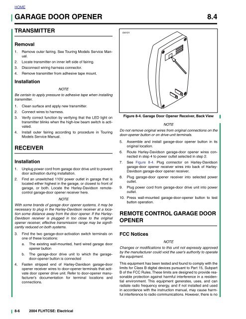
HOMEGARAGE DOOR OPENER 8.4TRANSMITTERRemoval1. Remove outer fairing. See Touring Models Service Manual.2. Locate transmitter on inner left side of fairing.3. Disconnect wiring harness connector.4. Remove transmitter from adhesive tape mount.InstallationNOTEBe certain to apply pressure to adhesive tape when installingtransmitter.1. Clean surface and apply new transmitter.2. Connect wires to harness.3. Verify correct function by verifying that the LED light ontransmitter blinks when the high-low beam switch is activated.4. Install outer fairing according to procedure in TouringModels Service Manual.RECEIVERInstallation1. Unplug power cord from garage door drive unit to preventdoor activation during installation.2. Find an unswitched 110V power outlet in garage that islocated either highest in the garage, or clo<strong>se</strong>st to front ofgarage, or both. Locate the Harley-Davidson remotecontrolgarage-door opener receiver here.NOTEWith some brands of garage door opener systems, it may benecessary to plug in the Harley-Davidson receiver at a locationsome distance away from the door opener. If the Harley-Davidson receiver is plugged in too clo<strong>se</strong> to the originalopener receiver, effective transmission range may be significantlyreduced on both systems.3. Find the two garage-door-activation switch terminals onone of the<strong>se</strong> locations:a. The existing wall-mounted, hard wired garage dooropener buttonb. The garage-door drive unit to which the garagedoor-openerbutton is connected4. Fasten stripped end of Harley-Davidson garage-dooropener receiver wires to door-opener terminals that activatedoor opener drive unit. Refer to door-opener manufacturer’sdocumentation for terminal locations andconnections.i04101Figure 8-4. Garage Door Opener Receiver, Back ViewNOTEDo not remove original wires from original connections on thedoor-opener button or on drive-unit terminals.5. As<strong>se</strong>mble and install garage-door opener button in itsoriginal location.6. Route Harley-Davidson garage-door opener wires connectedin step 4 to power outlet <strong>se</strong>lected in step 2.7. See Figure 8-4. Plug connector on Harley-Davidsongarage-door opener receiver wires into back of Harley-Davidson garage-door opener receiver.8. Plug garage-door opener receiver into <strong>se</strong>lected poweroutlet.9. Plug power cord from garage-door drive unit into poweroutlet.10. Press wall-mounted garage-door-opener button to testbutton operation.REMOTE CONTROL GARAGE DOOROPENERFCC NoticesNOTEChanges or modifications to this unit not expressly approvedby the manufacturer could void the u<strong>se</strong>r’s authority to operatethe equipment.This equipment has been tested and found to comply with thelimits for Class B digital devices pursuant to Part 15, SubpartB of the FCC Rules. The<strong>se</strong> limits are designed to provide reasonableprotection against harmful interference in a residentialenvironment. This equipment generates, u<strong>se</strong>s, and canradiate radio frequency energy, and if not installed and u<strong>se</strong>din accordance with the instruction manual, may cau<strong>se</strong> harmfulinterference to radio communications. However, there is no8-6 2004 FLHTCSE: Electrical