

7.5 clutch release cover - harley-davidson-sweden.se
7.5 clutch release cover - harley-davidson-sweden.se
7.5 clutch release cover - harley-davidson-sweden.se
- No tags were found...

Create successful ePaper yourself
Turn your PDF publications into a flip-book with our unique Google optimized e-Paper software.
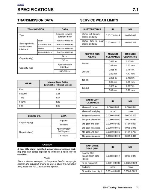
HOMESPECIFICATIONS 7.1TRANSMISSION DATASERVICE WEAR LIMITSTRANSMISSIONDATASHIFTER FORKS IN. MMType5-speed forward -constant meshShifter fork to camgroove end play0.0017-0.0019 0.043-0.048Semi-synthetictransmissionlubricantQuart Part No. 99892-84Ca<strong>se</strong> of Quarts Part No. 98853-96Gallon Part No. 99891-84Shifter fork to geargroove end play0.0010-0.0110 0.025-0.279Capacity (dry)Capacity (wet)Ca<strong>se</strong> of Gallons Part No. 98852-9624 oz.710 mlApproximately20-24 oz.590-710 mlSHIFTER DOGGEARS2nd-5th2nd-3rdMINIMUMCLEARANCEMAXIMUMCLEARANCE0.035 in. 0.139 in.0.89 mm 3.53 mm0.035 in. 0.164 in.0.89 mm 4.17 mmGEARInternal Gear Ratios(Domestic, HDI and Swiss)First 3.21Second 2.211st-4th1st-3rd0.035 in. 0.152 in.0.89 mm 3.86 mm0.035 in. 0.157 in.0.89 mm 3.99 mmThird 1.57Fourth 1.23Fifth 1.00MAINSHAFTTOLERANCEIN.MMMainshaft runout 0.000-0.003 0.000-0.08Capacity (dry)Capacity (wet)ENGINE OILDATA4 quarts3.8 litersApproximately3-1/2 quarts3.3 litersMainshaft end play none none1st gear clearance 0.0000-0.0080 0.000-0.2032nd gear clearance 0.0000-0.0800 0.000-2.0323rd gear end play 0.0050-0.0420 0.127-1.0673rd gear clearance 0.0003-0.0019 0.008-0.0484th gear end play 0.0050-0.0310 0.127-0.7874th gear clearance 0.0003-0.0019 0.008-0.048CAUTIONA bent jiffy stand, modified suspension or uneven parkingarea can cau<strong>se</strong> dipstick to indicate a fal<strong>se</strong> low oilcondition.NOTESince a sidecar equipped motorcycle is fixed in an uprightposition, the actual full engine oil level is about 1/2 inch (12.7mm) above the FULL mark on the dipstick.MAIN DRIVEGEAR (5TH)Bearing fit intransmission ca<strong>se</strong>(loo<strong>se</strong>)IN.MM0.0003-0.0017 0.008-0.043Fit on mainshaft 0.0001-0.0009 0.0025-0.023End play none noneFit in side door (tight) 0.0014-0.0001 0.036-0.00252004 Touring: Transmission 7-1
HOMESERVICE WEAR LIMITS (CONT.’D)COUNTERSHAFTTOLERANCEIN.MMCountershaft runout 0.000-0.003 0.00-0.08Countershaft end play none none1st gear clearance 0.0003-0.0019 0.008-0.0481st gear end play 0.0050-0.0039 0.127-0.0992nd gear clearance 0.0003-0.0019 0.008-0.0482nd gear end play 0.0050-0.0440 0.127-1.1183rd gear clearance 0.0000-0.0080 0.000-0.2034th gear clearance 0.0000-0.0080 0.000-0.2034th gear end play 0.0050-0.0390 0.127-0.9915th gear clearance 0.0000-0.0080 0.000-0.2035th gear end play 0.0050-0.0040 0.127-0.102TORQUE VALUESItem ft/in-lbs NmShifter linkage rodlocknuts80-120 in-lbs 9.0-13.6 NmDetent arm pivot screwto right support block84-108 in-lbs 9.5-12.2 NmShifter cam supportblock screws84-108 in-lbs 9-12 NmTransmission top <strong>cover</strong>socket head screws84-108 in-lbs 9-12 NmNeutral switch 120-180 in-lbs 13.6-20.3 NmClutch <strong>relea<strong>se</strong></strong> <strong>cover</strong>socket head screws120-144 in-lbs 13.6-16.3 NmClutch cable fitting 36-60 in-lbs 4-7 NmTransmission lubricantdrain plug14-21 ft-lbs 19-28 NmTransmission fillerplug/dipstick25-75 in-lbs 2.8-8.5 NmTransmission side door5/16 inch screws1/4 inch screwsMainshaft/countershaftlocknutsTransmission mainshaftsprocket nutTransmission sprocketnut lockplate screws13-16 ft-lbs84-108 in-lbs18-22 Nm9-12 Nm45-55 ft-lbs 61-75 Nm60 ft-lbs, then35° to 45°81 Nm, then35° to 45°90-110 in-lbs 10.2-12.4 NmOil pan bolts 84-108 in-lbs 9-12 NmTransmission-to-enginemounting bolts15 ft-lbs,then30-35 ft-lbs20.3 Nm,then40.7-4<strong>7.5</strong> NmOil ho<strong>se</strong> <strong>cover</strong> 84-108 in-lbs 10-12 NmRear swingarmbracket bolts34-42 ft-lbs 46-57 NmRear swingarmpivot shaft locknut40-45 ft-lbs 54-61 NmShifter lever to shiftershaft socket head screw18-22 ft-lbs 24-30 NmEngine oil drain plug 14-21 ft-lbs 19-28 Nm7-2 2004 Touring: Transmission
HOMETRANSMISSION POWER FLOW 7.2GENERALSee Figure 7-1. The 5-speed transmission consists of twoparallel shafts supporting five gears each. The longer, ormainshaft, also supports the <strong>clutch</strong> and <strong>se</strong>rves as the inputshaft. The shorter shaft is called the countershaft.Each gear on the mainshaft is in constant mesh with a correspondinggear on the countershaft. Each of the<strong>se</strong> five pairsof gears makes up a different speed in the transmission.The transmission gears are divided into two types, gears thatare splined and rotate with the shaft, and freewheeling gearsthat ride on bearings and spin freely on the shaft. A splinedgear always meshes with a freewheeling gear. Also, three ofthe splined gears are able to slide sideways on the shaft.The<strong>se</strong> sliding gears are u<strong>se</strong>d to change transmissionspeeds. The projections (or dogs) on the sides of the slidinggears, engage dogs on adjacent freewheeling gears, transmittingpower through the transmission.4th GearThe shift into fourth is made when mainshaft 2nd is di<strong>se</strong>ngagedfrom mainshaft 3rd and mainshaft 1st engages mainshaft4th, locking it to the mainshaft.5th GearThe shift from fourth to fifth gear occurs when mainshaft 1stis shifted out of mainshaft 4th, and mainshaft 2nd is shifteddirectly into the main drive gear. Mainshaft 2nd lock the maindrive gear to the mainshaft resulting in a direct one-to-onedrive ratio from the <strong>clutch</strong> to the sprocket.Gear shifting is accomplished by three forks which fit intogrooves machined into the hubs of the three sliding gears.The position of the shifter forks is controlled by a drumshapedshifter cam located on the top of the transmission.NeutralPower is introduced to the transmission through the <strong>clutch</strong>. Inneutral, with the <strong>clutch</strong> engaged, the mainshaft 1st and 2ndgears are rotating, but no power is transferred to the countershaftsince countershaft 1st and 2nd are freewheeling gears.1st GearWhen the transmission is shifted into first gear, countershaft3rd, which rotates with the countershaft, engages countershaft1st, which has been spinning freely on the countershaftdriven by mainshaft 1st.Now countershaft 3rd is no longer freewheeling, but locked tothe countershaft causing the countershaft and countershaft5th to turn. Countershaft 5th transmits the power to the maindrive gear and the sprocket.2nd GearSecond gear is engaged when countershaft 3rd is shifted outof countershaft 1st and engages countershaft 2nd. This lockscountershaft 2nd to the countershaft to complete the powerflow as shown.3rd GearTwo shifter forks are u<strong>se</strong>d to make the shift from <strong>se</strong>cond tothird. One fork moves countershaft 3rd out of countershaft2nd to its neutral position, while another fork engages mainshaft2nd with mainshaft 3rd. This locks mainshaft 3rd to themainshaft to complete the power flow as shown.2004 Touring: Transmission 7-3
HOMENeutralOutCountershaft1st GearIn52314Mainshaft523143rd GearOut2nd GearInIn 135 2452 3145th Gear4th GearIn5 23OutOut In1 4 35 2 1 4Sliding MemberPower FlowFigure 7-1. Transmission Power Flow Schematic7-4 2004 Touring: Transmission
HOMESHIFTER LINKAGE 7.3ADJUSTMENT8471If operating problems exist, check the shifter linkage for wear,interference or adjustment. If adjustment is necessary, <strong>se</strong>eSHIFTER LINKAGE below. If problems persist, <strong>se</strong>e thechecks under Section 1.1 TROUBLESHOOTING, TRANS-MISSION, along with the repair procedures in this <strong>se</strong>ction.RodShifter LinkageThe shifter linkage is <strong>se</strong>t at the factory and should not needadjustment under normal circumstances. However, if fullengagement or full lever travel is not achieved, adjust thelinkage rod as follows:LocknutLocknutCAUTIONTo ensure proper gear engagement and avoid possibledamage to transmission, the shifter lever should notcontact the footboard when shifting. A minimum clearanceof 3/8 inch (9.5 mm) between shifter lever and footboardmust be maintained to accommodate enginemovement when running.1. Remove locknut, lockwasher and flat washer to free frontend of shifter rod from shifter lever. See Figure 7-2.Figure 7-2. Shifter Linkage Adjustment2. Loo<strong>se</strong>n locknuts and adjust rod as necessary.3. Install flat washer, lockwasher and locknut to fasten frontend of shifter rod to shifter lever.4. Tighten locknuts to 80-120 in-lbs (9.0-13.6 Nm).2004 Touring: Transmission 7-5
HOMESHIFTER CAM ASSEMBLY/SHIFTER FORKS 7.4DISASSEMBLY1. Remove maxi-fu<strong>se</strong>. See Section 8.3 SYSTEM FUSES,MAXI-FUSE, REMOVAL.2. Remove the exhaust system in two <strong>se</strong>ctions. See Section3.7 REMOVING ENGINE FROM CHASSIS, steps 3-9.3. Remove the magnetic drain plug at the bottom right sideof the oil pan and drain the transmission lubricant into asuitable container. Remove the fill plug/dipstick.4. Using fingers and flat tip screwdriver, remove two elbowconnectors from neutral switch studs. Using 7/8 inch boxend wrench, remove neutral switch and O-ring fromtransmission top <strong>cover</strong>. Remove preformed vent ho<strong>se</strong>from the top <strong>cover</strong> fitting, if necessary.5. Remove the five socket head screws from the transmissiontop <strong>cover</strong>. Remove the top <strong>cover</strong> from the transmissionca<strong>se</strong>. Remove and discard the <strong>cover</strong> gasket.CAUTIONPulling shifter cam as<strong>se</strong>mbly from dowels allows leftsupport block to rotate freely, which can cau<strong>se</strong> screwsand washers to drop into transmission ca<strong>se</strong> if leftloo<strong>se</strong>ly installed.6. See Figure 7-3. Remove the four hex head screws (withflat washers) to free the right and left shifter cam supportblocks. Rai<strong>se</strong> shifter pawl and lift shifter cam as<strong>se</strong>mblyfrom dowels on deck of transmission ca<strong>se</strong>.7. See CLEANING AND INSPECTION, steps 2 and 3, onthe next page. If necessary, disas<strong>se</strong>mble shifter camas<strong>se</strong>mbly as follows:1WARNINGAlways wear proper eye protection when removing retainingrings. U<strong>se</strong> the correct retaining ring pliers. Verifythat the tips of the pliers are not damaged or excessivelyworn. Slippage may propel the ring with enough force tocau<strong>se</strong> eye injury.f1889b7xFlatWasherHex HeadScrewRetainingRingShifter CamSpiralLock RingHex HeadScrewLeftSupport BlockRollerBearingFlatWasherDetentArmSpringRollerBearingPivotScrewRetainingRingRightSupport BlockSpringSleeveFigure 7-3. Shifter Cam As<strong>se</strong>mbly7-6 2004 Touring: Transmission
HOMEInnerRampRetainingRingCableFitting12. Remove the fork shaft from the hole on the right side ofthe transmission ca<strong>se</strong>. See Figure 7-5. Remove theshifter forks from the mainshaft and countershaft geargrooves.13. To replace the transmission gears or side door bearings,<strong>se</strong>e Section 7.6 MAINSHAFT/COUNTERSHAFT. Toreplace the main drive gear, <strong>se</strong>e Section 7.7 MAINDRIVE GEAR.CLEANING AND INSPECTION1WARNINGf1896x7xCouplingClutch CableFigure 7-4. Clutch Relea<strong>se</strong> Cover As<strong>se</strong>mblya. Retract detent arm and slide right support block offend of shifter cam. Remove pivot screw to <strong>relea<strong>se</strong></strong>detent arm, spring sleeve and spring. Remove anddiscard retaining ring. Press against inner race ofroller bearing to remove from support block. Discardroller bearing.b. Moving to opposite side, remove spiral lock ringfrom groove at left end of shifter cam. Using a smallknife, push on end of spiral lock ring working tip ofblade under edge of ring. Rai<strong>se</strong> end of ring until freeof ring groove. Work around circumference of ring toalternately pull spirals from ring groove. Discardring.c. Slide left support block off end of shifter cam.Remove and discard retaining ring. Press againstinner race of roller bearing to remove from supportblock. Discard roller bearing.Compres<strong>se</strong>d air can pierce the skin and cau<strong>se</strong> injury.Never u<strong>se</strong> your hand to check for leaks or to determineair flow rates. Wear safety glas<strong>se</strong>s to shield your eyesfrom flying dirt and debris. Failure to comply could resultin death or <strong>se</strong>rious injury.1. Clean all parts with solvent (except left and right supportblocks if roller bearings installed). Blow dry with lowpressure compres<strong>se</strong>d air.2. Inspect roller bearings. Verify that bearings rotate freelywithout sticking.3. Inspect the shifter cam for cracks or wear. Inspect theends for grooves or pitting. Install new roller bearingswhenever the shifter cam is replaced.4. Check the shifter fork shaft. Replace if bent or damaged.5. Using a small carpenter’s square, verify that the shifterfork shafts are square. If a fork does not rest directly onthe square, then it is bent and must be replaced. SeeFigure 7-6.f1892x7x8. Slide rubber boot off <strong>clutch</strong> cable adjuster. Holding cableadjuster with 1/2 inch wrench, loo<strong>se</strong>n jam nut using 9/16inch wrench. Back jam nut away from cable adjuster.Move adjuster toward jam nut to introduce a largeamount of free play at hand lever.9. Remove six socket head screws to free <strong>clutch</strong> <strong>relea<strong>se</strong></strong><strong>cover</strong> from transmission side door. Remove and discardgasket.10. Remove retaining ring and lift inner ramp out of <strong>clutch</strong><strong>relea<strong>se</strong></strong> <strong>cover</strong>. Turn the inner ramp over so that ball socketsare facing outboard. Remove hook of ramp from buttonon coupling. Remove coupling from <strong>clutch</strong> cable end.See Figure 7-4.11. Unscrew the cable fitting from the <strong>clutch</strong> <strong>relea<strong>se</strong></strong> <strong>cover</strong>.Remove <strong>clutch</strong> cable and fitting.ForkShaftFigure 7-5. Remove Fork Shaft/Shifter Forks(Right Side View)2004 Touring: Transmission 7-7
HOMEf1888x7xASSEMBLYCarpenter’sSquare1. See upper frame of Figure 7-8. Find the shifter fork withthe centered pin. Holding the fork so that the pin is positionedat the rear of the transmission ca<strong>se</strong>, install thefork in the countershaft gear fork groove. See Figure 7-9.ShifterFork2. Slide the two outer forks into the mainshaft gear forkgrooves so that the pins are positioned on the inside (off<strong>se</strong>toutboard). After installation, the pins of all three forksshould be in alignment.SHIFTER FORKS7976PinCenteredMainshaftFork ShaftShifterShaftFigure 7-6. Check Shifter Forks for SquarenessOff<strong>se</strong>tOutboardRightSide123LeftSideCountershaftSHIFTER CAM ASSEMBLY79750.165 in. (4.19 mm)Minimum(2 places on each fork)RightSupport BlockShifterCamLeftSupport Block1. 4th gear shifter fork2. 1st and 2nd gear shifter fork3. 3rd and 5th gear shifter forkf1100bxxFigure 7-7. Shifter Fork Identification6. Inspect the shifter forks for wear. With a micrometer ordial caliper, measure the width of the forks where theycontact the gear fork grooves. Replace any fork thatmeasures less than 0.165 inch (4.19 mm). See Figure 7-7.DetentArmShifterPawl7. Inspect the neutral switch. Depress plunger and ob<strong>se</strong>rvethe action. Plunger should spring back without binding.Switch is non-repairable and must be replaced if defective.See ASSEMBLY, step 11.Figure 7-8. Install Shifter Forks/Shifter Cam7-8 2004 Touring: Transmission
HOME7411b. Lubricate O-ring with clean transmission oil.c. Using 7/8 inch box end wrench, install neutralswitch with O-ring in the transmission top <strong>cover</strong>.Tighten to 120-180 in-lbs (13.6-20.3 Nm).d. Install the two elbow connectors on neutral switchstuds.DetentArmSpring SleeveFigure 7-11. Shifter Cam As<strong>se</strong>mblyPivotScrewSpring6. To ensure proper location, verify that four locating dowelsare in place on the deck of the transmission ca<strong>se</strong>.7. Rai<strong>se</strong> the shifter cam pawl and place the shifter camas<strong>se</strong>mbly over the locating dowels. See Figure 7-12.While aligning the holes in the support blocks with thedowels on the deck of the transmission ca<strong>se</strong>, slide theshifter forks as necessary so that the fork pins engagethe channels in the shifter cam. See lower frame of Figure7-8.8. Hand start the hex head screws (with flat washers) tofasten the right and left support blocks to the transmissionca<strong>se</strong>. Alternately tighten the four support blockscrews to 84-108 in-lbs (9-12 Nm) in a crosswi<strong>se</strong> pattern.NOTECheck the gear engagement and clearance in every gear tomake sure as<strong>se</strong>mbly and alignment is correct.9. Obtain a new top <strong>cover</strong> gasket and align the holes withtho<strong>se</strong> in the transmission ca<strong>se</strong>. Align the holes in the top<strong>cover</strong> with tho<strong>se</strong> in the gasket. Install the five sockethead screws and tighten to 84-108 in-lbs (9-12 Nm).The long screw is installed in the center hole on the leftside of the top <strong>cover</strong>.10. Install preformed vent ho<strong>se</strong> to top <strong>cover</strong> fitting, if removed.NOTEThe neutral switch is not polarity <strong>se</strong>nsitive, so the elbow connectorscan be attached to either stud.12. See Figure 7-4. Install <strong>clutch</strong> cable fitting into <strong>clutch</strong><strong>relea<strong>se</strong></strong> <strong>cover</strong>. Do not tighten at this time.NOTEReplace cable fitting O-ring if damaged or deformed.13. Hold <strong>clutch</strong> cable coupling with button facing outboard.Place cable end in recess of coupling. With ball socketsfacing outboard, place hook of inner ramp on button ofcoupling. Holding inner ramp and coupling together, turnthe as<strong>se</strong>mbly over. Place inner ramp (ball socket sidedown) over balls in outer ramp sockets. Install the retainingring so that the opening is above and to the right ofthe outer ramp tang slot in the <strong>clutch</strong> <strong>relea<strong>se</strong></strong> <strong>cover</strong>.14. Verify that the two locating dowels are in place on thetransmission side door. Hang a new gasket on the dowels.15. Holding <strong>clutch</strong> <strong>relea<strong>se</strong></strong> <strong>cover</strong> in position against transmissionside door, install six socket head screws. Alternatelytighten screws to 120-144 in-lbs (13.6-16.3 Nm)in the <strong>se</strong>quence shown in Figure 7-13.16. Tighten <strong>clutch</strong> cable fitting to 36-60 in-lbs (4-7 Nm).f1891x7xLocatingDowelsNOTEWhenever the transmission top <strong>cover</strong> is removed, be sure toinstall neutral switch after top <strong>cover</strong> installation to ensureproper switch engagement.11. Install the neutral switch in the transmission top <strong>cover</strong> asfollows:a. Roll the vehicle back and forth to verify that thetransmission is in NEUTRAL.Figure 7-12. Place Support Blocks on Locating Dowels7-10 2004 Touring: Transmission
HOMEf1893x7x19. Fill the transmission with 20-24 oz. (590-710 ml) of transmissionlubricant or until the lubricant level on the dipstickof the filler plug is at the F(ULL) mark with the motorcyclein a level, upright position and the filler plug resting on thethreads.315264U<strong>se</strong> only Harley-Davidson SEMI-SYNTHETIC TRANS-MISSION LUBRICANT: Part No.’s 99892-84 (quart),98853-96 (ca<strong>se</strong> of quarts), 99891-84 (gallon), or 98852-96 (ca<strong>se</strong> of gallons).20. Install the transmission filler plug/dipstick in the <strong>clutch</strong><strong>relea<strong>se</strong></strong> <strong>cover</strong>. Tighten the plug to 25-75 in-lbs (2.8-8.5Nm).21. Adjust the <strong>clutch</strong> cable. See Section 6.3 CLUTCH,ADJUSTMENT.Figure 7-13. Clutch Relea<strong>se</strong> Cover Torque Sequence17. Check the O-ring on the transmission lubricant drain plugfor tears, cuts or general deterioration. Replace as necessary.22. Install the exhaust system. See Section 3.8 INSTALL-ING ENGINE IN CHASSIS, steps 46-52.23. Install maxi-fu<strong>se</strong>. See Section 8.3 SYSTEM FUSES,MAXI-FUSE, INSTALLATION.CAUTIONDo not overtighten filler or drain plugs. Overtighteningplugs may cau<strong>se</strong> leaks.18. Install the transmission lubricant drain plug and tightento 14-21 ft-lbs (19-28 Nm).2004 Touring: Transmission 7-11
HOMECLUTCH RELEASE COVER <strong>7.5</strong>REMOVAL/DISASSEMBLY1. Remove maxi-fu<strong>se</strong>. See Section 8.3 SYSTEM FUSES,MAXI-FUSE, REMOVAL.2. Remove the exhaust system in two <strong>se</strong>ctions. See Section3.7 REMOVING ENGINE FROM CHASSIS, steps 3-9.3. Remove the magnetic drain plug at the bottom right sideof the oil pan and drain the transmission lubricant into asuitable container. Remove the filler plug/dipstick.4. Remove six socket head screws to free <strong>clutch</strong> <strong>relea<strong>se</strong></strong><strong>cover</strong> from transmission side door. Depress <strong>clutch</strong> leverto break the <strong>cover</strong> <strong>se</strong>al, and then remove and discardgasket.5. Slide rubber boot off <strong>clutch</strong> cable adjuster. Holding cableadjuster with 1/2 inch wrench, loo<strong>se</strong>n jam nut using 9/16inch wrench. Back jam nut away from cable adjuster.Move adjuster toward jam nut to introduce a largeamount of free play at hand lever.1WARNING7960RampConnectorButtonInnerRampBallSocketClutchRelea<strong>se</strong>CoverTangSlotAlways wear proper eye protection when removing retainingrings. U<strong>se</strong> the correct retaining ring pliers. Verifythat the tips of the pliers are not damaged or excessivelyworn. Slippage may propel the ring with enough force tocau<strong>se</strong> eye injury.6. Remove retaining ring <strong>se</strong>curing ball and ramp mechanismto <strong>clutch</strong> <strong>relea<strong>se</strong></strong> <strong>cover</strong>.7. See Figure 7-14. Lift inner ramp out of <strong>clutch</strong> <strong>relea<strong>se</strong></strong><strong>cover</strong>. Turn the inner ramp over so that ball sockets arefacing outboard. Remove hook of ramp from button oncoupling. Remove coupling from <strong>clutch</strong> cable end.8. Remove balls from outer ramp sockets. Remove outerramp from <strong>clutch</strong> <strong>relea<strong>se</strong></strong> <strong>cover</strong>.9. Unscrew the cable fitting from the <strong>clutch</strong> <strong>relea<strong>se</strong></strong> <strong>cover</strong>.Remove <strong>clutch</strong> cable and fitting.CLEANING AND INSPECTION1. Wash the ball and ramp components in cleaning solvent.2. Inspect the three balls and the ball socket surfaces onboth the inner and outer ramps for wear, pitting, surfacebreakdown and other damage.3. Check fit of the inner ramp hub in the outer ramp.Replace both parts if excessive wear is noted.4. Inspect the inner/outer ramp retaining ring for damage ordistortion.CableEndRecessCouplingBallsFigure 7-14. Clutch Relea<strong>se</strong> Cover As<strong>se</strong>mbly5. See Figure 7-14. Check the recess in the <strong>clutch</strong> <strong>relea<strong>se</strong></strong><strong>cover</strong> casting where the inner and outer ramps areretained. There should be no wear/lips worn into thebore that would catch the ramps and cock them, causingimproper <strong>clutch</strong> adjustment.6. Check <strong>clutch</strong> cable for damage and frayed or worn ends.Check cable fitting O-ring for cuts, tears or signs of deterioration.ASSEMBLY/INSTALLATIONOuterRampTang1. Install <strong>clutch</strong> cable fitting into <strong>clutch</strong> <strong>relea<strong>se</strong></strong> <strong>cover</strong>. Donot tighten cable fitting at this time.NOTEReplace cable fitting O-ring if damaged or deformed.7-12 2004 Touring: Transmission
HOMEOMF5015. Install the exhaust system. See Section 3.8 INSTALL-ING ENGINE IN CHASSIS, steps 46-52.16. Install maxi-fu<strong>se</strong>. See Section 8.3 SYSTEM FUSES,MAXI-FUSE, INSTALLATION.O-RingFigure 7-17. Transmission Lubricant Filler Plug/Dipstick7-14 2004 Touring: Transmission
HOMEABRetaining RingCountershaft 5thCountershaft 2ndSplit CageBearingThrust WasherRetaining RingCountershaft 3rdCDMainshaft 2ndSplit CageBearing RaceRetaining RingThrust WasherMainshaft 3rdThrust WasherRetaining RingESplit CageBearing RaceNOTELeave the mainshaft and countershaft1st and 4th gears installed until theshafts are pres<strong>se</strong>d from the side door.Mainshaft 1stCountershaft 1stMainshaft 4thCountershaft 4thFigure 7-21. Mainshaft/Countershaft Disas<strong>se</strong>mbly2004 Touring: Transmission 7-17
HOME5. See Figure 7-25. Slide the spacers onto the shafts withthe tapered side facing the side door end. Note that themainshaft spacer has a shoulder while the countershaftspacer does not.RetainingRingLocknutBearingCAUTIONFailure to support the inner races while pressing shaftsthrough the side door bearings will result in bearingdamage.6. Place the side door in an arbor press. Support the innerbearing races with a suitable socket. Starting with themainshaft, press the shafts into the bearings. With theshafts properly pres<strong>se</strong>d into the side door, the spacerswill have no end play. Be sure to install the mainshaft tothe left of the fork shaft hole (when viewing the side doorfrom the top).7. Install a spacer and locknut on the threaded end of eachshaft and tighten the nuts until finger tight. See Figure 7-23. Final tightening is performed under INSTALLATION,steps 4 and 5.7969Drill PointFigure 7-23. Side Door Bearings8256MAINSHAFTCOUNTERSHAFTRetaining RingCountershaft 5thMainshaft 2ndCountershaft 2ndSplit Cage BearingRetaining RingThrust WasherThrust WasherRetaining RingThrust WasherRetaining RingMainshaft 3rdSplit Cage BearingMainshaft 1stCountershaft 3rdRetaining RingThrust WasherCountershaft 1stSplit Cage BearingRetaining RingThrust WasherMainshaft 4thSplit Cage BearingCountershaft 4thFigure 7-24. Completed Side Door As<strong>se</strong>mbly2004 Touring: Transmission 7-19
HOMEf1103axx99512 11152025202418221. Side door2. Gasket3. Mainshaft spacer4. Countershaft spacer5. Mainshaft6. Countershaft7. Spacer (2)8. Locknut (2)9. Bearings, one-piecesplit cage (4)10. Mainshaft 4th gear11. Thrust washer (5)12. Retaining ring (6)13. Mainshaft 1st gear14. Countershaft 4th gear15. Retaining ring16. Countershaft 1st gear17. Countershaft 3rd gear18. Mainshaft 3rd gear19. Countershaft 2nd gear20. Thrust washer (2)21. Countershaft 5th gear22. Mainshaft 2nd gear23. Push rod24. Push rod – left side25. Clutch <strong>relea<strong>se</strong></strong> bearing87162917111112 233 101112 13414161112912192112Figure 7-25. Side Door, Mainshaft and Countershaft As<strong>se</strong>mbly (Exploded View)8. See Figure 7-24. Install countershaft 3rd gear with theshifter fork groove facing opposite the side door.9. Install a new retaining ring in the groove just above themainshaft 1st gear. Slide a thrust washer down themainshaft until it contacts the retaining ring. Lightly coata split caged bearing with oil and install in the mainshaftrace next to the thrust washer. Place mainshaft 3rd gearover the bearing. Install a <strong>se</strong>cond thrust washer and anew retaining ring above the gear10. Install a new retaining ring in the groove above the countershaft3rd gear. Slide a thrust washer down the countershaftuntil it contacts the retaining ring. Lightly coat asplit caged bearing with oil and install in the countershaftrace next to the thrust washer. Install the countershaft2nd gear over the bearing with the shifter dogs facingthe side door end of the shaft.11. Slide the countershaft 5th gear down the countershaftuntil it contacts the countershaft 2nd gear. Install a newretaining ring in the groove above the countershaft 5thgear.12. Install the mainshaft 2nd gear on the shaft with theshifter fork groove towards the side door.The final as<strong>se</strong>mbly appears as shown in Figure 7-24.NOTEInstall the main drive gear, if removed. See Section 7.7 MAINDRIVE GEAR, INSTALLATION.7-20 2004 Touring: Transmission
HOMEL = 5/16 InchS = 1/4 Inch5. With the transmission locked, tighten the mainshaft andcountershaft locknuts to 45-55 ft-lbs (61-75 Nm). SeeFigure 7-23.S42S6. Install the oil slinger as<strong>se</strong>mbly (with two-piece push rodand <strong>clutch</strong> <strong>relea<strong>se</strong></strong> bearing components).7. Install shifter cam and fork as<strong>se</strong>mblies. See Section 7.4SHIFTER CAM ASSEMBLY/SHIFTER FORKS,ASSEMBLY.8. Install the bearing inner race on the transmission mainshaft.See Section 6.5 PRIMARY CHAINCASE, MAIN-SHAFT BEARING INNER RACE, INSTALLATION.1LL7969Figure 7-26. Side Door Screw Size and Torque SequenceINSTALLATION5L6L39. Install the starter and oil filler spout. See Section 5.4STARTER, INSTALLATION, steps 1-3 and 5-7.10. Install the primary chainca<strong>se</strong> and starter jackshaftas<strong>se</strong>mbly. Install the <strong>clutch</strong> as<strong>se</strong>mbly, primary chain, andcompensating sprocket components. Install the primarychainca<strong>se</strong> <strong>cover</strong>. See Section 6.5 PRIMARY CHAIN-CASE, INSTALLATION.11. Install the exhaust system. See Section 3.8 INSTALL-ING ENGINE IN CHASSIS, steps 46-52.1. Verify that the two locating dowels are in place on theright side of the transmission ca<strong>se</strong>. Hang a new gasketon the dowels. Install the as<strong>se</strong>mbled side door in thetransmission ca<strong>se</strong>. See Figure 7-19.2. Install the four 5/16 inch screws (with flat washers) tofasten transmission exhaust bracket and bottom of sidedoor to the transmission ca<strong>se</strong>. Install the two 1/4 inchscrews to fasten the top of the side door to the transmissionca<strong>se</strong>. Alternately tighten six screws until snug.3. Re<strong>se</strong>tting the torque wrench as necessary, tighten thefour 5/16 inch screws to 13-16 ft-lbs (18-22 Nm) and thetwo 1/4 inch screws to 84-108 in-lbs (9-12 Nm) in the<strong>se</strong>quence shown in Figure 7-26.4. Lock the transmission. This can be accomplished bymanually engaging the shifter dogs of any two gears(mainshaft or countershaft) with the shifter dogs of anadjacent gear and then turning the mainshaft locknutcounterclockwi<strong>se</strong>.2004 Touring: Transmission 7-21
HOMEMAIN DRIVE GEAR 7.7REMOVAL7970NOTELeave the transmission ca<strong>se</strong> in the frame unless the ca<strong>se</strong>it<strong>se</strong>lf requires replacement. For illustration purpo<strong>se</strong>s, somephotographs may show the ca<strong>se</strong> removed.1. Remove the exhaust system in two <strong>se</strong>ctions. See Section3.7 REMOVING ENGINE FROM CHASSIS, steps 3-9.2. Remove the shifter cam and shifter fork as<strong>se</strong>mblies. SeeSection 7.4 SHIFTER CAM ASSEMBLY/SHIFTERFORKS, DISASSEMBLY.3. Remove the primary chainca<strong>se</strong> <strong>cover</strong>. Remove the<strong>clutch</strong> as<strong>se</strong>mbly, primary chain, and compensatingsprocket components. Remove the starter jackshaftas<strong>se</strong>mbly and primary chainca<strong>se</strong>. See Section 6.5 PRI-MARY CHAINCASE, REMOVAL.RearIndentSideDoor4. Remove oil filler spout and starter. See Section 5.4STARTER, REMOVAL, steps 6-12.5. Remove the bearing inner race from the transmissionmainshaft. See Section 6.5 PRIMARY CHAINCASE,MAINSHAFT BEARING INNER RACE, REMOVAL.6. See Figure 7-27. Remove the six socket head screws(bottom four with flat washers) to free both the side doorand transmission exhaust bracket from the transmissionca<strong>se</strong>. Pull the side door, mainshaft and countershaftfrom the transmission ca<strong>se</strong> as a single as<strong>se</strong>mbly.Remove and discard the door gasket.NOTEDO NOT USE A HAMMER TO REMOVE THE SIDE DOOR.If the side door sticks or binds on the locating dowels, gentlypry open using the indents at each side of the door. See Figure7-27.7. Remove the two socket screws and lockplate to free thesprocket nut. Remove the sprocket nut. U<strong>se</strong> an airimpact wrench for best results.NOTEThe transmission sprocket nut has left handed threads. Turnthe nut clockwi<strong>se</strong> to remove from the main drive gear.8. Moving to rear wheel, remove E-clip and loo<strong>se</strong>n hex nuton right side of axle. Moving to left side, turn adjustercam in a counterclockwi<strong>se</strong> direction until belt tension isrelieved. Remove the belt from the transmissionsprocket.9. Remove the transmission sprocket, spacer sleeve, mainshaftoil <strong>se</strong>al and quad <strong>se</strong>al.Figure 7-27. Remove Transmission Side Door1WARNINGAlways wear proper eye protection when removing retainingrings. U<strong>se</strong> the correct retaining ring pliers. Verifythat the tips of the pliers are not damaged or excessivelyworn. Slippage may propel the ring with enough force tocau<strong>se</strong> eye injury.10. Remove the retaining ring from the roller bearing bore.11. Pull the main drive gear using HD-35316B, MAIN DRIVEGEAR REMOVER AND INSTALLER. See instructionsprovided with the tool.12. Using a block of wood and a hammer, remove the rollerbearing from the transmission ca<strong>se</strong>. Discard the bearing.NOTEAlways replace the main drive gear bearing when the maindrive gear is removed. The bearing will be damaged duringthe removal procedure.CLEANING AND INSPECTION1. Clean all parts in solvent except the transmission ca<strong>se</strong>and needle bearings. Blow dry with compres<strong>se</strong>d air.7-22 2004 Touring: Transmission
HOMEFigure 7-31. Main Drive Gear Large Oil Seal Installer(Part No. HD-41496)Figure 7-33. Final Drive Sprocket Locking Tool(Part No. HD-41184)f2273x7xTransmissionSprocketTransmissionCa<strong>se</strong>Right Side ViewMain DriveGearMainshaftOil SealSpacerSleeveSprocketNutf1172a6xLockplateSprocketLocking Toolf1855x7xPivot Shaftf1856x7xQuad SealTransmissionSprocketLubricateContact SurfacesSocketScrewFigure 7-32. Install Transmission Sprocket ComponentsINSTALLATION1. Install new main drive gear bearing using the MAINDRIVE GEAR REMOVER/INSTALLER (Part No. HD-35316B). To prevent damage, always apply force to thebearing outer race during installation. Install a newretaining ring with the beveled side out and the 90°opening facing the rear. See in<strong>se</strong>t of Figure 7-32. Installthe main drive gear in the transmission ca<strong>se</strong> using thespecial tool.2. Verify that the two locating dowels are in place on theright side of the transmission ca<strong>se</strong>. Hang a new gasketon the dowels. In<strong>se</strong>rting the mainshaft through the mainSprocketNutSprocketLocking ToolFigure 7-34. Install Final Drive Sprocket Locking Tooldrive gear, place the side door against the ca<strong>se</strong>. Tightenthe 5/16 inch mounting screws to 13-16 ft-lbs (18-22Nm). Tighten the 1/4 inch screw to 84-108 in-lbs (9-12Nm).7-24 2004 Touring: Transmission
HOME3. With the garter spring side out (toward the transmissionca<strong>se</strong>), place a new <strong>se</strong>al on lip of MAIN DRIVE GEARLARGE OIL SEAL INSTALLER (Part No. HD-41496).See Figure 7-31. Slide the tool over the mainshaft sothat it is positioned squarely over the bearing bore in thetransmission housing. Hand press the <strong>se</strong>al into the bore;a rubber mallet may be u<strong>se</strong>d to lightly tap the driver, ifnecessary. Install the quad <strong>se</strong>al. See Figure 7-32.4. Apply a small amount of the appropriate H-D transmissionlubricant to outside diameter of spacer sleeve.5. Install spacer sleeve on the main drive gear with chamferfacing inboard. Install the transmission sprocket.Install the belt on the sprocket as the sprocket isinstalled on the main drive gear.WrenchPilotFigure 7-35. Mainshaft Locknut Wrench/Pilot(Part No. HD-94660-37B )6. Install the sprocket nut. The procedure is ba<strong>se</strong>d onwhether a new or u<strong>se</strong>d nut is being installed.CAUTIONExerci<strong>se</strong> caution to avoid getting oil on the threads ofthe sprocket nut or the integrity of the lock patch may becompromi<strong>se</strong>d.New sprocket nut: smear a small quantity of cleanengine oil on the inside face of both the sprocket nut andthe sprocket. Limit the application to where the surfacesof the two parts contact each other. Install the sprocketnut until finger tight.NOTEThe transmission sprocket nut has left handed threads. Turnthe nut counterclockwi<strong>se</strong> to install on the main drive gear.SprocketNutPilotf1857x7xU<strong>se</strong>d sprocket nut: apply Loctite 262 (red) to thethreads of the sprocket nut. Also smear a small quantityof Loctite or clean engine oil on the inside face of boththe sprocket nut and the sprocket. Limit the applicationto where the surfaces of the two parts contact eachother. Install the sprocket nut until finger tight.7. Lock transmission sprocket with FINAL DRIVESPROCKET LOCKING TOOL, Part No. HD-41184. SeeFigure 7-33. In<strong>se</strong>rt handle of tool below pivot shaftinboard of bottom frame tube and attach to sprocket.Snug thumbscrew to lock position of tool on sprocket.See Figure 7-34.MainshaftLocknutWrenchf1858x7x8. Install pilot of MAINSHAFT LOCKNUT WRENCH (PartNo. HD-94660-37B) on threaded end of mainshaft. SeeFigure 7-35. Slide sleeve of locknut wrench over pilotand onto sprocket nut. Tighten sprocket nut to 60 ft-lbs(81 Nm). As the nut is tightened the handle of thesprocket locking tool ri<strong>se</strong>s to contact the pivot shaft,thereby preventing sprocket/mainshaft rotation. See Figure7-36.9. Scribe a straight line on the transmission sprocket nutcontinuing the line over onto the transmission sprocketas shown in Figure 7-37. Tighten the transmissionsprocket nut an additional 35° to 40°.TorqueWrenchFigure 7-36. Install Mainshaft Locknut Pilot/Wrenchand Torque Sprocket Nut10. Install lockplate over nut so that two diagonally oppositeholes align with two tapped holes in sprocket. To find thebest fit, lockplate can be rotated to a number of positionsand can be placed with either side facing sprocket.2004 Touring: Transmission 7-25
HOMESprocket Nutf1977x6xSeal ProtectorSleeveDriver45°TransmissionSprocket35°Scribe Lineon Nut and SprocketFigure 7-38. Main Drive Gear Seal Installer(Part No. HD-41405 )f1853x7xFigure 7-37. Tighten/Secure Sprocket NutOil Seal11. If holes in lockplate do not align with tho<strong>se</strong> in sprocket,tighten sprocket nut as necessary (up to the 45° maximum)until sprocket and lockplate holes are in alignment.See Figure 7-37.CAUTIONMaximum allowable tightening of sprocket nut is 45° ofcounterclockwi<strong>se</strong> rotation after a torque of 60 ft-lbs (81Nm). Do not loo<strong>se</strong>n sprocket nut when attempting toalign holes.Seal ProtectorSleeveFigure 7-39. Slide Protector Sleeve/Oil Seal on Mainshaft12. In<strong>se</strong>rt two socket head screws through lockplate intosprocket holes. Tighten screws to 90-110 in-lbs.NOTEThe socket head screws have a thread locking compoundthat allows them to be reu<strong>se</strong>d up to three times. The fourthtime the screws are removed, replace with new screws (H-DPart No. 3594).13. Adjust the belt tension and complete installation of rearwheel. See Section 6.4 SECONDARY DRIVE BELTAND SPROCKETS, ADJUSTMENT, steps 6-10.SealDriverf1854x7x14. If the main drive gear oil <strong>se</strong>al was not installed with theneedle bearings (or if a faulty <strong>se</strong>al is dis<strong>cover</strong>ed with themain drive gear installed in the transmission ca<strong>se</strong>), analternative method is provided using the MAIN DRIVEGEAR SEAL INSTALLER, HD-41405. See Figure 7-38.NOTEIf a <strong>se</strong>rviceable <strong>se</strong>al is already installed, proceed to step 15.To install the oil <strong>se</strong>al with the main drive gear in thetransmission ca<strong>se</strong>, proceed as follows:a. Verify that the garter spring is in place on the lip ofthe oil <strong>se</strong>al.Figure 7-40. Install Oil Seal Using Driverb. Place the <strong>se</strong>al protector sleeve over the end of themainshaft. Lightly lubricate the protector sleeve and<strong>se</strong>al ID with clean transmission oil.c. Squarely <strong>se</strong>at the oil <strong>se</strong>al on the <strong>se</strong>al protectorsleeve with the garter spring facing the transmissionca<strong>se</strong>. See Figure 7-39.7-26 2004 Touring: Transmission
HOMEd. Using the <strong>se</strong>al driver, hand press the <strong>se</strong>al onto themainshaft. A rubber mallet may be u<strong>se</strong>d to lightlytap the driver, if necessary.15. Install the bearing inner race on the transmission mainshaft.See Section 6.5 PRIMARY CHAINCASE, MAIN-SHAFT BEARING INNER RACE, INSTALLATION.16. Install shifter cam and fork as<strong>se</strong>mblies. See Section 7.4SHIFTER CAM ASSEMBLY/SHIFTER FORKS,ASSEMBLY.17. Install the starter and oil filler spout. See Section 5.4STARTER, INSTALLATION, steps 1-3 and 5-7.18. Install the primary chainca<strong>se</strong> and starter jackshaftas<strong>se</strong>mbly. Install the <strong>clutch</strong> as<strong>se</strong>mbly, primary chain, andcompensating sprocket components. Install the primarychainca<strong>se</strong> <strong>cover</strong>. See Section 6.5 PRIMARY CHAIN-CASE, INSTALLATION.19. Install the exhaust system. See Section 3.8 INSTALL-ING ENGINE IN CHASSIS, steps 46-52.Countershaft Needle BearingReplacement1. Find a suitable bearing driver 1-1/4 inch (31.75 mm) indiameter.2. From the outside of the transmission ca<strong>se</strong> place the needlebearing open end first next to the bearing bore. Holdthe driver squarely against the clo<strong>se</strong>d end of the bearingand tap the bearing into place. The bearing is properlypositioned when it is driven inward flush with the outsidesurface of the ca<strong>se</strong> or to a maximum depth of 0.030 inch(0.76 mm).3. Lubricate the bearing with TransLube.2004 Touring: Transmission 7-27
HOMETRANSMISSION CASE/OIL PAN 7.8GENERALThe transmission ca<strong>se</strong> and oil pan can be removed as anas<strong>se</strong>mbly if the transmission ca<strong>se</strong> must be replaced.If necessary, the oil pan can be removed without removingthe transmission ca<strong>se</strong>. Once the rear wheel is removed, theoil pan can be slid out from the rear.REMOVALTransmission Ca<strong>se</strong> and Oil Pan1. See Figure 7-41. Remove both the engine oil and transmissionlubricant drain plugs from the oil pan. Drain thefluids into suitable containers.2. Remove the mainshaft and countershaft as<strong>se</strong>mblies.See Section 7.6 MAINSHAFT/COUNTERSHAFT,REMOVAL.f2267x7x13126549107531185171261819201514161. Screw2. Screw3. Oil ho<strong>se</strong> <strong>cover</strong>4. Oil ho<strong>se</strong> (2)5. Ho<strong>se</strong> clamp (6)6. Straight fitting (3)7. Crankca<strong>se</strong>breather ho<strong>se</strong>8. Screw (4)9. Oil filler cap/dipstick10. Oil filler spout11. Filler spout gasket12. Transmissionhousing13. Dowel pin14. Bolt (4)15. Washer (4)16. Ring dowel17. Baffle spring18. Serpentine baffle19. Oil pan gasket20. Oil pan21. O-ring (2)22. Magnetic plug (2)23. Pipe plug24. Screw (12)2421TransmissionDrain Plug21232222Engine OilDrain PlugFigure 7-41. Transmission Ca<strong>se</strong> and Oil Pan7-28 2004 Touring: Transmission
HOME7968WasherRetainingRingSplinedShifter ShaftCenteringScrew7. Using a side cutters, cut and remove clamps on transmissionside of oil supply and return ho<strong>se</strong>s. Pull ho<strong>se</strong>sfrom fittings on transmission housing.8. Cut and remove clamp on transmission side of crankca<strong>se</strong>breather ho<strong>se</strong>. Pull ho<strong>se</strong> from fitting on oil fillerspout.9. Remove four bolts (with flat washers) to free front oftransmission from rear of crankca<strong>se</strong>. Loo<strong>se</strong>n andremove bolts in a crosswi<strong>se</strong> pattern. Move transmissionrearward until two ring dowels in lower flange are free ofcrankca<strong>se</strong>.NOTEIf the main drive gear was not removed from the transmissionca<strong>se</strong>, then it may be removed at this time. See Section 7.7MAIN DRIVE GEAR, REMOVAL.Figure 7-42. Shifter Pawl Centering Screw10. Remove the transmission ca<strong>se</strong> from the right side of thevehicle.ShifterLever SpringShifterPawlSlotNOTEIf removal is difficult, remove the twelve socket head bolts to<strong>se</strong>parate the oil pan from the transmission ca<strong>se</strong>. For bestresults, u<strong>se</strong> a long 3/16 inch ball hex socket driver. Holes inthe lower frame crossmember allow access to bolts whichwould not otherwi<strong>se</strong> be accessible.CenteringSpring7967Figure 7-43. Shifter Pawl As<strong>se</strong>mblySplinedShifter ShaftOil Pan OnlyNOTEPerform the following procedure if only the oil pan must beremoved.1. See Figure 7-44. Remove both the engine oil and transmissionlubricant drain plugs from the oil pan. Drain thefluids into suitable containers.3. Remove rear wheel and rear swingarm. See Section2.20 REAR SWINGARM, REMOVAL.NOTEThe main drive gear and bearing may be removed with thetransmission ca<strong>se</strong> in the frame. See Section 7.7 MAINDRIVE GEAR, REMOVAL.711932f1677x3xLEFTSIDE4. Remove the socket screw from the shifter lever. Removethe lever from the splined end of the shifter shaft. Marksplines on shaft and lever as they are removed to assistin as<strong>se</strong>mbly. See Figure 7-42.5685. Using a T50 TORX drive head, turn the centering screwout until it clears the centering spring slot of the shifterpawl as<strong>se</strong>mbly. Remove the retaining ring and flatwasher from the splined end of the shifter shaft. See Figure7-43. Push on end of shaft to free shifter pawlas<strong>se</strong>mbly from transmission ca<strong>se</strong>.6. Remove two allen head socket screws to <strong>relea<strong>se</strong></strong> oilho<strong>se</strong> <strong>cover</strong>. See Figure 7-41.RIGHTSIDE14TransmissionDrain PlugFigure 7-44. Oil Pan Torque Sequence1012Engine OilDrain Plug2004 Touring: Transmission 7-29
HOME2. Install lifting strap around frame backbone, and usingoverhead jack, support vehicle from the top.3. Remove rear wheel. See Section 2.4 REAR WHEEL,REMOVAL.4. With a long 3/16 inch ball hex socket driver (Snap-Onstock number FABL6 or equal), remove the twelvesocket head bolts from the bottom of the oil pan.NOTEHoles in the frame crossmember allow access to bolts whichwould not otherwi<strong>se</strong> be accessible.CAUTIONRemove the engine oil dipstick before attempting toslide the oil pan rearward. Contact with the oil pan willresult in damage to the dipstick.5. Slide oil pan rearward and remove from underside oftransmission.CLEANING AND INSPECTION1. Clean all parts in solvent except the transmission ca<strong>se</strong>and needle bearings. Blow dry with compres<strong>se</strong>d air.CAUTIONThe transmission ca<strong>se</strong> and needle bearings must not becleaned. Normal cleaning methods will wash dirt or othercontaminants into the bearing ca<strong>se</strong> (behind the needles)and lead to bearing failure.2. Inspect the shifter pawl and centering spring for wear.Replace lever as<strong>se</strong>mbly if pawl ends are damaged.Replace centering spring if elongated.3. Inspect the shifter lever spring. Replace the spring if itfails to hold the pawl on the cam pins.4. Thoroughly clean the oil pan with solvent, if removed.5. Inspect the ho<strong>se</strong>s for nicks, cuts or general deterioration.Replace as necessary. U<strong>se</strong>d compres<strong>se</strong>d air to verifythat ho<strong>se</strong>s and fittings are unobstructed.INSTALLATIONOil Pan OnlyNOTEThe following procedure describes installation of the oil panwith the transmission ca<strong>se</strong> mounted in the motorcycle frame.Follow the applicable steps to install the oil pan with thetransmission ca<strong>se</strong> removed from the motorcycle frame.1. Coat gasket surface of oil pan with a thin coat of HYLO-MAR® gasket <strong>se</strong>aler.2. Place gasket on oil pan and allow <strong>se</strong>aler to dry untiltacky.3. It is normal for the baffle springs to hold the oil pan awayfrom transmission housing. U<strong>se</strong> a long screwdriver tocompress the springs as the pan enters the housing.Exerci<strong>se</strong> caution to avoid cocking or distorting thesprings.4. Position oil pan under transmission and install the twelveoil pan bolts, but only tighten about two turns after initialthread engagement.CAUTIONInspect the oil pan gasket to ensure that gasket is properlypositioned. If gasket was moved out of position,remove bolts and repeat step 3 to ensure that gasket isproperly positioned.5. Tighten the oil pan bolts to 84-108 in-lbs (9-12 Nm) followingthe numerical <strong>se</strong>quence shown in Figure 7-44.6. Install rear wheel. See Section 2.4 REAR WHEEL,INSTALLATION.7. Remove lifting strap to <strong>relea<strong>se</strong></strong> frame backbone fromoverhead jack.Transmission Ca<strong>se</strong> and Oil PanNOTEIf the main drive gear was as<strong>se</strong>mbled prior to mounting of thetransmission, place belt on transmission sprocket as transmissionis placed in position.1. From right side of vehicle, place the transmission ca<strong>se</strong>(with oil pan) in the motorcycle frame. Move transmissionforward until two ring dowels in lower flange fullyengage holes in crankca<strong>se</strong>. Support the engine andtransmission, so that they do not sag at their mating surfaces.2. Install the transmission-to-engine mounting bolts as follows:a. Using a crosswi<strong>se</strong> pattern, hand tighten four bolts(with flat washers) to <strong>se</strong>cure transmission housingto rear of crankca<strong>se</strong>.b. Alternately tighten the four bolts to 15 ft-lbs (20.3Nm) in the same crosswi<strong>se</strong> pattern.NOTEFor best results, u<strong>se</strong> Open End Crowfoot (Snap-On FC018)on upper left and upper right transmission housing tocrankca<strong>se</strong> bolts.c. Repeating the pattern again, final tighten the fourbolts to 30-35 ft-lbs (40.7-4<strong>7.5</strong> Nm).3. Slide new clamps onto free ends of oil supply and returnho<strong>se</strong>s. See Figure 7-41. Install ho<strong>se</strong>s onto transmissionfittings. Crimp clamps using the Ho<strong>se</strong> Clamp Pliers (HD-41137).7-30 2004 Touring: Transmission
HOMEf1894x7x10. Install the primary chainca<strong>se</strong> and starter jackshaftas<strong>se</strong>mbly. Install <strong>clutch</strong> as<strong>se</strong>mbly, primary chain, andcompensating sprocket components. Install the primarychainca<strong>se</strong> <strong>cover</strong>. See Section 6.5 PRIMARY CHAIN-CASE, INSTALLATION.11. Install rear swingarm and rear wheel. Adjust belt tension.See Section 2.20 REAR SWINGARM, INSTALLA-TION.12. Install engine oil drain plug and tighten to 14-21 ft-lbs(19-28 Nm).13. Add engine oil. See Section 3.3 GENERAL INFORMA-TION, CHANGING ENGINE OIL AND FILTER, steps 9-12.Figure 7-45. Shifter Pawl As<strong>se</strong>mbly4. Slide new clamp onto free end of crankca<strong>se</strong> breatherho<strong>se</strong>. Install ho<strong>se</strong> onto fitting of oil filler spout. Crimpclamp using HOSE CLAMP PLIERS (HD-97087-65B).5. Install two allen head socket screws (with captive washers)to <strong>se</strong>cure oil ho<strong>se</strong> <strong>cover</strong> to transmission and enginehousings. Longer screw goes to engine housing. Alternatelytighten screws to 84-108 in-lbs (10-12 Nm).6. Slide splined end of shifter shaft through sleeved boreuntil it protrudes from left side of ca<strong>se</strong>. Install flat washerand retaining ring on splined end of shaft. Hold theshifter pawl as<strong>se</strong>mbly inside the transmission ca<strong>se</strong> sothat the centering spring slot is aligned with the centeringscrew. Using a T50 TORX drive head, tighten centeringscrew until snug. See Figure 7-45.7. Install the shifter lever onto the splined end of the shiftershaft taking note to align marks placed on splines duringdisas<strong>se</strong>mbly. Install socket head screw and tighten to18-22 ft-lbs (24-30 Nm). Make sure screw registers inslot of shifter lever.8. Install the mainshaft and countershaft as<strong>se</strong>mblies. SeeSection 7.6 MAINSHAFT/COUNTERSHAFT, INSTAL-LATION.9. Install belt on transmission sprocket.2004 Touring: Transmission 7-31
HOMENOTES7-32 2004 Touring: Transmission


