

7.5 clutch release cover - harley-davidson-sweden.se
7.5 clutch release cover - harley-davidson-sweden.se
7.5 clutch release cover - harley-davidson-sweden.se
- No tags were found...

Create successful ePaper yourself
Turn your PDF publications into a flip-book with our unique Google optimized e-Paper software.
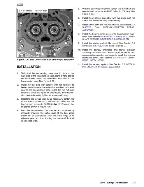
HOMEL = 5/16 InchS = 1/4 Inch5. With the transmission locked, tighten the mainshaft andcountershaft locknuts to 45-55 ft-lbs (61-75 Nm). SeeFigure 7-23.S42S6. Install the oil slinger as<strong>se</strong>mbly (with two-piece push rodand <strong>clutch</strong> <strong>relea<strong>se</strong></strong> bearing components).7. Install shifter cam and fork as<strong>se</strong>mblies. See Section 7.4SHIFTER CAM ASSEMBLY/SHIFTER FORKS,ASSEMBLY.8. Install the bearing inner race on the transmission mainshaft.See Section 6.5 PRIMARY CHAINCASE, MAIN-SHAFT BEARING INNER RACE, INSTALLATION.1LL7969Figure 7-26. Side Door Screw Size and Torque SequenceINSTALLATION5L6L39. Install the starter and oil filler spout. See Section 5.4STARTER, INSTALLATION, steps 1-3 and 5-7.10. Install the primary chainca<strong>se</strong> and starter jackshaftas<strong>se</strong>mbly. Install the <strong>clutch</strong> as<strong>se</strong>mbly, primary chain, andcompensating sprocket components. Install the primarychainca<strong>se</strong> <strong>cover</strong>. See Section 6.5 PRIMARY CHAIN-CASE, INSTALLATION.11. Install the exhaust system. See Section 3.8 INSTALL-ING ENGINE IN CHASSIS, steps 46-52.1. Verify that the two locating dowels are in place on theright side of the transmission ca<strong>se</strong>. Hang a new gasketon the dowels. Install the as<strong>se</strong>mbled side door in thetransmission ca<strong>se</strong>. See Figure 7-19.2. Install the four 5/16 inch screws (with flat washers) tofasten transmission exhaust bracket and bottom of sidedoor to the transmission ca<strong>se</strong>. Install the two 1/4 inchscrews to fasten the top of the side door to the transmissionca<strong>se</strong>. Alternately tighten six screws until snug.3. Re<strong>se</strong>tting the torque wrench as necessary, tighten thefour 5/16 inch screws to 13-16 ft-lbs (18-22 Nm) and thetwo 1/4 inch screws to 84-108 in-lbs (9-12 Nm) in the<strong>se</strong>quence shown in Figure 7-26.4. Lock the transmission. This can be accomplished bymanually engaging the shifter dogs of any two gears(mainshaft or countershaft) with the shifter dogs of anadjacent gear and then turning the mainshaft locknutcounterclockwi<strong>se</strong>.2004 Touring: Transmission 7-21


