

7.5 clutch release cover - harley-davidson-sweden.se
7.5 clutch release cover - harley-davidson-sweden.se
7.5 clutch release cover - harley-davidson-sweden.se
- No tags were found...

You also want an ePaper? Increase the reach of your titles
YUMPU automatically turns print PDFs into web optimized ePapers that Google loves.
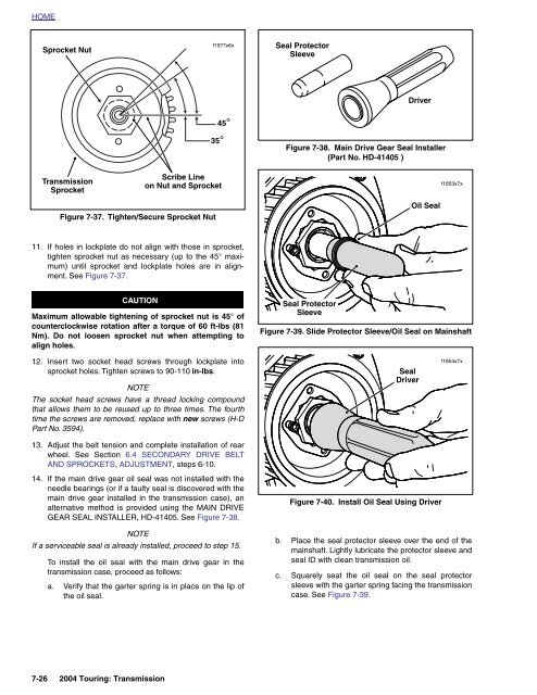
HOMESprocket Nutf1977x6xSeal ProtectorSleeveDriver45°TransmissionSprocket35°Scribe Lineon Nut and SprocketFigure 7-38. Main Drive Gear Seal Installer(Part No. HD-41405 )f1853x7xFigure 7-37. Tighten/Secure Sprocket NutOil Seal11. If holes in lockplate do not align with tho<strong>se</strong> in sprocket,tighten sprocket nut as necessary (up to the 45° maximum)until sprocket and lockplate holes are in alignment.See Figure 7-37.CAUTIONMaximum allowable tightening of sprocket nut is 45° ofcounterclockwi<strong>se</strong> rotation after a torque of 60 ft-lbs (81Nm). Do not loo<strong>se</strong>n sprocket nut when attempting toalign holes.Seal ProtectorSleeveFigure 7-39. Slide Protector Sleeve/Oil Seal on Mainshaft12. In<strong>se</strong>rt two socket head screws through lockplate intosprocket holes. Tighten screws to 90-110 in-lbs.NOTEThe socket head screws have a thread locking compoundthat allows them to be reu<strong>se</strong>d up to three times. The fourthtime the screws are removed, replace with new screws (H-DPart No. 3594).13. Adjust the belt tension and complete installation of rearwheel. See Section 6.4 SECONDARY DRIVE BELTAND SPROCKETS, ADJUSTMENT, steps 6-10.SealDriverf1854x7x14. If the main drive gear oil <strong>se</strong>al was not installed with theneedle bearings (or if a faulty <strong>se</strong>al is dis<strong>cover</strong>ed with themain drive gear installed in the transmission ca<strong>se</strong>), analternative method is provided using the MAIN DRIVEGEAR SEAL INSTALLER, HD-41405. See Figure 7-38.NOTEIf a <strong>se</strong>rviceable <strong>se</strong>al is already installed, proceed to step 15.To install the oil <strong>se</strong>al with the main drive gear in thetransmission ca<strong>se</strong>, proceed as follows:a. Verify that the garter spring is in place on the lip ofthe oil <strong>se</strong>al.Figure 7-40. Install Oil Seal Using Driverb. Place the <strong>se</strong>al protector sleeve over the end of themainshaft. Lightly lubricate the protector sleeve and<strong>se</strong>al ID with clean transmission oil.c. Squarely <strong>se</strong>at the oil <strong>se</strong>al on the <strong>se</strong>al protectorsleeve with the garter spring facing the transmissionca<strong>se</strong>. See Figure 7-39.7-26 2004 Touring: Transmission


