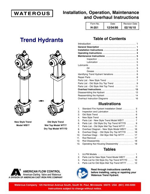
Trend Hydrants
Trend Hydrants
Trend Hydrants
- No tags were found...

Create successful ePaper yourself
Turn your PDF publications into a flip-book with our unique Google optimized e-Paper software.
Installation InstructionsThe ideal location for a hydrant to be installed is onethat is well drained and provides a firm support for thehydrant. In regions where freezing occurs, the hydrantbottom should always be below the frost line. If thehydrant is installed properly it will not freeze, break orheave. A typical installation is shown in Figure 1 onpage 3.Where there is a high ground water level or otherconditions which prevent the use of hydrants withdrains, ``no-drain” hydrants must be used. These hydrantsare available in two versions:(a) No drain valve and no drain openings in bottom.(b) With drain valve, but drain holes in bottom areplugged with brass pipe plugs and reducing bushings.Both version (a) and version (b) hydrants are identifiedwith an aluminum tag which is marked “No-drain”“Pump after use.”Version (b) can easily be converted to a self-draininghydrant before installation by removing the brass pipeplugs. The “No-drain” tag should also be removed.NOTE: “No-drain” hydrants should be identifiedand pumped after each use regardless of weatherconditions and must be pumped if temperaturesbelow freezing are likely. A ``no-drain” hydrantshould be checked often to make sure the barrelstays dry.To convert a standard hydrant to a no-drain hydrant,a ``no-drain” valve seat is available. Valve seat wouldbe changed and drain plunger (27) would be eliminated.Refer to “Overhaul Instructions” section of thismanual for details for the removal and installation ofinternal components.While the details of hydrant installation vary with theterrain in which a hydrant is to be installed, the followinggeneral instructions will usually apply.1. Tighten all standpipe and inlet flange bolts andnuts.2. Make sure the hydrant inlet and main lateral pipeare clean and free of all foreign matter. Removeall contaminants that may affect water systempurity before connecting the joint.3. The installation of an auxiliary (hydrant shut-off)valve in the hydrant lateral pipe is recommended(see the Valve Installation Guide).NOTE: Use 1/8” thick rubber “ring” type gasketsor Toruseal full face gaskets. Do not usecomposition or flat full face gaskets.!WARNINGWater hammer and high pressure. Can causepersonal injury, major damage to the hydrant,water main, hose or attached equipment.Only screw type gate valves, requiring a minimumof eight full turns to open or close, should be usedon fire hydrants. Rapid opening or closing ofhydrant valves can cause water hammer and highpressure. AFC series 2500 ductile iron resilientwedge valves are recommended.4. Support hydrant on a flat stone or cement block.Check hydrant to make sure it is plumb. Usestandpipe for vertical alignment.5. Restrain hydrant movement with appropriatethrust blocking or approved mechanical strappingmethod to prevent pipe joint separation.6. Check drain holes in hydrant inlet to make surethey are clear.7. Provide a drain area around the hydrant inlet to alevel several inches above the drain holes usingclean, washed stones or coarse gravel. Materialshould not be smaller than the drain hole diameteror larger than egg size.8. Cover drainage stones with polyethylene (4-6 milthick) or a similar waterproof material to preventdirt from clogging the drainage area.9. Backfill over pipe only. Leave the complete hydrantexposed to check for leaks at the inlet jointduring testing.10. Turn on water main valve fully, open hydrant valvefully and flush at full flow for several minutes untilwater becomes clear. If hydrant is not flushedthoroughly after installation, sand or other foreignmatter left in water main or hydrant during installationmay become imbedded in main valve andeventually cause leakage.H-351 Page 2 of 18
Figure 1 . Standard Fire Hydrant Installation DetailH-351 Page 3 of 18
Operating InstructionsAlways open a hydrant completely, never just partway. Unless the hydrant is open far enough, the drainvalve will be partially open, and water gushing out ofthe drain ports may wash away the soil around thehydrant bottom. Also, a partially closed hydrant maytrap small stones and other debris between the hydrantvalve and seat.!WARNINGHydrant cap hazard.Can result in serious injury.Make sure the hydrant is not charged when removingcaps. If the hydrant is charged, the cap willblow off.If hydrant does not shut off completely, do not attemptto force it. Stones or other foreign matter between themain valve rubber (32) and valve seat (29) may preventthe valve from closing. Partially opening andclosing valve several times may dislodge obstructionbetween valve and seat.If this does not work, remove operating rod assemblyas described in the “Overhaul Instructions” section ofthis manual. Also remove the obstruction, replacingthe main valve rubber if it has been damaged.Since a Waterous hydrant will open and close easily ifmaintained properly, extra long operating wrenchesshould not be used.Each time hydrant is shut off, back off operating nutslightly to relieve tension on operating rod. Sincewater pressure will hold valve up against its seat,turning operating nut to a dead stop is not necessaryif valve and seat are in good condition.NOTE: If the main valve rubber or seat have beendamaged, it may be necessary to apply extratorque to achieve shut-off. If this condition exits,the hydrant should be repaired as soon as possible.H-351 Page 4 of 18
Maintenance InstructionsThe ease of operation and the frequency of repairsdepends on the condition of the water system and themaintenance given. Dirt, gravel and other foreign materialin the water system may prevent the hydrantfrom closing or draining properly, or may damage themain valve. Under most operating conditions, the followingrecommended semi-annual lubrication andinspection is the only maintenance required.Inspection1. Every spring and fall, open hydrant completelyand let water run for several minutes. Open andclose valve to make sure it works properly, andcheck for leaks.2. After the valve is closed, the water in the hydrantshould drain rapidly. If it does not, the drain portsmay be clogged. To clear drain ports, installnozzle cap, and tighten until water tight, thenopen hydrant two or three turns for several minutes.This will leave drain port partially open andpermit water pressure to wash out the obstruction.If this method is unsuccessful, remove the operatingrod assembly and clean the drain mechanism.If neither of above methods permits water todrain, it indicates that the drainage area aroundthe hydrant base should be rebuilt.Lubrication1. Remove flat head screw or socket head pipe plugfrom operating nut and add approximately onetablespoon of oil through opening. Replace screwor pipe plug.! WARNINGDo not add more than 1/2 oz. of oil.2. Remove all nozzle caps, clean rust or corrosionfrom threads of nozzles and caps, and replacecap gaskets if necessary. Apply a light coat ofgrease to nozzle threads before replacing cap.Figure 2. Inspection and LubricationLubricantsThe recommended lubricants for the <strong>Trend</strong> hydrant are as follows:OilGreaseWhere oil is specified in these instructions, use whitemineral oil USP (Lubriplate FMO-350-AW or equal).Where grease is specified, use Citgo Clarion FoodMachinery Grease No. 2 (formerly named Citgo MystikFG- 2 Food Machinery Grease).H-351 Page 5 of 18
Identifying <strong>Trend</strong> Hydrant VariationsFigure 3. Old Style <strong>Trend</strong>Figure 4. New Style <strong>Trend</strong>Repair PartsTo assure prompt delivery and shipment of the correctparts, furnish the following information with each repairparts order.1. Date of manufacture or purchase of hydrant.2. If hydrant is New Style <strong>Trend</strong> or Old Style <strong>Trend</strong>.3. If Old Style <strong>Trend</strong>, specify if it is a Dry Top (Flathead screw in operating nut) or a Wet Top (Sockethead pipe plug in operating nut).4. Depth of bury. As shown on depth plate (19).5. Hydrant opening direction.6. Check original order to see if any special partsare required. For replacement nozzles, caps, andoperating nuts, be sure to furnish thread data andsize and shape of nut.7. For each part ordered, give reference number anddescription as found on the following parts lists.NOTE: Kits are available for making most repairsor extending the hydrant.H-351 Page 6 of 18
Parts List - New Style <strong>Trend</strong>Figure 5. New Style <strong>Trend</strong> (Model WB77)H-351 Page 7 of 18
Table 2. Parts List for New Style <strong>Trend</strong> (Model WB77)REF NO. DESCRIPTION MATERIAL*1 Flat hd screw, 1/4-20 x 1/2 in. Stainless steel2 Weathershield nut Cast iron3 Spirol pin, hvy, 1/2 x 2-3/4 in. Stainless steel4 O-ring (weathershield nut, operating nut housing, Buna-Nnozzle section), 1-3/4 x 25 Thrust bushing Sintered bronze6 Operating nut Bronze*7 Nozzle cap, hose or pumper Ductile iron*8 Cap gasket, hose or pumper Neoprene*9 Nozzle, hose or pumper Bronze*10 Nozzle cap chain, single or double Zinc plated steel11 Nozzle section Cast iron12 Upper rod Steel rod*13 Coupling stud, 1/2-20 x 2-9/16 in. Stainless steel*14 Coupling sleeve (two halves) Cast iron*15 Coupling nut, 1/2-20 Brass16 Standpipe gasket Neoprene*17A Hex hd bolt, 5/8-11 x 3 in. Zinc plated steel*17B Hex nut, 5/8-11 Zinc plated steel*18 Bury depth plate washer Zinc plated steel*19 Bury depth plate Aluminum*21 Lock ring clamp Malleable iron22 Flange lock ring Stainless steel*23 Lower rod Steel rod24 Lower standpipe Centrifugally cast ductile iron pipe*25 Cotter pin, 1/4 x 1-1/2 in. Stainless Steel26 Crossarm Ductile iron*27 Drain plunger Red brass*28 Groove pin, 3/32 x 7/16 in. Beryllium copper29 Valve seat Bronze31 O-ring (valve seat), 4-7/8 x 5-1/4 Buna-N32 Main valve rubber Urethane33 Lower valve washer Cast iron34 Upper valve washer Cast iron35 Hydrant bottom Cast iron*36 Drain bushing Red brass37 Operating nut housing Cast iron38 O-ring (upper rod), 1 x 1-1/4 Buna-N39 Spirol pin, hvy, 1/4 x 2-1/4 in. Stainless steel46 Hex hd bolt, 5/8-11 x 3 in. Zinc plated steel48 Valve seat insert Bronze49 Standpipe gasket (with lip) Neoprene*53 Pumper nozzle retainer Ductile iron*54 Hose nozzle retainer Ductile iron*55 O-ring (pumper nozzle), 5-1/4 x 5-3/4 Buna-N*56 O-ring (hose nozzle), 3-1/4 x 3-5/8 Buna-N57 Upper standpipe Centrifugally cast ductile iron pipe58 Breakable flange Gray iron59 Standpipe flange Ductile iron77 Nozzle, pumper, Storz (with cap and gasket) Bronze and Aluminum78 Nozzle cap, pumper, Storz Aluminum79 Cap gasket, pumper, Storz Buna-N81 Clevis pin, 1/4 x 1-11/16 in. Stainless Steel82 Kickout ring Stainless Steel83 Thrust washer (used starting 2008) Teflon*These parts are interchangeable with Waterous Pacer parts.H-351 Page 8 of 18
Parts List - Old Style Dry Top <strong>Trend</strong>Figure 6. Old Style Dry Top <strong>Trend</strong> (Model WT77D)H-351 Page 9 of 18
Table 3. Parts List for Old Style Dry Top <strong>Trend</strong> Model WT77D)REF NO. DESCRIPTION MATERIAL*1 Flat hd screw, 1/4-20 x 1/2 in. Stainless steel2 Weathershield nut Cast iron3 Spirol pin, 1/2 x 2-3/4 in. Stainless steel4 O-ring (operating nut housing, nozzle section), 1-3/4 x 2 Buna-N5 Thrust bushing Delrin6 Operating nut Bronze*7 Nozzle cap, hose or pumper Ductile iron*8 Cap gasket, hose or pumper Neoprene*9 Nozzle, hose or pumper Bronze*10 Nozzle cap chain, single or double Zinc plated steel11 Nozzle section Cast iron12 Upper rod Steel rod*13 Coupling stud, 1/2-20 x 1-9/16 in. Stainless steel*14 Coupling sleeve (two halves) Cast iron*15 Coupling nut, 1/2-20 Brass16 Standpipe gasket Neoprene*17A Hex hd bolt, 5/8-11 x 3 in. Zinc plated steel*17B Hex nut, 5/8-11 Zinc plated steel*18 Bury depth plate washer Zinc plated steel*19 Bury depth plate Aluminum20 Nozzle section flange Cast iron*21 Lock ring clamp Malleable iron22 Flange lock ring Stainless steel*23 Lower rod Steel rod24 Lower standpipe Centrifugally cast ductile iron pipe*25 Cotter pin, 1/4 x 1-1/2 in. Stainless Steel26 Crossarm Ductile iron*27 Drain plunger Red brass*28 Groove pin, 3/32 x 7/16 in. Beryllium copper29 Valve seat Bronze31 O-ring (valve seat), 4-7/8 x 5-1/4 Buna-N32 Main valve rubber Urethane33 Lower valve washer Cast iron34 Upper valve washer Cast iron35 Hydrant bottom Cast iron*36 Drain bushing Red brass37 Operating nut housing Cast iron38 O-ring (upper rod), 1 x 1-1/4 Buna-N39 Spirol pin, 1/4 x 2 in. Stainless steel48 Valve seat insert Bronze49 Standpipe gasket (with lip) Neoprene83 Thrust washer (used starting 2008) Teflon*These parts are interchangeable with Waterous Pacer parts.H-351 Page 10 of 18
Parts List - Old Style Wet Top <strong>Trend</strong>Figure 7. Old Style Wet Top <strong>Trend</strong> (Model WT77)H-351 Page 11 of 18
Table 4. Parts List for Old Style Wet Top <strong>Trend</strong> Model WT77)REF NO. DESCRIPTION MATERIAL1 Headless pipe plug, 1/4 NPT Bronze2 Weathershield nut Cast iron3 Spirol pin, 1/2 x 2-3/4 in. Stainless steel4 O-ring (Weathershield nut, nozzle section), 1-3/4 x 2 Buna-N5 Thrust bushing Delrin6 Operating nut Bronze*7 Nozzle cap, hose or pumper Ductile iron*8 Cap gasket, hose or pumper Neoprene*9 Nozzle, hose or pumper Bronze*10 Nozzle cap chain, single or double Zinc plated steel11 Nozzle section Cast iron12 Upper rod Steel rod*13 Coupling stud, 1/2-20 x 1-9/16 in. Stainless steel*14 Coupling sleeve (two halves) Cast iron*15 Coupling nut, 1/2-20 Brass16 Standpipe gasket Neoprene*17A Hex hd bolt, 5/8-11 x 3 in. Zinc plated steel*17B Hex nut, 5/8-11 Zinc plated steel*18 Bury depth plate washer Zinc plated steel*19 Bury depth plate Aluminum20 Nozzle section flange Cast iron*21 Lock ring clamp Malleable iron22 Flange lock ring Stainless steel*23 Lower rod Steel rod24 Lower standpipe Centrifugally cast ductile iron pipe*25 Cotter pin, 1/4 x 1-1/2 in. Stainless Steel26 Crossarm Ductile iron*27 Drain plunger Red brass*28 Groove pin, 3/32 x 7/16 in. Beryllium copper29 Valve seat Bronze31 O-ring (valve seat), 4-7/8 x 5-1/4 Buna-N32 Main valve rubber Urethane33 Lower valve washer Cast iron34 Upper valve washer Cast iron35 Hydrant bottom Cast iron*36 Drain bushing Red brass48 Valve seat insert Bronze49 Standpipe gasket (with lip) Neoprene83 Thrust washer (used starting 2008) Teflon*These parts are interchangeable with Waterous Pacer parts.H-351 Page 12 of 18
Overhaul InstructionsDisassembling the HydrantRefer to the following diagrams: New Style Model WB77 . . . . . . . . . . . . . . . . . . . . . . . . . . . . . . . . . . . Figure 8Old Style Dry Top Model WT77D . . . . . . . . . . . . . . . . . . . . . . . . . . . Figure 9Old Style Wet Top Model WT77 . . . . . . . . . . . . . . . . . . . . . . . . . . . Figure 101. Close valve in water main, remove a nozzle cap,and open hydrant valve to make sure that water isturned off.2. Drive out spirol pin (3) and pull off weathershieldnut (2).3a. New Style <strong>Trend</strong> (See Figure 8):At the nozzle section, remove bolts (17A), nuts(17B) and clamps (21) from underneath flange ofthe nozzle section (11). Depth plate (19) and plainwasher (18) will come off with bolts.NOTE: If clamps (21) should stick underneaththe flange of the nozzle section (11), it may benecessary to drive them out.3b. Old Style <strong>Trend</strong>s(See Figure 9 - Dry Top)(See Figure 10 - Wet Top)At the groundline flange, remove bolts (17A), nuts(17B) and clamps (21) from underneath flange(20). Depth plate (19) and washer (18) will comeoff with bolts.NOTE: If clamps (21) should stick underneaththe flange of the nozzle section (20), it may benecessary to drive them out.4. Remove nozzle section (lifting upwards). On OldStyle <strong>Trend</strong>s, flange (20) may remain on thenozzle section (11). Use proper handling techniquesto avoid injury.5. Remove upper thrust bushing (5) from the nozzlesection (11). Remove O-ring (4) and lower thrustbushing (5) from operating nut (6).6. Unscrew operating nut (6) from the upper rod(12).NOTE: On New Style WB77 and Old Style DryTop WT77D models, the operating nut housing(37) may remain on the upper rod (12). If operatingnut housing (37) needs repair, see Step12 and Figure 13.7. Carefully lower disassembly wrench into standpipeover operating rod, and engage lugs of valveseat (29). See Figure 11.CAUTIONDo not drop disassembly wrench into hydrant; itmay damage valve seat and related parts.8. Insert a three or four foot heavy steel bar (approximately1 in. diameter) through eye ofwrench, and turn in a counterclockwise directionto remove complete operating rod and valve assembly.9. When valve seat (29) is clear of threads in hydrantbottom (35), remove disassembly wrenchand lift out operating rod assembly.10. To disassemble lower portion of operating rod,remove cotter pin (25) or clevis pin (81) and kickoutring (82). Hold rod (23) with a pipe wrench orin a vise, and unscrew lower washer (33) with a1-9/16 end wrench or suitable adjustable wrench.(Main valve (32), upper washer (34), valve seat(29), and cross arm (26) will come off with lowerwasher.) Slide drain plunger (27) from valve seat.Remove O-rings (31). Do not remove groove pin(28), which guides drain plunger, unless it isdamaged. See Figure 12.11. Disassemble breakable coupling, unscrew nuts(15), and remove rod coupling halves (14) whichjoin upper rod (12) to lower rod (23). Do not removestuds (13) unless they are damaged.(Breakable coupling disassembly is usually notnecessary unless coupling parts are damaged.)12. Operating nut housing (37) removal, seeFigure 13 (New Style WB77 and Old Style DryTop WT77D models only). Drive out spirol pin (39)with a suitable punch and pull housing (37) offupper rod (12). Remove O-rings (4) from inside ofhousing and O-ring (38) from upper rod (12). A1-1/4 in. ID thin wall sleeve slipped over the rodthreads will aid in removing the O-ring (38).NOTE: Removal of housing (37) is usually notnecessary unless the housing (37) or upperrod (12) will be replaced.NOTE: When a supply of gaskets and O-ringsare available, always install new ones whenreassembling the hydrant. Clean dirt from O-ring grooves.H-351 Page 13 of 18
Reassembling the HydrantNote: Where grease is specified, use Citgo ClarionFood Machinery Grease No. 2 (formerlynamed Citgo Mystik FG-2 Food MachineryGrease).1. If operating nut housing (37) was removed, installO-rings (4) in housing. Install O-ring (38) in upperrod (12). A 1-1/4 in. ID thin wall sleeveslipped over the rod threads will aid in O-ring (38)installation. Coat all O-rings with grease and slidehousing onto upper rod (12). Align pin hole inhousing with hole in rod and install spirol pin (39).See Figure 13. (Does not apply to Old Style WetTop Model WT77.)2. Assemble breakable coupling. Slide rod couplinghalves (14) onto the studs (13) in the upper andlower rods (12, 23) and install coupling nuts (15).See Figure 12.3. If necessary, install new groove pin (28) in valveseat (29). Slide drain plunger (27) into seat withoblong hole at lower end. Grease O-ring groovesin valve seat and install O-rings (31). Be sure toremove any twists.4. Slide crossarm (26) and valve seat (29) on operatingrod (23). Position main valve rubber (32)and upper washer (34) on lower washer (33).Screw lower washer onto rod, engaging diamondboss on lower washer in matching recess incrossarm. Position valve seal against valve seat(29) and tighten lower washer with a pull of about50 lbs on a 12 inch wrench. Tighten enough topermit installation of the clevis pin (81) and kickoutring (82).5. Coat threads of valve seat (29) with grease.Carefully lower assembled operating rod intostandpipe until valve seat rests on threads in hydrantbottom. Grasping rod (12) firmly with bothhands, slowly turn in a counterclockwise directionuntil threads engage, then turn clockwise until it ishand-tight.6. Slowly lower disassembly wrench over operatingrod (12) in standpipe, and engage it with valveseat (29). Insert a 3 or 4 foot heavy steel barthrough eye of wrench and tighten valve seat securelyin hydrant bottom. Remove wrench.CAUTIONDo not exceed 200 lb-ft torque (50 lb pull on theend of a 4 ft bar). One person using a bar 3 to 4feet long can easily exert enough force to tightenvalve seat. Further tightening may make futureseat removal more difficult.!WARNINGTo prevent serious personal injury, do not standover rod when assistant turns on the water.8. Visually check for possible leaks before proceedingwith the next step.9. Grease threads on upper rod (12) and thread operatingnut (6) about four turns onto upper rod.10. Grease thrust and bearing surfaces of operatingnut (6). Slip Teflon thrust washer (83) and onethrust bushing (5) over operating nut. The flangeof the thrust bushing (5) must rest on the thrustwasher (83).NOTE: To prevent damage to the nozzle sectionO-ring (4), do not install until step 11f or12g.New Style <strong>Trend</strong> Model WB77 Only:11a. Make sure lock ring (22) is properly installed inthe standpipe groove.11b. Install standpipe gasket (16) on standpipe.11c. Lower nozzle section (11) onto operating nut (6)and rotate nozzle section to desired position.11d. Insert a suitable punch or screwdriver in 1/2 in.diameter hole in operating nut (6). Turn in theclosing direction until the lower face of the nozzlesection (11) barely contacts the gasket (16).11e. Install clamps (21), bolts (17A) and nuts (17B) inflange of the nozzle section and tighten fingertight. Be sure to install depth plate (19) andwasher (18) in proper position. Make sure allclamps are seated properly up under flange andtighten all bolts and nuts evenly.11f. Slip O-ring (4) over operating nut (6) and into thebore of the nozzle section (11).11g. Install upper thrust bushing (5) on operating nut(6). Push down until bushing flange rests on topof the nozzle section (11).11h. Install weathershield nut (2) on operating nut (6).Line up pin holes and install spirol pin (3).NOTE: Starting in 1998, new style trendmodels have an additional O-ring (4) in theweathershield nut which may be replaced.Coat the O-ring with grease before the weathershieldnut is re-installed.7. Pull rod up as far as it will go (main valve will nowbe closed). Hold in this position while an assistantslowly turns on the water.H-351 Page 14 of 18
11i. Lubricate hydrant: (Refer to Figure 2.)- If oil was drained during disassembly, removeflat head screw and add 2 oz. of oil throughopening. Replace screw.! WARNINGDo not add more than 2 oz. of oil.- If oil was not drained during disassembly, removeflat head screw and add approximatelyone tablespoon of oil through opening.Replace screw.! WARNINGDo not add more than 1/2 oz. of oil.Old Style <strong>Trend</strong> Models WT77, WT77DOnly:12a. Make sure lock ring (22) is properly installed inthe standpipe groove.12b Install standpipe gasket (49) on standpipe with lippointing down.12c. Lower nozzle section (11) onto operating nut (6)and rotate nozzle section to desired position. Notethat flange (20) should be hanging loose on thenozzle section. If not, slide the flange up and ontothe nozzle section. Rotate flange so that its recessesengage ears on the nozzle section.12d Insert a suitable punch or screwdriver in 1/2 in.diameter hole in the operating nut (6). Turn in theclosing direction until the face of the nozzle section(11) barely contacts gasket (49).12e. Make sure flange (20) is properly positioned onthe nozzle section (11). The ears on the nozzlesection must engage the recesses in the flange.12f. Install clamps (21), bolts (17A) and nuts (17B) inflange (20) and tighten finger tight. Be sure toinstall depth plate (19) and washer (18) in properposition. Make sure all clamps are seated properlyup under the flange and tighten all bolts andnuts evenly.12g. Slip O-ring (4) over operating nut (6) and into thebore of the nozzle section (11).12h. Install upper thrust bushing (5) on operating nut(6). Push down until the bushing flange rests ontop of the nozzle section (11).12i. Install weathershield nut (2) on operating nut (6).Line up pin holes and install spirol pin (3).NOTE: Old Style Wet Top Models WT77 havean additional O-ring (4) in the weathershieldnut which may be replaced. Coat the O-ringwith grease before the weathershield nut isre-installed.12j. Lubricate hydrant: (Refer to Figure 2.)Dry Top Model WT77D:- If oil was drained during disassembly, removeflat head screw and add 2 oz. of oil throughopening. Replace screw.! WARNINGDo not add more than 2 oz. of oil.- If oil was not drained during disassembly, removeflat head screw and add approximatelyone tablespoon of oil through opening.Replace screw.! WARNINGDo not add more than 1/2 oz. of oil.Wet Top Model WT77:- Remove pipe plug and add approximately onetablespoon of oil through opening. Replacepipe plug.H-351 Page 15 of 18
Overhaul Instruction DiagramsFigure 8. Overhaul Diagram -New Style Model WB77Figure 9. Overhaul Diagram -Old Style Dry Top Model WT77DH-351 Page 16 of 18
Overhaul Instruction DiagramsFigure 10. Overhaul DiagramOld Style Wet Top Model WT77Figure 11. Rod RemovalH-351 Page 17 of 18
Overhaul Instruction DiagramsFigure 12. Rod DisassemblyFigure 13. Operating Nut Housing DisassemblyH-351 Page 18 of 18