IEC 61508 Functional Safety Assessment Rosemount Inc. - Exida
IEC 61508 Functional Safety Assessment Rosemount Inc. - Exida
IEC 61508 Functional Safety Assessment Rosemount Inc. - Exida
- No tags were found...

Create successful ePaper yourself
Turn your PDF publications into a flip-book with our unique Google optimized e-Paper software.
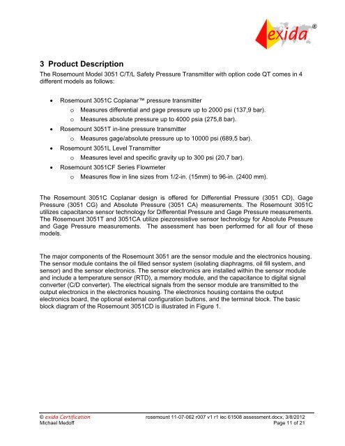
3 Product DescriptionThe <strong>Rosemount</strong> Model 3051 C/T/L <strong>Safety</strong> Pressure Transmitter with option code QT comes in 4different models as follows:<strong>Rosemount</strong> 3051C Coplanar pressure transmittero Measures differential and gage pressure up to 2000 psi (137,9 bar).o Measures absolute pressure up to 4000 psia (275,8 bar).<strong>Rosemount</strong> 3051T in-line pressure transmittero Measures gage/absolute pressure up to 10000 psi (689,5 bar).<strong>Rosemount</strong> 3051L Level Transmittero Measures level and specific gravity up to 300 psi (20,7 bar).<strong>Rosemount</strong> 3051CF Series Flowmetero Measures flow in line sizes from 1/2-in. (15mm) to 96-in. (2400 mm).The <strong>Rosemount</strong> 3051C Coplanar design is offered for Differential Pressure (3051 CD), GagePressure (3051 CG) and Absolute Pressure (3051 CA) measurements. The <strong>Rosemount</strong> 3051Cutilizes capacitance sensor technology for Differential Pressure and Gage Pressure measurements.The <strong>Rosemount</strong> 3051T and 3051CA utilize piezoresistive sensor technology for Absolute Pressureand Gage Pressure measurements. The assessment has been performed for all four of thesemodels.The major components of the <strong>Rosemount</strong> 3051 are the sensor module and the electronics housing.The sensor module contains the oil filled sensor system (isolating diaphragms, oil fill system, andsensor) and the sensor electronics. The sensor electronics are installed within the sensor moduleand include a temperature sensor (RTD), a memory module, and the capacitance to digital signalconverter (C/D converter). The electrical signals from the sensor module are transmitted to theoutput electronics in the electronics housing. The electronics housing contains the outputelectronics board, the optional external configuration buttons, and the terminal block. The basicblock diagram of the <strong>Rosemount</strong> 3051CD is illustrated in Figure 1.© exida Certification rosemount 11-07-062 r007 v1 r1 iec <strong>61508</strong> assessment.docx, 3/8/2012Michael Medoff Page 11 of 21