Glancing Angle X-ray Diffraction (GAXRD) Technique
Glancing Angle X-ray Diffraction (GAXRD) Technique
Glancing Angle X-ray Diffraction (GAXRD) Technique

You also want an ePaper? Increase the reach of your titles
YUMPU automatically turns print PDFs into web optimized ePapers that Google loves.
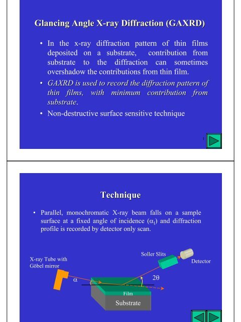
<strong>Glancing</strong> <strong>Angle</strong> X-<strong>ray</strong> X <strong>ray</strong> <strong>Diffraction</strong> (<strong>GAXRD</strong>)<br />
• In the x-<strong>ray</strong> diffraction pattern of thin films<br />
deposited on a substrate, contribution from<br />
substrate to the diffraction can sometimes<br />
overshadow the contributions from thin film.<br />
• <strong>GAXRD</strong> is used to record the diffraction pattern of<br />
thin films, with minimum contribution from<br />
substrate. substrate<br />
• Non-destructive surface sensitive technique<br />
<strong>Technique</strong><br />
• Parallel, monochromatic X-<strong>ray</strong> beam falls on a sample<br />
surface at a fixed angle of incidence (α I ) and diffraction<br />
profile is recorded by detector only scan.<br />
X-<strong>ray</strong> Tube with<br />
Göbel mirror<br />
α<br />
Film<br />
Substrate<br />
Soller Slits<br />
2θ<br />
1<br />
Detector<br />
2
Basics<br />
• When the angle of incidence (α I ) of X-<strong>ray</strong> beam<br />
decreases, so that the refractive index is less<br />
than unity, total external reflection of X-<strong>ray</strong>s<br />
occurs below the critical angle of incidence α C .<br />
The diffracted and scattered signals at the angle<br />
2θ arise mainly from the limited depth from the<br />
surface.<br />
ε<br />
ε’<br />
k<br />
E<br />
Scattering<br />
α<br />
z<br />
E”<br />
α<br />
α’<br />
E’<br />
k’<br />
k”<br />
x<br />
3<br />
4
Scattering<br />
Consider two homogenous slabs which have a<br />
plane interface at z=0. Let the medium above have<br />
the permittivity ε and below ε”. Suppose a plane,<br />
linearly polarized electromagnetic wave<br />
ur ur ur ur<br />
ikr ( . −ϖ<br />
t)<br />
E = Ee<br />
falls upon the interface from above<br />
r r<br />
k = wave vetor; r = position vector;<br />
ϖ = 2Πν<br />
ν = frequency of the radiation<br />
Scattering contd..<br />
There will be reflected wave<br />
ur ur<br />
ur ur<br />
( )<br />
".<br />
"<br />
above the interface and a refracted wave<br />
ik r t −ϖ<br />
E" = E e<br />
ur ur ur ur<br />
ik ( '. r−ϖt) E<br />
'= E 'e<br />
below the interface. α is the angle of incidence and α’ the<br />
angle of refraction<br />
Maxwell’s equations and the boundary conditions at z = 0<br />
determine the refracted and reflected waves in terms of<br />
parameters of the wave k and E.<br />
5<br />
6
Scattering contd..<br />
Collecting the relevant formulas for our purpose we get<br />
1 2<br />
ε '<br />
k'= ⎡ ⎤<br />
⎢⎣ε⎥⎦ k<br />
ε cosα = ε'cosα' Equation (1) is required by the Maxwell’s equations and (2) is<br />
Snell’s law (since the indices of refraction equal the square roots<br />
of the respective permittivity<br />
Amplitude of the refracted wave is linearly related to the amplitude<br />
of the incident , and is written as<br />
ur ur<br />
E ' =Φ.<br />
E<br />
where φ is a 2 nd rank tensor whose components can be expressed as<br />
Scattering contd..<br />
2 ( εε −ε<br />
1<br />
2 2 α )<br />
+ ( − )<br />
2 ' cos<br />
Φ = xx<br />
ε'sinα εε'ε cos α<br />
1<br />
2 2 2<br />
Eqs. (3) & (4), when expressed in more elementary terms<br />
for the separate cases of parallel and perpendicular<br />
polarization, are sometimes known as Fresnel’s equations<br />
(1)<br />
(2)<br />
(3)<br />
Φ yy =<br />
2 εsinα 1<br />
2 2<br />
εsinα + ( ε'−εcosα) 2εsinα Φ = zz<br />
1<br />
2 2 2<br />
ε'sinα + ( εε'−ε cos α)<br />
Φ =Φ =Φ =Φ =Φ =Φ = 0<br />
xy yx xz zx yz zy<br />
(4)<br />
7<br />
8
<strong>Glancing</strong> <strong>Angle</strong><br />
For high energy x-<strong>ray</strong>s, the refractive index of material is<br />
slightly less than unity, as a result of which material is for X<strong>ray</strong>s<br />
less refractive than it is for a vacuum. As the angle of<br />
incidence is reduced below a critical angle, X-<strong>ray</strong>s undergo<br />
total external reflection. Hence under these conditions, ε’< ε,<br />
and therefore α< α C , and is expressed as<br />
α = cos<br />
C<br />
1<br />
2<br />
−1 ⎡ε'⎤ ⎢⎣ε⎥⎦ Under these conditions, α’ becomes imaginary and the<br />
refracted wave propagates parallel to the interface while<br />
being exponentially damped below the interface.<br />
<strong>Glancing</strong> <strong>Angle</strong><br />
When α≤αC , the component of k’ become<br />
k'x= kcosα<br />
k ' = 0<br />
y<br />
1<br />
2<br />
⎡ 2 ε '⎤<br />
k' =−ik cos α z ⎢<br />
−<br />
⎣ ε ⎥⎦<br />
(6)<br />
Imaginary value of k z ’ provides damping, which is an<br />
essential feature of <strong>Glancing</strong> <strong>Angle</strong> geometry.<br />
(5)<br />
9<br />
10
Penetration Depth<br />
• Penetration depth defined as the length at which the field<br />
has fallen by a factor e-1 and can be expressed as<br />
1<br />
l ≡<br />
Im k 'z 1<br />
=<br />
1<br />
2 2<br />
k ( cos α −ε'/<br />
ε)<br />
λ<br />
≅<br />
2 2<br />
2Π<br />
α −α<br />
1<br />
2<br />
(7)<br />
( c )<br />
• However this term does not include absorption effects. On<br />
including absorption effect, equation (7) is modified as<br />
where<br />
{<br />
λ<br />
2 2 2 2 2 2<br />
l = ⎡ ( α − α ) + 4β + α −α<br />
⎤ 2<br />
C C<br />
4Π<br />
⎢⎣ ⎥⎦<br />
Penetration Depth<br />
µλ<br />
β =<br />
4Π<br />
}12 −<br />
(8)<br />
µ is the linear mass absorption coefficient<br />
λ is the the wavelength of the x-<strong>ray</strong>s<br />
• In the range of α=0 and when no absorption occurs equation<br />
(8) is expressed as<br />
λ<br />
l =<br />
4Πα C<br />
• For α> α C; the depth penetration depth is determined mainly<br />
by the photo absorption of the medium and is expressed as<br />
⎛sinα ⎞<br />
l ≅ ⎜<br />
µ<br />
⎟<br />
⎝ ⎠<br />
(9)<br />
11<br />
12
Penetration Depth Vs <strong>Angle</strong> of Incidence<br />
This figure shows penetration depth as a function of<br />
incident angle for Si 3 N 4 for CuK α (λ=0.154 nm) radiation<br />
Si 3 N 4<br />
α=0.5 o<br />
Penetration Depth Vs. Energy<br />
Penetration Depth (µm)<br />
Photon Energy (eV)<br />
• Spikes in the curve occur at energies corresponding to the<br />
characteristic absorption energies of the material.<br />
13<br />
14
Useful Applications<br />
• By reducing the angle of incidence, hence<br />
penetration of x-<strong>ray</strong>s in to the specimen, the<br />
contribution of substrate to the diffraction<br />
pattern can be minimized.<br />
• Alternatively, a specimen can be probed<br />
through its thickness by varying the angle of<br />
incidence.<br />
• (a) As deposited 20 nm Ir metal<br />
film deposited on Si wafer. XRD<br />
curve for αα=0.5 =0.5 o and 1.0 o shows<br />
the peaks for cubic iridium metal<br />
phase represented by (+)<br />
• (b) Ir film annealed at 873K for<br />
1hr. XRD curve for αα=0.5 =0.5o shows<br />
the presence of the dominating<br />
IrO 2 phase (*). As αα was<br />
increased to 1.0°, 1.0 the contribution<br />
from the underlying layer of Ir<br />
metal increased and the Ir peaks<br />
dominated the XRD curve. The<br />
results indicate the presence of an<br />
overlying oxidized layer of Ir<br />
metal<br />
<strong>GAXRD</strong>: Example<br />
15<br />
16
Experimental Issues<br />
• The diffraction peaks appear to shift to higher angles at<br />
small glancing angles.<br />
• For ααC, shift due to refraction caused by<br />
penetration of x-<strong>ray</strong> beam is approximately given as<br />
( ) ( ) 1<br />
θ α α α<br />
∆ 2 − −<br />
C<br />
2 2 2<br />
• In order to estimate crystallite size from FWHM, somewhat<br />
higher glancing angle than the α C for film should be used.<br />
17