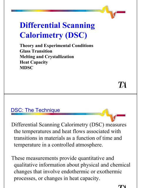
Differential Scanning Calorimetry (DSC)
Differential Scanning Calorimetry (DSC)
Differential Scanning Calorimetry (DSC)

Create successful ePaper yourself
Turn your PDF publications into a flip-book with our unique Google optimized e-Paper software.
<strong>Differential</strong> <strong>Scanning</strong><br />
<strong>Calorimetry</strong> (<strong>DSC</strong>)<br />
Theory and Experimental Conditions<br />
Glass Transition<br />
Melting and Crystallization<br />
Heat Capacity<br />
M<strong>DSC</strong><br />
<strong>DSC</strong>: The Technique<br />
<strong>Differential</strong> <strong>Scanning</strong> <strong>Calorimetry</strong> (<strong>DSC</strong>) measures<br />
the temperatures and heat flows associated with<br />
transitions in materials as a function of time and<br />
temperature in a controlled atmosphere.<br />
These measurements provide quantitative and<br />
qualitative information about physical and chemical<br />
changes that involve endothermic or exothermic<br />
processes, or changes in heat capacity.
TA Instruments <strong>DSC</strong>’s<br />
<strong>DSC</strong> 2010 <strong>DSC</strong> 2910 <strong>DSC</strong> 2920<br />
<strong>DSC</strong>: What <strong>DSC</strong> Can Tell You<br />
�Glass Transitions<br />
�Melting and Boiling Points<br />
�Crystallization time and temperature<br />
�Percent Crystallinity<br />
�Heats of Fusion and Reactions<br />
�Specific Heat<br />
�Oxidative/Thermal Stability<br />
�Rate and Degree of Cure<br />
�Reaction Kinetics<br />
�Purity
<strong>DSC</strong>: Definitions<br />
A calorimeter measures the heat into or out of a sample.<br />
A differential calorimeter measures the heat of a sample relative to<br />
a reference.<br />
A differential scanning calorimeter does all of the above and heats<br />
the sample with a linear temperature ramp.<br />
Endothermic heat flows into the sample.<br />
Exothermic heat flows out of the sample.<br />
<strong>DSC</strong>: Heat Flow/Specific Heat Capacity<br />
∆H = Cp ∆T<br />
or in differential form<br />
dH/dt = Cp dT/dt + thermal events<br />
where:<br />
Cp = specific heat (J/g°C)<br />
T = temperature (°C)<br />
H = heat (J)<br />
dH/dt = heat flow (J/min.)<br />
mW = mJ/sec<br />
dT/dt = heating rate (°C/min.)<br />
assuming work & mass loss are zero
<strong>DSC</strong>: Measurement of HF and T<br />
Sample Ref<br />
chromel alumel<br />
Ni-Cr Ni-Al<br />
<strong>DSC</strong>: Temperature Measurement<br />
Sample Ref<br />
Sample Temperature Ts<br />
constantan<br />
Cu-Ni<br />
Platinel Control<br />
Thermocouple<br />
Furnace<br />
Temperature<br />
Ag<br />
furnace
<strong>DSC</strong>: Heat Flow Measurement<br />
Alumel wire<br />
(sample temp)<br />
Sample Ref<br />
Potential Difference ∆U<br />
Temperature Difference ∆T<br />
Heat Flow dQ/dt<br />
Chromel<br />
wires (∆T)
<strong>DSC</strong>: Cell Schematic Diagram<br />
Chromel<br />
Disc<br />
Dynamic Sample Chamber<br />
Reference Pan<br />
Gas Purge Inlet<br />
Heating<br />
Block<br />
Alumel Wire<br />
Chromel Wire<br />
<strong>DSC</strong>: Cell Components<br />
Sample Pan<br />
Lid<br />
Chromel<br />
Disc<br />
Thermocouple<br />
Junction<br />
Thermoelectric Disc<br />
(Constantan)<br />
Silver Furnace: for good temperature<br />
uniformity<br />
Sample Purge: for excellent oxidative<br />
stability measurements<br />
Purge Preheated: for very low noise from<br />
turbulence<br />
Air Cool: for fast return to room<br />
temperature
<strong>DSC</strong>: Heat Flux Principle<br />
The differential temperature ( ∆ T)<br />
between the sample and<br />
reference is converted to differential heat flow in a way that<br />
is analogous to current flow in Ohms Law.<br />
I = E/R where: I = current<br />
E = voltage (potential)<br />
R = electrical resistance<br />
∆<br />
Heat Flow =<br />
T k 1 k 2 where:<br />
R<br />
∆T<br />
= temperature difference (potential)<br />
R = thermal resistance of constantan disk<br />
k 1 = factory-set calibration value<br />
k 2 = user-set calibration value<br />
<strong>DSC</strong>: How Heat Flux is Measured<br />
• Heat flow through the chromel wafer causes a<br />
temperature difference ∆T. The temperature<br />
difference is measured as the voltage difference ∆U<br />
between the sample and reference constantan/chromel<br />
junctions. The voltage is adjusted for thermocouple<br />
response S and is proportional to heat flow.<br />
∆T = ∆U / S ∆T in °C<br />
∆U in µV<br />
S in µV/°C
<strong>DSC</strong>: Related Instrumentation<br />
• Modulated <strong>DSC</strong> (M<strong>DSC</strong>) : sinusoidal oscillation superimposed<br />
on linear temperature ramp<br />
• <strong>Differential</strong> Thermal Analysis (DTA)<br />
• Pressure <strong>DSC</strong> (P<strong>DSC</strong>)<br />
• <strong>Differential</strong> Photocalorimetry (DPC)<br />
• Dual Sample <strong>DSC</strong><br />
• SDT 2960 Simultaneous <strong>DSC</strong>-TGA<br />
DTA<br />
<strong>Differential</strong> Thermal Analysis (DTA) : measures the temperatures and<br />
temperature differences (between sample and reference) associated with<br />
transitions in materials as a function of time and temperature in a<br />
controlled atmosphere
P<strong>DSC</strong><br />
Pressure <strong>DSC</strong> (P<strong>DSC</strong>) : capability<br />
of operating at elevated pressure or<br />
at a vacuum (TAI P<strong>DSC</strong>: 1 Pa - 7<br />
Mpa)<br />
DPC & Dual Sample <strong>DSC</strong><br />
•<strong>Differential</strong><br />
Photocalorimetry (DPC) :<br />
sample is exposed to<br />
UV/Vis radiation<br />
•Dual Sample <strong>DSC</strong>:<br />
Allows two samples to<br />
be ran simultaneously
SDT 2960<br />
•SDT 2960 Simultaneous <strong>DSC</strong>-TGA:<br />
measures heat flow and weight changes<br />
simultaneously<br />
<strong>DSC</strong>: Heat Flow Measurements<br />
Calorimeter Signals<br />
Time<br />
Temperature<br />
Heat Flow<br />
Signal Change Properties Measured<br />
Heat Flow, absolute Specific Heat<br />
Heat Flow, shift Glass Transition<br />
Exothermic Peak Crystallization or Cure<br />
Endothermic Peak Melting<br />
Isothermal Onset Oxidative Stability
<strong>DSC</strong>: Typical <strong>DSC</strong> Transitions<br />
Heat Flow -> exothermic<br />
Glass<br />
Transition<br />
Crystallization<br />
Melting<br />
Temperature<br />
<strong>DSC</strong>: Experimental Design<br />
�Available Method Segments<br />
�Method Design Rules<br />
�Typical Methods (Examples)<br />
Cross-Linking<br />
(Cure)<br />
Oxidation<br />
or<br />
Decomposition
<strong>DSC</strong>: Available Method Segments<br />
JUMP ABORT NEXT SEG*<br />
EQUILIBRATE SAMPLING INTERVAL<br />
INITIAL TEMPERATURE SELECT GAS<br />
RAMP EXTERNAL EVENT<br />
ISOTHERMAL DATA STORAGE<br />
ISO-TRACK AIR COOL*<br />
STEP LNCA CONTROL*<br />
INCREMENT MARK END OF CYCLE*<br />
REPEAT SEGMENT x FOR y TIMES MODULATE#<br />
REPEAT SEGMENT x TILL y °C<br />
* Available on <strong>DSC</strong> 29XX only<br />
# Available on M<strong>DSC</strong> 29XX only<br />
<strong>DSC</strong>: Method Design Rules<br />
�Start Temperature<br />
�Generally, the baseline should have three (3)<br />
minutes to completely stabilize prior to the<br />
transition of interest. Therefore, at 10°C/min.,<br />
start at least 30°C below the transition onset<br />
temperature<br />
�End Temperature<br />
�Allow a three (3) minute baseline after the<br />
transition of interest in order to correctly select<br />
integration or analysis limits
<strong>DSC</strong>: Heating/Cooling Method<br />
Heating Method<br />
(NOTE: No equilibrate segment necessary if<br />
starting at or near ambient temperature.)<br />
1) Ramp 10°C/min. to 300°C<br />
Cooling Method<br />
1) Equilibrate at 300°C<br />
2) Ramp 10°C/min. to 25°C<br />
<strong>DSC</strong>: Heat-Cool-Reheat Method<br />
Heat-Cool-Reheat Method<br />
1) LNCA control: High<br />
2) Ramp 10°C/min. to 300°C<br />
3) Mark cycle end 0<br />
4) Ramp 10°C/min. to 25°C<br />
5) Mark cycle end 0<br />
6) Ramp 10°C/min. to 300°C<br />
7) Mark cycle end 0<br />
The first segment in this method allows for rapid cooling
<strong>DSC</strong>: Oxidative Stability (OIT) Method<br />
OIT Method<br />
1) Equilibrate at 60°C<br />
2) Isothermal for 5.00 min.<br />
3) Ramp 20°C/min. to 200°C<br />
4) Isothermal for 5.00 min.<br />
5) Abort next seg. if W/g > 1.0<br />
6) Select gas: 2<br />
7) Iso-track for 200.00 min.<br />
<strong>DSC</strong>: Modulated <strong>DSC</strong> Method<br />
M<strong>DSC</strong> Method<br />
1) Data storage: off<br />
2) Equilibrate at -20°C<br />
3) Modulate ±1°C every 60 seconds<br />
4) Isothermal for 5.00 min.<br />
5) Data storage: on<br />
6) Ramp 3°C/min. to 300°C
<strong>DSC</strong>: Calibration & Sample Preparation<br />
�Instrument Calibration<br />
� <strong>Differential</strong> Heat Flow (Cell Constant)<br />
� Temperature<br />
� Baseline<br />
�Miscellaneous<br />
� Purge Gas<br />
� Cooling Accessories<br />
� Environment<br />
�Sample Preparation<br />
�Selecting Experimental Conditions<br />
�Routine Maintenance/Sample Press<br />
<strong>DSC</strong>: Heat Flow Calibration<br />
�<strong>Differential</strong> Heat Flow (ASTM E968)<br />
�Heat of fusion (melting) standards<br />
�Heat capacity (no transition)<br />
�Miscellaneous<br />
� Use specific purge gas at specified rate<br />
� Calibrate w/cooling accessory functioning if it will be<br />
used to run samples<br />
� Single point used for heat of fusion which is typically<br />
accurate to +/- 1-2% from -50°C to 350°C<br />
� Calibration should not change w/heating rate
Heat Flow (mW)<br />
<strong>DSC</strong>: Heat Flow Calibration<br />
�Prepare a 10 to 15 mg. sample of indium and premelt<br />
prior to first use<br />
�Use this sample a maximum of 10 times<br />
�Calibrate at least once a month<br />
�Typical values for cell constant: 1.0 to 1.2<br />
<strong>DSC</strong>: Calorimetric Calibration<br />
5<br />
0<br />
-5<br />
-10<br />
157.44°C<br />
Cell Const.: 1.0766<br />
Onset Slope: -20.82 mW/°C<br />
Sample: Indium, 5.95 mg.<br />
CALIBRATION MODE; 10°C/MIN<br />
CALIBRATION BASED ON 28.42J/g<br />
-15<br />
150 155 160 165 170
Heat Flow (W/g)<br />
<strong>DSC</strong>: Temperature Calibration<br />
�ASTM Method E967<br />
�Pure metals (indium, lead, etc.) typically used<br />
�Extrapolated onset is used as melting temperature<br />
�Sample is fully melted at the peak<br />
� Miscellaneous<br />
�With metal standards, calibration should change very<br />
� little with heating rate<br />
�With metal standards, it is not practical to calibrate for<br />
�changes in heating rate on polymer samples<br />
<strong>DSC</strong>: Temperature Calibration<br />
1<br />
0<br />
-1<br />
-2<br />
-3<br />
HEATING RATE<br />
Extrapolated Onset<br />
156.61°C<br />
28.36J/g<br />
-4<br />
157.09°C<br />
-5<br />
PEAK<br />
150 152 154 156 158 160 162 164<br />
50<br />
40<br />
30<br />
20<br />
10<br />
0<br />
Deriv. Temperature (°C/min)
<strong>DSC</strong>: Temperature Calibration<br />
�Calibrate at least once a month<br />
�Use at least two calibration points up to a maximum of<br />
five points<br />
�Use tin, lead, and zinc one time only<br />
<strong>DSC</strong>: Recommended Temperature &<br />
Enthalpy Standards<br />
Enthalpy<br />
(cell constant)<br />
Temperature<br />
�Benzoic acid (147.3 J/g) Tm = 123°C<br />
�Urea (241.8 J/g) Tm = 133°C<br />
�Indium (28.45 J/g) Tm = 156.6°C<br />
�Anthracene (161.9 J/g) Tm = 216°C<br />
�Cyclopentane* -150.77°C<br />
�Cyclopentane* -135.09°C<br />
�Cyclopentane* -93.43°C<br />
�Cyclohexane# -83°C<br />
�Water# 0°C<br />
�Gallium# 29.76°C<br />
�Phenyl Ether# 30°C<br />
�p-Nitrotoluene� 51.45°C<br />
�Naphthalene� 80.25°C<br />
�Indium# 156.60°C<br />
�Tin# 231.95°C<br />
* GEFTA recommended<br />
Thermochim. Acta, 219 (1993) 333.<br />
# ITS 90 Fixed Point<br />
� Zone refined organic compound<br />
(sublimes)
<strong>DSC</strong>: Traceable Calibration Materials<br />
�NIST <strong>DSC</strong> calibration materials:<br />
�SRM 2232 Indium Tm = 156.5985°C<br />
� SRM 2220 Tin Tm = 231.95°C<br />
� SRM 2222 Biphenyl Tm = 69.41°C<br />
� SRM 2225 Mercury Tm = -38.70°C<br />
� SRM 2221b Zinc Tm = In Preparation<br />
�NIST: Gaithersburg, MD 20899-0001<br />
� Phone: 301-975-6776<br />
� Fax: 301-948-3730<br />
� Email: SRMINFO@nist.gov<br />
� www: HTTP://ts.nist.gov/srm<br />
<strong>DSC</strong>: Traceable Calibration Materials<br />
�LGC <strong>DSC</strong> Calibration Materials:<br />
�LGC2601: Indium (TA p/n: 915060-901)<br />
� LGC2608: Lead<br />
� LGC2609: Tin<br />
� LGC2611: Zinc<br />
�Laboratory of the Government Chemist, UK<br />
� Phone: 44 (0) 181 943 7565<br />
� Fax: 44 (0) 181 943 7554<br />
� Email: orm@lgc.co.uk
<strong>DSC</strong>: Traceable Calibration Materials<br />
�Certified materials used to establish traceability of<br />
instrument calibration<br />
�ISO/GLP certification often requires third party<br />
calibration of instruments:<br />
� Service provided by TA Instruments service<br />
representative using certified materials<br />
� Certificate of Calibration issued showing traceability<br />
of calibration to a national laboratory<br />
<strong>DSC</strong>: Effect of Heating Rate<br />
on Indium Melting Temperature<br />
Heat Flow (W/g)<br />
1<br />
0<br />
-1<br />
-2<br />
-3<br />
-4<br />
Heating Rates = 2, 5, 10, & 20°C/min<br />
-5<br />
154 156 158 160 162 164 166 168 170<br />
Temperature (°C)
<strong>DSC</strong>: Effect of Heating Rate<br />
on Indium Melting Temperature<br />
Heat Rate Onset Peak ∆H<br />
Onset<br />
Variation<br />
to 10°C/min<br />
2°C/min 156.49°C 156.61°C 28.46 J/g -0.12°C<br />
5 156.54 156.75 28.45 -0.07<br />
10 156.61 156.87 28.46 0<br />
20 156.76 157.08 28.44 +0.15<br />
<strong>DSC</strong>: Polymer Sample w/Internal<br />
Temperature Calibration Material<br />
2 Layers<br />
of Polymer<br />
Film<br />
Melting Point<br />
Standard, e.g.<br />
Indium<br />
Typical weight of polymer sample is 10mg<br />
(2 films at 5mg each) with 1-3mg of Indium
<strong>DSC</strong>: Indium Sample Placed Between<br />
Two HDPE Film Samples<br />
Sample: Linear Polyethylene-Indium<br />
Size: 10.0000 mg<br />
Method: VarHeat <strong>DSC</strong><br />
Operator: Lab<br />
Run Date: 11-Jun-97 12:43<br />
Comment: <strong>DSC</strong> @ 2,5,10%20°C/min; crimped pans, HS Cmpd<br />
Heat Flow (W/g)<br />
0<br />
-2<br />
-4<br />
Polyethylene<br />
Melt<br />
Indium<br />
Melt<br />
-6<br />
20 40 60 80 100 120 140 160 180<br />
Temperature (°C)<br />
<strong>DSC</strong>: Effect of Heating Rate on HDPE<br />
and Indium Melting<br />
Heat Flow (W/g)<br />
0<br />
-2<br />
-4<br />
-6<br />
Polyethylene<br />
Melt<br />
Indium<br />
Melt<br />
-8<br />
20 40 60 80 100 120 140 160 180<br />
Temperature (°C)
Heat Flow (W/g)<br />
0.5<br />
0.0<br />
-0.5<br />
-1.0<br />
-1.5<br />
When Placed Between Polymer Films<br />
Heating Rates = 2, 5, 10 & 20°C/min<br />
-2.0<br />
154 156 158 160 162 164 166 168 170<br />
Temperature (°C)<br />
<strong>DSC</strong>: Effect of Heating Rate on Indium Melting<br />
When Placed Between Polymer Film<br />
Onset Variation When Calibrated at 10°C/min.<br />
Heating Rate<br />
Standard<br />
Sample<br />
Polymer Sandwich<br />
Sample<br />
2°C/min -0.12°C +.03°C<br />
5 -0.07 +.16<br />
10 0 +0.44<br />
20 +0.15 +0.82
<strong>DSC</strong>: Baseline Calibration<br />
�Slope<br />
�Calibration should provide flat baseline with<br />
empty pans<br />
�Polymers should always have an endothermic<br />
slope due to increasing heat capacity with<br />
increasing temperature<br />
�Curvature<br />
�Not normally part of calibration procedure<br />
�Can be eliminated if necessary with baseline<br />
subtraction<br />
�Curvature can cause errors in analyses<br />
<strong>DSC</strong>: Baseline Slope<br />
Heat Flow (W/g)<br />
0.5<br />
0.0<br />
-0.5<br />
-1.0<br />
-1.5<br />
Empty Pans<br />
10 mg Polystyrene<br />
-2.0<br />
20 40 60 80 100 120 140 160 180 200
<strong>DSC</strong>: Baseline Curvature<br />
Heat Flow (W/g)<br />
0.1<br />
0.0<br />
-0.1<br />
-0.2<br />
100 150 200 250 300 350<br />
Temperature (°C)<br />
SDT 2960 Calibration<br />
Heating @ 1°C/min<br />
Heating @ 3.5°C/min<br />
•DTA Baseline and empty beams<br />
0.4<br />
0.2<br />
0.0<br />
-0.2<br />
TGA Weight Calibration calibration weights<br />
•Temperature Calibration up to 5 temperature<br />
standards<br />
•<strong>DSC</strong> Heat Flow Calibration sapphire<br />
Heat Flow (W/g)
SDT 2960 <strong>DSC</strong> Heat Flow Calibration<br />
•Two scans from ambient to 1500°C at 20 °C/min<br />
•empty alumina pans<br />
•sapphire in alumina sample pan<br />
•Use Thermal Solutions/Thermal Advantage NT<br />
Software to analyze<br />
•E-curve will be calculated and transferred to the<br />
module when the user accepts the results<br />
<strong>DSC</strong>: Instrument Preparation<br />
�Purge Gas<br />
�Type of purge gas and flow rate affect calibration and therefore<br />
should be controlled<br />
�Nitrogen is preferred because it is inert and calibration is least<br />
affected by changes in flow rate<br />
�Cooling Accessories<br />
�If used, they should be operating and equilibriated prior to<br />
calibration or sample runs<br />
�Warm-up Time/Environment<br />
�Electronics should be given at least one hour to stabilize for<br />
important samples if the instrument has been turned OFF<br />
�Electronics are effected by ambient temperature. Avoid areas such<br />
as hoods or near an air conditioner
Cell Constant<br />
<strong>DSC</strong>: Recommended Purge Gas Flow<br />
Rates & Effect of Flow Rate<br />
Purge Port (mL/min.)<br />
Module Purge Cool Vacuum<br />
<strong>DSC</strong> 2920/2910/2010 50 (N ) 50*<br />
2<br />
25 (He) 50<br />
* Only needed for subambient or M<strong>DSC</strong> use. Use dry nitrogen or He gas<br />
Purge Gas Flow Rate Too Slow: Moisture Accumulation and Early<br />
Aging of the Cell<br />
�Purge Gas Flow Rate Too Fast: Excessive Noise<br />
<strong>DSC</strong>: Effect of Flow Rate on Cell Constant<br />
1.80<br />
1.70<br />
1.60<br />
1.50<br />
1.40<br />
1.30<br />
1.20<br />
1.10<br />
1.00<br />
Helium Cell Constant<br />
Nitrogen Cell Constant<br />
0 10 20 30 40 50 60 70 80 90 100 110
<strong>DSC</strong>: Sample Preparation<br />
�Sample Weight<br />
� Selection of the optimum weight is dependent on a number of factors.<br />
The sample to be analyzed must be representative of the total sample<br />
�The change in heat flow due to the transition of interest should be<br />
in the range of 0.1 - 10mW<br />
- metal or chemical melting: 10mg<br />
�The accuracy of the analytical balance<br />
- sample weight should be accurate to +1%<br />
<strong>DSC</strong>: Heat Flow Change During a<br />
Transition<br />
Heat Flow (mW)<br />
1.0<br />
0.5<br />
0.0<br />
-0.5<br />
-1.0<br />
-1.5<br />
69.41°C<br />
73.37°C(H)<br />
+ 0.4881mW<br />
143.70°C<br />
34.95J/g<br />
161.17°C<br />
1.593mW<br />
-2.0<br />
40 60 80 100 120 140 160 180 200 220<br />
Temperature (°C)
<strong>DSC</strong>: Sample Preparation (cont.)<br />
�Sample Shape<br />
� Keep sample as thin as possible and cover as much of the pan bottom<br />
as possible<br />
� Samples should be cut rather than crushed to obtain a thin sample<br />
� Lids should be used with sample pans in order to keep the sample in<br />
contact with the bottom of the pan<br />
�Sample Pans<br />
� Use lightest, flattest pan possible<br />
� Use hermetic pans to prevent evaporation if it occurs in the same<br />
temperature range as the transition of interest<br />
<strong>DSC</strong>: Experimental Conditions<br />
�Reference Pan<br />
�Always use a reference pan of the same type used to prepare the<br />
sample<br />
�Never use a material in the reference pan that has a transition in<br />
the temperature range of interest<br />
�Because <strong>DSC</strong> measures the difference in heat flow between a<br />
sample and reference, the baseline stabilizes faster if the difference<br />
in heat capacity between the sample and reference is kept small by<br />
adding weight (same material as pan) to the reference pan so that it<br />
is similar in total weight to the sample pan.
<strong>DSC</strong>: Effect of Reference Pan Weight<br />
on <strong>DSC</strong> Baseline<br />
Heat Flow (mW)<br />
4<br />
2<br />
0<br />
-2<br />
-4<br />
-6<br />
-8<br />
-10<br />
Sample: Epoxy<br />
Weight: Approx. 10mg<br />
Heat Rate: 20°C<br />
REFERENCE PAN WITH 2 LIDS<br />
1.688mW<br />
REFERENCE PAN WITH 1.5 LIDS<br />
-0.6018mW<br />
-1.953mW<br />
REFERENCE PAN WITH LID<br />
-10.04mW<br />
NO REFERENCE PAN<br />
-12<br />
90 110 130<br />
Temperature °C<br />
150 170<br />
<strong>DSC</strong>: Comparison of <strong>DSC</strong> Tg Using No Reference<br />
Pan and One of Equal Cp to Sample<br />
Heat Flow (mW)<br />
0.2<br />
0<br />
-0.2<br />
-0.4<br />
-0.6<br />
Cp REF = Cp SAMPLE<br />
NO REFERENCE<br />
-0.8<br />
90 110 130 150 170
<strong>DSC</strong>: Experimental Conditions<br />
�Heating/Cooling Rates<br />
�High rates increase sensitivity<br />
dQ<br />
dt<br />
heat flow<br />
measured<br />
by <strong>DSC</strong><br />
dT<br />
= Cp x<br />
dt<br />
= heat capacity<br />
or weight<br />
of sample<br />
x heating<br />
rate<br />
+ (T, t) f<br />
+ time dependent<br />
or kinetic<br />
component<br />
�Low rates increase resolution by providing more time at any<br />
temperature<br />
�Purge Gas<br />
�nitrogen increases sensitivity because it is a relatively poor thermal<br />
conductor<br />
�helium increases resolution because it is a good conductor<br />
of heat to or from the sample<br />
<strong>DSC</strong>: Experimental Conditions<br />
General Summary<br />
Condition<br />
To Increase<br />
Sensitivity<br />
To Increase<br />
Resolution<br />
Sample Size Increase Decrease<br />
Heat Rate Increase Decrease<br />
Ref Pan Weight Increase No Effect<br />
Purge Gas Nitrogen* Helium*<br />
*instrument should be calibrated with the same<br />
purge gas as used to run a sample
<strong>DSC</strong>: Sample Pan Types<br />
�Pan Type<br />
�Aluminum<br />
�Copper<br />
�Gold<br />
�Graphite<br />
�Al Hermetic<br />
�Al Alodined Hermetic<br />
�Gold Hermetic<br />
�High Volume (100µL)<br />
�Al Solid Fat Index (SFI)<br />
�Platinum<br />
<strong>DSC</strong>: Sample Pan Selection<br />
Standard Aluminum Pans<br />
�Upper Temp Limit<br />
�600°C<br />
�725°C (in N2)<br />
�725°C<br />
�725°C (in N2)<br />
�600°C (3 atm.)<br />
�600°C (3 atm.)<br />
�725°C (6 atm.)<br />
�250°C (safety lid)<br />
�600°C (no cover)<br />
�725°C (no cover)<br />
Use a thin layer<br />
Distribute material<br />
evenly
<strong>DSC</strong>: Sample Preparation – Hermetic Pans<br />
<strong>DSC</strong>: Sample Pan Selection<br />
Spread Material Evenly<br />
Do not overfill!!<br />
�Sample Type Measurement Pan Type<br />
solid Tg,Tm std., hermetic, open<br />
(nonvolatile) OIT SFI, open<br />
Cp std.<br />
solid (volatile) Cp hermetic<br />
liquid Tn,Tc,Tg,Tm hermetic, SFI, open<br />
Cp hermetic<br />
OIT SFI, open<br />
aqueous solution Cp,Tm,Tg alodined or gold<br />
hermetic<br />
foods/biologicals denaturation high volume
<strong>DSC</strong>: Recommended Cell Maintenance<br />
�Cleaning the <strong>DSC</strong> cell (bakeout)<br />
(use this procedure for cleaning a contaminated cell)<br />
�Air purge = 50mL/min.<br />
�Ramp 20°C/min. to 600°C<br />
�Isothermal for 10 min.<br />
�Cool cell to room temperature<br />
�Brush out cell with fiberglass brush<br />
�Check for improved baseline performance<br />
�NEVER use solvents to clean <strong>DSC</strong> cell<br />
Thermoplastic Polymers<br />
Semi-Crystalline (or Amorphous)<br />
Crystalline Phase<br />
melting temperature Tm<br />
(endothermic peak)<br />
Amorphous Phase<br />
glass transition<br />
temperature (Tg)<br />
(causing ∆Cp)<br />
Tg < Tm<br />
Crystallizable polymer can crystallize<br />
on cooling from the melt at Tc
<strong>DSC</strong>: Selecting Experimental Conditions<br />
�Thermoplastic Polymers<br />
� Perform a Heat-Cool-Heat Experiment at 10°C/min.<br />
� First heat data is a function of the material and an unknown thermal<br />
history<br />
� Cooling segment data provides information on the crystallization<br />
properties of the polymer and gives the sample a known thermal<br />
history<br />
� Second heat data is a function of the material with a known thermal<br />
history<br />
<strong>DSC</strong>: Thermoplastic: Heat/Cool/Heat<br />
Heat Flow (W/g)<br />
0.4<br />
0.2<br />
0.0<br />
-0.2<br />
-0.4<br />
-0.6<br />
-0.8<br />
First Heat<br />
Cooling<br />
Second<br />
Heat<br />
0 20 40 60 80<br />
300<br />
250<br />
200<br />
150<br />
100<br />
50<br />
0<br />
[ ] Temperature (°C)
<strong>DSC</strong>: Thermoplastic: Heat Flow vs.<br />
Temperature for Heat/Cool/Heat<br />
Heat Flow (W/g)<br />
0.4<br />
0.2<br />
0.0<br />
-0.2<br />
-0.4<br />
-0.6<br />
Second Heat<br />
191.41°C<br />
First Heat<br />
Cool<br />
223.01°C<br />
48.03J/g<br />
-0.8<br />
20 40 60 80 100 120 140 160 180 200 220 240 260 280<br />
Temperature (°C)<br />
<strong>DSC</strong>: Selecting Experimental Conditions<br />
�Thermoplastic Polymers (con't)<br />
Interpreting Heat-Cool-Heat Results:<br />
One of the primary benefits of doing Heat-Cool-Heat is for the<br />
comparison of two or more samples which can differ in<br />
material, thermal history or both<br />
�If the materials are different then there will be differences in the Cool and<br />
Second Heat results<br />
�If the materials are the same and they have had the same thermal history<br />
then all three (H-C-H) segments will be similar<br />
�If the materials are the same but they have had different thermal histories<br />
then the Cool and Second Heat segments are similar but the First Heats<br />
are different
Selecting Experimental Conditions<br />
• During first heat the maximum temperature must be<br />
higher than the melting peak end; eventually an<br />
isothermal period must be introduced<br />
– too high temperature/time: decomposition could<br />
occur<br />
– too low temperature/time: possibly subsequent<br />
memory effect because of the fact that crystalline<br />
order is not completely destroyed<br />
• For non-crystallizable (amorphous) thermoplastics the<br />
maximum temperature should be slightly above Tg<br />
(removal of relaxation effects, avoid decomposition)<br />
Thermosetting Polymers<br />
A + B C<br />
Thermosetting polymers react (cross-link) irreversibly.<br />
A+B will give out heat (exothermic) when they crosslink<br />
(cure). After cooling and reheating C will have only<br />
a glass transition Tg.<br />
GLUE
<strong>DSC</strong>: Selecting Experimental Conditions<br />
Heat Flow (W/g)<br />
�Thermosetting Polymers<br />
Anneal the sample, then Heat-Cool-Heat at 10°C/min.<br />
�Anneal approximately 25°C above Tg onset for 1 minute to<br />
eliminate enthalpic relaxation from Tg<br />
�First Heat is used to measure Tg and residual cure (unreacted<br />
resin). Stop at a temperature below the onset of decomposition<br />
�Cooling segment gives the sample a known thermal history<br />
�Second Heat is used to measure the Tg of the fully cured sample.<br />
The greater the temperature difference between the Tg of the First<br />
and Second Heats the lower the degree of cure of the sample as<br />
received<br />
<strong>DSC</strong>: Effect of Annealing on the Shape<br />
of the Glass Transition<br />
0.0<br />
-0.1<br />
-0.2<br />
-0.3<br />
-0.4<br />
annealed<br />
aged<br />
0 10 20 30 40 50 60 70 80 90 100<br />
0.4<br />
0.2<br />
0.0<br />
-0.2<br />
Heat Flow (W/g)
Heat Flow (W/g)<br />
Heat Flow (W/g)<br />
<strong>DSC</strong>: Thermoset: Comparison of First<br />
and Second Heating Runs<br />
-0.04<br />
-0.08<br />
-0.12<br />
-0.16<br />
-0.20<br />
-0.24<br />
First<br />
Second<br />
Tg<br />
Tg<br />
155.93°C<br />
102.64°C<br />
20.38J/g<br />
Residual Cure<br />
0 50 100 150 200 250 300<br />
Temperature (°C)<br />
<strong>DSC</strong>: Determination of % Cure<br />
2.0<br />
1.5<br />
1.0<br />
0.5<br />
0.0<br />
<strong>DSC</strong> Conditions:<br />
Heating Rate = 10°C/min.<br />
Temperature Range = -50°C to 250°C<br />
N2 Purge = 50mL/min.<br />
-5.27°C(H)<br />
-12.61°C(H)<br />
NOTE: Curves rescaled and shifted for readability<br />
145.4J/g<br />
54.55 % cured<br />
79.33J/g<br />
75.21 % cured<br />
Under-cured Sample<br />
Optimally-cured Sample
<strong>DSC</strong>: Characterization of Epoxy Prepreg<br />
<strong>DSC</strong>: The Glass Transition (Tg)<br />
�What is it?<br />
�How is it observed and measured?<br />
�What affects the Glass Transition?
<strong>DSC</strong>: What is the Glass Transition?<br />
The Glass Transition is the reversible change of the<br />
amorphous region of a polymer from, or to, a viscous or<br />
rubbery condition to, or from, a hard and relatively brittle<br />
one.<br />
The Glass Transition Temperature is a temperature taken to<br />
represent the temperature range over which the glass<br />
transition takes place.<br />
<strong>DSC</strong>: Some Properties Affected at Tg<br />
Physical property Response on heating<br />
through Tg<br />
Specific Volume Increases<br />
Modulus Decreases<br />
Coefficient of<br />
thermal expansion<br />
Increases<br />
Specific Heat Increases<br />
Enthalpy Increases<br />
Entropy Increases<br />
V,<br />
1/E,<br />
CTE<br />
Cp<br />
H &<br />
S<br />
Tg<br />
Temperature
<strong>DSC</strong>: Measurements of the Tg<br />
endo HEAT FLOW exo<br />
Heat Flow (mW)<br />
T o<br />
1/2h<br />
1/2h<br />
T f<br />
T m<br />
T o =Temperature of First Deviation ( C)<br />
o<br />
T f = Extrapolated Onset Temperature ( C)<br />
o<br />
T m = Midpoint Temperature ( C)<br />
o<br />
T i = Inflection Temperature ( C)<br />
o<br />
T e = Extrapolated Endset Temperature ( C)<br />
o<br />
T = Temperature of Return-to-Baseline ( C)<br />
T i Te T r<br />
TEMPERATURE (°C)<br />
<strong>DSC</strong>: Polyethylene Terephthalate<br />
Glass Transition<br />
-0.6<br />
-0.7<br />
-0.8<br />
-0.9<br />
-1.0<br />
40 60 80 100 120<br />
r<br />
71. 54° C<br />
79. 88° C<br />
0. 3005mW<br />
o
<strong>DSC</strong>: What Affects the Glass Transition?<br />
Heating Rate Crystalline Content<br />
Heating & Cooling Copolymers<br />
Aging Side Chains<br />
Molecular Weight Polymer Backbone<br />
Plasticizer Hydrogen Bonding<br />
Filler<br />
<strong>DSC</strong>: Heating Rate<br />
Heating Rate Sensitivity Reproducibility<br />
(°C/min)<br />
5 poor very good<br />
20* good good<br />
40 very good poor<br />
* Recommended heating rate for measuring Tg.
Heat Capacity (J/g/°C)<br />
<strong>DSC</strong>: Heating/Cooling of Polystyrene<br />
<strong>DSC</strong> Heat Flow (W/g)<br />
0.15<br />
0.10<br />
0.05<br />
0.00<br />
-0.05<br />
-0.10<br />
10 °C/min COOLING<br />
10 °C/min HEATING<br />
75 80 85 90 95 100 105 110 115<br />
Temperature (°C)<br />
M<strong>DSC</strong>: Heating/Cooling of Polystyrene<br />
1.00<br />
0.90<br />
0.80<br />
0.70<br />
0.60<br />
5 °C/min HEATING<br />
5 °C/min COOLING<br />
0.50<br />
75 80 85 90 95 100 105 110 115
Effect of Cooling Rate on Tg<br />
Heat Capacity (J/g°C)<br />
2.0<br />
1.8<br />
1.6<br />
1.4<br />
1.2<br />
1.0<br />
Heat Capacity Measured<br />
After Cooling at Quench,<br />
20, 10, 5, 2, 1 and 0.2°C/min<br />
increased amorphous<br />
fraction<br />
Quench<br />
20<br />
10<br />
20 40 60 80 100 120 140 160<br />
Temperature (°C)<br />
<strong>DSC</strong>: Effect of Aging on the Glass<br />
Transition [M. Todoki, Polymer Data Handbook]<br />
As-Spun<br />
2 days<br />
28 days<br />
196 days<br />
3 years and<br />
2 months<br />
4 years and<br />
11 months<br />
Glass Transition<br />
0 50 100 150<br />
0.2<br />
Cold Crystallization
<strong>DSC</strong>: Effect of Annealing on Polystyrene<br />
Sample:<br />
Size:<br />
Method:<br />
Polystyrene; effect anneal @ 95°<br />
11.6600 mg<br />
Anneal Times <strong>DSC</strong><br />
Operator: Lab<br />
Run Date: 3-Jun-97 16:41<br />
Comment: <strong>DSC</strong> @ 10°C/min; N2 @ 50cc/min; 12.8mg A1 in ref.; crimped pans<br />
Heat Flow (W/g)<br />
0.2<br />
0.1<br />
0.0<br />
-0.1<br />
-0.2<br />
Anneal Times = 0, 10, 100 & 1000 minutes<br />
-0.3<br />
40 60 80 100 120 140 160<br />
Temperature (°C)<br />
<strong>DSC</strong>: Effect of Annealing Time at 95°C<br />
on Shape of Polystyrene Tg<br />
Heat Fl ow ( W/ g)<br />
0. 00<br />
-0.05<br />
-0.10<br />
-0.15<br />
-0.20<br />
Anneal Times = 0, 10, 100 & 1000 minutes<br />
-0.25<br />
80 90 100 110 120 130
<strong>DSC</strong>: Effect of Molecular Weight<br />
on the Tg (for Styrene Oligomers/Polymers)<br />
Molecular Weight Tg<br />
104 -138°C<br />
524 - 40°C<br />
2,210 40°C<br />
3,100 62°C<br />
15,100 86°C<br />
36,000 94°C<br />
170,000 100°C<br />
Turi, pg 249 Kumler, 1977<br />
<strong>DSC</strong>: Effect of Plasticizer on the Tg<br />
for Polyamides<br />
Water Content (%) Tg (°C)<br />
0.35 94<br />
0.70 84<br />
1.17 71<br />
1.99 56<br />
2.70 45<br />
4.48 40<br />
6.61 23<br />
10.33 6
<strong>DSC</strong>: Effect of Filler and Crystalline<br />
Content on the Tg<br />
�Decreases magnitude of Cp shift<br />
�Broadens temperature range of Glass Transition<br />
�Increases the Tg<br />
<strong>DSC</strong>: Copolymers<br />
Tg (K)<br />
490<br />
450<br />
410<br />
370<br />
0 20 40 60 80 100<br />
PPO (wt. %)
<strong>DSC</strong>: Effect of Side Chains on the Tg<br />
for - CH 2 - CH(R)-<br />
Side Chain Tg (°C)<br />
-H<br />
-36<br />
-CH<br />
3<br />
-12<br />
-CH<br />
2<br />
(CH<br />
3<br />
)<br />
64<br />
−C<br />
6<br />
H<br />
5<br />
100<br />
cyclohexyl<br />
120<br />
-C<br />
6<br />
H<br />
4<br />
-(4-C<br />
6<br />
H<br />
5<br />
)<br />
161<br />
<strong>DSC</strong>: Effect of Polymer Backbone<br />
on the Tg<br />
for -O-(CH 2 ) n -<br />
N Tg (°C)<br />
2 -41<br />
3 -78<br />
4 -84
<strong>DSC</strong>: Effect of Hydrogen Bonding<br />
on the Tg<br />
Polyamide Tg (°C) HBonding<br />
Nylon 12,2 59 Least<br />
Nylon 10,2 56<br />
Nylon 8,2 93<br />
Nylon 6,2 159 Most<br />
<strong>DSC</strong>: Melting and Crystallization<br />
�Terminology<br />
�Observations of Melting and Crystallization<br />
�Crystallinity Calculations<br />
�Applications
<strong>DSC</strong>: Terminology<br />
�Amorphous Phase - The portion of material whose molecules are randomly oriented in space. Liquids<br />
and glassy or rubbery solids. Thermosets and some thermoplastics.<br />
�Crystalline Phase - The portion of material whose molecules are regularly arranged into well defined<br />
structures consisting of repeat units. Very few polymers are 100% crystalline.<br />
�Semi-crystalline Polymers - Polymers whose solid phases are partially amorphous and partially<br />
crystalline. Most common thermoplastics are semi-crystalline.<br />
�Endothermic - A transition which absorbs energy.<br />
�Exothermic - A transition which releases energy.<br />
�Melting - The endothermic transition upon heating from a crystalline solid to the liquid state. This process<br />
is also called fusion. The melt is another term for the polymer liquid phase.<br />
�Crystallization - The exothermic transition upon cooling from liquid to crystalline solid. Crystallization<br />
is a function of time and temperature.<br />
�Cold Crystallization - The exothermic transition upon heating from the amorphous rubbery state to the<br />
crystalline state. This only occurs in semi-crystalline polymers that have been quenched (very rapidly<br />
cooled from the melt) into a highly amorphous state.<br />
�Enthalpy of Melting/Crystallization - The heat energy required for melting or released upon<br />
crystallization. This is calculated by integrating the area of the <strong>DSC</strong> peak on a time basis.<br />
Heat Flow (W/g)<br />
Observation of Melting<br />
0.0<br />
-0.2<br />
-0.4<br />
-0.6<br />
-0.8<br />
-1.0<br />
236.94°C<br />
45.30J/g<br />
12.73°C<br />
250.61°C<br />
Peak Temperature<br />
Extrapolated Onset Temperature<br />
Area under the curve (Heat of Fusion)<br />
Width @ half height
<strong>DSC</strong>: Melting Points and Ranges<br />
• To is the onset to melting<br />
• Tp is the melting peak temperature<br />
• Te is the end of melting<br />
Pure, low molecular weight materials (mw
Baseline Types: Linear<br />
Heat Flow (W/g)<br />
0.3<br />
0.2<br />
0.1<br />
12.20°C<br />
16.10°C<br />
22.27(24.02)J/g<br />
1.754J/g<br />
0.0<br />
-20 -10 0 10 20 30 40<br />
Exo Up Temperature (°C)<br />
Universal V2.5D TA Instruments<br />
Baseline Types: Sigmoidal<br />
Heat Flow (W/g)<br />
0.3<br />
0.2<br />
0.1<br />
12.20°C<br />
23.04J/g
<strong>DSC</strong>: Observation of Crystallization<br />
Heat Flow (mW)<br />
1.0<br />
0.5<br />
0.0<br />
-0.5<br />
-1.0<br />
139.47°C<br />
36.60J/g<br />
-1.5<br />
100 120 140 160 180 200<br />
<strong>DSC</strong>: Crystallization Point<br />
152.62°C<br />
Te<br />
Tc<br />
Temperature (°C)<br />
�Crystallization is a two step process:<br />
�Nucleation<br />
�Growth<br />
163.24°C<br />
�The onset temperature is the nucleation (T )<br />
�The peak maximum is the crystallization<br />
temperature (T )<br />
C<br />
Tn<br />
N
<strong>DSC</strong>: PET/ABS Blend "As Received"<br />
Heat Flow (W/g)<br />
-0.2<br />
-0.4<br />
-0.6<br />
-0.8<br />
67. 38° C<br />
+<br />
70. 26° C( H)<br />
120. 92° C<br />
111. 82° C<br />
9. 016J/ g<br />
STANDARD <strong>DSC</strong><br />
FIRST HEAT ON MOLDED PART<br />
235. 36° C<br />
22. 63J/ g<br />
249. 75° C<br />
50 100 150<br />
Temperature (°C)<br />
200 250<br />
<strong>DSC</strong>: Calculation of % Crystallinity<br />
�Sample must be pure material, not copolymer or filled<br />
�Must know enthalpy of melting for 100% crystalline<br />
material (∆H lit )<br />
�You can use a standard ∆H for relative crystallinity<br />
For standard samples:<br />
% crystallinity = 100* ∆H m / ∆H lit<br />
For samples with cold crystallization:<br />
% crystallinity = 100* (∆H m - ∆H c)/ ∆H lit<br />
lit
<strong>DSC</strong>: Polymer Crystallinity - Polyolefin<br />
ENDO HEAT FLOW EXO<br />
0<br />
∆H<br />
= 141 J/g<br />
141<br />
% Crystallinity = X 100%<br />
290<br />
= 49%<br />
Size: 10.5mg<br />
Prog: 5° C/min<br />
<strong>DSC</strong>: Applications<br />
2 4 6 8 10 12 14<br />
TIME (min)<br />
�Effect of heating/cooling rate<br />
�Crystallization kinetics<br />
�Effects of polymer structure/composition<br />
�Effects of thermal/mechanical processing<br />
190<br />
170<br />
150<br />
130<br />
110<br />
90<br />
TEMPERATURE (°C)
<strong>DSC</strong>: Effect of Heating Rate on<br />
Nylon 66 Melting Behavior<br />
endo HEAT FLOW exo<br />
0.2 mW<br />
1 mW<br />
5 mW<br />
5 mW<br />
10 mW<br />
0.5°C/min<br />
2°C/min<br />
10°C/min<br />
20°C/min<br />
50°C/min<br />
1 240 2 260 280 300 3 4<br />
Temperature (°C)<br />
<strong>DSC</strong>: Effect of Cooling Rate on<br />
Crystallization of HDPE<br />
Heat Flow (mW)<br />
70<br />
50<br />
30<br />
10<br />
32°C/min<br />
16<br />
-10<br />
100 110 120 130<br />
Temperature (°C)<br />
8<br />
4<br />
2<br />
1 0.5
<strong>DSC</strong>: Crystallization Kinetics<br />
�Two step process<br />
� Nucleation<br />
� Crystal growth<br />
�Nucleation may be<br />
� Natural<br />
� Induced (using nucleation agents)<br />
�Thermally influenced process<br />
� Natural nucleation<br />
� Crystal growth<br />
� Modeled by Isothermal Kinetics using the<br />
Autocatalytic Model<br />
<strong>DSC</strong>: Isothermal Crystallization<br />
Procedure<br />
�Heat to 10°C above T<br />
�Hold for 5 minutes to remove local order<br />
�Cool rapidly to below melt onset (DO NOT<br />
OVERSHOOT TEMP)<br />
�Hold isothermally<br />
�Record time to crystallization peak (t )<br />
M<br />
c
∆T<br />
Exothermic<br />
<strong>DSC</strong>: Isothermal Crystallization of<br />
Polyethylene Terephthalate<br />
T 1<br />
Blank run<br />
T 2<br />
T < < T < T<br />
T<br />
1 2 3 4<br />
T 3<br />
0 1 2 3 4 5 6<br />
Time (min)<br />
<strong>DSC</strong>: Effect of Nucleating Agents<br />
on Crystallization<br />
NUCLEATED<br />
POLYPROPYLENE<br />
T 4<br />
NON-NUCLEATED<br />
POLYPROPYLENE
<strong>DSC</strong>: Supercooling of Water<br />
Heat Flow (mW)<br />
250<br />
200<br />
150<br />
100<br />
50<br />
0<br />
+<br />
-15.55°C<br />
-4.36°C<br />
+<br />
-50<br />
-30 -25 -20 -15 -10 -5 0 5 10<br />
Temperature (°C)<br />
<strong>DSC</strong>: Purity of Pharmaceutical<br />
Compounds<br />
Heat Flow (mW/mg)<br />
-0.8<br />
-1.0<br />
-1.2<br />
-1.4<br />
-1.6<br />
-1.8<br />
-2.0<br />
-2.2<br />
Purity: 99.55 mole %<br />
Melting Pt: 134.9°C<br />
Depression: 0.24°C<br />
Delta H: 26.4 kJ/mole<br />
Correction: 8.11%<br />
Mol. Weight: 179.2 g/mole<br />
Cell Const: 0.977<br />
Onset Slope: 10.14 mW/°C<br />
Total Area/Partial Area<br />
0<br />
2 4 6<br />
8<br />
10<br />
135.0<br />
134.5<br />
134.0<br />
133.5<br />
133.0<br />
132.5<br />
Temperature (°C)
<strong>DSC</strong>: Effect of Polymer Type<br />
on Melting<br />
Class Structure Melting Range<br />
Polyolefins<br />
Polyamides<br />
Polyesters<br />
Polyphenylene<br />
-CH 2-CH 2-<br />
-CH -NH-C(O)-CH -<br />
2 2<br />
-CH -O-C(O)-CH -<br />
2 2<br />
85 - 174°C<br />
190 - 265°C<br />
220 - 270°C<br />
Sulfides -Ph-S- 300 - 360°C<br />
<strong>DSC</strong>: Effect of Molecular Weight<br />
on Melting<br />
Olefin Formula Mole. Wt. T m<br />
(g/mol) (°C)<br />
C 12H 26 170 -10<br />
C 24H 50 339 54<br />
C 30H 62 423 66<br />
C 35H 72 493 75
Heat Flow (W/g)<br />
<strong>DSC</strong>: Effect of Hydrogen Bonding<br />
on Melting<br />
Polyamide T m H Bonding<br />
Nylon 12,2 236 Least<br />
Nylon 10,2 242<br />
Nylon 8,2 279<br />
Nylon 6,2 326 Most<br />
Nylon x,y where:<br />
x = carbons in diamine section<br />
y = carbons in diacid section<br />
<strong>DSC</strong>: Effect of Annealing<br />
Poly(ethyletherketone) (PEEK) on Melting<br />
0.0<br />
-0.1<br />
-0.2<br />
PEEK<br />
303.61°C<br />
PEEK annealed<br />
@ 300°C<br />
-0.3<br />
260 280 300 320 340 360 380
<strong>DSC</strong>: Effect of Draw Ratio<br />
on Melting Temperature<br />
Tm (°C)<br />
137<br />
133<br />
129<br />
1.0 3.0 5.0 7.0<br />
<strong>DSC</strong>: Effect of Aromaticity on Melting<br />
Polymer % Aromatic Melting Range<br />
-CH 2 -CH 2 - 0 105 - 135°C<br />
PET 39 250 - 275°C<br />
-(Ph)-O- 62 300 - 315°C<br />
-(Ph)-S- 70 300 - 360°C<br />
λ
<strong>DSC</strong>: Effect of Branching on Melting<br />
Polyolefin Branching T m<br />
LDPE irregular ~ 105°C<br />
random lengths<br />
LLDPE irregular ~ 127°C<br />
fixed lengths<br />
HDPE none ~ 135°C<br />
PP regular ~ 150°C<br />
fixed lengths<br />
<strong>DSC</strong>: Melting and Crystallization -<br />
Summary<br />
�Melting and crystallization are phase changes from organized solid to<br />
amorphous phases and vice-versa.<br />
�Melting is a one-step process while crystallization involves nucleation<br />
and crystal growth.<br />
�The enthalpy of melting can be used to measure crystallinity or filler.<br />
�Any process that makes it easier for molecules to be organized will<br />
raise the melting temperature.
<strong>DSC</strong>: Specific Heat Capacity<br />
�What is it?<br />
�How is it observed and measured?<br />
�Methods for calculating specific heat capacity<br />
�What affects the specific heat capacity of a<br />
polymer?<br />
<strong>DSC</strong>: What is Specific Heat Capacity?<br />
�Specific Heat Capacity (Cp) is the amount of heat required to raise the<br />
temperature of one gram of a particular material one kelvin of<br />
temperature. Specific Heat Capacity is due to the molecular motion in a<br />
material (units of J/g K).<br />
�Heat Capacity is the amount of heat required to raise the temperature of a<br />
material one kelvin of temperature. This is unnormalized specific heat<br />
(units of J/K).<br />
�Specific heat is the specific heat capacity of an analyte compared to the<br />
specific heat capacity of a reference material (dimensionless).
<strong>DSC</strong>: How are Heat Capacity and<br />
Specific Heat Measured?<br />
�In a <strong>DSC</strong> experiment, heat capacity is measured as the<br />
absolute value of the heat flow, divided by the heating<br />
rate, and multiplied by a calibration constant.<br />
dH/dt = Cp (dT/dt)<br />
or<br />
Cp = [(dH/dt)/(dT/dt)] x E<br />
E = calibration constant<br />
<strong>DSC</strong>: How Heating Rate Shifts<br />
Heat Flow<br />
Heat Flow (mW)<br />
0<br />
-2<br />
-4<br />
-6<br />
-8<br />
106. 85° C<br />
-2.137mW<br />
106. 85° C<br />
- 40175mW<br />
106. 85° C<br />
-8.104mW<br />
5°C/min<br />
10°C/min<br />
20°C/min<br />
-10<br />
40 60 80 100 120 140 160 180 200
<strong>DSC</strong>: Specific Heat Capacity Equation<br />
Cp =<br />
E x H x 60<br />
Hr x M<br />
�Cp = Specific Heat Capacity (J/g/°C)<br />
�E = Calibration Constant (dimensionless)<br />
�H = Heat Flow (mW)<br />
�60 = conversion constant (min sec)<br />
�Hr = Heating Rate (°C/min)<br />
�M = Sample Mass (mg)<br />
<strong>DSC</strong>: Specific Heat Capacity<br />
Step 1. Run Empty Pans<br />
�Create Thermal Method, e.g.,<br />
1) Equilibrate @ 50°C<br />
2) Isothermal for 10 min.<br />
3) Ramp 20°C/min to 300°C<br />
4) Isothermal for 10 min.<br />
�Run Empty Pans to determine background heat flow<br />
�Subtract background heat flow from subsequent
<strong>DSC</strong>: Specific Heat Capacity<br />
Step 2. Determine Value of E<br />
�E is temperature-dependant<br />
�Heat sapphire disc (Cp standard) through thermal<br />
profile<br />
�At temperature of interest, calculate E<br />
<strong>DSC</strong>: Specific Heat Capacity<br />
Step 2. Determine Value of E (cont.)<br />
�For example, at 380 K (106.85°C), sapphire<br />
Cp = 0.9161 J/g/°C<br />
�M = 25.20mg<br />
�Hr = 20°C/min<br />
�Measured Heat Flow = 7.25 mW<br />
E =<br />
Cp Hr M<br />
(0.9161 mJ/mg/°C) x (20°C/min) x (25.20 mg)<br />
(7.25 mW (mJ/sec)) x (60 sec/min)<br />
H
<strong>DSC</strong>: Specific Heat Capacity<br />
Step 3. Measure Unknown Sample<br />
�Use exact same thermal profile as empty pans and<br />
sapphire<br />
�Measure sample mass, e.g., 14.20 mg<br />
�Measure Heat Flow at 380K, e.g., 4.60 mW<br />
�Substitute E into equation on page 103.<br />
Cp =<br />
E<br />
H<br />
(1.06) x (4.60 mW (mJ/sec)) x (60 sec/min)<br />
(20°C/min) x (14.20 mg)<br />
Hr<br />
M<br />
Cp = 1.030 mJ/mg/°C (J/g/°C)<br />
<strong>DSC</strong>: What Affects the Specific Heat<br />
Capacity?<br />
�Amorphous Content<br />
�Aging<br />
�Side Chains<br />
�Polymer Backbone<br />
�Copolymer Composition
<strong>DSC</strong>: Effect of Amorphous Content<br />
on Cp<br />
�Amorphous Cp is greater than Crystalline Cp<br />
�Amorphous Content increases Specific Heat Capacity<br />
Crystalline polymers contain more order and thus fewer<br />
degrees of molecular motion. Less molecular motion<br />
results in lower specific heat<br />
capacity.<br />
<strong>DSC</strong>: Effect of Annealing<br />
(Crystallization) on Cp of PEEK<br />
Complex Cp (J/g/°C)<br />
2.2<br />
2.0<br />
1.8<br />
1.6<br />
1.4<br />
Amorphous PEEK<br />
PEEK annealed at 300°C<br />
PEEK annealed at 330°C<br />
1.2<br />
100 110 120 130 140 150 160
<strong>DSC</strong>: Effect of Aging on the Specific<br />
Heat Capacity of Polystyrene<br />
Endotherm<br />
406<br />
272<br />
240<br />
120<br />
360 380 400 420<br />
Temperature (K)<br />
<strong>DSC</strong>: Effect of Side Chains on Specific<br />
Heat Capacity<br />
tg (h)<br />
Polymer Side Chain Cp (J/g/°C)<br />
PE -H 2.763<br />
PP -CH 2.752<br />
PS -Ph 2.139<br />
As the steric bulk of the side chain increases, molecular<br />
mobility decreases resulting in lower specific heat.<br />
66<br />
24<br />
3<br />
0
<strong>DSC</strong>: Effect of Polymer Backbone on Specific<br />
Heat Capacity of Polyoxyalkenes @ -153°C<br />
O<br />
O<br />
( CH2n )<br />
[ ]<br />
# of Methylenes Cp (J/g/°C)<br />
1 0.6226<br />
2 0.6918<br />
3 0.7088<br />
4 0.7597<br />
8 0.7736<br />
As the number of methylenes increase, mobility is<br />
increased in the polymer, resulting in higher heat capacity.<br />
B. Wunderlich, ATHAS Cp Data Bank, 1985.<br />
<strong>DSC</strong>: Effect of Copolymer Composition on Specific<br />
Heat Capacity of PE/PP Copolymer @ -93°C<br />
Composition Copolymer Cp<br />
(%PP) (Type) (J/°C/mol)<br />
6.0 block 15.12<br />
7.5 random 16.39<br />
15.5 random 18.54<br />
As PP concentration is increase, the number of methylenes<br />
increases, resulting in a rise in specific heat capacity. Also, with<br />
randomness comes entropy, increase in mobility, and increase<br />
in specific heat capacity.
<strong>DSC</strong>: Modulated <strong>DSC</strong> TM<br />
�Theory<br />
�Signals<br />
�Applications<br />
�Experimental Conditions<br />
�Calibration<br />
M<strong>DSC</strong> Theory
Heat Flow (mW)<br />
Heat Flow Equation<br />
dH<br />
dt<br />
dH<br />
dt<br />
= Cp<br />
dT<br />
dt<br />
+<br />
f ( T,<br />
t)<br />
= Total Heat Flow measured<br />
by the calorimeter<br />
Cp = Specific Heat Capacity<br />
dT<br />
dt<br />
= Underlying Heating Rate<br />
f(T,t) = kinetic response of sample<br />
Heat Flow Due to Heat Capacity<br />
0<br />
(2)<br />
(4)<br />
(6)<br />
(8)<br />
(10)<br />
40<br />
60<br />
80<br />
106.85°C<br />
-2.137mW<br />
106.85°C<br />
-4.018mW<br />
106.85°C<br />
-8.104mW<br />
100<br />
120<br />
140<br />
5°C/min<br />
10°C/min<br />
20°C/min<br />
160<br />
180<br />
200
Heat Flow<br />
Heat Flow<br />
Kinetic Heat Flow<br />
Isothermal Temperature<br />
The magnitude of measured kinetic<br />
heat flow is a function of time at a<br />
constant temperature.<br />
0 t 1<br />
t2<br />
time<br />
Standard <strong>DSC</strong> Measures the Sum of Heat Flow<br />
Heat Flow due to<br />
Heat Capacity<br />
Heat Flow due to<br />
Kinetic Events
Heat Flow<br />
Heat Flow Can Be Separated<br />
f(T,t)<br />
Heat Flow due to<br />
Kinetic Events<br />
Cp dT<br />
dt<br />
Heat Flow due to<br />
Heat Capacity<br />
Temperature<br />
General Theory of M<strong>DSC</strong><br />
Heat flow from <strong>DSC</strong> experiments is composed of two parts<br />
but <strong>DSC</strong> can only measure the sum of the two.<br />
dH/dt = Cp (dT/dt) + f (T,t)<br />
Total = Heat Capacity + Kinetic<br />
Heat Flow Component Component<br />
(<strong>DSC</strong>)<br />
= Heating Rate + Time<br />
Dependent Dependent<br />
= M<strong>DSC</strong> Reversing + M<strong>DSC</strong> Nonreversing
Distribution of Transitions in M<strong>DSC</strong> Experiments<br />
Total = Heat Capacity + Kinetic<br />
Component Component<br />
= Reversing Heat Flow + Nonreversing Heat Flow<br />
glass transition<br />
melting (some)<br />
Physical Measurement Technique<br />
enthalpic relaxation<br />
evaporation<br />
crystallization<br />
decomposition<br />
cure<br />
melting (some)<br />
Apply Stimulus Measure Response<br />
Stimulus Response<br />
FTIR IR Radiation Absorbance<br />
Wavelength<br />
NMR Magnetic Field Resonance<br />
Frequency<br />
X-Ray Diffraction X-Ray Radiation Angle of<br />
Diffraction<br />
M<strong>DSC</strong> Sinusoidal<br />
Heating Rate<br />
Amplitude of<br />
Heat Flow
Deriv. Modulated Temp (°C/min)<br />
Raw Signals in M<strong>DSC</strong><br />
All Modulated <strong>DSC</strong> Signals are derived from<br />
three measured parameters.<br />
8<br />
6<br />
4<br />
2<br />
0<br />
Time<br />
Modulated Temperature (Stimulus)<br />
Modulated Heat Flow (Response)<br />
M<strong>DSC</strong> Raw Signal<br />
COLD CRYSTALLIZATION<br />
MODULATED HEAT FLOW<br />
(Response)<br />
CRYSTALLIZATION DURING MELTING<br />
GLASS TRANSITION<br />
MODULATED HEATING RATE<br />
(Stimulus)<br />
NOTE: ALL TRANSITIONS OF<br />
INTEREST ARE CONTAINED IN<br />
M<strong>DSC</strong> RAW DATA SIGNALS<br />
MELTING<br />
50 100 150 200 250 300<br />
0.2<br />
0.0<br />
-0.2<br />
-0.4<br />
-0.6<br />
Modulated Heat Flow (W/g)
Temperature (°C)<br />
Temperature Change (M<strong>DSC</strong>)<br />
240<br />
230<br />
220<br />
210<br />
ACTUAL MEASURED TEMPERATURE<br />
200<br />
200<br />
38 39 40 41 42 43 44 45<br />
Exo Up Time (min)<br />
Universal V2.5D TA Instruments<br />
M<strong>DSC</strong> Signals: Total Heat Flow<br />
CALCULATED AVERAGE<br />
TEMPERATURE<br />
The average value of the modulated heat flow signal. This<br />
signal is qualitatively and quantitatively equivalent to the heat<br />
flow signal from conventional <strong>DSC</strong> at the same average<br />
heating rate.<br />
Definition: The sum of all thermal events in the sample<br />
Calculation: Fourier Transformation analysis of the modulated<br />
heat flow signal is used to continuously calculate its average<br />
value<br />
P<br />
A<br />
240<br />
230<br />
220<br />
210<br />
Modulated Temp (°C)
Modulated Heat Flow (W/g)<br />
Total Heat Flow: Average of Modulated Heat<br />
Flow Signal<br />
0.2<br />
0.1<br />
0.0<br />
-0.1<br />
-0.2<br />
-0.3<br />
-0.4<br />
0.2<br />
0.0<br />
-0.2<br />
-0.4<br />
50 100 150 200 250 300<br />
Temperature (°C)<br />
M<strong>DSC</strong> Signals: Heat Capacity<br />
A<br />
Cp =<br />
A<br />
MHF<br />
K<br />
MHR<br />
Where:<br />
AMHF = Amplitude of Modulated Heat Flow<br />
AMHR = Amplitude of Modulated Heating Rate<br />
K = Heat Capacity Calibration Factor<br />
Definition: The amount of heat required to raise the<br />
temperature of a material 1°C.<br />
Calculation: The basis for making the heat capacity<br />
measurement in M<strong>DSC</strong> can be explained from a series of<br />
x<br />
Heat Flow (W/g)
Conventional <strong>DSC</strong> Cp Measurement<br />
Cp = K x<br />
HFS<br />
– HFMT<br />
Heat Rate x wt<br />
Where:<br />
K = Calibration constant<br />
HFS = <strong>Differential</strong> heat flow<br />
with sample<br />
HFMT = <strong>Differential</strong> heat flow<br />
with empty pans<br />
wt = weight of sample<br />
0<br />
HF<br />
�<br />
endo<br />
Alternative <strong>DSC</strong> Cp Measurement<br />
Cp<br />
=<br />
K x<br />
HF<br />
(HR<br />
HR2<br />
2<br />
– HF<br />
– HR1)<br />
HR1<br />
wt<br />
Where:<br />
K = Calibration constant<br />
HFHR1 = <strong>Differential</strong> heat flow of<br />
sample at HR1 HFHR2 = <strong>Differential</strong> heat flow of<br />
sample at HR2 HR2 = Heating rate 2<br />
= Heating rate 1<br />
HR 1<br />
0<br />
HF<br />
�<br />
endo<br />
HF MT<br />
HF S<br />
Temp.<br />
Temp.<br />
HF HR1<br />
HF HR2
Heat Capacity from M<strong>DSC</strong> Raw Signals<br />
Deriv. Modulated Temp (°C/min)<br />
10<br />
5<br />
0<br />
MODULATED HEAT FLOW<br />
HEAT CAPACITY<br />
MODULATED HEATING RATE<br />
Complex Cp (J/g/°C)<br />
0.6<br />
0.2<br />
-0.2<br />
50 100 150 200 250<br />
-0.6<br />
300<br />
Temperature<br />
(°C)<br />
M<strong>DSC</strong> Signals - Reversing Heat Flow<br />
(Heat Capacity Component)<br />
Reversing Heat Flow is the heat capacity component of the total heat flow. It is<br />
calculated by converting the measured heat capacity into a heat flow signal using<br />
the classical heat flow equation as a theoretical basis.<br />
Reversing Heat Flow = –Cp x Avg. Heat Rate<br />
Basis for Calculation<br />
Where :<br />
dH<br />
=<br />
total heat flow<br />
dt<br />
Cp = measured heat capacity<br />
dH<br />
dt<br />
= Cp<br />
dT<br />
= average heating rate<br />
dt<br />
dT<br />
Cp = heat capacity component (Reversing)<br />
dT<br />
dt<br />
+<br />
f<br />
6<br />
4<br />
2<br />
0<br />
2<br />
4<br />
(T, t)<br />
Modulated Heat Flow (W/g)
Reversing Heat Flow from M<strong>DSC</strong> Raw Signals<br />
Complex Cp (J/g/°C)<br />
Heat Flow (W/g)<br />
8<br />
4<br />
0<br />
-4<br />
-8<br />
HEAT CAPACITY<br />
REVERSING HEAT FLOW<br />
50 100 150 200 250 300<br />
Temperature (°C)<br />
0.15<br />
0.05<br />
-0.05<br />
-0.15<br />
-0.25<br />
Quench Cooled PET: Total vs. Reversing Heat<br />
Flow<br />
0.1<br />
0.0<br />
-0.1<br />
-0.2<br />
-0.3<br />
TOTAL<br />
REVERSING<br />
-0.25<br />
50 100 150 200 250 300<br />
Rev Heat Flow (W/g)<br />
0.15<br />
0.05<br />
-0.05<br />
-0.15<br />
[ ]Rev Heat Flow (W/g)
M<strong>DSC</strong> Signals - Nonreversing Heat Flow<br />
(Kinetic Component)<br />
Nonreversing Heat Flow is the kinetic component of the total heat<br />
flow. It is calculated by subtracting the heat capacity component from the<br />
total heat flow using the classical heat flow equation as a theoretical basis.<br />
Nonreversing = Total – Reversing<br />
Basis for Calculation<br />
dH dT<br />
= Cp + f (T, t)<br />
dt dt<br />
dH<br />
= total heat flow<br />
dt<br />
dT<br />
Cp = heat capacity component (reversing)<br />
dt<br />
f (T, t) = kinetic component (nonreversing)<br />
Quench-Cooled PET: Deconvoluted Signals<br />
Heat Flow (W/g)<br />
0.25<br />
0.15<br />
0.05<br />
-0.05<br />
-0.15<br />
-0.25<br />
NONREVERSING<br />
TOTAL<br />
REVERSING<br />
0.25<br />
0.15<br />
0.05<br />
-0.05<br />
-0.15<br />
-0.25<br />
50 100 150 200 250 300<br />
Nonrev Heat Flow (W/g)<br />
0.1<br />
0.0<br />
-0.1<br />
-0.2<br />
Rev Heat Flow (W/g)
Glass Transition of Polymer Resin<br />
M<strong>DSC</strong>: Glass Transition of Epoxy Coating<br />
Heat Flow (mW)<br />
-0.20<br />
-0.22<br />
-0.24<br />
-0.26<br />
-0.28<br />
-0.30<br />
NOTE: Sensitivity is 100µW Full Scale<br />
TOTAL<br />
REVERSING<br />
0.00<br />
-0.02<br />
-0.04<br />
-0.06<br />
-0.08<br />
0 20 40 60 80 100 120<br />
-0.10<br />
140<br />
Rev Heat Flow (mW)
PET/ABS Blend - Conventional <strong>DSC</strong><br />
Heat Flow (W/g)<br />
-0.2<br />
-0.3<br />
-0.4<br />
-0.5<br />
-0.6<br />
-0.7<br />
-0.8<br />
120.92°C<br />
67.38°C<br />
70.262°C (H)<br />
111.82°C<br />
9.016J/g<br />
first heat on molded part<br />
second heat after 10°C/min cooling<br />
(Curve shifted on Y axis to avoid overlap)<br />
9.22 mg sample, nitrogen purge<br />
10°C/minute heating rate<br />
235.36°C<br />
22.63J/g<br />
249.75°C<br />
50 100 150 200 250<br />
Temperature (°C)<br />
PET/ABS - M<strong>DSC</strong><br />
Heat Flow (mW)<br />
-0.10<br />
-0.11<br />
-0.12<br />
-0.13<br />
-0.14<br />
-0.15<br />
first heat on molded part<br />
PET Tg<br />
67.00°C<br />
+72.89°C (H)<br />
104.45°C<br />
107.25°C (H)<br />
8.46mg sample ABS Tg<br />
nitrogen purge<br />
2°C/minute heating rate, ±1°C amplitude, 60 second period<br />
20 40 60 80 100 120 140 160<br />
( ) Nonrev. Heat Flow (W/g)<br />
-0.02<br />
-0.03<br />
-0.04<br />
-0.05<br />
-0.06<br />
-0.04<br />
-0.05<br />
-0.06<br />
-0.07<br />
-0.08<br />
-0.09<br />
180 200<br />
( ) Rev. Heat Flow (W/g)
M<strong>DSC</strong>: Detection of Two Glass<br />
Transitions in PC/PEE Blend<br />
Rev Heat Flow (W/g)<br />
-0.02<br />
-0.04<br />
-0.06<br />
-0.08<br />
-0.10<br />
3 CONSECUTIVE HEATING RUNS AFTER 2deg/min COOLING<br />
+<br />
62. 58° C<br />
DERIVATIVE<br />
-0.001<br />
-0.002<br />
-0.003<br />
-0.004<br />
-0.12 NOTE 81°C WIDTH OF GLASS TRANSITION<br />
-0.005<br />
40 60 80 100 120 140 160<br />
Temperature (°C)<br />
3<br />
2<br />
1<br />
+<br />
141. 45° C<br />
M<strong>DSC</strong> ±0.424°C, 40 sec. period<br />
4°C/min underlying ramp rate<br />
M<strong>DSC</strong>: Heat Capacity for PET During<br />
Isothermal Steps<br />
Heat Capacity (J/g/°C)<br />
1.6<br />
1.4<br />
1.2<br />
PLOT vs TIME<br />
Heat Capacity<br />
Temperature<br />
M<strong>DSC</strong> ±0.30°C, 40 sec. period<br />
1°C isothermal steps<br />
1.0<br />
60<br />
0.4 0.6 0.8 1.0 1.2 1.4 1.6 1.8 2.0<br />
140<br />
120<br />
100<br />
80<br />
Temperature (°C)<br />
Deriv. Rev Heat Flow (W/g/min)
M<strong>DSC</strong>: PET Heat Capacity During Glass<br />
Transition & Cold Crystallization<br />
Heat Capacity (J/g/°C)<br />
1.6<br />
1.5<br />
1.4<br />
1.3<br />
1.2<br />
1.1<br />
GLASS TRANSITION<br />
(Second-Order Transition)<br />
60 70 80 90 100 110 120 130<br />
Isothermal Epoxy Cure<br />
Nonrev. Heat Flow (mW)<br />
6<br />
4<br />
2<br />
0<br />
Isothermal 80°C<br />
helium purge<br />
±0.5°C amplltude<br />
60 second period<br />
Heat<br />
Capacity<br />
Temperature (°C)<br />
∆H of Cure<br />
COLD CRYSTALLIZATION<br />
(First-Order Transition)<br />
M<strong>DSC</strong> ±0.30°C, 40 sec. period<br />
1°C isothermal steps<br />
DMA 1Hz<br />
( ) E' (GPa)<br />
30<br />
20<br />
10<br />
0<br />
14.5<br />
14.0<br />
13.5<br />
13.0<br />
12.5<br />
12.0<br />
11.5<br />
( ) Heat Capacity (mJ/°C)
M<strong>DSC</strong>: Heat Capacity vs. Cure Time<br />
TM =<br />
Epoxy-Amine System M<strong>DSC</strong> Result at 70°C Cure<br />
( ) Nonreversing Heat Flow (mW/g)<br />
120<br />
90<br />
60<br />
30<br />
Heat Capacity<br />
exo<br />
t1/2∆Cp t1/2∆Cp X = 0.53<br />
0<br />
1.0<br />
0 100 200 300<br />
Time (min)<br />
=<br />
Thermochimica Acta, 268, 121-142 (1995), Dr. B. Van Mele, et al<br />
at Vrije Universiteit Brussels (Belgium)<br />
vit<br />
Nonreversing Heat Flow<br />
=97 mi<br />
M<strong>DSC</strong>: Experimental Considerations<br />
Modulation Period?<br />
Calibration?<br />
Phase Correction?<br />
2.5<br />
2.0<br />
1.5<br />
( ) Heat Capacity (J/g/K)<br />
Sample Dimensions?<br />
Purge Gas?
M<strong>DSC</strong>: Sample Preparation<br />
�Thin, Low Mass Samples<br />
�Minimize Thermal Gradients<br />
�Allow for Faster Periods, Larger<br />
Modulation Amplitudes<br />
�Thicker, Heavier Samples<br />
�Minimize Baseline Curvature<br />
�Improve Sensitivity<br />
M<strong>DSC</strong>: Sample Pans<br />
Standard Crimped<br />
�Low, Consistent Mass<br />
�Best Choice for M<strong>DSC</strong> Measurements<br />
�Solids, Powders, Films<br />
�Volatility may be an issue
M<strong>DSC</strong>: Sample Pans<br />
Standard Hermetic<br />
�Use for liquid/volatile samples<br />
�Higher Mass, Less Sensitivity<br />
�Use Heat Sink Compound<br />
M<strong>DSC</strong>: Purge Gas<br />
�Nitrogen<br />
�Economical<br />
�Wide Operating Range<br />
�Provides Good Sensitivity<br />
�Helium<br />
�Higher Thermal Conductivity<br />
�Facilitates Wider Range of Modulation<br />
Conditions
M<strong>DSC</strong>: Purge Gas Flow Rates<br />
�Use Purge Gas Flow Rate of 50 mL/min. (N2) &<br />
25 ml/min (He)<br />
�Faster rates increase noise<br />
�Slower rates decrease sensitivity, increase<br />
baseline curvature<br />
�Flow Purge Gas through Vacuum Port<br />
at 50 mL/min.<br />
�Improves response of furnace<br />
�Facilitates wider range of modulation<br />
parameters<br />
M<strong>DSC</strong>: Baseline Calibration<br />
Identical to Standard<br />
<strong>DSC</strong> experiment<br />
Eliminates Baseline<br />
Drift<br />
Does not affect<br />
curvature<br />
-Slower heating rates<br />
contribute to<br />
curvature<br />
-Heavier sample<br />
masses minimize<br />
<<br />
Delta µ ( V)<br />
Baseline Calibration - 2920 M<strong>DSC</strong> (4)<br />
Sample: Empty Pans <strong>DSC</strong> File: D:\TA\<strong>DSC</strong>\...BASE1102.001<br />
-4<br />
-6<br />
-8<br />
Baseline Calibration<br />
Slope: -0.0005<br />
Offset: -8.564<br />
Cell Number: 319<br />
-90.29°C<br />
287.04°C<br />
-10<br />
-200 -100 0 100 200 300 400<br />
Temperature (°C)
M<strong>DSC</strong>: Heat Flow (Cell Constant)<br />
Calibration<br />
Heat Flow (mW)<br />
v<br />
Identical to Standard <strong>DSC</strong> Calibration<br />
Baseline Calibration - 2920 M<strong>DSC</strong> (4)<br />
Sample: Indium Metal <strong>DSC</strong> File: D:\TA\<strong>DSC</strong>\DATA\CAL0512.001<br />
0<br />
-5<br />
-10<br />
-15<br />
-20<br />
157.74°C<br />
Cell Constant Calibration<br />
Indium Standard Heat: 28.71 J/g<br />
Cell Constant: 1.5555<br />
Onset Slope: -40.63 mW/°C<br />
Cell Number: 319<br />
-25<br />
150 152 154 156 158 160 162 164<br />
Temperature (°C)<br />
M<strong>DSC</strong>: Cell Constant Effect on<br />
Modulated Heat Flow<br />
Modulated Heat Flow (mW)<br />
4<br />
2<br />
0<br />
-2<br />
E = 0.5<br />
E = 1.0<br />
E = 1.6<br />
-4<br />
25 75 125 175 225 275<br />
Temperature (°C)
K(Cp)<br />
M<strong>DSC</strong>: Heat Capacity Calibration<br />
�Provides for Accurate Heat Capacity Measurements<br />
�Use Either Sapphire Disc (wide temperature range) or<br />
HDPE (polymer melt)<br />
�Choose one-point or average values<br />
�Effects of Experimental Conditions<br />
M<strong>DSC</strong>: Heat Capacity Calibration-<br />
Frequency Dependence<br />
1.3<br />
1.2<br />
1.1<br />
1<br />
0.9<br />
0.8<br />
10 Sec<br />
20 Sec<br />
30 Sec<br />
40 Sec<br />
50 Sec<br />
60 Sec<br />
70 Sec<br />
80 Sec<br />
90 Sec<br />
100 Sec
K(Cp)<br />
K(Cp)<br />
M<strong>DSC</strong>: Heat Capacity Calibration<br />
Frequency Dependence (cont.)<br />
0.95<br />
0.93<br />
0.91<br />
0.89<br />
0.87<br />
0.85<br />
40 Sec<br />
50 Sec<br />
60 Sec<br />
70 Sec<br />
80 Sec<br />
90 Sec<br />
100 Sec<br />
0 10 20 30 40 50 60 70 80 90 100<br />
Temperature (°C)<br />
M<strong>DSC</strong>: Heat Capacity Calibration<br />
Amplitude Dependence<br />
0.94<br />
0.93<br />
0.92<br />
0.91<br />
0.9<br />
0.89<br />
0.88<br />
0.87<br />
0.86<br />
0.85<br />
0.10°C<br />
0.25°C<br />
0.50°C<br />
0.75°C<br />
1.00°C<br />
1.25°C<br />
1.50°C<br />
1.75°C<br />
2.00°C
K(Cp)<br />
M<strong>DSC</strong>: Heat Capacity Calibration -<br />
Heating Rate Dependence<br />
0.94<br />
0.92<br />
0.9<br />
0.88<br />
0.86<br />
0.84<br />
0 10 20 30 40 50 60 70 80 90 100<br />
Temperature (°C)<br />
1°C/min<br />
3°C/min<br />
5°C/min<br />
Isothermal<br />
Effect of Modulation Conditions on K<br />
K<br />
1.60<br />
1.50<br />
1.40<br />
1.30<br />
1.20<br />
1.10<br />
1.00<br />
10 20 30 40 50<br />
Period (sec)<br />
60 70 80 90 100<br />
0.1<br />
0.2<br />
He purge @ 25 ml/min.<br />
1<br />
0.8<br />
0.4<br />
1.6<br />
1.4<br />
1.2<br />
1.82<br />
Amplitude (±°C)