
You also want an ePaper? Increase the reach of your titles
YUMPU automatically turns print PDFs into web optimized ePapers that Google loves.
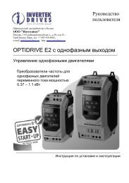
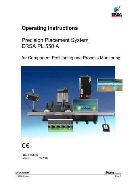
<strong>Operating</strong> <strong>Instructions</strong><br />
Precision Placement System<br />
ERSA PL 550 A<br />
for Component Positioning and Process Monitoring<br />
3BA00084-00<br />
Issued: 05/2002<br />
ERSA GmbH<br />
11.06.02.CI.ke.no Page 1
<strong>Operating</strong> <strong>Instructions</strong><br />
ERSA PL 550 A and PL 550 AU<br />
Thank you for deciding to purchase an ERSA PL 550 A Precision Positioning System.<br />
Your instrument was manufactured according to the highest quality standards and was tested<br />
before shipment. Operation is quite simple; nevertheless, we recommend carefully reading these<br />
<strong>Operating</strong> <strong>Instructions</strong> before using the camera for the first time. Please contact us if you have any<br />
further questions:<br />
ERSA GmbH<br />
ERSA GmbH<br />
Leonhard-Karl-Str. 24<br />
D-97877 Wertheim<br />
Germany<br />
Tel. ++49/9342 800 0<br />
Fax. ++49/9342 800 100<br />
e-mail info@ersa.de<br />
Web www.ersa.de<br />
11.06.02.we.no 3BA00084-00 PL 550A_e.doc Page 2
<strong>Operating</strong> <strong>Instructions</strong><br />
ERSA PL 550 A and PL 550 AU<br />
CONTENTS Page<br />
1 INTRODUCTION 4<br />
2 TECHNICAL DATA 4<br />
2.1 DIMENSIONS 4<br />
2.2 TECHNICAL OVERVIEW 5<br />
2.3 MONITOR SPECIFICATIONS 6<br />
3 SAFETY INSTRUCTIONS AND REMARKS 7<br />
4 STARTING OPERATION 8<br />
4.1 SCOPE OF DELIVERY 8<br />
4.2 POSITIONING THE IR 500 A / 550 A ON THE PL 550 A BASE PLATE 9<br />
4.3 PORTS AND CONTROLS 10<br />
4.3.1 BASIC UNIT PORTS 10<br />
4.3.2 VISIONBOX PORTS 10<br />
4.3.3 VACUUM PUMP PORT 11<br />
4.3.4 CONNECTION OF A WRIST GROUNDING STRAP 11<br />
4.4 SETTING UP THE CAMERA MODULE 12<br />
4.5 USE OF THE PRINTED CIRCUIT BOARD HOLDER 13<br />
4.6 SWITCHING ON THE SYSTEM 14<br />
4.7 CALIBRATING THE SYSTEM 15<br />
5 FUNCTIONAL DESCRIPTION 16<br />
5.1 OPERATION 16<br />
5.1.1 THE KEYBOARD 16<br />
5.1.2 ADJUSTING THE ZOOM 16<br />
5.1.3 ADJUSTING THE FOCUS 16<br />
5.1.4 USING THE CAM PRESET 17<br />
5.1.5 MOVING THE COMPONENT INSERTION HEAD AND ADJUSTING THE RPC<br />
ILLUMINATION 17<br />
5.2 PICK UP COMPONENTS 17<br />
5.3 OPERATING THE VISIONBOX 18<br />
5.4 ALIGNING THE COMPONENT 18<br />
5.5 CENTERING THE X-Y MICROMETER TABLE 19<br />
5.6 WORKING WITH THE OPTIONAL SPLIT OPTICAL SYSTEM CASSETTE 20<br />
5.7 AREAS OF APPLICATION OF THE REFLOW PROCESS CAMERA (RPC) 21<br />
5.8 APPLICATION EXAMPLES 21<br />
6 ERROR DIAGNOSIS AND CORRECTION 22<br />
7 MAINTENANCE AND CARE 23<br />
8 SPARE PARTS AND OPTIONS 23<br />
9 WARRANTY 24<br />
ERSA GmbH<br />
11.06.02.we.no 3BA00084-00 PL 550A_e.doc Page 3
<strong>Operating</strong> <strong>Instructions</strong><br />
ERSA PL 550 A and PL 550 AU<br />
1 INTRODUCTION<br />
ERSA GmbH<br />
The ERSA PL 550 A Precision Placement System allows the processing of multiposition<br />
SMT components for rework and component insertion. It also allows process monitoring<br />
during the processing of electronic components in engineering, production and repairs. The<br />
PL 550 A offers the utmost flexibility and easy handling. At the same time, the system is<br />
perfectly suited everyday use in production.<br />
The device can be combined with the Rework System IR 500 A or IR 550 A, set up directly<br />
on the base plate of the PL 550 A.<br />
2 TECHNICAL DATA<br />
2.1 DIMENSIONS<br />
Views of PL 550 A (without RPC camera module)<br />
11.06.02.we.no 3BA00084-00 PL 550A_e.doc Page 4
<strong>Operating</strong> <strong>Instructions</strong><br />
ERSA PL 550 A and PL 550 AU<br />
ERSA GmbH<br />
View of swivel area of the RPC camera module<br />
2.2 TECHNICAL OVERVIEW<br />
<strong>Operating</strong> temperature: 0 – 40 °C<br />
Relative humidity: 0 – 80 %<br />
NOTE: Avoid severe temperature variations. After changing the location of the<br />
device, acclimatize the device before starting operation again (at least 30<br />
minutes).<br />
Weight: approx. 21 kg<br />
Housing design antistatic<br />
Power supply for basic unit: 100 – 230 V, 50/60 Hz<br />
Component insertion force approx. 1.5 N (vacuum switching point)<br />
Component dimensions max. 40 x 40 mm<br />
Illumination LED row light (separately adjustable for component<br />
and PCB)<br />
LED ring light for RPC camera (adjustable)<br />
Performance data of the optical system and the cameras<br />
RPC opt. working distance ca. 200 mm<br />
Camera zoom 72 x (18 x optical, 4 x digital)<br />
Standard (CCIR) PAL composite (FBAS)<br />
Video out BNC / cinch<br />
White balance automatic<br />
Resolution 752 x 582 active pixels, > 460 TV lines<br />
Min. sensitivity 3 lx (F1.4)<br />
11.06.02.we.no 3BA00084-00 PL 550A_e.doc Page 5
<strong>Operating</strong> <strong>Instructions</strong><br />
ERSA PL 550 A and PL 550 AU<br />
2.3 MONITOR SPECIFICATIONS<br />
ERSA GmbH<br />
For optimal operation of the system, we recommend using a monitor with the following<br />
minimal specifications (monitor not included with delivery):<br />
Horizontal resolution > 460 TV lines<br />
Monitor type color tube monitor (black & white not recommended)<br />
or PC monitor (with framegrabber)<br />
or flat screen<br />
Signal type PAL composite (FBAS)<br />
Required terminal cinch<br />
NOTE: Use of a monitor with inferior quality will directly affect the image quality and<br />
thereby limit the display quality for small components.<br />
NOTE: For displaying live images on a PC and for managing image data, use the<br />
software package ERSA IDView (order number 0VSID100).<br />
11.06.02.we.no 3BA00084-00 PL 550A_e.doc Page 6
<strong>Operating</strong> <strong>Instructions</strong><br />
ERSA PL 550 A and PL 550 AU<br />
3 SAFETY INSTRUCTIONS AND REMARKS<br />
ERSA GmbH<br />
Safety-related notes in these <strong>Operating</strong> <strong>Instructions</strong> are indicated as follows:<br />
ATTENTION:<br />
Be sure to follow these instructions.<br />
Notes are indicated by<br />
NOTE:<br />
ATTENTION:<br />
Open the device only if the power plug has been completely disconnected<br />
from the supply network.<br />
Repairs may be performed only by experienced and qualified electricians.<br />
The device contains active parts.<br />
There is a risk of fatal injury if inexperienced people work on the unit.<br />
ATTENTION: The component insertion head is motor-driven! Do not reach into the area of<br />
motion of the component insertion head. Risk of hand injury!<br />
NOTE:<br />
The PL 550 A Positioning System is a sensitive and precise optical<br />
instrument. Always handle the device with the utmost care.<br />
Alterations on this device will render the warranty void and can affect<br />
the functioning of the equipment.<br />
11.06.02.we.no 3BA00084-00 PL 550A_e.doc Page 7
<strong>Operating</strong> <strong>Instructions</strong><br />
ERSA PL 550 A and PL 550 AU<br />
4 STARTING OPERATION<br />
4.1 SCOPE OF DELIVERY<br />
ERSA GmbH<br />
The ERSA PL 550 A is supplied with the following components:<br />
� Basic unit (complete with controller, vacuum component insertion head, X-Y micrometer<br />
table, Visonbox with integrated camera)<br />
� Printed circuit board holder (mounted on the X-Y micrometer table)<br />
� External vacuum pump (115 V or 230V version)<br />
� Two vacuum suctioners (4 mm and 10 mm in diameter)<br />
� External keyboard<br />
� Video connecting cable (cinch / cinch)<br />
� Three Allen wrenches<br />
� Calibrating pin with calibrating plate<br />
� <strong>Operating</strong> <strong>Instructions</strong><br />
Options:<br />
� Reflow Process Camera, RPC camera module (order number 0VSRPC-UKIT) with<br />
integrated LED ring light mounted on a swivel arm<br />
- included with order number 0PL550A<br />
- not included with order number 0PL550AU<br />
� Split optical system cassette (order number 0PL500A-SPC)<br />
Before unpacking, please check the packaging for visible signs of damage during transport.<br />
If there is such damage, immediately notify the carrier and enter a remark on the delivery<br />
note.<br />
The system is supplied according to the ordered configuration. Place the basic unit on a<br />
solid, level table with sufficient space at the rear and sides of the device.<br />
11.06.02.we.no 3BA00084-00 PL 550A_e.doc Page 8
<strong>Operating</strong> <strong>Instructions</strong><br />
ERSA PL 550 A and PL 550 AU<br />
4.2 POSITIONING THE IR 500 A / 550 A ON THE PL 550 A BASE PLATE<br />
ERSA GmbH<br />
The left side of the base plate contains supports that can be individually unscrewed. Place<br />
the IR 500 A or IR 550 A Rework System on the base plate and connect the system<br />
according to the <strong>Operating</strong> <strong>Instructions</strong>.<br />
The supports can be separately mounted in order to set the Rework System at either of<br />
three possible heights. Select the height suitable for your application.<br />
ERSA<br />
IR 500 A or IR 550 A<br />
Support of the<br />
PL 550 A<br />
Bases of the<br />
IR 500 A or IR 550 A<br />
Base plate PL 550 A<br />
11.06.02.we.no 3BA00084-00 PL 550A_e.doc Page 9
<strong>Operating</strong> <strong>Instructions</strong><br />
ERSA PL 550 A and PL 550 AU<br />
4.3 PORTS AND CONTROLS<br />
The following ports are located on the rear of the device:<br />
4.3.1 BASIC UNIT PORTS<br />
� Monitor port, BNC (Video Out)<br />
� Camera port of the Visionbox, cinch (Video1 In)<br />
� Camera port for RPC, cinch (Video2 In)<br />
� Voltage supply for component insertion head (24 V DC)<br />
� Port for component insertion head cable (yellow arrow)<br />
� Voltage supply for Visionbox (12 V DC)<br />
� Power switch (On / Off)<br />
� Power supply / power cable port (100-240 VAC)<br />
� Connecting socket for vacuum pump (Vacuumpump)<br />
ERSA GmbH<br />
View of connected device:<br />
4.3.2 VISIONBOX PORTS<br />
The following ports are located on the rear of the Visionbox:<br />
� Port for camera control port going to component insertion<br />
arm (1)<br />
� Camera signal going to "Video1 In" (2)<br />
� Voltage supply going to "12 V DC" (3)<br />
NOTE: The RS 232 plug-in connection is not used during<br />
operation. It is used to calibrate the camera during<br />
production.<br />
11.06.02.we.no 3BA00084-00 PL 550A_e.doc Page 10<br />
1<br />
2 3
<strong>Operating</strong> <strong>Instructions</strong><br />
ERSA PL 550 A and PL 550 AU<br />
� Control cable and supply voltage for component<br />
insertion head (1)<br />
� Port for control line for RPC camera module (2)<br />
� Port for external keyboard (3)<br />
� Port for camera control coming from Visionbox (4)<br />
ERSA GmbH<br />
ATTENTION: Check whether the supply voltage lies in the range indicated on the rating<br />
plate.<br />
4.3.3 VACUUM PUMP PORT<br />
The vacuum is generated by an external vacuum pump. To prevent vibrations during<br />
component insertion, we recommend placing the pump away from the device or below the<br />
table. The pump is switched on and off together with the system when the power supply is<br />
directly connected to the PL 550 A component insertion system.<br />
Switching on the vacuum pump (1)<br />
Setting the vacuum power from 50 to 100% (2)<br />
Simply insert the vacuum hose (small) in the large<br />
hose. Connect the large hose to the hose connector<br />
on the pump (3).<br />
NOTE: Delivery includes an air filter that can be used as required in the larger hose.<br />
4.3.4 CONNECTION OF A WRIST GROUNDING STRAP<br />
For safety purposes you can connect a wrist<br />
grounding strap directly to the device.<br />
11.06.02.we.no 3BA00084-00 PL 550A_e.doc Page 11<br />
3<br />
1<br />
1 2<br />
3 4<br />
2
<strong>Operating</strong> <strong>Instructions</strong><br />
ERSA PL 550 A and PL 550 AU<br />
4.4 SETTING UP THE CAMERA MODULE<br />
ERSA GmbH<br />
The RPC camera module (only included with order number 0PL550A) is premounted on a<br />
swiveling arm. Use the arm fixing screw located on the bottom side of the device to adjust<br />
the force needed to swivel the camera.<br />
NOTE: The RPC-UKIT includes instructions on attaching the camera to the system.<br />
The height and perspective of the camera module itself can be changed by means of the<br />
crosshead clamp, so that you can quickly set the optimal viewing angle for each application.<br />
For applications requiring a direct view of the soldering joints (as with BGA balls), we<br />
recommend setting the camera in the forward viewing direction.<br />
The camera module contains an LED ring light, whose brightness can be adjusted at the<br />
external keyboard.<br />
The LED lighting is distinguished by a very long lifetime and very high color temperature,<br />
which varies little as the brightness is changed. The user thus receives images without<br />
color distortions under all lighting conditions.<br />
11.06.02.we.no 3BA00084-00 PL 550A_e.doc Page 12
<strong>Operating</strong> <strong>Instructions</strong><br />
ERSA PL 550 A and PL 550 AU<br />
4.5 USE OF THE PRINTED CIRCUIT BOARD HOLDER<br />
ERSA GmbH<br />
The PCB holder is separately packaged and located<br />
under the basic system. It must first be mounted.<br />
Carefully remove the PCB holder from the packaging and<br />
remove the stop screw on one side.<br />
Hold the rail (1) so that the two movable PCB holders<br />
face upwards.<br />
Carefully slide the rail into the roller guide. You'll notice<br />
slight resistance due to the pretension set by the<br />
manufacturer.<br />
Press through this resistance and slide the rail completely<br />
in.<br />
A fixing screw (2) is located on the front side.<br />
We recommend always tightening this screw during the rework, to prevent accidental<br />
displacements.<br />
SETTING UP<br />
When setting up the device we recommend moving the two<br />
sliding PCB holders approximately to the middle of the rail.<br />
To move the PCB holders, open the two black fixing<br />
on the top.<br />
A fixing screw prevents accidental movement during<br />
soldering.<br />
The two PCB fixing rails can be moved. The right side has<br />
additional springs for clamping the board during work.<br />
11.06.02.we.no 3BA00084-00 PL 550A_e.doc Page 13<br />
1<br />
2
<strong>Operating</strong> <strong>Instructions</strong><br />
ERSA PL 550 A and PL 550 AU<br />
ERSA GmbH<br />
The PCB can then be moved<br />
from the front and pulled out.<br />
NOTE: Do not push the right rail too much against the PCB edge, to enable easy<br />
sliding from the front.<br />
4.6 SWITCHING ON THE SYSTEM<br />
An ON/OFF switch is located on the back of the device (right). Switch on the unit after<br />
previously connecting it to a monitor.<br />
Make sure that the device is correctly connected and that the vacuum pump is running.<br />
After switching on, press the Head / Light ↑<br />
button to move the component insertion head to<br />
the upper position<br />
ATTENTION: The component insertion head is motor-driven! Do not reach into the area of<br />
motion of the component insertion head. Risk of hand injury!<br />
Then adjust the RPC camera module according your application.<br />
Use the external keyboard for zooming and focusing.<br />
NOTE: The device should be at room temperature before being used.<br />
11.06.02.we.no 3BA00084-00 PL 550A_e.doc Page 14
<strong>Operating</strong> <strong>Instructions</strong><br />
ERSA PL 550 A and PL 550 AU<br />
4.7 CALIBRATING THE SYSTEM<br />
ERSA GmbH<br />
The positioning system was calibrated and adjusted in the factory. Vibrations occurring<br />
during transport may make recalibration necessary during installation, however. The same<br />
procedure can also be used to check the device at regular intervals.<br />
The aim of the calibration is to match the optical axis to the mechanical axis.<br />
A. CHECKING THE SYSTEM<br />
1. Insert the calibrating plate in the PCB holder<br />
2. Mount the calibrating needle on the Z-axis<br />
3. Move the component insertion head downwards using the<br />
motor<br />
4. Slowly lower the calibrating needle into the hole in the<br />
calibrating plate. Use the X-Y micrometer table to achieve an<br />
an exact fit. The needle must be able to move up and down in<br />
the hole completely freely.<br />
5. Move the component insertion head upwards using the<br />
motor drive<br />
6. Check the image in the monitor. If the image does not<br />
appear like that labeled "GOOD" on the right, you have to<br />
recalibrate the system.<br />
POOR GOOD<br />
B. RECALIBRATION<br />
1. Open the screws (1) of the Visionbox brackets on<br />
both sides.<br />
2. Two Allen screws (2) are located on top for the fine<br />
adjustment. These screws allow the Visionbox to be<br />
adjusted until the monitor displays an image like that<br />
labeled "GOOD" above.<br />
3. Now tighten the fixing screws.<br />
4. Repeat the test procedure as described under A.<br />
NOTE: It may be necessary to screw in or unscrew the Allen screws alternately in<br />
order to achieve the fit.<br />
Use the supplied Allen wrench for loosening and tightening the screws.<br />
11.06.02.we.no 3BA00084-00 PL 550A_e.doc Page 15<br />
2<br />
1
<strong>Operating</strong> <strong>Instructions</strong><br />
ERSA PL 550 A and PL 550 AU<br />
5 FUNCTIONAL DESCRIPTION<br />
The ERSA Precision Placement System PL 550 A was developed for use with ERSA<br />
IR Rework Systems. It allows ultra-precise component positioning and process monitoring<br />
during soldering, and thus provides the optimal supplement to an IR rework system.<br />
5.1 OPERATION<br />
5.1.1 THE KEYBOARD<br />
ERSA GmbH<br />
All electrical functions on the PL 550 A are conveniently controlled at an external keyboard.<br />
Connect the keyboard at the back of the device.<br />
The keyboard is used for both cameras, the integrated camera of the Visionbox and the<br />
optional Reflow Process Camera (RPC).<br />
The individual functions are explained below.<br />
5.1.2 ADJUSTING THE ZOOM<br />
Adjusting the zoom of the selected camera<br />
Adjusting the focus of the selected camera<br />
Selecting preset zoom settings<br />
Raising and lowering the component insertion head<br />
and adjusting the brightness of the LED ring light<br />
Use the Zoom + and Zoom – buttons to adjust the zoom range of the cameras. For greater<br />
enlargements the camera image is internally enlarged digitally. This can diminish the image<br />
quality.<br />
The adjusted zoom ranges are retained even after the unit is switched off, and are available<br />
when it is switched on again.<br />
5.1.3 ADJUSTING THE FOCUS<br />
Use the Focus + and Focus – buttons to adjust the given camera's focus to the given<br />
working position.<br />
If you cannot focus a particular image, then the object is located outside the working range<br />
of the camera.<br />
11.06.02.we.no 3BA00084-00 PL 550A_e.doc Page 16
<strong>Operating</strong> <strong>Instructions</strong><br />
ERSA PL 550 A and PL 550 AU<br />
5.1.4 USING THE CAM PRESET<br />
ERSA GmbH<br />
Besides the continuously variable zoom adjustment with the Zoom + and Zoom – buttons,<br />
two predefined zoom settings are also available on each camera. The zoom settings are<br />
attained using the Cam Preset 1 and Cam Preset 2 buttons.<br />
These zoom settings allow the user to change quickly between an overview display and a<br />
detailed view without having to adjust the complete zoom range manually.<br />
5.1.5 MOVING THE COMPONENT INSERTION HEAD AND ADJUSTING THE RPC<br />
ILLUMINATION<br />
Use the Head / Light ↑ and Head / Light ↓ buttons to raise and lower the component<br />
insertion head and to regulate the integrated LED ring light of the camera module. In this<br />
way you can adapt the light intensity to any application.<br />
Change the function by double-clicking (briefly pressing twice) the Head / Light ↑ button<br />
with the Visionbox pushed back (RPC camera enabled).<br />
5.2 PICK UP COMPONENTS<br />
Place the component to be positioned in the<br />
component tray and align it using the grid that has<br />
been moved up.<br />
Center the component tray and component under<br />
the component insertion head (monitoring with the<br />
Visionbox) and then lower the component insertion<br />
head using the motor. (Head / Light ↓ button)<br />
NOTE: For safety reasons keep the given button pressed during the entire lowering or<br />
raising movement.<br />
11.06.02.we.no 3BA00084-00 PL 550A_e.doc Page 17
<strong>Operating</strong> <strong>Instructions</strong><br />
ERSA PL 550 A and PL 550 AU<br />
Manually lower the vacuum needle by turning the<br />
positioning rotary knob (1).<br />
As soon as the green LED on the positioning head<br />
lights up, the vacuum automatically switches on<br />
and the component can be raised.<br />
Use the Head / Light ↑ button to move the<br />
component insertion head upwards by motor again.<br />
NOTE: Depending on the component height, you may have to adjust the mounting<br />
height of the suctioner at the Z-axis. Use the Allen wrench supplied for this<br />
purpose.<br />
5.3 OPERATING THE VISIONBOX<br />
To align the component over the landing area of<br />
the PCB, pull the Visionbox at the handle (1) into<br />
the front position. The system then switches to<br />
"Video 1 In" and the image of the Visionbox<br />
appears on the monitor.<br />
Turn the knob (2) to adjust the red LED illumination<br />
for the underside of the components.<br />
The rotary knob for illuminating the upper side of the PCB is located on the opposite side of<br />
the Visionbox.<br />
5.4 ALIGNING THE COMPONENT<br />
The component illuminated from<br />
below can now be aligned in<br />
advance at the grid. The angle is<br />
adjusted using the rotation<br />
rotary knob. (1)<br />
Now slide the PCB under the Visionbox until there is an optical superposition of the<br />
component underside and the landing areas on the PCB.<br />
ERSA GmbH<br />
11.06.02.we.no 3BA00084-00 PL 550A_e.doc Page 18<br />
1<br />
1<br />
1<br />
2
<strong>Operating</strong> <strong>Instructions</strong><br />
ERSA PL 550 A and PL 550 AU<br />
Following this coarse alignment fix the PCB holder with the clamping screw (see 4.5).<br />
Bring the two planes into the<br />
camera's focus by manually<br />
lowering the component.<br />
The grid dimensions of landing<br />
area and component must<br />
match.<br />
Now bring the component and<br />
landing areas into coincidence by<br />
adjusting the position of the PCB<br />
by means of the two micrometer<br />
screws (X and Y).<br />
NOTE: When positioning BGA components, you can further enlarge the center of the<br />
component by means of the zoom, to monitor the position.<br />
5.5 CENTERING THE X-Y MICROMETER TABLE<br />
We recommend re-centering the micrometer table after<br />
each time it is used. You will then always the maximum<br />
travel distance at your disposal.<br />
The red rings on the micrometer adjusters indicate the<br />
center positions.<br />
For a more precise alignment, simply position the<br />
component tray with the crosshair at the center of the<br />
camera and align the X-Y table with the crosshair.<br />
ERSA GmbH<br />
X Y<br />
11.06.02.we.no 3BA00084-00 PL 550A_e.doc Page 19
<strong>Operating</strong> <strong>Instructions</strong><br />
ERSA PL 550 A and PL 550 AU<br />
5.6 WORKING WITH THE OPTIONAL SPLIT OPTICAL SYSTEM CASSETTE<br />
Use the Split Optical System Cassette (1) to process<br />
larger fine-pitch components.<br />
The Split Optical System Cassette is an ultra-precise<br />
device allowing two opposite corners of a component to<br />
be displayed greatly enlarged.<br />
Because of the laws of optics, however, only one part of<br />
the component can be made visible.<br />
(Order number 0PL500A-SPC)<br />
ATTENTION: Use the necessary caution when handling the Split Optical System Cassette.<br />
CAUTION – GLASS!<br />
The cassette is inserted in the system instead of the<br />
standard aperture plate.<br />
To remove the aperture plate, first loosen the fixing<br />
screw (2) on the left side of the Visionbox.<br />
Then cautiously remove the aperture plate from the slot.<br />
The Visionbox must be positioned so that the aperture<br />
cassette can be lifted out.<br />
Insert the Split Optical System Cassette instead, with the<br />
designation “Front” forwards.<br />
Fix the cassette in place again.<br />
NOTE: Depending on the design, you can use the Split Optical System Cassette to<br />
process only square components.<br />
ERSA GmbH<br />
11.06.02.we.no 3BA00084-00 PL 550A_e.doc Page 20<br />
2<br />
1
<strong>Operating</strong> <strong>Instructions</strong><br />
ERSA PL 550 A and PL 550 AU<br />
5.7 AREAS OF APPLICATION OF THE REFLOW PROCESS CAMERA (RPC)<br />
Depending on the case at hand, the RPC camera module can be used for the following<br />
visual tasks:<br />
Process visualization<br />
ERSA GmbH<br />
� Live monitoring of the rework soldering process with an ERSA IR Rework System<br />
� Recording of the process in combination with IDView.<br />
Soldering joint visualization<br />
� Performance of manual soldering operations with camera support<br />
� Dispensing of solder paste with camera support<br />
� Positioning of components with camera support<br />
Soldering joint inspection<br />
� Monitoring and documentation of soldering joints<br />
� Monitoring and documentation of solder paste printing<br />
NOTE: For displaying live images on a PC and for recording and managing image<br />
data, use the software package ERSA IDView (order number 0VSID100).<br />
5.8 APPLICATION EXAMPLES<br />
For documenting and evaluating inspection photos we recommend the<br />
software package ImageDoc (order number 0VSFG100)<br />
Process visualization on a PBGA:<br />
PBGA viewed from above PBGA before melt<br />
11.06.02.we.no 3BA00084-00 PL 550A_e.doc Page 21
<strong>Operating</strong> <strong>Instructions</strong><br />
ERSA PL 550 A and PL 550 AU<br />
ERSA GmbH<br />
Process visualization on a µBGA Process visualization on a flip chip<br />
6 ERROR DIAGNOSIS AND CORRECTION<br />
Despite the careful manufacture and quality control of the systems, errors and problems<br />
may arise during operation of the ERSA PL 550 A. Below we describe the procedure for<br />
diagnosing and correcting errors.<br />
NOTE: Do not place the IR system together with the PL 550 A in front of a window or<br />
near an intense light source, since external light can negatively affect the<br />
image quality.<br />
The component cannot be precisely positioned<br />
� Calibrate the system (see section 4.7).<br />
The image cannot be focused<br />
The viewed object is either too far from or too near the camera lens.<br />
� Change the distance between the object and the camera and try again to focus with the<br />
Focus + and Focus – buttons.<br />
� Clean the camera lenses.<br />
The image colors are wrong or brightness/contrast is less than optimal<br />
� Check the settings on your monitor or PC. If necessary, also check the image<br />
parameters of the ERSA IDView software.<br />
The Reflow Process Camera does not function / or there is no image<br />
No image on the monitor:<br />
� Check the plug-in video connection between the camera module and the basic unit and<br />
between the basic unit and the monitor. (If possible, set up a direct connection between the<br />
camera module and the monitor).<br />
The LED ring light remains dark and no image is displayed on the monitor:<br />
� Also check the plug-in connection of the voltage supply between the camera module and<br />
the basic unit.<br />
In case of other errors, contact your supplier or ERSA.<br />
11.06.02.we.no 3BA00084-00 PL 550A_e.doc Page 22
<strong>Operating</strong> <strong>Instructions</strong><br />
ERSA PL 550 A and PL 550 AU<br />
7 MAINTENANCE AND CARE<br />
ERSA GmbH<br />
Make sure that the optical components of the camera module are free of dirt and grease.<br />
NOTE: Use only genuine ERSA expendable and spare parts to maintain reliable<br />
functioning and the warranty.<br />
Depending on the degree of soiling, perform the following maintenance operations:<br />
� Using a moist cloth and mild household cleaner, remove solder paste and flux residue as<br />
well as dust from the system.<br />
� Clean the camera lens and the beam splitter of the Visionbox using the Optical System<br />
Cleaning Kit (0VSLC100).<br />
� Clean the guide rods of the component insertion head and the guide rails of the PCB with a<br />
slightly oiled cloth.<br />
� Regularly check the mobility of the rack and pinion drive at the component insertion head<br />
and if necessary re-grease the rack and pinion.<br />
8 SPARE PARTS AND OPTIONS<br />
0PL500A-S00.8 Vacuum suctioner, 0.8 mm diameter<br />
0PL500A-S01.2 Vacuum suctioner, 1.2 mm diameter<br />
0PL500A-S003 Vacuum suctioner, 3 mm diameter<br />
0PL500A-S004 Vacuum suctioner, 4 mm diameter<br />
0PL500A-S010 Vacuum suctioner, 10 mm diameter<br />
0PL500A-SPC Split Optical System Cassette<br />
0VSRPC-UKIT Reflow Process Camera Upgrade Kit (camera module with swivel<br />
arm)<br />
0PL500A-VB Visionbox<br />
0VSRPC555R RPC * LED PCB ring light<br />
0VSRPC550A-DP RPC * dimmerprint<br />
0PL500A-MA01 Motor drive complete with plugs<br />
0PL505A Control electronics for motor drive (insertable from the rear)<br />
0PL505 Control electronics for Visionbox<br />
0PL505B Control electronics for vacuum<br />
0PL505C Power electronics<br />
0PL504 Vacuum pump, 220 – 230 V<br />
0PL504-A Vacuum pump, 100 -110 V<br />
0PL500A-TA01 Keyboard with cable<br />
0PL500A-MK01 Video cable PL 500 A – monitor (BNC/cinch-cinch)<br />
0PL500A-KS01 Calibration set, complete (calibrating plate with needle)<br />
0PL500A-BA Component tray<br />
0PL500A-LP01 Printed circuit board support<br />
0VSLC100 Optical system cleaning kit<br />
Software packages<br />
0VSID100 ID View Image Explorer (with framegrabber)<br />
0VSFG100 ImageDoc software (with framegrabber)<br />
* In case these parts become defective, we recommend completely exchanging the RPC camera<br />
(0VSRPC-UKIT) if necessary<br />
11.06.02.we.no 3BA00084-00 PL 550A_e.doc Page 23
<strong>Operating</strong> <strong>Instructions</strong><br />
ERSA PL 550 A and PL 550 AU<br />
9 WARRANTY<br />
ERSA GmbH<br />
The warranty period corresponds to the General Terms of Sales Deliveries and Payment of<br />
ERSA GmbH.<br />
The ERSA GmbH can accept warranty claims only if the device is returned in the original<br />
packaging.<br />
These <strong>Operating</strong> <strong>Instructions</strong> were produced with the utmost care. Nevertheless, we cannot<br />
provide any guarantee for the content, completeness or quality of the information contained<br />
in this manual. The content is being continually updated and adapted to current conditions.<br />
All the data contained in these <strong>Operating</strong> <strong>Instructions</strong>, including specifications of products<br />
and procedures, have been obtained in good conscience and using the latest technical<br />
equipment. These specifications are provided without obligation and do not discharge the<br />
user from the responsibility of conducting an inspection before using the device. We accept<br />
no responsibility for violations of the industrial property rights of third parties or for<br />
applications and procedures that we have not previously expressly approved in writing.<br />
We reserve the right to make technical changes in the interest of product improvement.<br />
Within the bounds of legal possibility, liability for direct damage, consequential damage and<br />
third party damage resulting from the acquisition of this product is excluded.<br />
All rights reserved. This manual may not be reproduced, transmitted or in translated in<br />
another language, even in excerpt form, without the written permission of ERSA GmbH.<br />
We reserve the right to make technical changes in the interest of product improvement.<br />
11.06.02.we.no 3BA00084-00 PL 550A_e.doc Page 24