
Create successful ePaper yourself
Turn your PDF publications into a flip-book with our unique Google optimized e-Paper software.
<strong>Operating</strong> <strong>Instructions</strong><br />
ERSA PL 550 A and PL 550 AU<br />
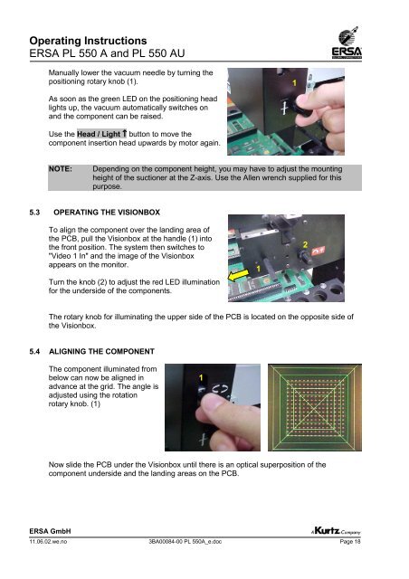
Manually lower the vacuum needle by turning the<br />
positioning rotary knob (1).<br />
As soon as the green LED on the positioning head<br />
lights up, the vacuum automatically switches on<br />
and the component can be raised.<br />
Use the Head / Light ↑ button to move the<br />
component insertion head upwards by motor again.<br />
NOTE: Depending on the component height, you may have to adjust the mounting<br />
height of the suctioner at the Z-axis. Use the Allen wrench supplied for this<br />
purpose.<br />
5.3 OPERATING THE VISIONBOX<br />
To align the component over the landing area of<br />
the PCB, pull the Visionbox at the handle (1) into<br />
the front position. The system then switches to<br />
"Video 1 In" and the image of the Visionbox<br />
appears on the monitor.<br />
Turn the knob (2) to adjust the red LED illumination<br />
for the underside of the components.<br />
The rotary knob for illuminating the upper side of the PCB is located on the opposite side of<br />
the Visionbox.<br />
5.4 ALIGNING THE COMPONENT<br />
The component illuminated from<br />
below can now be aligned in<br />
advance at the grid. The angle is<br />
adjusted using the rotation<br />
rotary knob. (1)<br />
Now slide the PCB under the Visionbox until there is an optical superposition of the<br />
component underside and the landing areas on the PCB.<br />
ERSA GmbH<br />
11.06.02.we.no 3BA00084-00 PL 550A_e.doc Page 18<br />
1<br />
1<br />
1<br />
2