TDS 261 Standard Jamb Construction for Rolling Steel Fire Doors
TDS 261 Standard Jamb Construction for Rolling Steel Fire Doors
TDS 261 Standard Jamb Construction for Rolling Steel Fire Doors

Create successful ePaper yourself
Turn your PDF publications into a flip-book with our unique Google optimized e-Paper software.
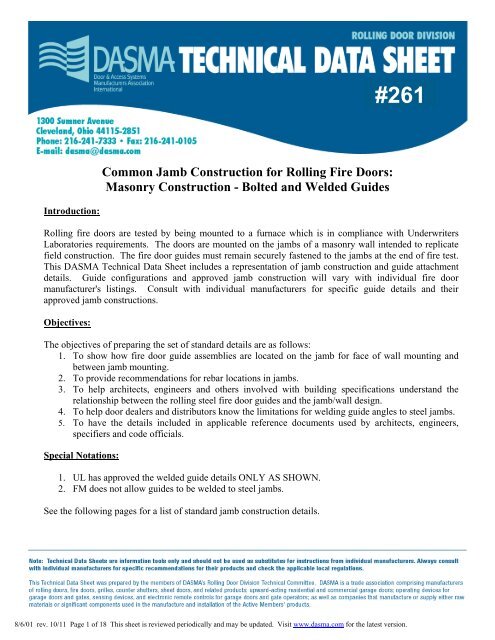
#<strong>261</strong>Common <strong>Jamb</strong> <strong>Construction</strong> <strong>for</strong> <strong>Rolling</strong> <strong>Fire</strong> <strong>Doors</strong>:Masonry <strong>Construction</strong> - Bolted and Welded GuidesIntroduction:<strong>Rolling</strong> fire doors are tested by being mounted to a furnace which is in compliance with UnderwritersLaboratories requirements. The doors are mounted on the jambs of a masonry wall intended to replicatefield construction. The fire door guides must remain securely fastened to the jambs at the end of fire test.This DASMA Technical Data Sheet includes a representation of jamb construction and guide attachmentdetails. Guide configurations and approved jamb construction will vary with individual fire doormanufacturer's listings. Consult with individual manufacturers <strong>for</strong> specific guide details and theirapproved jamb constructions.Objectives:The objectives of preparing the set of standard details are as follows:1. To show how fire door guide assemblies are located on the jamb <strong>for</strong> face of wall mounting andbetween jamb mounting.2. To provide recommendations <strong>for</strong> rebar locations in jambs.3. To help architects, engineers and others involved with building specifications understand therelationship between the rolling steel fire door guides and the jamb/wall design.4. To help door dealers and distributors know the limitations <strong>for</strong> welding guide angles to steel jambs.5. To have the details included in applicable reference documents used by architects, engineers,specifiers and code officials.Special Notations:1. UL has approved the welded guide details ONLY AS SHOWN.2. FM does not allow guides to be welded to steel jambs.See the following pages <strong>for</strong> a list of standard jamb construction details.8/6/01 rev. 10/11 Page 1 of 18 This sheet is reviewed periodically and may be updated. Visit www.dasma.com <strong>for</strong> the latest version.
#<strong>261</strong>DASMA Recommended<strong>Standard</strong> <strong>Jamb</strong><strong>Construction</strong>:<strong>Rolling</strong> <strong>Fire</strong> <strong>Doors</strong>On Masonry WallsBolted and Welded GuidesGeneral Notes:1. Existing and new wall construction covered2. Details are <strong>for</strong> general in<strong>for</strong>mation only3. Consult a structural engineer <strong>for</strong> actual wall construction4. Details are attachments to <strong>TDS</strong>-<strong>261</strong>8/6/01 rev. 10/11 Page 2 of 18 This sheet is reviewed periodically and may be updated. Visit www.dasma.com <strong>for</strong> the latest version.
#<strong>261</strong>Figure 1.Figure 2.Figure 3.Figure 4.Figure 5.Figure 6.Figure 7.Figure 8.Figure 9.List of <strong>Standard</strong> <strong>Jamb</strong> <strong>Construction</strong> Details(<strong>Rolling</strong> <strong>Fire</strong> <strong>Doors</strong>: Masonry <strong>Construction</strong> - Bolted and Welded Guides)Preferred CMU Rein<strong>for</strong>cement DetailPreferred Brick/Concrete Rein<strong>for</strong>cement DetailFace-mounted “Z” guide configuration; bolted connection; hollow blockFace-mounted “Z” guide configuration; bolted connection; filled blockFace-mounted “Z” guide configuration; bolted connection; brick or poured concreteFace-mounted “E” guide configuration; fastened or welded connection; steel bent plate at jamb; brick or pouredconcreteFace-mounted “E” guide configuration; fastened or welded connection; steel angle at jamb; brick or pouredconcreteFace-mounted “E” guide configuration; fastened or welded connection; structural steel channel at jamb; brick orpoured concreteFace-mounted “E” guide configuration; fastened or welded connection; steel angle at jamb; filled blockFigure 10. <strong>Jamb</strong>-mounted “Z” guide configuration; bolted connection; filled blockFigure 11. <strong>Jamb</strong>-mounted “Z” guide configuration; bolted connection; brick or poured concreteFigure 12. <strong>Jamb</strong>-mounted “Z” guide configuration; fastened or welded connection; structural steel channel at jamb; brick orpoured concreteFigure 13. <strong>Jamb</strong>-mounted “Z” guide configuration; fastened or welded connection; steel bent plate at jamb; brick or pouredconcreteFigure 14. Section view, face-mounted welded guide wall angleFigure 15. Section view, jamb-mounted welded guide wall angle8/6/01 rev. 10/11 Page 3 of 18 This sheet is reviewed periodically and may be updated. Visit www.dasma.com <strong>for</strong> the latest version.
#<strong>261</strong>Figure 12" (max.)Rebar, TypicalCMU filled with min. 2500 psi Concrete2" (max.)2" (max.)Figure 1Preferred CMU Rein<strong>for</strong>cement Detail8/6/01 rev. 10/11 Page 4 of 18 This sheet is reviewed periodically and may be updated. Visit www.dasma.com <strong>for</strong> the latest version.
#<strong>261</strong>Rebar, Typical (in Concrete)2" (max.) Brick, or min. 2500 psi Concrete (shown)2" (max.)Rebar, Typical2" (max.)recommendedmin. 10" horiz. reinf. free zoneFigure 2Preferred Brick/Concrete Rein<strong>for</strong>cement Detail8/6/01 rev. 10/11 Page 5 of 18 This sheet is reviewed periodically and may be updated. Visit www.dasma.com <strong>for</strong> the latest version.
#<strong>261</strong>Figure 3Crush Plate, or equivalentUnfilled BlockMin. 3/8" Dia. Threaded RodFigure 3Face-mounted "Z" configuration;bolted connection; hollow block8/6/01 rev. 10/11 Page 6 of 18 This sheet is reviewed periodically and may be updated. Visit www.dasma.com <strong>for</strong> the latest version.
#<strong>261</strong>Rebar, TypicalCMU Filled with min. 2500 psi Concrete8 x Bolt Dia. (min.)Min. 3/8" Dia. Fasteners6 x Bolt Dia. (min.)Figure 4Face-mounted "Z" configuration;bolted connection; filled blockFigure 48/6/01 rev. 10/11 Page 7 of 18 This sheet is reviewed periodically and may be updated. Visit www.dasma.com <strong>for</strong> the latest version.
#<strong>261</strong>Brick, or min. 2500 psiConcrete (shown)Rebar, Typ., See Figure 28 x Bolt Dia. (min.)Min. 3/8" Dia.Fasteners6 x Bolt Dia.(min.)Figure 5Face-mounted "Z" configuration;bolted connection; brick or concrete8/6/01 rev. 10/11 Page 8 of 18 This sheet is reviewed periodically and may be updated. Visit www.dasma.com <strong>for</strong> the latest version.
#<strong>261</strong>2-1/2" (min.)Brick, or min. 2500 psiConcrete (shown)Min. 3/16" ThickBent Plate withWelded Studs orequivalent, by othersRebar, Typ., See Figure 2Min. 3/8" Dia. Fastenersor Weld* as shown inSection A-A, Figure 14.* UL listed products onlyNotes:1. For doors mounted to a steel plate member,this plate member must be embedded, orsecured to the masonry wall. Plate must bedesigned to have an expansion gap equal to 1/8"<strong>for</strong> each foot of opening height in order to besuitable <strong>for</strong> welding guide angle to jamb.2. For doors mounted to steel, when this steelstops at the header, metal shims must beinserted between the guide wall angle and thewall above the opening.Figure 6Face-mounted "E" configuration;fastened or welded connection; steel bent plate at jamb;brick or concrete8/6/01 rev. 10/11 Page 9 of 18 This sheet is reviewed periodically and may be updated. Visit www.dasma.com <strong>for</strong> the latest version.
#<strong>261</strong>2 1/2"Brick, or min. 2500 psiConcrete (shown)Min. 3/16" Thick<strong>Steel</strong> Angle, withWelded Studs or equivalent,by othersMin. 3/8" Dia. Fastenersor Weld* as shown inSection A-A, Figure 14.* UL listed products onlyNote: For doors mounted to a steel angle, thisangle must be embedded, or secured to themasonry wall. Angle must be designed to havean expansion gap equal to 1/8" <strong>for</strong> each foot ofopening height in order to be suitable <strong>for</strong>welding guide angle to jamb.Figure 7Face-mounted "E" configuration;fastened or welded connection; steel angle at jamb;brick or concrete8/6/01 rev. 10/11 Page 10 of 18 This sheet is reviewed periodically and may be updated. Visit www.dasma.com <strong>for</strong> the latest version.
#<strong>261</strong>2-1/2" (min.)Min. 3/16" ThickStructural <strong>Steel</strong> Channel, withWelded Studs or equivalent,by othersBrick, or min. 2500 psiConcrete (shown)Min. 3/8" Dia. Fastenersor Weld* as shown inSection A-A, Figure 14.* UL listed products onlyNotes:1. For doors mounted to a steel channel, thischannel must be embedded, or secured to themasonry wall. Channel must be designed tohave an expansion gap equal to 1/8" <strong>for</strong> eachfoot of opening height in order to be suitable <strong>for</strong>welding guide angle to jamb.2. For doors mounted to steel, when this steelstops at the header, metal shims must beinserted between the guide wall angle and thewall above the opening.Figure 8Face-mounted "E" configuration;fastened or welded connection; structural steel channel at jamb;brick or concrete88/6/01 rev. 10/11 Page 11 of 18 This sheet is reviewed periodically and may be updated. Visit www.dasma.com <strong>for</strong> the latest version.
#<strong>261</strong>Rebar, See Figure 12 1/2"CMU Filled withmin. 2500 psi ConcreteNotes:1. For doors mounted to a steel angle, this anglemust be embedded, or secured to the masonry wall.Angle must be designed to have an expansion gapequal to 1/8" <strong>for</strong> each foot of opening height in orderto be suitable <strong>for</strong> welding guide angle to jamb.2. For doors mounted to steel, when this steelstops at the header, metal shims must beinserted between the guide wall angle and thewall above the opening.Figure 9Face-mounted "E" configuration;fastened or welded connection; steel angle at jamb; filled block8/6/01 rev. 10/11 Page 12 of 18 This sheet is reviewed periodically and may be updated. Visit www.dasma.com <strong>for</strong> the latest version.
#<strong>261</strong>Rebar, See Figure 1CMU filled with min. 2500 psi ConcreteMin. 3/8" Dia. Fasteners6 x Bolt Dia. (min.),from either edgeOptional <strong>Steel</strong> Cap (not shown)8 x Bolt Dia. (min.)Figure 10<strong>Jamb</strong>-mounted "Z" configuration;bolted connection; filled blockFigure 108/6/01 rev. 10/11 Page 13 of 18 This sheet is reviewed periodically and may be updated. Visit www.dasma.com <strong>for</strong> the latest version.
#<strong>261</strong>Min. 3/8" Dia. FastenersRebar, See Figure 2Brick, or min. 2500 psiConcrete (shown)6 x Bolt Dia. (min.),from either edgeOptional <strong>Steel</strong> Cap(not shown)8 x Bolt Dia. (min.)Figure 11<strong>Jamb</strong>-mounted "Z" configuration;bolted connection; brick or concreteFigure 118/6/01 rev. 10/11 Page 14 of 18 This sheet is reviewed periodically and may be updated. Visit www.dasma.com <strong>for</strong> the latest version.
#<strong>261</strong>Min. 3/16" Structural <strong>Steel</strong> Channelwith Welded Studs or equivalent, by othersMin. 3/8" Dia. Fastenersor Weld* as shown inSection B-B, Figure 15.* UL listed products onlyNotes:1. For doors mounted to a steel channel, thischannel must be embedded, or secured to themasonry wall. Channel must be designed tohave an expansion gap equal to 1/8" <strong>for</strong> eachfoot of opening height in order to be suitable <strong>for</strong>welding guide angle to steel jamb.2. For doors mounted to steel, when this steelstops at the header, metal shims must beinserted between the guide wall angle and thewall above the opening.Brick, or min. 2500 psiConcrete (shown)Figure 12<strong>Jamb</strong>-mounted "Z" configuration;fastened or welded connection; structural steel channel at jamb;brick or concreteFigure 128/6/01 rev. 10/11 Page 15 of 18 This sheet is reviewed periodically and may be updated. Visit www.dasma.com <strong>for</strong> the latest version.
#<strong>261</strong>Min. 3/16" Thick Bent Plate(Must wrap around onecorner of masonry jamb),with Welded Studs or equivalent, by othersMin. 3/8" Dia. Fastenersor Weld* as shown inSection B-B, Figure 15.* UL listed products onlyNotes:1. For doors mounted to a steel plate, this platemust be embedded, or secured to the masonrywall. Plate must be designed to have anexpansion gap equal to 1/8" <strong>for</strong> each foot ofopening height in order to be suitable <strong>for</strong> weldingguide angle to steel jamb.2. For doors mounted to steel, when this steelstops at the header, metal shims must be insertedbetween the guide wall angle and the wall abovethe opening.Brick, or min. 2500 psiConcrete (shown)Figure 13<strong>Jamb</strong>-mounted "Z" configuration;fastened or welded connection; steel bent plate at jamb;brick or concrete8/6/01 rev. 10/11 Page 16 of 18 This sheet is reviewed periodically and may be updated. Visit www.dasma.com <strong>for</strong> the latest version.
#<strong>261</strong>Min. 3/16" Thick <strong>Steel</strong> Angle,Bent Plate, or Structural Channel(By Others)Note: Use E6010/E6011 Electrodes or Electrodes ofEquivalent StrengthBetweenSlotSpacingT 1 1/2Face of <strong>Jamb</strong>Mounted GuideWall AngleLength ofOne Sideof SlotTT = Wall Angle ThicknessFigure 14(Section A-A)Face of <strong>Jamb</strong> Welded Guide Wall Angle (UL listed products only)8/6/01 rev. 10/11 Page 17 of 18 This sheet is reviewed periodically and may be updated. Visit www.dasma.com <strong>for</strong> the latest version.
#<strong>261</strong>T1 1/2BetweenSlotSpacing<strong>Jamb</strong> Angle<strong>Steel</strong> <strong>Jamb</strong>Note: Use E6010/E6011 Electrodes orElectrodes of Equivalent StrengthTLength ofOne Sideof SlotT = <strong>Jamb</strong> Angle ThicknessFigure 1Figure 15(Section B-B)Between <strong>Jamb</strong> Welded Guide Wall Angle (UL listed products only)8/6/01 rev. 10/11 Page 18 of 18 This sheet is reviewed periodically and may be updated. Visit www.dasma.com <strong>for</strong> the latest version.