PDF Version
PDF Version
PDF Version

Create successful ePaper yourself
Turn your PDF publications into a flip-book with our unique Google optimized e-Paper software.
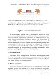
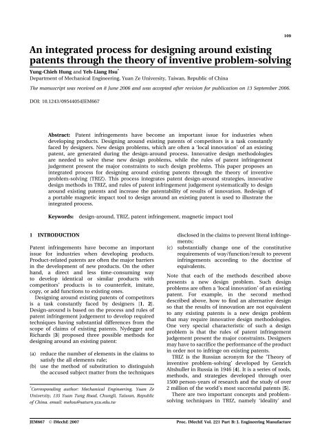
An integrated process for designing around existingpatents through the theory of inventive problem-solvingYung-Chieh Hung and Yeh-Liang Hsu *Department of Mechanical Engineering, Yuan Ze University, Taiwan, Republic of ChinaThe manuscript was received on 8 June 2006 and was accepted after revision for publication on 13 September 2006.DOI: 10.1243/09544054JEM667109Abstract: Patent infringements have become an important issue for industries whendeveloping products. Designing around existing patents of competitors is a task constantlyfaced by designers. New design problems, which are often a ‘local innovation’ of an existingpatent, are generated during the design-around process. Innovative design methodologiesare needed to solve these new design problems, while the rules of patent infringementjudgement present the major constraints to such design problems. This paper proposes anintegrated process for designing around existing patents through the theory of inventiveproblem-solving (TRIZ). This process integrates patent design-around strategies, innovativedesign methods in TRIZ, and rules of patent infringement judgement systematically to designaround existing patents and increase the patentability of results of innovation. Redesign ofa portable magnetic impact tool to design around an existing patent is used to illustrate theintegrated process.Keywords:design-around, TRIZ, patent infringement, magnetic impact tool1 INTRODUCTIONPatent infringements have become an importantissue for industries when developing products.Product-related patents are often the major barriersin the development of new products. On the otherhand, a direct and less time-consuming wayto develop identical or similar products withcompetitors’ products is to counterfeit, imitate,copy, or add functions to existing ones.Designing around existing patents of competitorsis a task constantly faced by designers [1, 2].Design-around is based on the process and rules ofpatent infringement judgement to develop requiredtechniques having substantial differences from thescope of claims of existing patents. Nydegger andRichards [3] proposed three possible methods fordesigning around an existing patent:(a) reduce the number of elements in the claims tosatisfy the all elements rule;(b) use the method of substitution to distinguishthe accused subject matter from the techniques* Corresponding author: Mechanical Engineering, Yuan ZeUniversity, 135 Yuan Tung Road, Chungli, Taiwan, Republicof China. email: mehsu@saturn.yzu.edu.twdisclosed in the claims to prevent literal infringements;(c) substantially change one of the constitutiverequirements of way/function/result to preventinfringements according to the doctrine ofequivalents.Note that each of the methods described abovepresents a new design problem. Such designproblems are often a ‘local innovation’ of an existingpatent. For example, in the second methoddescribed above, how to find an alternative designso that the results of innovation are not equivalentto any existing patents is a new design problemthat may require innovative design methodologies.One very special characteristic of such a designproblem is that the rules of patent infringementjudgement present the major constraints. Designersmay have to sacrifice the performance of the productin order not to infringe on existing patents.TRIZ is the Russian acronym for the ‘Theory ofinventive problem-solving’ developed by GenrichAltshuller in Russia in 1946 [4]. It is a series of tools,methods, and strategies developed through over1500 person-years of research and the study of over2 million of the world’s most successful patents [5].There are two important concepts and problemsolvingtechniques in TRIZ, namely ‘ideality’ andJEM667 Ó IMechE 2007 Proc. IMechE Vol. 221 Part B: J. Engineering Manufacture
110 Yung-Chieh Hung and Yeh-Liang Hsu‘contradiction solving’ [4]. The ideality of a system isthe measure of how close it is to the perfect system.The perfect system has all the expected benefits tothe customer with no cost and harmful effects. Theapplication of the concept of ideality can reducethe number of elements in the system to lowerproduct cost and enhance product benefits. Meanwhile,designing around the existing patents aimsto reduce the elements that constitute the claims orto replace the existing elements with different onessharing the same idea of ideality.However, when a design engineer tries to reducethe elements that constitute the claims or to replacethe existing elements with different ones, a systemincompatibility or conflict design problem is usuallycreated. That is, as the designer changes certainparameters of the system in a given design problem,this might adversely affect other parameters. In TRIZ,these are called ‘trade-off contradictions’. The‘trade-off’ means that the design engineer ‘trades’the improvement of one feature against deteriorationof another feature in the hope of finding a compromisesolution to the problem.In TRIZ, the concept of ‘contradiction solving’,which seeks to identify and eliminate contradictions,is almost the complete opposite of traditionalproblem-solving strategies, in which the emphasisis very firmly placed on the importance of achieving‘optimum’ compromises between the conflictingproblem parameters. If the conflicting componentsinvolve ‘inherent contradiction’ or ‘physical contradictions’,separation of action, space, or time isrecommended. If the contradictions are trade-offcontradictions, TRIZ introduces 40 principles witha contradiction matrix to solve about 1500 problemsinvolving technical contradictions.The present paper proposes an integrated processfor designing around existing patents through TRIZ.This process integrates patent design-around strategies,innovative design methods in TRIZ, and rules ofpatent infringement judgement systematically todesign around existing patents and increase thepatentability of results of innovation.Figure 1 shows the flow chart of this integratedprocess. To start with, the designer conducts standardpatent search and analysis to identify the relatedpatents to be designed around. The abstract list foreach concerned patent is developed to record thescope of claims and core techniques (or functions).Then, the independent claims of each concernedpatent are checked to see whether each element ofa concerned independent claim is necessary, tofind out the limitations of the claim terms of eachelement, and to examine if there are potentialdisadvantages or other characteristics existing inthe core techniques. In the mean time, the TRIZprocess is also initiated in this step. A ‘functionalmodel’ of each concerned patent is built to help thedesigner understand the relationship (useful function,harmful function, insufficient function, etc.)between elements of the core techniques.Next, the approaches of design-around areapplied. If one or more elements in the concernedpatent are found to be redundant in the previousstep, they can be eliminated directly to generatea solution with simplified components/functions.In the infringement analysis, the designing aroundis successful according to the ‘all elements rule’.If all elements are necessary, the designer has tomake at least one substantially different conditionon the way/function/result to prevent ‘doctrine ofequivalents’ infringement. This generates a newdesign problem. The new design problem is thensolved by the standard TRIZ process: to formulatethe design problem, to construct a new functionalmodel for the design model, to examine for contradiction,and to apply the inventive principle toobtain new solutions, or to perform so-called‘substance–field analysis’.The feasibilities of the new solutions are then evaluated.Finally, infringement analysis is performed tomake sure that the new design concepts do notinfringe on the original patent.An example of redesigning a portable magneticimpact tool is used to illustrate the integrationprocess of patent design-around. In the nextsections, two new design concepts of magneticimpact tool are generated to design around USPatent 6,918,449 using this process.The remainder of this paper is organized asfollows. Section 2 describes the impact tool designproblem and the process of ‘design-around’, andsections 3 and 4 describe two new design conceptsgenerated using the integrant process. Section 5describes infringement analysis of the two newdesign concepts. Finally, section 6 concludes thepaper.2 DESIGNING AROUND US PATENT 6,918,449Portable power tools used for drilling and fasteningare expected to be relatively small and light, yetprovide high power to perform the desired functions.Figure 2 shows the major components of a portablepower tool driven by an electric motor. The rotationalmotion of the motor is transmitted to thechuck holding the tool output shaft by means ofa hammer. The motor is generally small owing torestrictions imposed on the overall size and weightof the portable power tools. The limited power ofthe small motor might not be enough to drive theintended load. A hammer-type mechanism is usedto generate high output torque from a small drive.Proc. IMechE Vol. 221 Part B: J. Engineering Manufacture JEM667 Ó IMechE 2007
An integrated process for designing around existing patents through TRIZ 111Fig. 1Flow chart for integrating design-around with TRIZmotorFig. 2chuckhammer tool bitchuckComponents of a portable power toolAs shown in Fig. 3, the hammer stores the rotationalenergy of the motor over a large angle ofrotation, for example, a half-turn. The hammerthen hits the chuck to create an impact torque overa small angle of rotation of the chuck (for example,10 ). In this type of portable power tool, loud noiseis generated when the hammer hits the chuck.JEM667 Ó IMechE 2007 Proc. IMechE Vol. 221 Part B: J. Engineering Manufacture
112 Yung-Chieh Hung and Yeh-Liang HsuFig. 3chuckhammermotorhammerchuckTop plan view of a hammer-type impact generatorTo eliminate the hammering noise, some patentshave proposed the concept of a magnetic impacttool with which screws are tightened using magneticcoupling to deliver a strike without any contact.A tightening rotational impact force is obtainedwithout a collision sound. The successful exampleof a magnetic impact tool is disclosed in US Patent6,918,449 [6]. As shown in Fig. 4, the magneticimpact tool comprises a magnetic hammer drivenby a motor, a magnetic anvil disposed so as to facethe magnetic hammer, and an output shaft thatrotates together with the magnetic anvil. Themagnetic hammer is movable with respect to themagnetic anvil without contact.A rotational impact force is magnetically generatedin a non-contact manner for the magneticanvil in conjunction with the rotation of themagnetic hammer. During the screw tighteningwork, for example, when the load torque is initiallylow, the magnetic hammer and magnetic anvil beginto rotate together without any impact action. Whenthe load torque exceeds the magnetic attractiontorque, the magnetic hammer and magnetic anvilare no longer synchronized. Impact action can begenerated, and screw tightening and looseningwork can be carried out even if a low-torque motoris used.The torque generated between the magnetichammer and magnetic anvil can be changed by thechanging device to vary the distribution ratio ofthe magnetic flux from the magnetic hammer tothe magnetic anvil. As shown in Fig. 4, there isa magnetic bypass device for distributing magneticflux between the magnetic anvil and the magnetichammer. There is also a changing device for changingthe distribution of magnetic flux. The changingdevice comprises a micromotor (25a), a worm gear(25b), and a pinion gear (25d). The pinion gear ismounted on the external peripheral surface of thebypass device (24a). The bypass device can bemoved in a reciprocating manner in the axialdirection of the driveshaft by driving the micromotor.Thus, the distribution of magnetic fluxbetween the magnetic hammer and magnetic anvilcan be changed. A switch for controlling the operationof the micromotor may be provided separately.A standard design-around approach is first appliedto US Patent 6,918,449. Nydegger and Richards [3]summarized the process of designing aroundpatents as follows.Step 1. To search related patents.Step 2. To develop the abstract list for each concernedpatent.Step 3. To check whether each element of a claim of theselected patent in the second step is necessary or not.Step 4. To inspect whether limitations of terms existin the elements.Step 5. To examine if there are potential disadvantagesor other characteristics existing in the coretechniques owing to the generation of some functionor specific effects in the patented invention.Step 6. To try to use various approaches of implementationto have substantially different functions.Step 7. To compare the results from design-aroundand the objective patent.In this research, US Patent 6,918,449 is the target fordesign-around (step 1). There are seven technologicalcharacteristics in the independent claim ofthis patent (step 2):(a) a motor for generating rotational force;(b) a driveshaft rotatably driven by the motor;(c) a magnetic hammer rotatably moved in acoupled state with the driveshaft;(d) a magnetic anvil that faces the magnetichammer and to which the rotational force istransmitted by magnetic coupling, with one ofthe opposing surfaces of the magnetic hammerand magnetic anvil having a magnetic pole,and the other having a magnetic pole ormagnetic body;(e)(f)(g)an output shaft rotated by the magnetic anvil;a magnetic bypass device that bypasses themagnetic flux between the magnetic anvil andthe magnetic hammer, and changes the stateof magnetic coupling there between;a changing device that changes the bypassquantity of the magnetic flux with the magneticbypass device, with the torque transmitted fromthe magnetic hammer to the magnetic anvilbeing changed in accordance with the changein bypass quantity of the magnetic flux variedby the changing device.For steps 3 to 5, the technology/function matrix of USPatent 6,918,449 is constructed as in Table 1, in orderto investigate the techniques that can produce thespecific functions. For example, in the third columnProc. IMechE Vol. 221 Part B: J. Engineering Manufacture JEM667 Ó IMechE 2007
An integrated process for designing around existing patents through TRIZ 113Fig. 4 US Patent 6,918,449TechnologiesTable 1Technology/function matrixTighten/loosenscrewMotor Magnetic hammerMagnetic anvil Driveshaft Output shaft Magneticbypass deviceChanging deviceFunctionsGenerateimpact torqueChangemagnetic fluxSteps 1 to 5 of the process of designing aroundpatents are more operational types of task. Notethat these five steps are already reflected in theupper half of the flow chart for integrating designaroundwith TRIZ in Fig. 1. The actual implementationin step 6 involves engineering design work.In the following sections, two new design conceptsof the magnetic impact tool are generated to designaround US Patent 6,918,449 using the integratedprocess for designing around existing patentsthrough TRIZ, following the bottom half of the flowchart in Fig. 1 with two different approaches.in Table 1, the assembly of magnetic bypass deviceand changing device makes the magnetic flux vary.In Table 1, ‘tighten/loosen screw’ and ‘generateimpact torque’ are two fundamental functions forthe magnetic impact tool, and the five related components(the motor, the driveshaft, the output shaft,the magnetic hammer, and the magnetic anvil) arehard to reduce or replace. Therefore, the magneticbypass device and the changing device are selectedas the target for design-around.3 GENERATING A NEW CONCEPT OF THEPORTABLE MAGNETIC IMPACT TOOL3.1 Check the independent claim of US Patent6,918,449The scope of claim and core techniques of US Patent6,918,449 has been described in section 2 (step 2). Inthis step, constructing a functional model can furtherhelp the designer to understand the relationshipJEM667 Ó IMechE 2007 Proc. IMechE Vol. 221 Part B: J. Engineering Manufacture
114 Yung-Chieh Hung and Yeh-Liang HsuFig. 5 Functional model for US Patent 6,918,449between the elements of the core techniques.Figure 5 shows the functional model of US Patent69,18,449. A rectangle in Fig. 5 represents a ‘systemcomponent’, which is the basic element constitutinga system or a product. A hexagon represents a ‘supersystem’, which is an essential factor that will influencecomponents of the system. An ellipse representsa ‘target’, which is the acceptor of the majorfunction in the engineering system. A solid linerepresents relational actions linking the variouscomponents.In the original design, the motor, the driveshaft,the output shaft, the magnetic hammer, and themagnetic anvil are the five important system componentsfor generating impact torque, which is themajor function (or primary useful function) of themagnetic impact tool. The output shaft is also necessaryto tighten or loosen screws. The other twocomponents, the magnetic bypass device and thechanging device, are the auxiliary elements toprovide the function of adjusting the value of impacttorque.3.2 Apply the approaches of design-aroundReferring to Fig. 1, there are two possible designaroundapproaches. In this section, the approach of‘eliminating one or more elements of a claimedsystem’ is used.As discussed earlier, the application of the conceptof ‘ideality’ in TRIZ can reduce the number ofelements in the system to lower product cost andenhance product benefits. Commercial softwareTechOptimizer 4.0 from Invention Machine Corporation[7] was used to ‘trim’ the original functionmodel and generate a new design concept to achievethe goal of ideality.Trimming is a method for improving systemsbased upon the elimination of components that areproblematic, costly, or unessential in the system. Inthis research, after value analysis on the functionalmodel for US Patent 6,918,449, the changing devicewas chosen to be eliminated. Without the changingdevice, the bypass device cannot work by itself andshould also be eliminated. The simplified functionalmodel is shown in Fig. 6. The dotted squares anddotted lines are the components and the relationalactions to be trimmed respectively. In addition,some relational actions from the original designmay be eliminated or transferred as a result of reconfiguringthe system.3.3 Formulate the new design problemWithout the changing device and the bypass device,the impact torque cannot be adjusted and the wholefunction of the magnetic impact tool deteriorates.Therefore, the useful functions of the eliminatedcomponents have to be redistributed. As shown inFig. 6, the function ‘change magnetic flux’ originallyprovided by the changing device and the bypassdevice will be provided by the magnetic anvil. TwoProc. IMechE Vol. 221 Part B: J. Engineering Manufacture JEM667 Ó IMechE 2007
An integrated process for designing around existing patents through TRIZ 115Fig. 6 Simplified functional model for US Patent 6,918,449Featureto changeTable 2Contradiction matrixUndesired result1 ... 33 ... 39Weight of ... Ease of ... Productivitymoving object operation1 Weight ofmoving object... ...10 Force 1, 28, 3, 25... ...39 Productivitynew design problems occur during the trimmingprocess:(a) how to add the function of ‘changing magnetflux’ in the magnetic anvil;(b) how to ‘adjust the magnet flux’ by the magneticanvil.Note that the two new design problems are not independentand have to be solved simultaneously.3.4 Examine for contradictions and apply theinventive principlesIn this section, the contradiction matrix (Table 2)and the inventive principles from TRIZ are used tosolve these two new design problems. In TRIZ, forceis defined as any interaction that is intended to changethe condition of an object. Therefore, parameter 10(force) is selected as the feature to change for addingthe function of ‘changing magnet flux’ in themagnetic anvil, as shown in Table 2. In the meantime, it is still hoped to be able to ‘adjust the magnetflux’ by the magnetic anvil. Therefore, parameter 33(ease of operation) is selected as the feature not tobe adversely affected in Table 2. In TRIZ, ease ofoperation means that convenience and facility withwhich an object or system is operated.As shown in Table 2, four inventive principles canbe obtained. They are principle 1 (segmentation),principle 28 (mechanical interaction substitution),principle 3 (local quality), and principle 25 (selfservice).After reviewing the four principles, principle 28was utilized to generate the new concept in theportable magnetic impact tool. In TRIZ, principle28 has four explanations:(a) replace a mechanical system with an optical,acoustic, thermal, or olfactory system;(b) use an electric, magnetic, or electromagneticfield to interact with an object;(c) replace fields that are: stationary with mobile,fixed with changing in time, random with structured;(d) use fields in conjunction with ferromagneticparticles.In particular, it was decided to apply ‘use an electric,magnetic, or electromagnetic field to interact withan object’ to solve the new design problems.JEM667 Ó IMechE 2007 Proc. IMechE Vol. 221 Part B: J. Engineering Manufacture
116 Yung-Chieh Hung and Yeh-Liang HsuFig. 7(a) Original design and (b) simplified design of the magnetic flux adjustment device3.5 New concept of the portable magneticimpact toolIn the original design of US Patent 6,918,449, theadjustment device of magnet flux consists of thechanging device and the bypass device, as shown inFig. 7(a). The changing device comprises a micromotor,a worm gear, and a pinion gear. The piniongear is mounted on the external peripheral surfaceof the bypass device. The bypass device can bemoved in a reciprocating manner in the axial directionof the driveshaft by driving the micromotor.Thus, the distribution of magnetic flux between themagnetic hammer and the magnetic anvil can bechanged.Figure 7(b) shows the derivation of the solutionusing principle 28 in TRIZ. Electromagnets are usedin the magnetic anvil, and the impact torque canbe changed by varying the distribution ratio of themagnetic flux by operating a switch for setting theoutput of the electric current value. In this concept,the electromagnet anvil has already replaced thefunction of the changing device and the bypassdevice.Figures 8 and 9 illustrate this new design conceptin more detail. The basic structure of the magneticimpact tool remains unchanged. The motor assemblycomprises a motor and a reduction gear, withan output shaft protruding from the reduction gear.As shown in Fig. 9, the magnetic hammer comprisesfour magnets, and the magnetic hammer rotateswith the driveshaft.The magnetic anvil comprises an axle unit that hasa bit hole for attaching a tool bit (not depicted) to thetip, and four L-shaped magnetic anvil arms. Themagnetic anvil arms are positioned at equal intervalsalong the circumference and are orthogonal to theaxle unit. The magnetic anvil has four solenoids asshown in Fig. 9. When the voltage is applied to thesolenoids, it generates a current in the solenoidsthat in turn produces a magnetic field. Therefore,by changing the electric current, the intensity of themagnetic field changes correspondingly.In order to provide electric current to the solenoids,there are two electroconvulsive metal ringspositioned in front of the output shaft of themagnetic anvil, as shown in Fig. 8. One of the electroconvulsivemetal rings has a positive electrodeand the other has a negative electrode. Rotationalforce is magnetically generated in a non-contactmanner by the magnetic anvil in conjunction withProc. IMechE Vol. 221 Part B: J. Engineering Manufacture JEM667 Ó IMechE 2007
An integrated process for designing around existing patents through TRIZ 117Fig. 8 New concept of the portable magnetic impact tool (1)Fig. 9 New concept of the portable magnetic impact tool (2)the rotation of the magnetic hammer. The torquegenerated between the magnetic hammer and themagnetic anvil can be changed by varying the distributionratio of the magnetic flux by operatinga switch for setting the output of the electriccurrent value of the four solenoids.4 ALTERNATIVE DESIGN CONCEPT OF THEPORTABLE MAGNETIC IMPACT TOOLIn section 3, the contradiction table and the inventiveprinciples from TRIZ are used to generatea new design concept in which the changing deviceand the bypass device are eliminated and their functionsare built into the magnetic anvil. Referring toFig. 1, the other design-around approach is ‘tomake way/function/result substantially different’.In this section, the substance–field analysis fromTRIZ is used to generate an alternative designconcept in which the way to generate and adjustimpact torque is substantially different from theoriginal patent.4.1 Apply the approaches of design-aroundIn the original design of US Patent 6,918,449, themagnetic anvil rotates together with the magneticJEM667 Ó IMechE 2007 Proc. IMechE Vol. 221 Part B: J. Engineering Manufacture
118 Yung-Chieh Hung and Yeh-Liang HsuFig. 10 Functional model of the alternative design of US Patent 6,918,449hammer. In order to make way/function/resultsubstantially different from the original design, weattempted to generate an alternative design conceptthat changes the method of generating rotationalimpact force. Analogous to the mechanical impacttool as shown in Fig. 3, in which the chuck is stationarywhile the hammer is rotated by the motor, themagnetic anvil is kept stationary in the new designconcept.Figure 10 shows the functional model of this alternativedesign concept. Now the magnetic anvil doesnot rotate with the magnetic hammer. The function‘impact torque’ is magnetically generated in a noncontactmanner by the rotational magnetic hammerand the fixed magnetic anvil. The other function‘change magnetic flux’ originally provided by thechanging device and bypass device will be providedby the magnetic anvil, and the two components areeliminated.4.2 Formulate the new design problemAgain, two new design problems occur during thedesign-around process:(a) how to generate the function ‘impact torque’between the fixed magnetic anvil and the rotationalmagnetic hammer;(b) how to add the function ‘changing magnet flux’to the fixed magnetic anvil.Fig. 11Smallest block triangle of a Su–Field modelIn the previous section, the contradiction matrix andthe inventive principles in TRIZ were used to solvethe design problems occurring in the design-aroundprocess. Here, the substance–field analysis fromTRIZ was deliberately chosen to solve these twodesign problems.4.3 Substance–field analysis and application ofthe 76 standard solutionsSubstance–field analysis (Su–Field analysis) is a TRIZanalytical tool for modelling problems related toexisting technological systems. Designers constructSu–Field models to clear the contradictions in theirdesign problems. The function model must containmore than two substances and their interactions.Figure 11 shows the smallest block triangle ofa Su–Field model. The identification of substancesdepends upon the application. Either substancecould be a material, tool, part, person, or environment.In Fig. 11, substance 1 is the recipient of theProc. IMechE Vol. 221 Part B: J. Engineering Manufacture JEM667 Ó IMechE 2007
120 Yung-Chieh Hung and Yeh-Liang HsuFig. 14Operation of the new design conceptfour magnets and eight pole plates that sandwich thepoles. The magnetic hammer is driven by the motorand has an axle unit that has a bit hole for attachingthe tool bit to the tip.The electromagnetic anvil comprises two solenoids,which are positioned at 180 relative to eachother. When a voltage is applied to the solenoids, itproduces a magnetic field. The force of the solenoidmagnetic field attracts the magnetic hammer. Bychanging the voltage, the intensity of the magneticfield can be changed.The function of impact torque in this new designconcept is explained in Figs 14(a) to (c). In thesefigures, only a hammer and an anvil are illustratedto simplify the explanation. Referring to Fig. 14(a),a small clockwise rotation of the hammer (for example,5 ) results in the hammer being attracted magneticallytowards the forward anvil. Under thetorque of magnetic attraction, voltage is applied tothe solenoid and the hammer accelerates towardsthe forward anvil. In Fig. 14(b), the shifting angleformed between the hammer and the anvil is equalto zero. At this angle, magnetic field lines emanatingfrom the anvil travel through the ferromagneticmaterial of the corresponding hammer to completethe magnetic circuit. Accordingly, the hammer is ata stable equilibrium, being attracted strongly to theanvil. Note that the voltage is still applied to the solenoidduring their action. Referring to Fig. 14(c), if thehammer rotates slightly in a clockwise direction (forexample, 5 ), the hammer feels a pull towards theanvil as a result of magnetic attraction. If the electriccurrent in the solenoid is briefly cut off, the magneticattraction torque is reduced, establishing themagnetic impact condition.5 INFRINGEMENT ANALYSISTwo new design concepts (concept A described insection 3 and concept B described in section 4) ofthe portable magnetic impact tool have been generated.Referring to Fig. 1, when a new solution is generated,the last step is to carry out an infringementanalysis to make sure the new solution does notinfringe on the original patent.In general, the judgement of infringement in patentlawsuits consists of three steps. They are the judgementsby ‘all elements rule’, ‘doctrine of equivalents’,and ‘doctrine of file wrapper estoppel’. The first twojudgements are normally used to establish whetheror not the new design concepts infringe on the originalpatents. First, if the elements of claims can beread on the components that appear in the accusedsubject matter, the all elements rule is satisfied witha literal infringement. In other words, if the accusedsubject matter contains all of the elements that constitutethe claim, infringement may occur. Second, ifthe all elements rule is not satisfied, but the elementsin the accused subject matter corresponding tothose in the claims substantially use the sameway, substantially perform the same function, andsubstantially obtain the same result (also namedtriple identity test, way/function/result testing), thetechniques under investigation are considered to beequivalent to those in the claims.Proc. IMechE Vol. 221 Part B: J. Engineering Manufacture JEM667 Ó IMechE 2007
122 Yung-Chieh Hung and Yeh-Liang Hsugenerated between the magnetic hammer andelectromagnetic anvil can be changed by varyingthe distribution ratio of the magnetic flux by settingthe voltage from the electromagnetic anvil. A highvoltage increases the magnetic force of the electromagneticanvil, and vice versa.The original patent and new design concept B arealso substantially different in both ‘generation ofimpact torque’ and ‘change of magnetic flux’. First,the magnetic hammer rotates in sync with the motorbut the electromagnetic anvil is fixed. Second, thetorque generated between the electromagnetic anviland the magnetic hammer can be changed byvarying the distribution ratio of the magnetic fluxby setting the voltage from the electromagneticanvil. Third, the magnetic impact condition iscontrolled by the supply of electric current.As discussed above, results of innovation arepatentable and do not infringe upon the existingpatent. In these two new design concepts, thenumber of system components is reduced but alldesign requirements can still be met. Further productdevelopment can be carried out; issues in commercializationsuch as reducing the manufacturingcost of each component should also be considered.6 CONCLUSIONSystematic product design processes commonlyseen in research literature or design textbooks oftenstart from need-finding, specification development,conceptual design, detail design, to production.However, the design problems constantly faced byengineering designers in industries is how to designaround existing patents, which requires a completelydifferent design approach and knowledge.This paper proposes an integrated process fordesigning around existing patents through TRIZ.This process integrates patent design-around strategies,innovative design methods in TRIZ, and rules ofpatent infringement judgement. Facing innovationbarriers and possible patent disputes, the designproblem to be solved is first identified using thedesign-around strategies, as well as the functionmodel and value analysis in TRIZ. This ‘localinnovation’ design problem is then solved by TRIZmethodology, which not only avoids a trial and errordesign approach but also increases the degree ofinnovation. Finally, the feasible solutions generatedby TRIZ are analysed using the ‘triple identity test’(way/function/result testing) to make sure that thenew design concepts do not infringe on the originalpatent.In this design-around process, the rules of patentinfringement judgement present the major constraintsto local innovation design problems.Designers may have to sacrifice the performance ofthe product in order not to infringe on existingpatents, and the performance of the new designmay not exceed that of the original patent. However,this process provides a systematic way to generate anew design that is patentable and less likely toinfringe upon the existing patent. This integratedprocess should be especially helpful to technologyfollowers in developing their products speedily andwith a lower cost.ACKNOWLEDGEMENTThis project is partially supported by the Fuel CellResearch Centre, Yuan Ze University. This supportis gratefully acknowledged.REFERENCES1 Glazier, S. C. Patent strategies for business, 1990 (Lawand Business Institute).2 Miele, A. L. Patent strategy: the Manager’s guide toprofiting from patent portfolios, 2000 (John Wiley &Sons, Inc., New York).3 Nydegger, R. and Richards, J. W. Design-around techniques.In Electronic and software patents (Eds S. W.Lundberg et al.), 2000 (The Bureau of National Affairs,Inc., Washington, DC).4 Terninko, J., Zusman, A., and Zlotin, B. Systematicinnovation: an introduction to TRIZ, 1998 (St LuciePress, Boca Raton, Florida).5 Mann, D. Hands-on systematic innovation, 2002(CREAX Press, Belgium).6 Shinagawa, S., Nakayama, S., and Sekino, F. Magneticimpact tool. US Pat. 6,918,449, 2005.7 Invention Machine Corporation, http://www.inventionmachine.com/Proc. IMechE Vol. 221 Part B: J. Engineering Manufacture JEM667 Ó IMechE 2007