
Create successful ePaper yourself
Turn your PDF publications into a flip-book with our unique Google optimized e-Paper software.
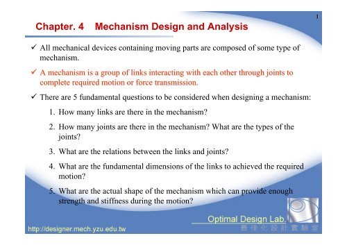
<strong>Chapter</strong>. 4 <strong>Mechanism</strong> <strong>Design</strong> <strong>and</strong> <strong>Analysis</strong>1 All mechanical devices containing moving parts are composed of some type ofmechanism. A mechanism is a group of links interacting with each other through joints tocomplete required motion or force transmission. There are 5 fundamental questions to be considered when designing a mechanism:1. How many links are there in the mechanism?2. How many joints are there in the mechanism? What are the types of thejoints?3. What are the relations between the links <strong>and</strong> joints?4. What are the fundamental dimensions of the links to achieved the requiredmotion?5. What are the actual shape of the mechanism which can provide enoughstrength <strong>and</strong> stiffness during the motion?
Links2 Conceptually a link is considered as a rigid body that will not deform under theloads during the motion. A link is not necessarily a “stick-like part”. A link may be composed of severalparts assemble together, <strong>and</strong> move as a rigid body during motion. How many links are there in a bicycle?
Planar <strong>Mechanism</strong>3 The planar mechanism is the most common type of mechanism. The trajectoryof one point on the planar mechanism lies on a plane during motion. Thetrajectory of all points on the planar mechanism lie on planes which are parallelto each other. For example, a door is a simple planar mechanism that consists of a moving link<strong>and</strong> a ground link. This mechanism can be described on a plane. In a spatial mechanism, the motion of the links is not planar. For example, thetrajectories of the links in a spherical mechanism form concentric spheres.
Joints in a Planar <strong>Mechanism</strong>4 Links are connected by joints. There are 3 types of joints:• Revolute joint permits rotational motion with respect to a fixed axis.• Prismatic joint permits translational motion between of a pair of links.• Direct contact joint permits both rotation <strong>and</strong> slide between links.θ Both revolute joint <strong>and</strong> prismatic joint are single-DOF joints. Only one parameteris needed to describe the relative position between two links. The direct contactjoint is a 2-DOF joint.
Linkage <strong>Design</strong> (I)6 The function of a mechanism in a machine is to convert the input force ormotion into desired output. In a linearly proportional mechanism, the output motion or force is linearlyproportional to the input. In some mechanisms, the relation between output <strong>and</strong> input is nonlinear. Thenumber, type <strong>and</strong> connectivity of joints, <strong>and</strong> the length of links determine thecharacteristic of the mechanism. Such mechanism is called a linkage. The purpose of linkage design is to decide the length of the links, the position<strong>and</strong> type of the joints, <strong>and</strong> how to assemble the links so that the e desired motioncan be achieved.
Linkage <strong>Design</strong> (II)7 When analyzing a linkage, we often use a “skeleton diagram” to represent thetype of joints, distances between joints, <strong>and</strong> which joints connect which links inthe linkage
Linkage <strong>Design</strong> (III)82 bars3 bars4 bars The close-loop four-bar linkage has only 1 DOF, i.e., . only one actuator is neededto drive the linkage. It is the most popular <strong>and</strong> well-studied linkage.
Four-Bar Linkage Four-Bar Linkages can be used for non linear motion transmission.9 In a four-bar linkage, Grashof’s Law determines whether there is a link that canrotates 360 degree.• If the sum of length of the longest <strong>and</strong> shortest links are less than the sum oflength of the other two links, there must be a link that can rotate 360 degree.• If not, no link can rotate 360 degree. When Grashof’s Law is satisfied, there are 3 possible mechanisms: crank <strong>and</strong>rocker, double crank, <strong>and</strong> double rocker.
Crank <strong>and</strong> Rocker <strong>Mechanism</strong>10 The shortest link is input crank or output crank. Input crank or output crankrotates 360 degrees.
Double Crank <strong>Mechanism</strong>11 The shortest link is ground link. Both input crank <strong>and</strong> output crank rotate 360degrees.
Double Rocker <strong>Mechanism</strong>12 The shortest link is coupler link. The coupler link can rotate 360 degrees.
Example 1. Windshield Wiper <strong>Mechanism</strong>13 The windshield wiper mechanism can bedivided into two 4-bar linkages: (1, 2, 3, 4)<strong>and</strong> (1, 4, 5, 6). Linkage (1, 2, 3, 4) is a crank <strong>and</strong> rockermechanism. Link 2 is the input crankwhich rotates 360 degree to drive otherlinks. Linkage (1, 4, 5, 6) is a double rockermechanism. Link 4 is the input crank,which drives link 6 to rotate with the samedirection <strong>and</strong> angular speed. Linkage (1, 4, 5, 6) is called “parallelmechanism”.motorwiper
Other Linkages14 Slider crank (crank <strong>and</strong> slider) mechanism has 4 links, 3 revolute joints <strong>and</strong> 1prismatic joint. As in the reciprocating engine, this mechanism convertsreciprocating motion (piston) into rotational motion (crank). Double slider mechanism has 4 links, 2 revolute joints <strong>and</strong> 2 prismatic joints.
Practice 3. <strong>Mechanism</strong> of Casement Window151. How many links <strong>and</strong> joints are there in this mechanism? Which are the input links?Which are the output links? What are their types?2. Measure the distance between each joint. Draw a skeleton diagram. Be careful with thescale of the links.3. Make a model of this mechanism using pasteboard <strong>and</strong> other suitable materials.4. Operate your model <strong>and</strong> find out the maximum opening angle of the windows. Can youcalculate the result?5. If you want a larger opening angle, how do you modify the length of links? Make amodel again to verify the result. Is there any limit of the angle?
Calculating Degrees of Freedom of a Linkage16 A movable link in a planar mechanism has 2 translational DOF <strong>and</strong> 1 rotationalDOF. A revolute joint constrains 2 translational DOF. A prismatic joint constrains 1translational DOF <strong>and</strong> 1 rotational DOF. For the casement window mechanism, the number of total degree of freedom is:6 revolute joints, 1 prismatic joint3×(6-1)-2×(6+1)=16 links, 1 ground link For the windshield wiper mechanism, the number of total degree of freedom is:7 revolute joints3×(6-1)-2×7=16 links, 1 ground link
Example 2. <strong>Analysis</strong> of Slider Crank <strong>Mechanism</strong>17 Many computer simulation software can be used for mechanism analysis. After the length of the links, the number, type, <strong>and</strong> connectivity of the joints aredecided, force analysis <strong>and</strong> stress analysis are needed to design the actual size <strong>and</strong>shape of the links. A reciprocating force (0N-5N) is exerted on the slider in –x direction. The periodis 0.898 sec.
Example 2. <strong>Analysis</strong> of Slider Crank <strong>Mechanism</strong>18 The analysis results show that, the maximum angular velocity of link 1(2059.98deg/s) <strong>and</strong> the maximum constraint force (42.72N)of joint 2 occur atthe same time t=0.535 sec.