Autop 2-Post - Mohawk Lifts
Autop 2-Post - Mohawk Lifts
Autop 2-Post - Mohawk Lifts

Create successful ePaper yourself
Turn your PDF publications into a flip-book with our unique Google optimized e-Paper software.
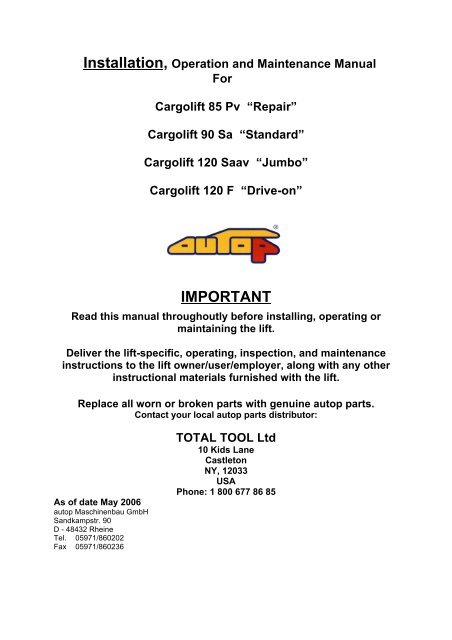
Installation, Operation and Maintenance ManualForCargolift 85 Pv “Repair”Cargolift 90 Sa “Standard”Cargolift 120 Saav “Jumbo”Cargolift 120 F “Drive-on”IMPORTANTRead this manual throughoutly before installing, operating ormaintaining the lift.Deliver the lift-specific, operating, inspection, and maintenanceinstructions to the lift owner/user/employer, along with any otherinstructional materials furnished with the lift.Replace all worn or broken parts with genuine autop parts.Contact your local autop parts distributor:As of date May 2006autop Maschinenbau GmbHSandkampstr. 90D - 48432 RheineTel. 05971/860202Fax 05971/860236TOTAL TOOL Ltd10 Kids LaneCastletonNY, 12033USAPhone: 1 800 677 86 85
autop CargoliftInstallation instructionWarning:DO NOT permit personnel to operate lifts who are not familiar with the informationcontained in these instructions.Safety devices and controls are provided for your protection. DO NOT alter anydevices to serve a special purpose. Never interfere with safety features built into thecontrols or the lift lock.NOTICE:This automotive lift complies with all requirements of the current American NationalStandard ANSI / ALI ALCTV – 1998, as issued by the Automotive Lift Institute, andapproved by the American National Standard Institute. This standard referencesANSI / ALI ALOIM – 1994 Safety Requirements For Operation, Inspection, AndMaintenance that describes the Owners / Employer responsibilitiesStudy these Instructions carefully to become familiar with the general installationprocedure. Before installing your autop lift, inspect the lift to insure that it is completeand undamaged. If it is apparent that the lift has been mishandled in shipment, or ifparts are missing, not the damage or missing parts on the shipping papers and notifyTOTAL TOOL LTD immediately. Phone: 1 800 677 86 859000069.doc1
autop CargoliftInstallation instructionContents1.0 Important Safety Instructions 32.0 Overview of the structural components 42.1 Component packing list 53.0 Setting, aligning and concrete mounting of the steel cassette 64.0, 4.1 and 4.4 only for repairs and modifications of the lift4.0 Installation of the lifting unit 84.1 Installation of the cylinder 84.2 Installation and connection of the pump- and control unit and 10the load holding device.4.3 Adjustment of the cylinder 134.4 Installation of the load holding device 135.0 Connection drawings (electric, hydraulic, pneumatic) 14Pneumatic diagramm 15Hydraulic diagramm 166.0 Installation of the superstructure 177.0 Installation of the cassette cover 178.0 Instruction of personnel in operating the lift 189.0 Final checkout 182
autop CargoliftInstallation instruction1.0 Important Safety InstructionsWhen using your garage equipment, basic safety precautions should always befollowed, including the following:1. Read all instructions.2. Care must be taken as burns can occur from touching hot parts.3. Do not operate equipment with a damaged cord. If the equipment has beendropped or damaged do not operate until it has been examined by a serviceman.4 .Do not let cord or hoses come in contact with hot manifolds or moving fan blades.5. If an extension cord is necessary, a cord with a current rating equal to or morethan that of the equipment should be used. Cords rated for less current than theequipment may overheat. Care should be taken to arrange the cord so that it willnot be tripped over or pulled.6. Always unplug equipment from electrical outlet when not in use. Never use thecord to pull the plug from the outlet. Grasp plug and pull to disconnect.7. To reduce the risk of fire, do not operate equipment in the vicinity of opencontainers of flammable liquids (gasoline). WARNING: Risk of Explosion: Thisequipment has internal arcing and sparking parts, which should not be exposed toflammable vapors. This equipment is only suitable for installation in a garagehaving sufficient air circulation to be considered a non-hazardous location.8. Adequate ventilation should be provided when working on operating internalcombustion engines.9. Keep hair, loose clothing, fingers, and all parts of body away from moving parts.10. To reduce the risk of electrical shock, do not use on wet surfaces or expose torain.11. Use only as described in this manual. Use only manufacturerʼs recommendedattachments.12. ALWAYS WEAR SAVETY GLASSES. Everyday eyeglasses only have impactresistant lenses, they are NOT safety glasses.SAVE THESE INSTRUCTIONSRev (8/3/98)3
autop CargoliftInstallation instruction2.0 Overview of the structural componentsThe Cargolift series components are shown schematically in fig. 1.1Fig. 1.1 Overview of the structural components4
autop CargoliftInstallation instruction2.1 Component packing list1. One Steel cassette, coated with rust protective paint including a woodenaluminumcover.2. Hydraulic unit including two cylinders a synchronizing bar and two guides.Pre-fitted in the cassette3. SPX – pump unit including air pressure switch for load holding device.4. Load holding device including synchronizing sleeve and lock ladder.Pre-fitted in the cassette5. Hydraulic- and pneumatic distributors with hydraulic- and air pressure hoses.6. One set of superstructure 85 Pv, 90 Sa, 120 Saav or F 480.7. Package of screws and bolts.8. Installation, operation and maintenance manual.9. Placard with safety warning labels for inground lifts ALI/WL50010. Vehicle lifting points for frame engaging lifts ANSI/SAE J2184 05/2000Documents mentioned in 8, 9, and 10 must delivered to the owner or employerThe purchaser or installer of the lift must furnish following items:1. Wiring devices for electrical power supply, 230 VAC, 1 phase, 60 Hz,25 A (time-delay fuses)2. compressed air supply 8 – 10 bar (115 – 145 psi) to the power unit and to thecassette for the load holding device and the air connector at the superstructure.3. An air regulator filter must be installed for the compressed air supply.5
autop CargoliftInstallation instruction3.0 Setting, aligning and Before installation check the location of theconcrete mounting lift. Allow plenty of working room on all sidesof the steel cassette as well as room for workbenches, aisles,lubrication equipment and other obstructions.The overhead clearance should be at least12 feet.In existing buildings a trench of approx. 7’ x3’3” must be broken out.Refer to the recommended measurements onthe foundation drawing F 413184b.Lower the steel cassette with a suitable lifting unit(chain hoist, forklift, crane,….) into the foundationand fix the cassette with two mounting rails, whichshould be screwed on the cassette and fastenedto the floor with dowels, or put weight on thecassette so that it can not “float”.6
autop CargoliftInstallation instructionlevelspacer blockTop of finished floor levelhas to be marked by thearchitect.steel cassetteFig. 2.1 Installation of the steel cassetteThe cassette must be perfectly adjusted in lengthand width to the level of the finished floor +1/8”.To prevent water in the lift the steel cassette hasto be mounted in concrete at 1/8“ above finishedfloor. Slope concrete away from the frame.Pour concrete in two or three separate steps eacha few hours time distance apart to allow theconcrete to lightly set between pours.DO NOT use the lift until the concrete has fullycured to 3500 psi.In case of a high ground water table watertightconcrete has to be used.7
autop CargoliftInstallation instructionOnly for repairs and modifications of the lift4.0 Installation of the Before installation of the lifting unit the transportlifting unit sealings and the cross struts inside of the cassetteneed to be removed.Only for repairs and modifications of the lift4.1 Installation of the If necessary the synchronizing bars should becylindermounted onto the cylinder. For this proceed asfollows:- Turn the cylinder in so that the hose connectionis on top.- Unscrew the straight union- Use a suitable anti corrosion spray (partno.08005) on the synchronizing rod’s hoop.- Slide the synchronizing bar opening over thecylinder and fasten it with the DIN 933 M 16x40-9.8-vz screws. The tightening torque should be210 Nm.- Afterwards screw the straight union back into thecylinder.Install the prepared cylinder into the cassette asfollows:- Put the flat seal onto the foundation frame.- Screw two M20 eye bolt diagonally into thesupporting guide and lower the cylinder into thecassette by using a suitable lifting unit.When setting the cylinders make sure that thehydraulic connection of the cylinder is on thesame side as the distributor in the cassette.- Unscrew the two eyebolt and put the ten M16x 40-8.8 vz – DIN 6912 screws in and tighten these.- Install the second cylinder analogue to the firstone.8
autop CargoliftInstallation instruction----- After installing both cylinders the transport safetyscrews on the piston must be replaced withbleeding screws M 10x16–DIN 912 (part no.30108) including copper seal (see Fig. 3.1)- Connect the two cylinder hydraulic hoses to thedistributor in the cassette (see detail X in thedrawing E10250).Fig. 3.1 Unions at the hydraulic cylinder9
autop CargoliftInstallation instruction4.2 Installation and connection Install the power unit mounting bracket at theof the pump- and control designated place using the necessary screws andunit and the load holding supports provided.device.Important: The electrical motor must be mountedat least 18 inches above the finished floor level asper National Electric Code NFPA70.18,0“min.WARNING:Risk Of Explosion, This Equipment HasInternal Arcing Or Sparking Parts WhichShould Not Be Exposed To Flammable Vapors.It Should Not Be Located In A Recessed AreaOr Below Floor Level.The connection of the control unit must be doneby an expert and as shown on the electricalschema inside of the control unit. A copy can befound on page 11.Connect the power unit to a dedicated 25 Ampelectrical branch circuit, using wiring methodsprescribed by local codes.CAUTION:Risk Of Electric Shock Do Not Remove Cover.No User-Serviceable Parts Inside. RevereServicing To Qualified Service Personnel.Fig. 3.2 Power unit “USA“ (Pump / control / unlocking)10
autop CargoliftInstallation instructionIF CONNECTED TO A CIRCUIT PROTECTEDBY FUSES, USE TIME-DELAY FUSES WITHTHIS EQUIPMENT.Fill up the pump unit with 12 quarts of 10 weighthydraulic oil, ATF or biodegradable hydraulic oil.Remove the center cover from the cassette toexpose the hydraulic and air connection.Feed the hydraulic hose and two air hoses for theunlocking device and super structure air supplythrough the PVC chase starting at the power unit.Put the synchronization sleeve close to thecassette and connect the air hose as shown in thepneumatic diagram.Connect the hydraulic hose to the distributorinside of the cassette.Energize the power unit to run the cylinder up toabout 3 feet. Loosen the bleed screw one turnonly at the top of each cylinder and allow thetrapped air to escape. Bleed both cylinders untilclear oil is seen. Tighten the bleed screws andclean off the oil.Lower the cylinder and control the oil level in thetank. If necessary add more oil.Raise the cylinders all the way up and pushagainst one cylinder to slow its lowering speed.Lower the cylinder until the difference in heightallows the synchronizing sleeve to be slid over theupper synchronizing bar. Note that the pneumaticunlock cylinder is located on the same side as thehydraulic connection of the main cylinder (Fig.3.3synchronizing bar + load holding device)Lift the cylinders once again and slide thesynchronization sleeve over the secondsynchronization bar. Fix the sleeve on both sidesby using the two M10x12 screws provided.11
autop CargoliftHydraulicconnectionInstallation instructionUnlockcylinderFig. 3.3 Synchronizing bar + load holding deviceFig. 3.4 Synchronizing sleeve12
autop CargoliftInstallation instruction4.3 Adjustment of the cylinder Lift the cylinder and control whether thecylinders are perfectly vertical and parallel (checkwith a level).If they are not parallel it is necessary to unscrewthe bolts of the aluminum guide, lift it and putshims under the guide until it is parallel. When thecylinder has been adjusted tighten the bolts with210 Nm.Only for repairs and modifications of the lift4.4 Installation of the First lower the cylinder.Load holding device Thread the lock ladder (part no. 4000037) into thesynchronization sleeve and fasten it with a bolt(part no. 32164) to the ladder rail of the cassette.The bolt has to be secured against slipping byscrewing two screws M8x12 including washers(part no. 80386+80754) into the ladder rail. Nowlift the cylinder all the way up.Take the compressed air hose which comes fromthe unlocking switch and connect it into the 6 mmpush lock fitting of the unlocking cylinder.Connect shop air supply (8 –10 bar) to factoryassembled air valve on the pump unit.Actuate the air valve and check the properoperation of the unlocking mechanism.13
autop CargoliftInstallation instruction5.0 Connection drawingsIF CONNECTED TO A CIRCUIT PROTECTED BY FUSES,USE TIME-DELAY FUSES WITH THIS EQUIPMENT.14
autop CargoliftInstallation instruction15
autop CargoliftInstallation instruction16
autop CargoliftInstallation instruction6.0 Installation of the superstructuresThe autop Cargolift will be delivered with one of the following super structures:Cargolift 85 Pv “Repair” Item no. 3000265 (4 Screws M20x50)Cargolift 90 Sa “standard” Item no. 3000206 (4 Screws M20x50)Cargolift 120 Saav “Jumbo” Item no. 3000140 (4 Screws M20x50)Cargolift 120 F “Drive-on” Item no. 3000221 (4 Screws M20x60)The superstructures need to be mounted onto thecylinders with four screws M20x50 (part no.80090)or M20x60 (part no.80243). The tightening torqueof the screws must be 560 Nm.7.0 Installation ofthe coverBefore the cassette is closed and sealed check forleakage in the hydraulic pressure system, actuatethe air valve and check if the locking mechanismoperates properly.Place the two flat bars into the U-holder left andright hand side at the aluminum guides now gluethe two rubber profiles with silicone to the bars.Replace the cover and fix it with ten screwsM10x40 DIN 7991. The screws must be mountedwith grease or anti seize. If screws need to beplaced make sure genuine stainless steel screwsare used (part no.80126).Finally fill the space between the cover and the tileframe with silicone.17
autop CargoliftInstallation instruction8.0 Instruction of thepersonnel inoperating the liftDo not permit personnel to operate the lift whoare not familiar with the information contained inthese instructions.After finishing the installation the personnel needsto be instructed in operating the lift. It is importantto mention that the cylinder outlets has to becleaned once a week.The personnel also have to know what to do incase of malfunction and how to use the loadholding device.The proper installation and handing over of the liftis to confirm by the customer on the installationreport.9.0 Final checkoutThe final checkout procedure and the operationaltest of the lift must be made by using a typicalvehicle.Following instructional materials have to bedelivered to the owner, user or employer:1. Installation-, operation- and maitenancemanual.2. Vehicle lift points for frame engaging lifts SAEJ2184 05.2000 (see operation manual page 4).3. A placard: Safety warning labels for inground<strong>Lifts</strong> (see operation manual page 5+6).18