Description Pellet boiler Hoval BioLyt (50-70)
Description Pellet boiler Hoval BioLyt (50-70)
Description Pellet boiler Hoval BioLyt (50-70)
- No tags were found...

Create successful ePaper yourself
Turn your PDF publications into a flip-book with our unique Google optimized e-Paper software.
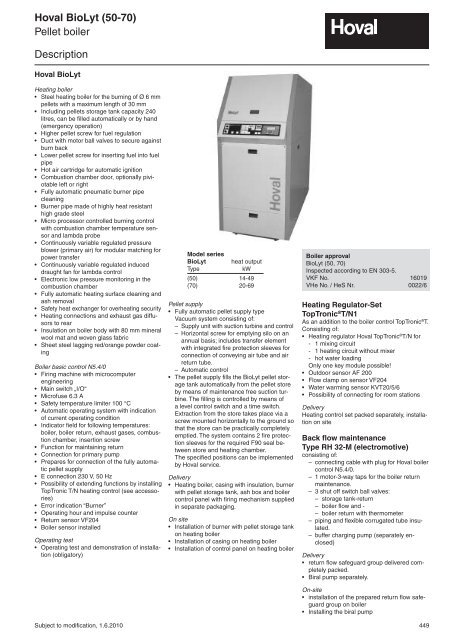
<strong>Hoval</strong> <strong>BioLyt</strong> (<strong>50</strong>-<strong>70</strong>)<strong>Pellet</strong> <strong>boiler</strong><strong>Description</strong><strong>Hoval</strong> <strong>BioLyt</strong>Heating <strong>boiler</strong>• Steel heating <strong>boiler</strong> for the burning of Ø 6 mmpellets with a maximum length of 30 mm• Including pellets storage tank capacity 240litres, can be filled automatically or by hand(emergency operation)• Higher pellet screw for fuel regulation• Duct with motor ball valves to secure againstburn back• Lower pellet screw for inserting fuel into fuelpipe• Hot air cartridge for automatic ignition• Combustion chamber door, optionally piviotableleft or right• Fully automatic pneumatic burner pipeclean ing• Burner pipe made of highly heat resistanthigh grade steel• Micro processor controlled burning controlwith combustion chamber temperature sensorand lambda probe• Continuously variable regulated pressureblower (primary air) for modular matching forpower transfer• Continuously variable regulated induceddraught fan for lambda control• Electronic low pressure monitoring in thecom bustion chamber• Fully automatic heating surface cleaning andash removal• Safety heat exchanger for overheating security• Heating connections and exhaust gas diffusorsto rear• Insulation on <strong>boiler</strong> body with 80 mm mineralwool mat and woven glass fabric• Sheet steel lagging red/orange powder coatingBoiler basic control N5.4/0• Firing machine with microcomputerengineer ing• Main switch „I/O“• Microfuse 6.3 A• Safety temperature limiter 100 °C• Automatic operating system with indicationof current operating condition• Indicator field for following temperatures:<strong>boiler</strong>, <strong>boiler</strong> return, exhaust gases, combustionchamber, insertion screw• Function for maintaining return• Connection for primary pump• Prepares for connection of the fully automaticpellet supply• E connection 230 V, <strong>50</strong> Hz• Possibility of extending functions by installingTopTronic T/N heating control (see accessories)• Error indication “Burner”• Operating hour and impulse counter• Return sensor VF204• Boiler sensor installedOperating test• Operating test and demonstration of installation(obligatory)Subject to modification, 1.6.2010Model series<strong>BioLyt</strong> heat outputTypekW(<strong>50</strong>) 14-49(<strong>70</strong>) 20-69<strong>Pellet</strong> supply• Fully automatic pellet supply typeVacuum system consisting of:– Supply unit with suction turbine and control– Horizontal screw for emptying silo on anannual basis; includes transfer elementwith integrated fire protection sleeves forconnection of conveying air tube and airreturn tube.– Automatic control• The pellet supply fills the <strong>BioLyt</strong> pellet storagetank automatically from the pellet storeby means of maintenance free suction turbine.The filling is controlled by means ofa level control switch and a time switch.Ex trac tion from the store takes place via ascrew mounted horizontally to the ground sothat the store can be practically completelyemptied. The system contains 2 fire protectionsleeves for the required F90 seal betweenstore and heating chamber.The specified positions can be implementedby <strong>Hoval</strong> service.Delivery• Heating <strong>boiler</strong>, casing with insulation, burnerwith pellet storage tank, ash box and <strong>boiler</strong>control panel with firing mechanism suppliedin separate packaging.On site• Installation of burner with pellet storage tankon heating <strong>boiler</strong>• Installation of casing on heating <strong>boiler</strong>• Installation of control panel on heating <strong>boiler</strong>Boiler approval<strong>BioLyt</strong> (<strong>50</strong>, <strong>70</strong>)Inspected according to EN 303-5.VKF No. 16019VHe No. / HeS Nr. 0022/6Heating Regulator-SetTopTronic ® T/N1As an addition to the <strong>boiler</strong> control TopTronic ® T.Consisting of:• Heating regulator <strong>Hoval</strong> TopTronic ® T/N for- 1 mixing circuit- 1 heating circuit without mixer- hot water loadingOnly one key module possible!• Outdoor sensor AF 200• Flow clamp on sensor VF204• Water warming sensor KVT20/5/6• Possibility of connecting for room stationsDeliveryHeating control set packed separately, installationon siteBack flow maintenanceType RH 32-M (electromotive)consisting of:– connecting cable with plug for <strong>Hoval</strong> <strong>boiler</strong>control N5.4/0.– 1 motor-3-way taps for the <strong>boiler</strong> returnmaintenance.– 3 shut off switch ball valves:– storage tank-return– <strong>boiler</strong> flow and -– <strong>boiler</strong> return with thermometer– piping and flexible corrugated tube insulated.– buffer charging pump (separately enclosed)Delivery• return flow safeguard group delivered completelypacked.• Biral pump separately.On-site• installation of the prepared return flow safeguardgroup on <strong>boiler</strong>• Installing the biral pump449
<strong>Hoval</strong> <strong>BioLyt</strong> (<strong>50</strong>-<strong>70</strong>)Part N°AccessoriesPart no.CHFCleaning set to <strong>BioLyt</strong> (<strong>50</strong>,<strong>70</strong>)consists of:Ash shovel, brush and ash scrapers with consolemurale and mounting material as well aspower cable for the manual operation of theex traction fan 6015 844 XXX.–Suction turbinefor wall mountingCentrifugal separatorset up on <strong>boiler</strong>Basic kit RAS 41For automatic transfer of pellets from the stor -age system (store, cloth silo or pellet tank) in tothe <strong>BioLyt</strong> pellet box. Consisting of suction turbinefor wall mounting and centrifugal separatorsetting up on the pellets box of the <strong>BioLyt</strong>.Filling is time controlled and via level indicator.6014 644 1‘840.–<strong>Pellet</strong> storage systemssee separate chapterMaximum distanceOutput length [m]maximum possibleoutput height [m]15 to 25 1,810 to 15 2,85 to 10 4,5Sound absorbing hood for suction turbinefor sound reductionDimensions:H x B x T = 710 x <strong>50</strong>0 x 354 mm 6018 717 xxx.–Subject to modification, 1.6.2010451
MMMM<strong>Hoval</strong> <strong>BioLyt</strong> (<strong>50</strong>-<strong>70</strong>)Part N°Accessories for TopTronic ® Theating regulation systemPart no.CHF1-7Key modules <strong>Hoval</strong> TopTronic ® Tfor further functions in addition to the standardfunctions.Key module consisting of:Function key to plug in TopTronic ® T includingaccessoriesOnly one key module possible!Standard functionsalready included in TopTronic ® T .- 1 mixing circuit- Domestic hot water loading circuitFunctions of the Key ModulesKey 2 Mixer- solid fuel solarModule circuit bivalent1234567M1Key module 1for 2 mixing circuitFunction key 1, flow sensor, 2 loose plugs6012 154 337.–2Key module 2for solid fuel/storage tank/bivalent installationFunction key 2, immersion sensors, 4 loose plugs6012 155 306.–3Key module 3for solar plantsFunction key 3, 1 collector sensor, 1 calorifiersensor, 4 loose plugs6012 156 286.–M4Key module 4for 2 mixing circuit and solid fuel/ storage tank/bivalent plantFunction key 4, 1 flow sensor, 3 immersion sensors,6 loose plugs6012 157 643.–M5Key module 5for 2 mixing circuit and solar plantsFunction key 5, 1 flow sensor sensor, 1 collectorsensor, 1 calorifier sensor, 6 loose plugs6012 158 622.–6Key module 6for solid fuel/storage tank/bivalent installation andsolar plantFunction key 6, 1 collector sensor, 4 immersionsensors, 6 loose plugs6012 159 592.–M7Key module 7for 2 mixing circuit ,solid fuel/storage tank/bivalentinstallation and solar plantFunction key 7, 1 flow sensor, 1 collector sensor,4 calorifier sensors, 8 loose plugs6012 160 928.–System solutions and applicationssee <strong>Hoval</strong> CDSensor typesImmersion-/ : Typ KVT20/5/6 (L = 5 m)calorifier sensor without immersion sleeveFlow sensor : Type VF204S with plugCollector sensor : Type PT1000 (Silicon)452Subject to modification, 1.6.2010
<strong>Hoval</strong> <strong>BioLyt</strong> (<strong>50</strong>-<strong>70</strong>)Part N°Accessories for TopTronic ® Theating regulation systemPart no.CHFRoom station RS-Teffective on one mixing circuit depending uponparameters, with room sensor, information-,program - and correction keys2034 939 255.–Remote control RFF-Teffective on a mixing circuit with room sensor,simple programme switch and temperature setter(+/- 6 K)2022 239 128.–Additional external control sensor AF 200effective on a mixing circuit or to averaging (2 externaltemperature sensors per regulator possible)2022 995 66.–Exhaust temperature sensor PT 1000/4includes securing screws (mounting on site)691 357 108.–Cable sensor KVT 20/5/6with 5 m cable2022 992 66.–Clamp on sensor VF 204can be used as flow or back flow sensor with4 m cable2023 998 66.–Flow temperature controllerfor floor heating (per heating circuit 1 controller)15-95 °C, SD 6 K, capillary max. <strong>70</strong>0mmset ting (visible externally) under the casingcover,Clamp on thermostat RAK-TW1000.SThermostat with retaining strap, without cableand plugImmersion thermostat RAK-TW1000.S SB1<strong>50</strong>Thermostat with immersion sleeve ½" - immersiondepth 1<strong>50</strong> mm nickel plated brass242 902 129.–6010 082 155.–Subject to modification, 1.6.2010453
<strong>Hoval</strong> <strong>BioLyt</strong> (<strong>50</strong>-<strong>70</strong>)Part N°AccessoriesPart no.CHFSafety set SG15-1“complete with safety valve (3 bar), pressuregauge and automatic air vent with cut off valveDN 15: connection Rp 1“application range up to <strong>50</strong> kW 641 184 44,<strong>50</strong>DN20: connection Rp1“application range up to 100 kW 6014 390 69,<strong>70</strong>Thermal flow safeguard STS20Valve ¾ ", with capillary tube 1.3m, immersionsleeve ½" - 142 mm. 242 662 202.–AABack flow maintenanceType RH 32-M (electromotive)Biral loading pump with cable for connection to<strong>boiler</strong> control, motor 3-way valvewith Biral pump (separately enclosed)for <strong>BioLyt</strong> (<strong>50</strong>,<strong>70</strong>) MX13-1 6022 627 788,00for <strong>BioLyt</strong> (<strong>70</strong>) M14-1 6022 629 938,00with mini-energy pump (separately enclosed)for <strong>BioLyt</strong> (<strong>50</strong>) AX13-1 6022 628 968,00for <strong>BioLyt</strong> (<strong>70</strong>) A14-1 6022 630 1.348,00Damperincluding explosion door and 90° t piece ofstainless steelinternal diameterTypesuitable for[mm]ZET 1<strong>50</strong> 1<strong>50</strong> <strong>BioLyt</strong> (<strong>50</strong>,<strong>70</strong>) 6008 032 281,00ZET 180 180 <strong>BioLyt</strong> (<strong>50</strong>,<strong>70</strong>) 6008 033 324,00The size of the damper is based uponthe dimension of the flue gas system.The lat ter has to be calculated.454Subject to modification, 1.6.2010
<strong>Hoval</strong> <strong>BioLyt</strong> (<strong>50</strong>-<strong>70</strong>)Technical Data<strong>Hoval</strong> <strong>BioLyt</strong>Type (<strong>50</strong>) (<strong>70</strong>)• Nominal output kW 49 69• Daily output 3 approx. kWh 1100 1400• Heat input at nominal output kW 54 74• Heat output area kW 14-49 20-69• <strong>Pellet</strong>s Ø mm 6-8 6-8Length mm 5-30 5-30• Maximum <strong>boiler</strong> flow temperature °C 80 80• Minimum <strong>boiler</strong> operating temperature °C 60 60• Minimum <strong>boiler</strong> back flow temperature °C 45 45• Exhaust temperature with nominal output °C 1<strong>70</strong> 1<strong>70</strong>• Exhaust temperature with lowest nominal output °C 90 90• Carbon dioxide CO 2% 12 12• Operating-/test pressure bar 3,0/4,5 3,0/4,5• Boiler efficiency at nominal output % > 90 > 90• Exhaust mass flow rate at nominal output watercontent of pellets 10 %kg/h 120 1<strong>70</strong>• Exhaust mass flow rate at lowest nominal output kg/h 38 53• Flow resistance pellets<strong>boiler</strong> z-value 1,5 1,5• upstream resistance at 10 K mbar 25 55• upstream resistance at 20 K mbar 7 16• Water flow at 10 K m³/h 4,2 6,4• Water flow at 20 K m³/h 2,1 3,2• Boiler water content Liter 180 215• Fuel-loading chamber capacity Liter 240 240• Ash area capacity Liter 65 65• Thickness of insulation of <strong>boiler</strong> body mm 80 80• Boiler weight(without lagging, burner, pellets hopper) kg 390 520• Boiler weight(with lagging, burner, pellets hopper) kg 640 780Thermal flow safeguard• Switching point of thermal flow safeguard °C 95 95• Minimal flow of water(cold water 10 °C)m³/h 2,0 2,0• Minimum required cold water flow pressure bar 2 2Exhaust plant 1• minimum downward <strong>boiler</strong> pressure Pa 5 5• Electrical intake capacity in operation Watt 1<strong>70</strong> 1<strong>70</strong>• Electrical intake capacity during ignition Watt 1800 1800• Electrical intake capacity during introduction of pellets Watt 1900 1900• Maximum current intake 2 A 13 131The installation of a damper is generally recommended.If there is a flue draught of over 20 Pa it is compulsory.Explosion door is required.2Min. 13 A protection because of operating current.3Taking account of the filling periodsPumping system basic kit type RAS 41Output length [m]maximum possibleoutput height [m]15 bis 25 1,810 bis 15 2,85 bis 10 4,5Subject to modification, 1.6.2010455
<strong>Hoval</strong> <strong>BioLyt</strong> (<strong>50</strong>-<strong>70</strong>)DimensionsMeasurements and space requirements for maintenance(all measurements in mm)min. ceiling height = H1 + 200mmmin.1 <strong>boiler</strong> flow R 1¼"2 <strong>boiler</strong> return R 1¼"3 RAS centrifugal separator ∅ <strong>50</strong> mm<strong>Pellet</strong> feed (accessories)4 safety heat exchanger 2 x R ½"5 draining R ¾"6 exhaust gas external Ø 1<strong>50</strong> mm7 suction ventilator8 electric control9 viewing glass10 sleeve for <strong>boiler</strong> sensor Rp ¾"11 sleeve for sensor of thermalflow safeguard Rp ½"<strong>BioLyt</strong>Type H1 H2 H3 B1 B2 E1 E2 E3(<strong>50</strong>) 1945 1<strong>70</strong>5 1545 740 640 1310 490 1290(<strong>70</strong>) 2025 1800 1635 800 740 1410 590 1385min.*min.** The heating <strong>boiler</strong> must be easily accessible on one side(left or right). The minimum measurements apply to oneside only.456Subject to modification, 1.6.2010
<strong>Hoval</strong> <strong>BioLyt</strong> (<strong>50</strong>-<strong>70</strong>)DimensionsPlacement measurements(all measurements in mm)Boiler depth 1220140HB1Wooden palletB21430<strong>BioLyt</strong>Type H B1 B2(<strong>50</strong>) 1790 640 740(<strong>70</strong>) 1880 740 840Subject to modification, 1.6.2010457
<strong>Hoval</strong> <strong>BioLyt</strong> (<strong>50</strong>-<strong>70</strong>)EngineeringStandards and guidelinesThe following standards and guidelines mustbe complied with:- <strong>Hoval</strong> technical information and installationinstructions.- Hydraulic and technical control regulations.- Local fire regulations as well as national regulations.- VKF fire protection regulations.- Regulations SWKI 97-1 „Water condition forheating, steam, cooling and air conditioningapparatus”.- Regulations SWK1.91-1 Ventilation and extractionof heating area.- Regulations SWK1-93-1 „Safety engineeringequipment for heating apparatus”.- Pay attention to SIA recommendationsNumber 384/4 „Chimneys for building heating,cross section identification”.- Regulations Procal/FKR “Plug in electricalconnections on <strong>boiler</strong>s and burners“.- Instruction leaflet –Procal „Corrosion throughhalogen connections“.- Procal instruction leaflet concerning „Corrosion damage in heating apparatus“ and brochure“Corrosion and <strong>boiler</strong> scale protectionin heating and service water installations”.- The LRV regulations must be adhered to.- Requirements for pellets in line with DIN/SN,Swisspellet, ÖNORM and PVA (<strong>Pellet</strong>sverbandAustria).Water qualityHeating water:- The European Standard EN 14868 and theDirective VDI 2035 must be observed. Inparticular, attention must be paid to the followingstipulations:-- <strong>Hoval</strong> <strong>boiler</strong>s and calorifiers are designedfor heating plants without significant oxygenintake (plant type I according to EN 14868).-- Plants with--continuous oxygen intake (e.g. underfloorheating systems without diffusion proofplastic piping) or--intermittent oxygen intake (e.g. wherefre quent refilling is necessary)must be equipped with separate circuits.-- Treated heating water must be tested atleast 1 x yearly. According to the inhibitorma nufacturer‘s instructions, more frequenttest ing may be necessary.Table 1: Maximal filling quantity based on VDI 2035-- A refilling is not necessary if the quality ofthe heating water in existing installations(e.g. exchange of <strong>boiler</strong>) conforms to VDI2035. The Directive VDI 2035 applies equallyto the replacement water.- New and if applicable existing installationsneed to be adequately cleaned and flushedbefore being filled. The <strong>boiler</strong> may only be filledafter the heating system has been flushed!- Parts of the <strong>boiler</strong> which have contact withwater are made of ferrous materials.- On account of the danger of stress crackingcorrosion the chloride, nitrate and sulphatecontents of the heating water must not exceed200 mg/l in total..- The pH value of the heating water shouldlie between 8.3 and 9.5 after 6 -12 weeks ofheating operation.Filling and replacement water:-- For a plant using <strong>Hoval</strong> <strong>boiler</strong>s untreateddrink ing water is generally best suited asheat ing medium, i.e. as filling and replacementwater. However, the water quality ofthe untreated drinking water must ful fil thestandard set in VDI 2035. Should the mainswater available not be suited for use then itmust be desalinated and/ or be treated withinhibitors. The stipulations of EN 14868 mustbe observed.-- In order to maintain a high level of <strong>boiler</strong>effi ciency and to avoid overheating of theheat ing surfaces the values given in the tableshould not be exceeded (dependent on<strong>boiler</strong> performance ratings - for multi-<strong>boiler</strong>plants rating of smallest <strong>boiler</strong> applies - andon the water content of the plant).-- The total amount of filling and replacementwater which is used throughout the total servicelife of the <strong>boiler</strong> must not exceed threetimes the water capacity of the plant.Heating System- The <strong>boiler</strong>s may not be set up in areas withhalogen compounds occur and may enterthe combustible air (e.g. washing, drying,workshop areas, hairdressing salons etc).- Halogen compounds can be caused byTotal hardness of filling water up to ..[mol/m 3 ] 1 3,0f°H 30d°H 16,8e°H 21,3~mg/l 300Conductance 2 600Boiler size ofindividual <strong>boiler</strong><strong>50</strong> to 200 kWNOREQUIREMENTmaximum filling quantity without demineralization<strong>50</strong> l/kW 20 l/kW 20 l/kW always desalinateclean ing, degreasing and solvent agents,ad hesives and bleaching liquids. Take noteof the Procal instruction leaflet, CorrosionThrough Halogen Compounds.- The heating area must comply with fire serviceregulations.- The heating area doors must be closed becausethe thermal buoyancy in the buildingcan lead to a drop in pressure which worksagainst the flue pressure.- The supply of combustion air must be guaranteed.The air supply opening must beplac ed in the zone of the main wind directionand there must be no possibility of closingit. Minimum air requirement 4.2 m 3 /h perkW <strong>boiler</strong> maximum capacity. Minimum freecross section for the air opening 13 cm 2 /kW.Space requirementssee separate dimensioned drawing.Energy storage deviceThe installation of an energy storage is generallyrecommended. For oversized <strong>boiler</strong>s(≥ 20 %) or if parts of the heat diffusion systemare often disconnected, a storage tank isimperative.For hot water generation a storage tank is necessaryin most cases. Standard size: 10 - 30litre/kW <strong>boiler</strong> output.An accurate determination of the plant dimensioningis necessary.Heating InstallationReturn maintenance- A <strong>boiler</strong> return maintenance must be providedto safeguard a minimum <strong>boiler</strong> returntem perature of 45 °C. Take note of the hydraulicapplication examples.Hydraulic operation- Take note of the application examplesHeat distribution- For room heating an automatic temperaturecontrol with one or several mixer circuitsmust be supplied.Plant with open expansion tank- The height of the apparatus must ensurethat the required minimum pressure inthe in take connection of the pump for theavoid ance of cavitation is reached (see catalogue“Biral Pumps”)Plant with pressure expansion tank<strong>Hoval</strong> <strong>BioLyt</strong> (<strong>50</strong>-<strong>70</strong>)- with inbuilt thermal flow feed safety device.- Inspected according to EN 303-5.- The expansion and safety engineeringequip ment necessary for the heating plantare to measured and applied outside the<strong>boiler</strong> according to engineering rules.1sum of alkaline earths2If the conductance in µS/cm exceeds the tabular value an analysis of the water is necessary.458Subject to modification, 1.6.2010
<strong>Hoval</strong> <strong>BioLyt</strong> (<strong>50</strong>-<strong>70</strong>)EngineeringSafety valveA safety valve and an automatic air bleedermust be installed on the flow.Thermal flow safeguardThe heat exchanger must be connected to thecold water supply at a minimum required flowpressure of 2 bar and minimum capacity<strong>BioLyt</strong> (<strong>50</strong>) 2000 l/h<strong>BioLyt</strong> (<strong>70</strong>) 2000 l/hFlue-/exhaust gas plantDamper and explosion door- The installation of an explosion door is compulsory.An explosion door must be installedin the connecting line or in the flue inside theheating area.Connecting pipe- The exhaust connecting pipe between theheating <strong>boiler</strong> and the flue must be connectedinto the flue at an angle of between 30and 45°.- If the length is greater than 1m insulation isrequired.- The fitting of the connecting pipe to the fluemust be carried out in such a way that nocon densation water can flow into the heatingboil er. Do not directly wall in exhaust pipebut connect it flexibly so that transmission ofnoise can be avoided.Flue plant- <strong>BioLyt</strong> downward pressure: min. 0.05 mbar- The exhaust plant must be unaffected bymois ture, acid resistant, emission burn resistantand suitable for exhaust temperaturesof <strong>70</strong>-160 °C.- With existing flue installations, the cleaningmust take place according to informationfrom the chimney builder.- Pay attention to SIA recommendation Number384/4 „Chimneys for building heating,cross section identification”.Non binding standard values for flue diameterThe following are standard values:A precise calculation of the output capacitymust take place.Fundamentals: Smooth wall flues made ofchrome steel pipe connecting pipe ≤ 2.5 m with0.5 m taper, 1 curve 90° and 1 angle 45°, Σζ= 0,8. Connecting pipe of same Ø as exhaustconnections of heating <strong>boiler</strong>, connecting pipeand flue with insulation 40 mm. Height abovesea level up to maximum 1000 m, externaltem perature -15 °C.<strong>BioLyt</strong> (<strong>50</strong>) (<strong>70</strong>)m Ø Ø6-25 180 200m = effective flue heightØ = minimum required flue diameter (mm)Connection of 2 <strong>Hoval</strong> <strong>BioLyt</strong> (<strong>50</strong>-75) to acommon chimneyIn principle, the separate connection of 2 independentchimneys is always the better solution.If this is not possible, the following criteria mustbe fulfiled when connecting 2 <strong>Hoval</strong> pellet <strong>boiler</strong>sof the series <strong>BioLyt</strong> (<strong>50</strong>-75) to a commonchimney:- A chimney calculation must exist as fulfilled,which evaulates all relevant conditions(above all, minimum draught need); to beobserved is (among other things) the greatlyincreased modulation area of a 2-<strong>boiler</strong>system.- A separate connection pipe must be run tothe chimney from both pellet <strong>boiler</strong>s; bothflue gas pipes may first meet in the verticalchimney (intersection each with 45°); a junctionbefore entry in the chimney per hosepiece or similar is not permitted.- Every connection pipe must be equippedwith its own combination door – damper protection/explosionprotection; Distance fromthe exhaust gas outlet of the <strong>boiler</strong> mustamount to at least 2x D.- When commissioning the <strong>boiler</strong>, the correctfunction of the exhaust system must bechecked and confirmed by <strong>Hoval</strong> factorycustomer service (according to internalinspection certificate).- The approval of the responsible regionalchimney sweeper must be present.Position:2xD2DD1D- A lockable exhaust measuring nozzle within ternal diameter of 10-21mm must be installedin the connecting pipe. The nozzle mustbe directed outwards via the insulation.DSubject to modification, 1.6.2010459
<strong>Hoval</strong> <strong>BioLyt</strong> (<strong>50</strong>-<strong>70</strong>)Examples<strong>Hoval</strong> <strong>BioLyt</strong> with permanent return flow safeguard, energy buffer storage tank,one or two heating groups and calorifier starting from distributorHydraulic plan BDDT0<strong>50</strong>AF24TopTronic TVF1B1VF2B1RS-TDHW WWTTTTMK1MK2YPDies ist einunerlaubter Weg!Gehen Sie einenSchritt zurück oderlöschen Sie diesesShape!Sie haben dieMöglichkeit <strong>BioLyt</strong> einneues Shape zunehmen!!! > <strong>50</strong>kWhovhovalhovalhovalhovalhovalhovalhovalhovalhovalhovalhovalhovalhovalhovalhovalhovavalhovalhovalhovaDies ist einunerlaubter Weg!Gehen Sie einenSchritt zurück Toder löschen Siedieses Shape!Sie haben dieMöglichkeit einneues Shape zunehmen!!!hovhovalhovalhovalhovalhovalhovalhovalhovalhovalhovalhovalhovalhovalhovalhovalhovalhovalhovalhovalhovalhovalhovalhovalhovalhovalhovalhovalhovalhovalhovalhovalhovalhovalhovalhovalhovalhovalhovalhovalhovalhovalhovalhovalhoPF1PF2YK1 MYK2MSLPSF1SF2Dies ist einunerlaubterWeg! TGehen Sieeinen Schrittzurück oderlöschen Siedieses Shape!Sie haben dieMöglichkeit einneues Shapezu nehmen!!!hovhovalhovalhovalhovalhovalhovalhovalhovalhovalhovalhovalhovalhovalhovalhovalhovalhovalhovalhovalhovalhovalhovalhovalhovalhovalhovalhovalhovalhovalhovalhBRU RLFPLPYKRDCW KWRS-TRoom stationAF Outdoor sensorVF1 Flow sensor 1VF2 Flow sensor 2PF1 Hot water tank sensor 1PF2 Hot water tank sensor 2SF 1 Water heater sensor 1SF 2 Water heater sensor 2B1 Flow temperature guard(if required)BRU Return sensorMK1 Pump mixer circuit 1MK2 Pump mixer circuit 2SLP Calorifier loading pumpPLP Buffer loading pumpYK1 Actuator mixer 1YK2 Actuator mixer 2YKR Actuator return mixerDCW Cold waterDHW Warm waterNotice:- This hydraulic schematic is a principlesche matic. It does not contain all detailsfor in stallation. The installation must bedone ac cording to local conditions, dimensioning and regulations- For underfloor heating, a flow temperaturemonitor must be built-in.- Shut-off devices to the safety valve(pres surized expansion tank, safetyvalve, etc.) are to safe against unintendedclosing!- Mount bags to prevent single pipe gravitycirculation.460Subject to modification, 1.6.2010