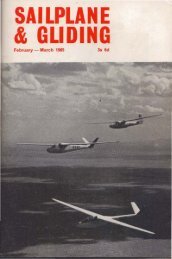
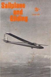
Fig 1 THE TRANSMITTERGLIDERRADIOCRYSTALOSCILLATORMULTIPLIERDRIVERMODULATORPOWERAMPLIFIER\J-3KHz +3KHz 1ICENTRE IFREQUENCY II6KHzBANDWIDTH [/COLlN DEWS, Chai'rman of the BGA Radio CommitteeFig 2With the introduction of 25Khz channel spacing in theaeronautical band and the almost certain probability thatduring 198 I the gliding movement will be assigned an additionalchannel (within the band 130.4-129.9Mhz) it willbecome increasingly important for us t~ use our radios efficienllyand responsibly.We shall need to consider very carefully how to make thehest use of the assigned radio channels and also make surethat our radio equipment is performing correctly.Perhaps the best place to start ,is at the beginning with somevery hasic radio principles before considering installations,licences. ccIII signs and procedures. This first al1ide hastherefnre been written for the reader with little or no knowledgeof radio.A Human Analogy. When we speak to each other as we sit inour living rooms oi· offices we use a system which is a'lmostanalogous to radio; wc create sound waves through our mouthswhich are modulated by the vocal cor,ds and the actions of thetongue (llld lips. These sound waves are transmitted through theair and a portion of this energy is collected by the ears of ourlistener. The ear drums detect the sound waves as vibration~and transmit these impulses .\0 the brain. The greater the distancebetween the speaker and the I'istener the smaller theenergy received by the ears of the listener.THE RADIO EQUIPMENTTile Transmitter. The radio transmi\ler is basical')y agenerator of h,igh frequency alternating current. This current isfed into aA aerial system eO:lbling the current to oscillate up anddown the aerial. The energy in the aerial produces an electromagneticfield which leaves lhe aerial in the forf,n of electromagneticwaves. We refer to this energy as the carrier waveand it can be likened (0 the flow of the air through the throat andmouth of a person speaking. In order to make the radio carrierwave carry intelligence, we need to modulate it with an electricalequivalent to our vocal cords. Sound waves used for telephoniccommunication cover 11 frequency range of approximately300 to 3000Hz and later we shal'l see the signiticance ofkeeping within this frequency range.(Hz is an
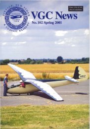
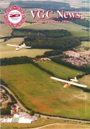
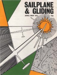
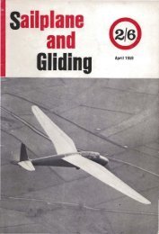
MIXERIF. FilTERINTERMEDIATEFREOUEHCVAUDIOAMPLIF1IiA DETECTOfl: "."-IFIEAFig 42nd RF AMPLIFIERIl3a:Fig 3iI has to select the "wanted" signal. it has to remain stable(exaclly on tune) and it has lo be sensitive ~ detecting signalsdown to one microvolt. If we tried to build a receiver as itstraighl VHF amplifier with a gain of several million it wouldsimply become unstable ,and regenerate (HOWL). The methodused to overcome t,hese problems is to change the frequency ofamplification to a lower order where all t.he circllils can beoptimised for gain and stability. This is achieved by mixing alocally generated signal from a very stable source - a crystalwiththe incoming wanted signal to produce an intermediatefrequency signal which is significantl:y lower i,n frequency thanthe received signal. This is the principle of the SuperHeterodyne receiver (Superhet) and it is almost exclusivelyused in communication receivers,. In some VH F communica·tions, receivers where ex,treme selecli'vity (rejection of the adjacentchannels) is required, the fl'equency is changed twice toproduce a double Superhet.In the receiver diagram, Fig 3, the input from the aerial,which contains both wanted and unwanted signals, is applied toone or two stages of amplification, each one being "tuned" toallow only a narrow band of frequencies around the "wanted"frequency to filter through.Radio Frequency Amplifier Stages. As an example, if ourrecei,ver was designed to receive 130.4MHz, the first radio ~requencyamplifier may have a response curve with Cl band widthof 5MHz. See Filg 4.The second radio frequency amplifier reduces this bandwidthto approximately IM Hz, giving a respQltse curve with muchsteeper sides and also amplifying the signa3 many times beforeapplying il to what is termed the mixer stage.Mixer. The mixer stage has two inputs, the incoming signalfrom the RF amplifier and a signal! which is generated by thelocal crystal oscillator. The two signals "beat" together in themixer andtne Qutput contains not only the or.iginal pair of frequenciesbut two new frequencies which are the sum and thedilTerence of the original pair, This effect ,is demonstrated f"equenl!ywhen we listen in on our gliding channels and hear twoor more transmissi'ons simultaneously - the howls, whistlesand groans are the' 'audio difference" frequenc,ies of the incomingsignals.In this examp1e the intermediate frequency chosen isIO.7MHz which is fairly common in modern VHF receivers.If our radiowas arranged to receive 130.4MHz the local crystaloscillator may operate at 39.9MHz and its oulput mulliplied byx3 to produce an input to the mixer stage of 119.7MHz. Thislocally generated signal when mixed with the incoming signalfrom the RF amplifier of 130.4MHz would produce 250.I'MHzand IO.7MHz. Because of the significant difference in freQuency between these signals it is rdatively easy 10 select thedesired intermediate frequency (IO.7MHz) and apply this signalto a very selective filter.<strong>Feb</strong>ruary/<strong>Mar</strong>ch 1981J:1 MHZi.FREQUEN,C~~f----- 5MHz -----1~The Intermediate F,requency Filter. This fi:Iter is designed topass only a narrow band of freq,uellcies around IO.7MHz. It ,isconstructed of six or eight tUlled circuits with individual staggeredrespoAses as shown in F,ig 5. The net result is a filter withINTERMEDlAl'EFREQUENCY FILTER CURVEIIIII "I I,II ~I ,I " ,I I , '\1 '\/ ,I \./
- Page 1 and 2: February-March 198195p
- Page 3 and 4: Magazine of the BRITISH GLIDING ASS
- Page 5 and 6: Flew Tech"olQg~ARE YOU READY FOR TH
- Page 7 and 8: ·CUT THE COST OF FLYINGINSURE WITH
- Page 9 and 10: Henry, a marine geologist in theIns
- Page 11: The Cautio-d"·1. A Nice,QuietBy ME
- Page 15 and 16: KRONFELD'S.SECRETVARIOMETERA. E. SL
- Page 17 and 18: LILIENTHAL DIAGRAMSWILLlAM MALPASPe
- Page 19 and 20: A LOAD OF BULL"A reluctant gliding
- Page 21 and 22: no sense a't all 10 have your only
- Page 23 and 24: the bar or half-way up the runway,
- Page 25 and 26: DORSET GOES DUTCH()ENNIS NEAL write
- Page 27 and 28: Another I'etter in the last S&G ("T
- Page 29 and 30: in the days before audio variometer
- Page 31 and 32: 0, B, ""mey Cranwell 30,9 5724 J, C
- Page 33 and 34: ANNUAL STATISTICS - OCTOBER 1, 1979
- Page 35 and 36: FLY FRIENDLYFLY THENORTHERNS25th Ju
- Page 37 and 38: work on club aircraft ourselves to
- Page 39 and 40: ULSTER (Bellarena, Co Derry)Gliding
- Page 41 and 42: tlours on the same night. Altogethe
- Page 43 and 44: wishes to experiment witn more up-t
- Page 45 and 46: very emotive happenin,gs, particula
- Page 47 and 48: REPLOGLEBAROGRAPHSF 24A MOTOR SPATZ
- Page 49 and 50: LS3·17 (LS3 with tips). Comp No50.
- Page 51 and 52: SHOBDONYour easily accessible wave