esponse curve should have verticill sides with all abrupt cut offat the base. In practice. the base of I'he response curve of thefilter has a "skirt" spreading the bandwidth a '~lIntlher J or 4KHzwith exponelltially 'tlecreasing gain.In effect a 'long "skirt" on the filter response curve. increasesthe probability of strong unwanled signals being acceptedbecause once tliley have passed through the filter even at a lowlevel of gain they will be ampldied hy the following stages of thereceiver. This point wi,1I become significant to users, of oldertype equipment particularly where the local a,irfield ATe hasbeen lIssigned an adjacent channel. (At the new 25KHzspa6ng), IJ'l this context glider folk who continue to lIsereceivers designed for operating on the 50K Hz channel spacingmay expect some interference from local stations as describedabove because the I F filter band width may in some cases bewide,.Tlle Intermediate Frequency Amplifier,. So far we have convertedour incoffi,ing signal of IJO.4MHz with all its speechcharacteris,tics in the form of side bamls into a lo'wer frequencysignal of IO.7MlHz. which contains the same side band characteristics.After the fiher, this signal is applied to a series ofpre-tuned amplifiers which are ,individwally fully screened anddesigned for optimum gain and 'bandwidth. The output is del'iveredfrom these amplifiers to a s'tage call1ed a "detector" ord~modulator.The .Detector. This stage simply removes one half of the moo,IIation envelope completely and filters off the now unwanted10.7MHz intermediate c,Jrri~r frequency as sh0wn in Fig 7. TheFig 7llDll VDETECTORSTAG&OUTPUTSPEECIiI SIGNAl:.+ DC COMPONENTTO OPERATt! A.O.CAND MUTEaudiosignal is then passed to an audio amplifier which enel:g,isesthe loudspeaker.Automatic Gain Control. Various refinements are ,incorporatedill the receiver such as "automatic gain control" and thisis achieved by taking some 0f the detected signal and convertingit into a "negative" bias which can be introduced to the earlierstages of RF' and IF amplification. Strong and very strong signalsare therefore automatically t:educed to a comforlable levelwithout signi,ficantly reducing the sensitivity of the receiver toweak signals.<strong>No</strong>ise Limiter. This consists of a circuit which w,ill pass up to,bU'1 not more than, a certain amplitude of signal and it effectivelysuppresses pulse type interference such as that caused byignition systems on vehicles or aircraft.Mute or Squeleh. Because there are many stages of gain in thereceiver an inherent "noise" is generated which may result inan irnitating hiss from the loudspeaker. This noise is worsenedby the effect of very we
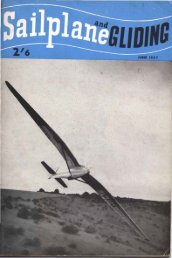
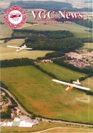
KRONFELD'S.SECRETVARIOMETERA. E. SLATERDoe Slater took ll,e.e piClllre. ofKronfeld andhi. erew on August 6. /928.In his article in the October ,issue (p228) on RQbert Kronfeld'sclandestine use of a variometer, Peter Riedel suggests that :thiswas firsl done on August 6, 1928, when Kronfeld made an .out·and-return flight in cloud Itft from the Wasserkuppe to Himmeldankberg.and back, nine miles in all, "without the benefit ofs'lope currents".I was present at the time Oil my first visit to a GermanNational contest. I watched him for over an hour and tookphotographs, but missed ;;eeing his actual departure. As to"without 'benefit of slope currents", he certainly took precautionsto see that they 'lifted him as high as possible towards theclouds. On a promonlary called "Pferdkopr' his team wereassembled with an anemometer on a pole. Whenever they sawKronfetd approaching' overhead, somebody would read thewind speed in metres per seco.nd, the team leader would chalk iton a large sheet of metal and hold it over his head, and the restof the team would lie down head-to-foot to show the precisewind direction. Several cumulus clouds came over, with eachone's base covering a large area under which he wandered hereand there, but I never noticed him performing circles at al'l, letalone tight ones. This does not suggest that he was using avariometer. He returned to the Wasserkuppe against ,the windunder a -cloud street, though he says he deviated a little to oneside now and then in search of better lift, so he must have usedeither his altimeter or a variometer.Fittings not food?---------'--.---------Regarding Peler Riedel's slory that Kronfeld carried his variometer10 his glider in a bag, the version I heard on the Wasserkuppewas that he carried the vacuum flask openly passing iloff as his coffee, and the bag with the rest of'lhe fiUings wouldthen be assumed to contain food.As to the double glide across the Channel in June 1931, it isodd that Kronfeld should have chosen this occasion to telegraphthe Askania firm to say how well their variometerworked, because be had no occasion 10 use ,it. Even when hecrossed the French coast in fading 'light on his return journeyand had difficulty in lfinding St In,glevert in lhe dusk, theAskania could not have helped to keep him up while he lookedfor it because there could have been no thermals at thatl;ate hourand anyway he said it was too dark to read his instmrnents..Many German pilcts, says Peter Riedel, could not afford tobuy variometers so had to go without. The cost at that time wasthe equivalent of about £14: I remember the figure because Inearly got around to buying one for the London <strong>Gliding</strong> <strong>Club</strong>,whQse members seemed never t.o have heard of the thing, letalone realised its importance.As to Dr Lippisch"s offer to invent a variometer for Kronfeld,aOer telling him he ought to have one, I have read this jnan article by Kronfeld which I cannot now t!'ace. But it is hard<strong>Feb</strong>ruary/<strong>Mar</strong>ch 1'981to believe that, if Lippisch had invented one, he would have letKronfeld keep it a secret instead ofoffering the invention to theWhole gliding fraternity.Regarding Wolf Hir h's possible use of a variometer in hispioneer thermal fljght across country from Elrni.ra in October1930, his account makes no mention ofa variometer, tholJlgh hementions tile circling technique which he pioneered. He says hefound his first thermal by getting directly underneath anotherpilot who was far above everyone else; his next one by going towhere birds w.ere circling, and his last two by feeling a suddenupward heave ..-----'------------------------<strong>No</strong>t such a long intervalAs to Kronfeld not mentioning variometers in his book publishedin 19<strong>32</strong> four years after his Himmeldankberg flight, theinterval was not really so long; in July 1930" when he demonstratedto Ithe then Prince of Wales, he showed ttle Prince somediagrams he had already drawn for his "forthcoming" bookFinally, I agree with Peter Riedel that, in t.he interests ofhistory, the shortcomings of those who helped to make It, inwhatever activity, should not be for ever suppressed. As PhilipWill's used to say, "You don't have to be loopy in order to glide,but it helps". Such loopiness can ta'ke many forms, some ofthem hard~y publishable in the loopy one's :liJetime; yet I feelwilh him that quilrks of character which helped to mould thathistory shoul'd not for ever ~o unrecorded. How about writingthem up and putting tbem into a sealed envelope 'Iabe'lled "<strong>No</strong>tto be opened for x years"?Since writing the above, I have had a letter from Dennis Dawsonof Goring on Thames, referring to mention of a variometer,in the book <strong>Gliding</strong> and Sailplaning by Fritz Stamer, then headof the Wasserkuppe GI,iding School, and Alexander Lippisch,designer of a series of gliders and sailplanes from the Zoglingtrainer of 1926 to the Sao Paulo in which Heini Dittrnar won thefirst International Contest of 1937. This is a translation ofHandbuch fUr den Jungfiiegu published in Germany in 1929,and in a final chapter on instruments Lippisch mentions "aso-called variometer" that indicates ascent and descent and "ismuch used in balloons" but is "large and unwieldy and fails toregister immediately". Yet he does not add a word about ,theneed for such an instrument to register lhe actualt rate of ascentor descent, so it is impossible ,to believe that he had alreadyinvented such an instrument for Kronfeld the year before. Hemighl not even have realised the need for such a refinement,since Wollf H irth had not yet flown the world's first crosscountryin dry thermals; and Professor Georgii's 1923 book onsoar,ing meteorology, then still current; stated Ithat thermalswere too narrow and too weak to be used by sailplanes.A letter from R. Boyd of Preston points out that Kronfeld13
- Page 1 and 2: February-March 198195p
- Page 3 and 4: Magazine of the BRITISH GLIDING ASS
- Page 5 and 6: Flew Tech"olQg~ARE YOU READY FOR TH
- Page 7 and 8: ·CUT THE COST OF FLYINGINSURE WITH
- Page 9 and 10: Henry, a marine geologist in theIns
- Page 11 and 12: The Cautio-d"·1. A Nice,QuietBy ME
- Page 13: MIXERIF. FilTERINTERMEDIATEFREOUEHC
- Page 17 and 18: LILIENTHAL DIAGRAMSWILLlAM MALPASPe
- Page 19 and 20: A LOAD OF BULL"A reluctant gliding
- Page 21 and 22: no sense a't all 10 have your only
- Page 23 and 24: the bar or half-way up the runway,
- Page 25 and 26: DORSET GOES DUTCH()ENNIS NEAL write
- Page 27 and 28: Another I'etter in the last S&G ("T
- Page 29 and 30: in the days before audio variometer
- Page 31 and 32: 0, B, ""mey Cranwell 30,9 5724 J, C
- Page 33 and 34: ANNUAL STATISTICS - OCTOBER 1, 1979
- Page 35 and 36: FLY FRIENDLYFLY THENORTHERNS25th Ju
- Page 37 and 38: work on club aircraft ourselves to
- Page 39 and 40: ULSTER (Bellarena, Co Derry)Gliding
- Page 41 and 42: tlours on the same night. Altogethe
- Page 43 and 44: wishes to experiment witn more up-t
- Page 45 and 46: very emotive happenin,gs, particula
- Page 47 and 48: REPLOGLEBAROGRAPHSF 24A MOTOR SPATZ
- Page 49 and 50: LS3·17 (LS3 with tips). Comp No50.
- Page 51 and 52: SHOBDONYour easily accessible wave