Inverted Bucket Trap Capacity Chart - Armstrong International, Inc.
Inverted Bucket Trap Capacity Chart - Armstrong International, Inc.
Inverted Bucket Trap Capacity Chart - Armstrong International, Inc.
- No tags were found...

You also want an ePaper? Increase the reach of your titles
YUMPU automatically turns print PDFs into web optimized ePapers that Google loves.
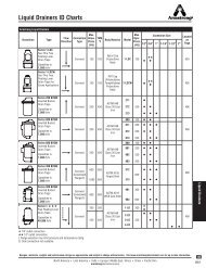
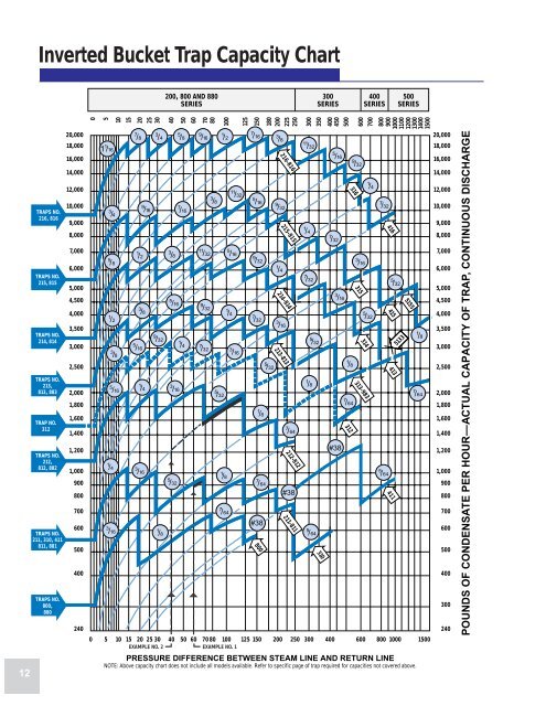
<strong>Inverted</strong> <strong>Bucket</strong> <strong>Trap</strong> <strong>Capacity</strong> <strong>Chart</strong>200, 800 AND 880SERIES300SERIES400SERIES500SERIES12TRAPS NO.216, 816TRAPS NO.215, 815TRAPS NO.214, 814TRAPS NO.213,813, 883TRAP NO.312TRAPS NO.212,812, 882TRAPS NO.211, 310, 411811, 881TRAPS NO.800,88020,00018,00016,00014,00012,00010,0009,0008,0007,0006,0005,0004,5004,0003,5003,0002,5002,0001,8001,6001,4001,2001,000900800700600500400240051 1 /163 /45 /81 /210152025303 /85 /161 /43 /167 /81 /23 /85 /161 /43 /169 /163 /49 /321 /84050603 /85 /163 /165 /325 /87 /161 /470809 /1611 /329 /327 /323 /85 /321001 /21 /87 /641 /411 /325 /163 /161251507 /165 /169 /327 /328001 /87 /64#381802002252503003504004505008009001000110012001300140015000 5 10 15 20 25 30 40 50 60 70 80 100 125 150 200 250 300 400 600 800 1000 1500EXAMPLE NO. 2EXAMPLE NO. 1PRESSURE DIFFERENCE BETWEEN STEAM LINE AND RETURN LINENOTE: Above capacity chart does not include all models available. Refer to specific page of trap required for capacities not covered above.5 /323 /8214-814213-813216-8169 /321 /4215-8153 /167 /64212-812#38211-81111 /321 /47 /321 /85 /325 /643105 /167 /323 /16#383123161 /87 /646009 /323 /16315314313-9837001 /45 /327 /324165 /644154134115 /32513351551 /87 /6420,00018,00016,00014,00012,00010,0009,0008,0007,0006,0005,0004,5004,0003,5003,0002,5002,0001,8001,6001,4001,2001,000900800700600500400300240POUNDS OF CONDENSATE PER HOUR—ACTUAL CAPACITY OF TRAP, CONTINUOUS DISCHARGE
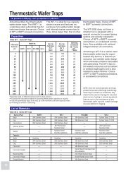
How to Use the <strong>Inverted</strong> <strong>Bucket</strong> <strong>Trap</strong> <strong>Capacity</strong> <strong>Chart</strong>This catalog should be utilized as aguide for the installation and operationof steam trapping equipment byexperienced personnel. Selection orinstallation should always be accompaniedby competent technicalassistance or advice. <strong>Armstrong</strong> andits local representatives are availablefor consultation and technical assistance.We encourage you to contactyour <strong>Armstrong</strong> representative forcomplete details.To select an inverted bucket steamtrap using the <strong>Armstrong</strong> capacitychart, you must know the condensateload, safety factor and pressuredifferential. Remember, the objectiveis always to select a trap that can1) operate at the maximum differentialpressure and 2) handle the capacityat the minimum differential pressure.Consider the following typical problems.EXAMPLE 1. Constant Pressure andCondensing RateGiven:Maximum pressure differential 70 psiOperating differential60 psiCondensate load 300 lbs/hrtimes 3:1 safety factor or 900 lbs/hrEnter chart at 60 psi line and go up to 900 lbs/hrcapacity. This is directly on the 5 /32" orifice lineas shown in Fig.13-1. The capacity of this 5 /32"orifice at pressures less than 30 psi is indicatedby the thin blue line. Follow the line to theright to the vertical drop at 70 psi. This meansthis orifice will operate to a maximum of 70 psidifferential—the other requirement for thisapplication. Follow the heavy line back to theleft and note that it’s attached to the arrowindicating that the 211, 811 or 881 traps withthe 5 /32" orifice will yield this capacity. This isthe trap to use.Figure 13-1.POUNDS OF CONDENSATE PER HOUR7500160012009006004000 30 60 70 125 200PRESSURE DIFFERENTIAL (PSIG)EXAMPLE 2. Constant Pressure andCondensing Rate but with Possible HighBack PressureAssume for example:Maximum pressure differential 90 psiOperating differential minimum 40 psiOperating differential normally 60 psiCondensate load 300 lbs/hrtimes 3:1 safety factor or 900 lbs/hrNote in Fig.13-1 that the 5 /32" orifice will handlethe 900 lbs/hr load at a differential pressureof 60 psi. When the operating differentialdrops to the minimum level (40 psi),however, the capacity is only 800 lbs/hr.To solve the problem, refer to the sawtoothchart. Enter at the minimum differentialpressure (40 psi) and move up until youintersect a line that is above 900 lbs/hrcapacity, which is the first thin blue lineabove the heavy blue “sawtooth” for the211, 811 and 881 traps. Note that this is thecontinuation of the capacity line for the 5 /32"orifice for the 212, 812 and 882 traps. Nowfollow the line to the right until the verticaldrop at 125 psi differential. This is within ourrequirement of 90 psi. Therefore a 5 /32" orificecan handle the 900 lbs/hr condensate loadwhen fitted into a 212, 812 or 882 trap andthat it will not lock shut at the 90 psi maximumdifferential. This is the trap to use sinceit will handle the load at both the minimumand maximum operating differentials, eventhough it has a maximum operating pressuredifferential of 125 psi.<strong>Inverted</strong> <strong>Bucket</strong> <strong>Capacity</strong> <strong>Chart</strong>How the <strong>Capacity</strong><strong>Chart</strong> Was MadeThe <strong>Armstrong</strong> capacity chart showscontinuous discharge capacities of<strong>Armstrong</strong> traps under actual operatingconditions as determined byliterally hundreds of tests. In thesetests condensate at the steam temperaturecorresponding to the testpressure was used. The chokingeffect of flash steam through theorifice, as well as the back pressurecreated by flash steam, wereautomatically taken into account.Actual installation hookups wereused so that pipe friction in bothinlet and discharge lines also werereflected in the results.<strong>Trap</strong> capacity ratings based on coldwater tests which produce no flashsteam would be much too high. Orificetests also are too high because theyignore pipe friction. Theoreticalcalculations of trap capacities havenever been conservative. You candepend on <strong>Armstrong</strong> capacityratings because they show actualcapacities of hot condensate.Heavy blue “sawtooth” curvesshow capacities for traps usingmaximum possible diameter orificesfor the pressures shown.Thin line curves extending downto the left of the heavy curves showthe capacities of <strong>Armstrong</strong> trapsat pressures below their maximumratings. For example: A No. 216trap, with 1 /2" orifice good for a maximumworking pressure of 125 psi,will have a continuous dischargecapacity of a little less than 12,000lbs/hr at 40 psi.Close study of this chart revealsthat steam trap capacity is governedby more than just the orifice diameter.A 2" No. 216 trap with 1 /2" dischargeorifice, working at 15 psi pressure,has a continuous discharge capacityof some 7,200 lbs/hr, but a 3 /4" No.213, also with 1 /2" orifice and alsoworking at 15 psi pressure, has acontinuous discharge capacity ofonly 3,900 lbs/hr. In the case of theNo. 213, friction in the 3 /4" pipe isgreatly restricting capacity, whereasthere is little capacity loss due topipe friction when a 1 /2" orifice isused in a 2" pipe at 15 psi.13