Type A - EN44, EN88 Installation Instructions - Dodge Engineering ...
Type A - EN44, EN88 Installation Instructions - Dodge Engineering ...
Type A - EN44, EN88 Installation Instructions - Dodge Engineering ...

Create successful ePaper yourself
Turn your PDF publications into a flip-book with our unique Google optimized e-Paper software.
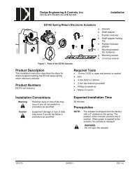
<strong>Dodge</strong> <strong>Engineering</strong> & Controls, Inc.Toll Free (877) 334-2875 Fax: (978) 244-1422<strong>Installation</strong><strong>EN44</strong> and <strong>EN88</strong> Non-Spring Return Electronic ActuatorsModulating Control, <strong>EN44</strong>B2 & <strong>EN88</strong>B21. Check that the wires are connected correctly.2. Check that the offset (start point) and span are set correctly, if used.3. Check that the direction of rotation switch matches the rotation of the damper shaft.4. Connect wires 1 (red) and 2 (black) to a Digital Multimeter (DMM) with the dial set at VAC to verify that theoperating voltage is within range.5. Check operation:a. Connect wires 1 (red) and 2 (black) to the actuator.b. Set the DMM dial to VDC.c. Connect wires 2 (black) and 8 (gray) to DMM.d. Apply a full scale input signal (10 VDC) to wire 8 (gray).e. Allow the actuator shaft coupling to rotate from 0° to 90°.f. Disconnect wire 8 (gray).The shaft coupling returns to the 0 position.6. Check feedback:a. Set the DMM dial to VDC.b. Attach wires 2 (black) and 9 (pink) to the DMM.c. Apply a full scale input signal to wire 8 (gray).The reading at the DMM should increase.d. Remove the signal from wire 8 (gray).The reading at the DMM should decrease and the actuator shaft coupling returns to the 0 position.7. Check the auxiliary switch A (-S option):a. Set the DMM dial to OHMS (resistance) or continuity check.b. Connect wires S1 and S3 to the DMM.The DMM should indicate an open circuit or no resistance.c. Apply a full scale input signal to wire 8 (gray).The DMM should indicate contact closure as the actuator shaft coupling reaches the setting of switch A.d. Connect wires S1 and S2 to the DMM.The DMM should indicate an open circuit or no resistance.e. Stop the signal to wire 8 (gray).The DMM should indicate contact closure as the actuator shaft coupling reaches the setting of switch A.8. Check the auxiliary switch B (-S option):a. Set the DMM dial to OHMS (resistance) or continuity check.b. Connect wires S4 and S6 to the DMM.The DMM should indicate an open circuit or no resistance.c. Apply a full scale input signal to wire 8 (gray).The DMM should indicate contact closure as the actuator shaft coupling reaches the setting of switch B.d. Connect wires S4 and S5 to the DMM.The DMM should indicate an open circuit or no resistance.e. Stop the signal to wire 8 (gray).The DMM should indicate contact closure as the actuator shaft coupling reaches the setting of switch B.129-271 EAI/EN4-11 DEI, Inc. Rev. 10/04Rev. 4, October, 2004