Type A - EN44, EN88 Installation Instructions - Dodge Engineering ...
Type A - EN44, EN88 Installation Instructions - Dodge Engineering ...
Type A - EN44, EN88 Installation Instructions - Dodge Engineering ...

Create successful ePaper yourself
Turn your PDF publications into a flip-book with our unique Google optimized e-Paper software.
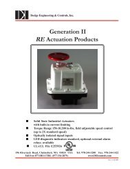
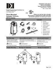
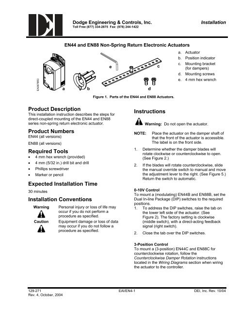
9090<strong>Dodge</strong> <strong>Engineering</strong> & Controls, Inc.Toll Free (877) 334-2875 Fax: (978) 244-1422<strong>Installation</strong><strong>EN44</strong> and <strong>EN88</strong> Non-Spring Return Electronic ActuatorsEA0678R345abedca. Actuatorb. Position indicatorc. Mounting bracket(for dampers)d. Mounting screwse. 4 mm hex wrenchFigure 1. Parts of the <strong>EN44</strong> and <strong>EN88</strong> Actuators.Product DescriptionThis installation instruction describes the steps fordirect-coupled mounting of the <strong>EN44</strong> and <strong>EN88</strong>series non-spring return electronic actuator.Product Numbers<strong>EN44</strong> (all versions)<strong>EN88</strong> (all versions)Required Tools• 4 mm hex wrench (provided)• 4 mm (5/32 in.) drill bit and drill• Phillips screwdriver• Marker or pencilExpected <strong>Installation</strong> Time30 minutes<strong>Installation</strong> ConventionsWarningCautionPersonal injury or loss of life mayoccur if you do not perform aprocedure as specified.Equipment damage or loss of datamay occur if you do not follow aprocedure as specified.<strong>Instructions</strong>NOTE:Warning: Do not open the actuator.Place the actuator on the damper shaft ofthat the front of the actuator is accessible.The label is on the front side.1. Determine whether the damper blades willrotate clockwise or counterclockwise to open.(See Figure 2.)2. If the blades will rotate counterclockwise, slidethe manual override switch to manual and movethe adjustment lever to the right. (See Figure 5.)Return the switch to automatic.0-10V ControlTo mount a (modulating) <strong>EN44</strong>B and <strong>EN88</strong>B, set theDual In-line Package (DIP) switches to the requiredpositions.1. To address the DIP switches, raise the tab onthe lower left side of the actuator. (SeeFigure 2). The factory setting is clockwise(middle switch), with a direct-acting feedbacksignal (right switch).2. Close the tab over the DIP switches.3-Position ControlTo mount a (3-position) <strong>EN44</strong>C and <strong>EN88</strong>C forcounterclockwise rotation, follow theCounterclockwise Damper Rotation instructionslocated in the Wiring Diagrams section when wiringthe actuator to the controller.129-271 EAI/EN4-1 DEI, Inc. Rev. 10/04Rev. 4, October, 2004
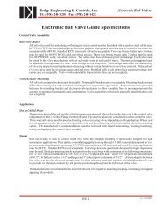
<strong>Dodge</strong> <strong>Engineering</strong> & Controls, Inc.Toll Free (877) 334-2875 Fax: (978) 244-1422<strong>Installation</strong><strong>Installation</strong><strong>EN44</strong> and <strong>EN88</strong> Non-Spring Return Electronic ActuatorsCLOCKWISETO OPEN"0"1COUNTERCLOCKWISETO OPEN90˚90˚245˚90˚2'45˚90˚self a daptself a dapt00self adaptself adaptPL0060R2only for:0-10V and 00-20 mACONTROL SIGNALS3only for:0-10V and 00-20 mACONTROL SIGNALSNOTE: For a direct-acting feedback signal to track the actuator position, set both DIP switches as shown.Figure 2. Setting Direction of Rotation.3'24 mm60-90 lb-in(7-10 Nm)Torque51b90904590459034EA0532R2EA0533R3Figure 3. Mounting the Actuator to the Damper Shaft.129-271 EAI/EN4-2 DEI, Inc. Rev. 10/04Rev. 4, October, 2004
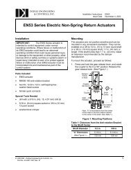
<strong>Dodge</strong> <strong>Engineering</strong> & Controls, Inc.Toll Free (877) 334-2875 Fax: (978) 244-1422<strong>Installation</strong><strong>EN44</strong> and <strong>EN88</strong> Non-Spring Return Electronic ActuatorsCENTER THEMOUNTING BRACKETIN THE SLOTCAUTION:THESE HOLES FOR USE WITHACCESSORY KITS ONLY. DO NOTUSE IN THE INSTALLATION OFDIRECT-COUPLED APPLICATIONS1/21/2∅4 mm5/32 in.cddEA0786R3Figure 4. Attaching the Mounting Bracket.Manual OverrideTo move the damper blades and lock in the positionwith no power present:1. Slide the red manual override switch toward theback of the actuator.2. Make adjustments to the damper position.3. Slide the red manual override switch toward thefront of the actuator.ADJUSTMENTLEVER902Once power is restored, the actuator returns toautomated control.4590MANUALPL0013R2AUTO31Figure 5. Manual Override.129-271 EAI/EN4-3 DEI, Inc. Rev. 10/04Rev. 4, October, 2004
<strong>Dodge</strong> <strong>Engineering</strong> & Controls, Inc.Toll Free (877) 334-2875 Fax: (978) 244-1422<strong>Installation</strong><strong>EN44</strong> and <strong>EN88</strong> Non-Spring Return Electronic ActuatorsMechanical Range Adjustment1. Loosen the stop set screw.2. Move the screw along the track to thedesired position, and fasten it in place.4 mm
<strong>Dodge</strong> <strong>Engineering</strong> & Controls, Inc.Toll Free (877) 334-2875 Fax: (978) 244-1422<strong>Installation</strong><strong>EN44</strong> and <strong>EN88</strong> Non-Spring Return Electronic ActuatorsDual Auxiliary Switch (-S option)Figure 8 shows the adjustable switching values for theAuxiliary switches A and B.Actuator Scale: clockwiseAdjustment range for Switches A and B:Setting interval: 5°Switching hysteresis: 2°Actuator Scale: counterclockwiseFactory Setting:NOTE:A = 5°B = 85°EA0640R1-2,5 0 10 20 30 70 80 90 92,5A0 10 20 30 70 8092,5 90 80 70 60 20 10 0 -2,5Figure 8. Adjustable Switching Values forthe Dual Auxiliary Switches.90BEA0636R1A ˚ B10 2080 70 60 50AUX SWITCHADJUSTMENTFigure 9.The auxiliary switch setting shafts rotate with the actuator. The scale is valid only when the actuator is inthe 0 position on clockwise motion.Use the long arm of the cross on the Aux Switch Adjustment (Figure 9) to point to the position ofswitch A. Use the narrower tab on the red ring to point to the position of switch B.Zero Span Control Signal Adjustment (-ZS option)<strong>EN44</strong>B2-ZS(-S) and<strong>EN88</strong>B2-ZS(-S) :For sequencing and theelectronic limitation of the angleof rotation.Use the U0 potentiometer to setthe offset (start point) between 0and 5 VDC.Use the ∆U potentiometer to setthe slope between 2 to 30 VDC.NOTE:The ∆U adjustment becomesvirtual when the offset and slopesetting is greater than 10 V. TheY input is limited to a maximumof 10 VDC. Above 10 V, theangle of rotation is reduced,providing the feature ofelectronic limitation of the angleof rotation.Ys [%]100EA0632R102 5 10 30 35 Y [V]∆UwU O1)4)∆U (max. 30 V)Figure 10.Ys Actuator position (100% = angle of rotation 90° *)Y Control input signalU0 Offset (start point)∆U Slope∆Uw Active voltage range (Ys change)* When the mechanical limitation of the angle ofrotation and self-adapt function are ON (100%does not equal 90°).3)2)YsUo U VSLOPE, U2 101630 24OFFSET, Uo0 12EA0633R235 4Figure 11.129-271 EAI/EN4-5 DEI, Inc. Rev. 10/04Rev. 4, October, 2004
<strong>Dodge</strong> <strong>Engineering</strong> & Controls, Inc.Toll Free (877) 334-2875 Fax: (978) 244-1422<strong>Installation</strong><strong>EN44</strong> and <strong>EN88</strong> Non-Spring Return Electronic Actuatorsself adaptEA0638R10The factory setting is clockwise.The direction of rotation switch should match the damper rotation movement.Figure 14.Direction ofRotation Switch.self adaptThe factory setting is direct acting.EA0639R10Figure 15.Output SignalSwitch.As the clockwise angle of rotation increases, the output voltage increases.If the direction of rotation is counterclockwise, the output signal switch should be set atreverse acting to match the direction of the rotation switch.Wiring24 VACAll wiring must conform to NEC and local codes and regulations. Use earth ground isolating step-down Class 2transformers. Do not use auto transformers. Determine the supply transformer rating by summing the total VA ofall actuators used. It is recommended that no more than 10 actuators be powered by one transformer.Warning:The switching outputs are rated maximum 24 VAC/24 VDC and a maximum 4A resistive (2Ainductive).Warning:<strong>Installation</strong>s requiringConformance:• All wiring for CE rated actuators must only be separated extra low voltage (SELV) or protectiveextra low voltage (PELV) per HD384-4-41.• Use safety isolating transformers (Class III transformer) per EN 61558. They must be rated for100% duty cycle.• Overcurrent protection for supply lines is maximum 10A.129-271 EAI/EN4-7 DEI, Inc. Rev. 10/04Rev. 4, October, 2004
<strong>Dodge</strong> <strong>Engineering</strong> & Controls, Inc.Toll Free (877) 334-2875 Fax: (978) 244-1422<strong>Installation</strong><strong>EN44</strong> and <strong>EN88</strong> Non-Spring Return Electronic ActuatorsWiring Diagrams<strong>EN44</strong>C2/<strong>EN88</strong>C2Two- and Three-Position Control(24 VAC)Direction of Damper Rotation (<strong>EN44</strong>C2/<strong>EN88</strong>C2)If the damper blades turn counterclockwise to open(CCW), reverse the 6 (violet) and 7 (orange) wires atthe controller.EA0282R16 7M1P1P2 P3 S1 S41000Figure 16.AS2 S37 (ORANGE)6 (VIOLET)1 (RED)BS5 S6Table 2. Two or Three-Position Control 24 VAC.StandardSymbolFunctionColorPlenum1 (+) Red6 Control signal clockwise Violet7 Control signal counterclockwise OrangeS1 Switch A Common BlackS2 Switch A N.C. BlackS3 Switch A N.O. BlackS4 Switch B Common BlackS5 Switch B N.C. BlackS6 Switch B N.O. BlackP1P2P3Feedback Potentiometer0 to 100% P1 - P2Feedback PotentiometerCommonFeedback Potentiometer100 to 0% P3 - P2BlackBlackBlackEA0635R2NEUT24Vac120 VacFigure 17.EARTH GROUNDISOLATING CLASS 2TRANSFORMER FOR24 Vac POWER: SAFETY ISOLATINGTRANSFORMERPER EN 60742Caution:• Do not wire different types of actuators(such as EN177C, EN310C orEN142C) in parallel with these models.• Do not use Form A relays.129-271 EAI/EN4-8 DEI, Inc. Rev. 10/04Rev. 4, October, 2004
<strong>Dodge</strong> <strong>Engineering</strong> & Controls, Inc.Toll Free (877) 334-2875 Fax: (978) 244-1422<strong>Installation</strong><strong>EN44</strong> and <strong>EN88</strong> Non-Spring Return Electronic Actuators<strong>EN44</strong>B2/<strong>EN88</strong>B2Modulating Control (24 VAC)(0-10 V or 0-20 mA *)EA0284R18M129Figure 18.AS1S2 S3BS4S5 S6Warning:Do not use tandem mount 0-20 mAactuators.* Add 500 ohm resister across pins 2 and 8 toaccept input signal of 0-20 mA.StandardSymbolTable 2. Modulating Control 24 VAC.Function1 (+) Red2 Com Black8 0 to 10 V input signal or0 to 20 mA9 Output for 0 to 10 VDCposition indicationGrayPinkS1 Switch A Common BlackS2 Switch A N.C. BlackS3 Switch A N.O. BlackS4 Switch B Common BlackS5 Switch B N.C. BlackS6 Switch B N.O. BlackColorPlenum129-271 EAI/EN4-9 DEI, Inc. Rev. 10/04Rev. 4, October, 2004
<strong>Dodge</strong> <strong>Engineering</strong> & Controls, Inc.Toll Free (877) 334-2875 Fax: (978) 244-1422<strong>Installation</strong>Start-Up/Commissioning<strong>EN44</strong> and <strong>EN88</strong> Non-Spring Return Electronic ActuatorsTwo or Three-Position Control, <strong>EN44</strong>C2 and <strong>EN88</strong>C21. Check that the wires are connected correctly.2. Connect wires 1 (red) and 6 (violet) to a Digital Multimeter (DMM) with the dial set at VAC. Apply a controlsignal (24 VAC) to wire 6 to verify that the operating voltage is within range.3. Connect wires 1 (red) and 7 (orange) to a DMM with the dial set at VAC. Apply a control signal (24 VAC) towire 7 to verify that the operating voltage is within range.4. Check operation:a. Connect wire 1 (red) to the actuator.b. Apply a control signal (24 VAC) to wire 6 (violet).c. Allow the actuator shaft coupling to rotate from 0 to 90°.d. Stop applying a control signal to wire 6 (violet).e. Apply a control signal (24 VAC) to wire 7 (orange).f. Allow the actuator shaft coupling to rotate from 90 to 0°.5. Check feedback:a. Set the DMM dial to OHMS.b. Connect wires P1 and P2 to the DMM. The DMM should indicate a resistive value.c. Apply a control signal (24 VAC) to wire 6 (violet).d. The reading of the DMM should increase.e. Connect wires P2 and P3 to the DMM. The DMM should indicate a resistive value.f. Apply a control signal (24 VAC) to wire 7 (orange).g. The reading of the DMM should increase.6. Check the auxiliary switch A (-S option):a. Set the DMM dial to OHMS (resistance) or continuity check.b. Connect wires S1 and S3 to the DMM. The DMM should indicate an open circuit or no resistance.c. Apply a 24 VAC signal to wire 6 (violet).d. The DMM should indicate contact closure as the actuator shaft coupling reaches the setting of switch A.e. Stop applying a control signal to wire 6 (violet).f. Connect wires S1 and S2 to the DMM. The DMM should indicate an open circuit or no resistance.g. Apply a 24 VAC signal to wire 7 (orange).h. The DMM should indicate contact closure as the actuator shaft coupling reaches the setting of switch A.7. Check the auxiliary switch B (-S option):a. Set the DMM dial to OHMS (resistance) or continuity check.b. Connect wires S4 and S6 to the DMM. The DMM should indicate an open circuit or no resistance.c. Apply a 24 VAC signal to wire 6 (violet).d. The DMM should indicate contact closure as the actuator shaft coupling reaches the setting of switch B.e. Connect wires S4 and S5 to the DMM. The DMM should indicate an open circuit or no resistance.f. Apply a 24 VAC signal to wire 7 (orange).g. The DMM should indicate contact closure as the actuator shaft coupling reaches the setting of switch B.129-271 EAI/EN4-10 DEI, Inc. Rev. 10/04Rev. 4, October, 2004
<strong>Dodge</strong> <strong>Engineering</strong> & Controls, Inc.Toll Free (877) 334-2875 Fax: (978) 244-1422<strong>Installation</strong><strong>EN44</strong> and <strong>EN88</strong> Non-Spring Return Electronic ActuatorsModulating Control, <strong>EN44</strong>B2 & <strong>EN88</strong>B21. Check that the wires are connected correctly.2. Check that the offset (start point) and span are set correctly, if used.3. Check that the direction of rotation switch matches the rotation of the damper shaft.4. Connect wires 1 (red) and 2 (black) to a Digital Multimeter (DMM) with the dial set at VAC to verify that theoperating voltage is within range.5. Check operation:a. Connect wires 1 (red) and 2 (black) to the actuator.b. Set the DMM dial to VDC.c. Connect wires 2 (black) and 8 (gray) to DMM.d. Apply a full scale input signal (10 VDC) to wire 8 (gray).e. Allow the actuator shaft coupling to rotate from 0° to 90°.f. Disconnect wire 8 (gray).The shaft coupling returns to the 0 position.6. Check feedback:a. Set the DMM dial to VDC.b. Attach wires 2 (black) and 9 (pink) to the DMM.c. Apply a full scale input signal to wire 8 (gray).The reading at the DMM should increase.d. Remove the signal from wire 8 (gray).The reading at the DMM should decrease and the actuator shaft coupling returns to the 0 position.7. Check the auxiliary switch A (-S option):a. Set the DMM dial to OHMS (resistance) or continuity check.b. Connect wires S1 and S3 to the DMM.The DMM should indicate an open circuit or no resistance.c. Apply a full scale input signal to wire 8 (gray).The DMM should indicate contact closure as the actuator shaft coupling reaches the setting of switch A.d. Connect wires S1 and S2 to the DMM.The DMM should indicate an open circuit or no resistance.e. Stop the signal to wire 8 (gray).The DMM should indicate contact closure as the actuator shaft coupling reaches the setting of switch A.8. Check the auxiliary switch B (-S option):a. Set the DMM dial to OHMS (resistance) or continuity check.b. Connect wires S4 and S6 to the DMM.The DMM should indicate an open circuit or no resistance.c. Apply a full scale input signal to wire 8 (gray).The DMM should indicate contact closure as the actuator shaft coupling reaches the setting of switch B.d. Connect wires S4 and S5 to the DMM.The DMM should indicate an open circuit or no resistance.e. Stop the signal to wire 8 (gray).The DMM should indicate contact closure as the actuator shaft coupling reaches the setting of switch B.129-271 EAI/EN4-11 DEI, Inc. Rev. 10/04Rev. 4, October, 2004
<strong>Dodge</strong> <strong>Engineering</strong> & Controls, Inc.Toll Free (877) 334-2875 Fax: (978) 244-1422<strong>Installation</strong>Dimensions<strong>EN44</strong> and <strong>EN88</strong> Non-Spring Return Electronic Actuators7/16(11)min. 4 inch100 mm901/32(0.8)1/2(12)25/32(20)min. 1/4 inch6 mmmin. 8 inch200 mm5-7/16(137)3-7/16(87)6-5/8(168)7-1/16(180)15/16(94)2-3/8(60)min. 2-3/8 inch60 mm5/32(4)EA0531R2min. 1 inch25 mmmin. 3/8 inch10 mm13/16(21)EA0530R32-3/4(70)Figure 19. Dimensions of the <strong>EN44</strong>/<strong>EN88</strong> Actuator and Mounting Bracket.129-271 EAI/EN4-12 DEI, Inc. Rev. 10/04Rev. 4, October, 2004
<strong>Dodge</strong> <strong>Engineering</strong> & Controls, Inc.Toll Free (877) 334-2875 Fax: (978) 244-1422<strong>Installation</strong><strong>EN44</strong> and <strong>EN88</strong> Non-Spring Return Electronic ActuatorsSizing Actuators for Damper ApplicationsTo determine the actuators required for the installation:• Obtain damper torque ratings (ft-lb/ft 2 or Nm/m 2 ) from the damper manufacturer.• Determine the area of the damper.• Calculate the total torque required to move the damper:Total Torque = Torque Rating x Damper Area• Determine the torque that the actuator must provide:Total TorqueActuator Torque Required =SF(See notebelow)NOTE: Safety Factor: When determining the torque of an actuator required, a safety factor should beincluded for unaccountable variables such as slight misalignments, aging of the damper, etc. Asuggested safety factor is 0.80 (or 80%) of the rated torque.<strong>EN44</strong> = 44 lb-in (5 Nm)<strong>EN88</strong> = 88 lb-in (8.5 Nm)Other actuators are available with higher torques. Please consult the Actuator Selection Guide.129-271 EAI/EN4-13 DEI, Inc. Rev. 10/04Rev. 4, October, 2004
<strong>Dodge</strong> <strong>Engineering</strong> & Controls, Inc.Toll Free (877) 334-2875 Fax: (978) 244-1422<strong>Installation</strong>ACCESSORIESNOTE:<strong>EN44</strong> and <strong>EN88</strong> Non-Spring Return Electronic ActuatorsThe auxiliary switches cannot be added in the field. Order the product number that includes the option,if required.ASK71.5 This kit allows a direct coupled actuator toprovide an auxiliary linear drive.EA0695R1Rotary to Linear.Ea0696R1ASK71.6 This kit allows economical mounting of anactuator to a variety of surfaces. This kit should beused in applications where the actuator can bemounted to a rigid surface and a linear stroke output isneeded.Rotary to Linear with Bracket.ASK76.1U This kit provides the connection betweenthe actuator and conduit.EA0647R1Conduit Adapter.129-271 EAI/EN4-14 DEI, Inc. Rev. 10/04Rev. 4, October, 2004
<strong>Dodge</strong> <strong>Engineering</strong> & Controls, Inc. Toll Free (877) 334-2875<strong>EN44</strong> and <strong>EN88</strong> Non-Spring Return Electronic Actuator<strong>Installation</strong> GuideGeneral <strong>Installation</strong> ..................................................................................................EAI/EN4 – 1Mounting...................................................................................................................EAI/EN4 – 1-3Manual Override .......................................................................................................EAI/EN4 – 3Mechanical Range Adjustment.................................................................................EAI/EN4 – 4Dual Auxiliary Switch (-S option) ..............................................................................EAI/EN4 – 5Slope and Offset Control Signal Adjustment (-ZS option)........................................EAI/EN4 – 5-6Dual In-Line Package (DIP) Switches ......................................................................EAI/EN4 – 6Wiring........................................................................................................................EAI/EN4 – 7General ..............................................................................................................EAI/EN4 – 7Transformer........................................................................................................EAI/EN4 – 7Two and Three-Position Control (24 VAC and 120 VAC)..................................EAI/EN4 – 8Modulating Control (24 VAC) .............................................................................EAI/EN4 – 9Start-up/Commissioning ...........................................................................................EAI/EN4 – 10Two and Three-Position (Floating) Control (120 VAC)......................................EAI/EN4 – 10Modulating Control (24 VAC) .............................................................................EAI/EN4 – 11Actuator Dimensions ................................................................................................EAI/EN4 – 12Actuator Sizing for Dampers.....................................................................................EAI/EN4 – 13Accessories ..............................................................................................................EAI/EN4 – 14Item Number 129-271-02, Rev. 011196 Riverneck Road, Chelmsford, MA 01824 Tel: (978)-244-1200 Fax: (978) 244-1422