Tower Mounted Amplifiers, Diagnostics and Isolation ... - Opticus
Tower Mounted Amplifiers, Diagnostics and Isolation ... - Opticus
Tower Mounted Amplifiers, Diagnostics and Isolation ... - Opticus

Create successful ePaper yourself
Turn your PDF publications into a flip-book with our unique Google optimized e-Paper software.
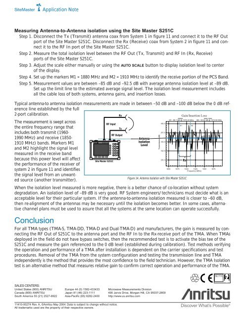
MODE FREQ/DIST AMPLITUDE SWEEP1STARTCAL3SAVESETUPLIMIT7SAVEDISPLAY9ONOFF2AUTOSCALE4RECALLSETUP5 6MARKER8RECALLDISPLAY0PRINT.ESCAPECLEARENTERRUNHOLD+/-SYSSiteMasterApplication NoteMeasuring Antenna-to-Antenna isolation using the Site Master S251CStep 1. Disconnect the Tx (Transmit) antenna coax from System 1 in figure 11 <strong>and</strong> connect it to the RF Outport of the Site Master S251C. Disconnect the Rx (Receive) coax from System 2 in figure 11 <strong>and</strong> connectit to the RF In port of the Site Master S251C.Step 2. Measure the total isolation level between the RF Out (Tx, Transmit) <strong>and</strong> RF In (Rx, Receive)ports of the Site Master S251C.Step 3. Adjust the scale either manually or using the AUTO SCALE button to display isolation level to centerof the display.Step 4. Set up the markers M1 = 1880 MHz <strong>and</strong> M2 = 1910 MHz to identify the receive portion of the PCS B<strong>and</strong>.Step 5. Measurement values are between –85 dB <strong>and</strong> –92.5 dB with average antenna isolation level at –89 dB.Set up the limit line to the estimated average signal level. The isolation level measurement includesall the cable loss of both systems, antenna gains, <strong>and</strong> insertion losses.Typical antenna-to antenna isolation measurements are made in between –50 dB <strong>and</strong> –100 dB below the 0 dB referenceline established by the full2-port calibration.The measurement is swept acrossthe entire frequency range thatincludes both transmit (1960-1990 MHz) <strong>and</strong> receive (1850-1910 MHz) b<strong>and</strong>s. Markers M1<strong>and</strong> M2 highlight the signal levelmeasured in the receive b<strong>and</strong>because this power level will affectthe performance of the receiver ofsystem 2 in figure 11 <strong>and</strong> identifiesthe signal level from an unwantedsource (another transmitter).Site Master S251CRF InputSite Master S251CRxTxRF OutputAntenna<strong>Isolation</strong>LevelWhen the isolation level measured is more negative, there is a better chance of co-location without systemdegradation. An isolation level of –89 dB is very good. RF System engineers/technicians must decide what is anacceptable level for their particular system. If the antenna-to-antenna isolation measured is closer to –60 dB,then re-alignment of the antennas may be necessary until the isolation becomes better. In some cases, alternativechannel plans must be used to assure that all the systems at the same location can operate successfully.Transmission (dB)-85.0-87.5-90.0-92.5-95.0Gain/Insertion LossM1: -88.11dB @ 1979.30 MHz M2: -92.62 dB @ 1910.80 MHzRxFigure 14. Antenna <strong>Isolation</strong> with Site Master S251C1850 1875 1900 1925 1950 1975Frequency (MHz)ConclusionFor all TMA types (TMA-S, TMA-DD, TMA-D <strong>and</strong> Dual-TMA-D) <strong>and</strong> manufacturers, the gain is measured by connectingthe RF Out of S251C to the antenna port <strong>and</strong> the RF In to the Rx-receive port of the TMA. When TMAsdeployed in the field do not have bypass switches, then the recommended test is to activate the bias tee of theS251C <strong>and</strong> measure the gain referenced to the 0 dB level (established during calibration). Test methods verifyingthe operation <strong>and</strong> performance of a TMA after installation is dependent on the carrier specifications <strong>and</strong> testprocedures. Removal of the TMA from the system configuration <strong>and</strong> testing the transmission line <strong>and</strong> TMAindependently is the method that provides the most confidence to the field technician. However, the TMA <strong>Isolation</strong>test is an alternative method that measures relative gain to confirm correct operation <strong>and</strong> performance of the TMA.M1M2SALES CENTERS:United States (800) ANRITSU Europe 44 (0) 1582-433433 Microwave Measurements DivisionCanada (800) ANRITSU Japan 81 (46) 223-1111 490 Jarvis Drive, Morgan Hill, CA 95037-2809South America 55 (21) 2527-6922 Asia-Pacific (65) 6282-2400 http://www.us.anritsu.com11410-00274 Rev. A, ©Anritsu May 2004. Data is subject to change without notice.All trademarks used are the property of their respective owners.Discover What’s Possible ®